EP3608519B1 - Procédé et dispositif de traitement d'échappement d'un moteur à combustion - Google Patents
Procédé et dispositif de traitement d'échappement d'un moteur à combustion Download PDFInfo
- Publication number
- EP3608519B1 EP3608519B1 EP19190290.7A EP19190290A EP3608519B1 EP 3608519 B1 EP3608519 B1 EP 3608519B1 EP 19190290 A EP19190290 A EP 19190290A EP 3608519 B1 EP3608519 B1 EP 3608519B1
- Authority
- EP
- European Patent Office
- Prior art keywords
- catalytic converter
- exhaust gas
- catalyst
- lambda
- temperature
- Prior art date
- Legal status (The legal status is an assumption and is not a legal conclusion. Google has not performed a legal analysis and makes no representation as to the accuracy of the status listed.)
- Active
Links
Images

Classifications
-
- F—MECHANICAL ENGINEERING; LIGHTING; HEATING; WEAPONS; BLASTING
- F01—MACHINES OR ENGINES IN GENERAL; ENGINE PLANTS IN GENERAL; STEAM ENGINES
- F01N—GAS-FLOW SILENCERS OR EXHAUST APPARATUS FOR MACHINES OR ENGINES IN GENERAL; GAS-FLOW SILENCERS OR EXHAUST APPARATUS FOR INTERNAL-COMBUSTION ENGINES
- F01N3/00—Exhaust or silencing apparatus having means for purifying, rendering innocuous, or otherwise treating exhaust
- F01N3/08—Exhaust or silencing apparatus having means for purifying, rendering innocuous, or otherwise treating exhaust for rendering innocuous
- F01N3/0807—Exhaust or silencing apparatus having means for purifying, rendering innocuous, or otherwise treating exhaust for rendering innocuous by using absorbents or adsorbents
- F01N3/0821—Exhaust or silencing apparatus having means for purifying, rendering innocuous, or otherwise treating exhaust for rendering innocuous by using absorbents or adsorbents combined with particulate filter
-
- F—MECHANICAL ENGINEERING; LIGHTING; HEATING; WEAPONS; BLASTING
- F01—MACHINES OR ENGINES IN GENERAL; ENGINE PLANTS IN GENERAL; STEAM ENGINES
- F01N—GAS-FLOW SILENCERS OR EXHAUST APPARATUS FOR MACHINES OR ENGINES IN GENERAL; GAS-FLOW SILENCERS OR EXHAUST APPARATUS FOR INTERNAL-COMBUSTION ENGINES
- F01N9/00—Electrical control of exhaust gas treating apparatus
-
- F—MECHANICAL ENGINEERING; LIGHTING; HEATING; WEAPONS; BLASTING
- F01—MACHINES OR ENGINES IN GENERAL; ENGINE PLANTS IN GENERAL; STEAM ENGINES
- F01N—GAS-FLOW SILENCERS OR EXHAUST APPARATUS FOR MACHINES OR ENGINES IN GENERAL; GAS-FLOW SILENCERS OR EXHAUST APPARATUS FOR INTERNAL-COMBUSTION ENGINES
- F01N11/00—Monitoring or diagnostic devices for exhaust-gas treatment apparatus
- F01N11/002—Monitoring or diagnostic devices for exhaust-gas treatment apparatus the diagnostic devices measuring or estimating temperature or pressure in, or downstream of the exhaust apparatus
-
- F—MECHANICAL ENGINEERING; LIGHTING; HEATING; WEAPONS; BLASTING
- F01—MACHINES OR ENGINES IN GENERAL; ENGINE PLANTS IN GENERAL; STEAM ENGINES
- F01N—GAS-FLOW SILENCERS OR EXHAUST APPARATUS FOR MACHINES OR ENGINES IN GENERAL; GAS-FLOW SILENCERS OR EXHAUST APPARATUS FOR INTERNAL-COMBUSTION ENGINES
- F01N11/00—Monitoring or diagnostic devices for exhaust-gas treatment apparatus
- F01N11/007—Monitoring or diagnostic devices for exhaust-gas treatment apparatus the diagnostic devices measuring oxygen or air concentration downstream of the exhaust apparatus
-
- F—MECHANICAL ENGINEERING; LIGHTING; HEATING; WEAPONS; BLASTING
- F01—MACHINES OR ENGINES IN GENERAL; ENGINE PLANTS IN GENERAL; STEAM ENGINES
- F01N—GAS-FLOW SILENCERS OR EXHAUST APPARATUS FOR MACHINES OR ENGINES IN GENERAL; GAS-FLOW SILENCERS OR EXHAUST APPARATUS FOR INTERNAL-COMBUSTION ENGINES
- F01N13/00—Exhaust or silencing apparatus characterised by constructional features
- F01N13/009—Exhaust or silencing apparatus characterised by constructional features having two or more separate purifying devices arranged in series
-
- F—MECHANICAL ENGINEERING; LIGHTING; HEATING; WEAPONS; BLASTING
- F01—MACHINES OR ENGINES IN GENERAL; ENGINE PLANTS IN GENERAL; STEAM ENGINES
- F01N—GAS-FLOW SILENCERS OR EXHAUST APPARATUS FOR MACHINES OR ENGINES IN GENERAL; GAS-FLOW SILENCERS OR EXHAUST APPARATUS FOR INTERNAL-COMBUSTION ENGINES
- F01N13/00—Exhaust or silencing apparatus characterised by constructional features
- F01N13/009—Exhaust or silencing apparatus characterised by constructional features having two or more separate purifying devices arranged in series
- F01N13/0093—Exhaust or silencing apparatus characterised by constructional features having two or more separate purifying devices arranged in series the purifying devices are of the same type
-
- F—MECHANICAL ENGINEERING; LIGHTING; HEATING; WEAPONS; BLASTING
- F01—MACHINES OR ENGINES IN GENERAL; ENGINE PLANTS IN GENERAL; STEAM ENGINES
- F01N—GAS-FLOW SILENCERS OR EXHAUST APPARATUS FOR MACHINES OR ENGINES IN GENERAL; GAS-FLOW SILENCERS OR EXHAUST APPARATUS FOR INTERNAL-COMBUSTION ENGINES
- F01N3/00—Exhaust or silencing apparatus having means for purifying, rendering innocuous, or otherwise treating exhaust
- F01N3/02—Exhaust or silencing apparatus having means for purifying, rendering innocuous, or otherwise treating exhaust for cooling, or for removing solid constituents of, exhaust
- F01N3/021—Exhaust or silencing apparatus having means for purifying, rendering innocuous, or otherwise treating exhaust for cooling, or for removing solid constituents of, exhaust by means of filters
-
- F—MECHANICAL ENGINEERING; LIGHTING; HEATING; WEAPONS; BLASTING
- F01—MACHINES OR ENGINES IN GENERAL; ENGINE PLANTS IN GENERAL; STEAM ENGINES
- F01N—GAS-FLOW SILENCERS OR EXHAUST APPARATUS FOR MACHINES OR ENGINES IN GENERAL; GAS-FLOW SILENCERS OR EXHAUST APPARATUS FOR INTERNAL-COMBUSTION ENGINES
- F01N3/00—Exhaust or silencing apparatus having means for purifying, rendering innocuous, or otherwise treating exhaust
- F01N3/02—Exhaust or silencing apparatus having means for purifying, rendering innocuous, or otherwise treating exhaust for cooling, or for removing solid constituents of, exhaust
- F01N3/021—Exhaust or silencing apparatus having means for purifying, rendering innocuous, or otherwise treating exhaust for cooling, or for removing solid constituents of, exhaust by means of filters
- F01N3/023—Exhaust or silencing apparatus having means for purifying, rendering innocuous, or otherwise treating exhaust for cooling, or for removing solid constituents of, exhaust by means of filters using means for regenerating the filters, e.g. by burning trapped particles
- F01N3/027—Exhaust or silencing apparatus having means for purifying, rendering innocuous, or otherwise treating exhaust for cooling, or for removing solid constituents of, exhaust by means of filters using means for regenerating the filters, e.g. by burning trapped particles using electric or magnetic heating means
-
- F—MECHANICAL ENGINEERING; LIGHTING; HEATING; WEAPONS; BLASTING
- F01—MACHINES OR ENGINES IN GENERAL; ENGINE PLANTS IN GENERAL; STEAM ENGINES
- F01N—GAS-FLOW SILENCERS OR EXHAUST APPARATUS FOR MACHINES OR ENGINES IN GENERAL; GAS-FLOW SILENCERS OR EXHAUST APPARATUS FOR INTERNAL-COMBUSTION ENGINES
- F01N3/00—Exhaust or silencing apparatus having means for purifying, rendering innocuous, or otherwise treating exhaust
- F01N3/08—Exhaust or silencing apparatus having means for purifying, rendering innocuous, or otherwise treating exhaust for rendering innocuous
- F01N3/10—Exhaust or silencing apparatus having means for purifying, rendering innocuous, or otherwise treating exhaust for rendering innocuous by thermal or catalytic conversion of noxious components of exhaust
- F01N3/101—Three-way catalysts
-
- F—MECHANICAL ENGINEERING; LIGHTING; HEATING; WEAPONS; BLASTING
- F01—MACHINES OR ENGINES IN GENERAL; ENGINE PLANTS IN GENERAL; STEAM ENGINES
- F01N—GAS-FLOW SILENCERS OR EXHAUST APPARATUS FOR MACHINES OR ENGINES IN GENERAL; GAS-FLOW SILENCERS OR EXHAUST APPARATUS FOR INTERNAL-COMBUSTION ENGINES
- F01N3/00—Exhaust or silencing apparatus having means for purifying, rendering innocuous, or otherwise treating exhaust
- F01N3/08—Exhaust or silencing apparatus having means for purifying, rendering innocuous, or otherwise treating exhaust for rendering innocuous
- F01N3/10—Exhaust or silencing apparatus having means for purifying, rendering innocuous, or otherwise treating exhaust for rendering innocuous by thermal or catalytic conversion of noxious components of exhaust
- F01N3/18—Exhaust or silencing apparatus having means for purifying, rendering innocuous, or otherwise treating exhaust for rendering innocuous by thermal or catalytic conversion of noxious components of exhaust characterised by methods of operation; Control
- F01N3/20—Exhaust or silencing apparatus having means for purifying, rendering innocuous, or otherwise treating exhaust for rendering innocuous by thermal or catalytic conversion of noxious components of exhaust characterised by methods of operation; Control specially adapted for catalytic conversion
- F01N3/2006—Periodically heating or cooling catalytic reactors, e.g. at cold starting or overheating
- F01N3/2013—Periodically heating or cooling catalytic reactors, e.g. at cold starting or overheating using electric or magnetic heating means
-
- F—MECHANICAL ENGINEERING; LIGHTING; HEATING; WEAPONS; BLASTING
- F01—MACHINES OR ENGINES IN GENERAL; ENGINE PLANTS IN GENERAL; STEAM ENGINES
- F01N—GAS-FLOW SILENCERS OR EXHAUST APPARATUS FOR MACHINES OR ENGINES IN GENERAL; GAS-FLOW SILENCERS OR EXHAUST APPARATUS FOR INTERNAL-COMBUSTION ENGINES
- F01N3/00—Exhaust or silencing apparatus having means for purifying, rendering innocuous, or otherwise treating exhaust
- F01N3/08—Exhaust or silencing apparatus having means for purifying, rendering innocuous, or otherwise treating exhaust for rendering innocuous
- F01N3/10—Exhaust or silencing apparatus having means for purifying, rendering innocuous, or otherwise treating exhaust for rendering innocuous by thermal or catalytic conversion of noxious components of exhaust
- F01N3/18—Exhaust or silencing apparatus having means for purifying, rendering innocuous, or otherwise treating exhaust for rendering innocuous by thermal or catalytic conversion of noxious components of exhaust characterised by methods of operation; Control
- F01N3/20—Exhaust or silencing apparatus having means for purifying, rendering innocuous, or otherwise treating exhaust for rendering innocuous by thermal or catalytic conversion of noxious components of exhaust characterised by methods of operation; Control specially adapted for catalytic conversion
- F01N3/2006—Periodically heating or cooling catalytic reactors, e.g. at cold starting or overheating
- F01N3/2013—Periodically heating or cooling catalytic reactors, e.g. at cold starting or overheating using electric or magnetic heating means
- F01N3/2026—Periodically heating or cooling catalytic reactors, e.g. at cold starting or overheating using electric or magnetic heating means directly electrifying the catalyst substrate, i.e. heating the electrically conductive catalyst substrate by joule effect
-
- F—MECHANICAL ENGINEERING; LIGHTING; HEATING; WEAPONS; BLASTING
- F01—MACHINES OR ENGINES IN GENERAL; ENGINE PLANTS IN GENERAL; STEAM ENGINES
- F01N—GAS-FLOW SILENCERS OR EXHAUST APPARATUS FOR MACHINES OR ENGINES IN GENERAL; GAS-FLOW SILENCERS OR EXHAUST APPARATUS FOR INTERNAL-COMBUSTION ENGINES
- F01N3/00—Exhaust or silencing apparatus having means for purifying, rendering innocuous, or otherwise treating exhaust
- F01N3/08—Exhaust or silencing apparatus having means for purifying, rendering innocuous, or otherwise treating exhaust for rendering innocuous
- F01N3/10—Exhaust or silencing apparatus having means for purifying, rendering innocuous, or otherwise treating exhaust for rendering innocuous by thermal or catalytic conversion of noxious components of exhaust
- F01N3/18—Exhaust or silencing apparatus having means for purifying, rendering innocuous, or otherwise treating exhaust for rendering innocuous by thermal or catalytic conversion of noxious components of exhaust characterised by methods of operation; Control
- F01N3/20—Exhaust or silencing apparatus having means for purifying, rendering innocuous, or otherwise treating exhaust for rendering innocuous by thermal or catalytic conversion of noxious components of exhaust characterised by methods of operation; Control specially adapted for catalytic conversion
- F01N3/2006—Periodically heating or cooling catalytic reactors, e.g. at cold starting or overheating
- F01N3/2033—Periodically heating or cooling catalytic reactors, e.g. at cold starting or overheating using a fuel burner or introducing fuel into exhaust duct
-
- F—MECHANICAL ENGINEERING; LIGHTING; HEATING; WEAPONS; BLASTING
- F01—MACHINES OR ENGINES IN GENERAL; ENGINE PLANTS IN GENERAL; STEAM ENGINES
- F01N—GAS-FLOW SILENCERS OR EXHAUST APPARATUS FOR MACHINES OR ENGINES IN GENERAL; GAS-FLOW SILENCERS OR EXHAUST APPARATUS FOR INTERNAL-COMBUSTION ENGINES
- F01N3/00—Exhaust or silencing apparatus having means for purifying, rendering innocuous, or otherwise treating exhaust
- F01N3/08—Exhaust or silencing apparatus having means for purifying, rendering innocuous, or otherwise treating exhaust for rendering innocuous
- F01N3/10—Exhaust or silencing apparatus having means for purifying, rendering innocuous, or otherwise treating exhaust for rendering innocuous by thermal or catalytic conversion of noxious components of exhaust
- F01N3/24—Exhaust or silencing apparatus having means for purifying, rendering innocuous, or otherwise treating exhaust for rendering innocuous by thermal or catalytic conversion of noxious components of exhaust characterised by constructional aspects of converting apparatus
- F01N3/38—Arrangements for igniting
-
- F—MECHANICAL ENGINEERING; LIGHTING; HEATING; WEAPONS; BLASTING
- F02—COMBUSTION ENGINES; HOT-GAS OR COMBUSTION-PRODUCT ENGINE PLANTS
- F02D—CONTROLLING COMBUSTION ENGINES
- F02D41/00—Electrical control of supply of combustible mixture or its constituents
- F02D41/02—Circuit arrangements for generating control signals
- F02D41/021—Introducing corrections for particular conditions exterior to the engine
- F02D41/0235—Introducing corrections for particular conditions exterior to the engine in relation with the state of the exhaust gas treating apparatus
- F02D41/024—Introducing corrections for particular conditions exterior to the engine in relation with the state of the exhaust gas treating apparatus to increase temperature of the exhaust gas treating apparatus
- F02D41/025—Introducing corrections for particular conditions exterior to the engine in relation with the state of the exhaust gas treating apparatus to increase temperature of the exhaust gas treating apparatus by changing the composition of the exhaust gas, e.g. for exothermic reaction on exhaust gas treating apparatus
-
- F—MECHANICAL ENGINEERING; LIGHTING; HEATING; WEAPONS; BLASTING
- F02—COMBUSTION ENGINES; HOT-GAS OR COMBUSTION-PRODUCT ENGINE PLANTS
- F02D—CONTROLLING COMBUSTION ENGINES
- F02D41/00—Electrical control of supply of combustible mixture or its constituents
- F02D41/02—Circuit arrangements for generating control signals
- F02D41/021—Introducing corrections for particular conditions exterior to the engine
- F02D41/0235—Introducing corrections for particular conditions exterior to the engine in relation with the state of the exhaust gas treating apparatus
- F02D41/024—Introducing corrections for particular conditions exterior to the engine in relation with the state of the exhaust gas treating apparatus to increase temperature of the exhaust gas treating apparatus
- F02D41/0255—Introducing corrections for particular conditions exterior to the engine in relation with the state of the exhaust gas treating apparatus to increase temperature of the exhaust gas treating apparatus to accelerate the warming-up of the exhaust gas treating apparatus at engine start
-
- F—MECHANICAL ENGINEERING; LIGHTING; HEATING; WEAPONS; BLASTING
- F02—COMBUSTION ENGINES; HOT-GAS OR COMBUSTION-PRODUCT ENGINE PLANTS
- F02D—CONTROLLING COMBUSTION ENGINES
- F02D41/00—Electrical control of supply of combustible mixture or its constituents
- F02D41/02—Circuit arrangements for generating control signals
- F02D41/14—Introducing closed-loop corrections
- F02D41/1438—Introducing closed-loop corrections using means for determining characteristics of the combustion gases; Sensors therefor
- F02D41/1444—Introducing closed-loop corrections using means for determining characteristics of the combustion gases; Sensors therefor characterised by the characteristics of the combustion gases
- F02D41/1454—Introducing closed-loop corrections using means for determining characteristics of the combustion gases; Sensors therefor characterised by the characteristics of the combustion gases the characteristics being an oxygen content or concentration or the air-fuel ratio
-
- F—MECHANICAL ENGINEERING; LIGHTING; HEATING; WEAPONS; BLASTING
- F01—MACHINES OR ENGINES IN GENERAL; ENGINE PLANTS IN GENERAL; STEAM ENGINES
- F01N—GAS-FLOW SILENCERS OR EXHAUST APPARATUS FOR MACHINES OR ENGINES IN GENERAL; GAS-FLOW SILENCERS OR EXHAUST APPARATUS FOR INTERNAL-COMBUSTION ENGINES
- F01N2240/00—Combination or association of two or more different exhaust treating devices, or of at least one such device with an auxiliary device, not covered by indexing codes F01N2230/00 or F01N2250/00, one of the devices being
- F01N2240/16—Combination or association of two or more different exhaust treating devices, or of at least one such device with an auxiliary device, not covered by indexing codes F01N2230/00 or F01N2250/00, one of the devices being an electric heater, i.e. a resistance heater
-
- F—MECHANICAL ENGINEERING; LIGHTING; HEATING; WEAPONS; BLASTING
- F01—MACHINES OR ENGINES IN GENERAL; ENGINE PLANTS IN GENERAL; STEAM ENGINES
- F01N—GAS-FLOW SILENCERS OR EXHAUST APPARATUS FOR MACHINES OR ENGINES IN GENERAL; GAS-FLOW SILENCERS OR EXHAUST APPARATUS FOR INTERNAL-COMBUSTION ENGINES
- F01N2560/00—Exhaust systems with means for detecting or measuring exhaust gas components or characteristics
- F01N2560/02—Exhaust systems with means for detecting or measuring exhaust gas components or characteristics the means being an exhaust gas sensor
- F01N2560/025—Exhaust systems with means for detecting or measuring exhaust gas components or characteristics the means being an exhaust gas sensor for measuring or detecting O2, e.g. lambda sensors
-
- F—MECHANICAL ENGINEERING; LIGHTING; HEATING; WEAPONS; BLASTING
- F01—MACHINES OR ENGINES IN GENERAL; ENGINE PLANTS IN GENERAL; STEAM ENGINES
- F01N—GAS-FLOW SILENCERS OR EXHAUST APPARATUS FOR MACHINES OR ENGINES IN GENERAL; GAS-FLOW SILENCERS OR EXHAUST APPARATUS FOR INTERNAL-COMBUSTION ENGINES
- F01N2560/00—Exhaust systems with means for detecting or measuring exhaust gas components or characteristics
- F01N2560/14—Exhaust systems with means for detecting or measuring exhaust gas components or characteristics having more than one sensor of one kind
-
- F—MECHANICAL ENGINEERING; LIGHTING; HEATING; WEAPONS; BLASTING
- F01—MACHINES OR ENGINES IN GENERAL; ENGINE PLANTS IN GENERAL; STEAM ENGINES
- F01N—GAS-FLOW SILENCERS OR EXHAUST APPARATUS FOR MACHINES OR ENGINES IN GENERAL; GAS-FLOW SILENCERS OR EXHAUST APPARATUS FOR INTERNAL-COMBUSTION ENGINES
- F01N2900/00—Details of electrical control or of the monitoring of the exhaust gas treating apparatus
- F01N2900/04—Methods of control or diagnosing
- F01N2900/0416—Methods of control or diagnosing using the state of a sensor, e.g. of an exhaust gas sensor
-
- F—MECHANICAL ENGINEERING; LIGHTING; HEATING; WEAPONS; BLASTING
- F01—MACHINES OR ENGINES IN GENERAL; ENGINE PLANTS IN GENERAL; STEAM ENGINES
- F01N—GAS-FLOW SILENCERS OR EXHAUST APPARATUS FOR MACHINES OR ENGINES IN GENERAL; GAS-FLOW SILENCERS OR EXHAUST APPARATUS FOR INTERNAL-COMBUSTION ENGINES
- F01N2900/00—Details of electrical control or of the monitoring of the exhaust gas treating apparatus
- F01N2900/06—Parameters used for exhaust control or diagnosing
- F01N2900/08—Parameters used for exhaust control or diagnosing said parameters being related to the engine
-
- F—MECHANICAL ENGINEERING; LIGHTING; HEATING; WEAPONS; BLASTING
- F01—MACHINES OR ENGINES IN GENERAL; ENGINE PLANTS IN GENERAL; STEAM ENGINES
- F01N—GAS-FLOW SILENCERS OR EXHAUST APPARATUS FOR MACHINES OR ENGINES IN GENERAL; GAS-FLOW SILENCERS OR EXHAUST APPARATUS FOR INTERNAL-COMBUSTION ENGINES
- F01N2900/00—Details of electrical control or of the monitoring of the exhaust gas treating apparatus
- F01N2900/06—Parameters used for exhaust control or diagnosing
- F01N2900/14—Parameters used for exhaust control or diagnosing said parameters being related to the exhaust gas
- F01N2900/1402—Exhaust gas composition
-
- F—MECHANICAL ENGINEERING; LIGHTING; HEATING; WEAPONS; BLASTING
- F01—MACHINES OR ENGINES IN GENERAL; ENGINE PLANTS IN GENERAL; STEAM ENGINES
- F01N—GAS-FLOW SILENCERS OR EXHAUST APPARATUS FOR MACHINES OR ENGINES IN GENERAL; GAS-FLOW SILENCERS OR EXHAUST APPARATUS FOR INTERNAL-COMBUSTION ENGINES
- F01N2900/00—Details of electrical control or of the monitoring of the exhaust gas treating apparatus
- F01N2900/06—Parameters used for exhaust control or diagnosing
- F01N2900/14—Parameters used for exhaust control or diagnosing said parameters being related to the exhaust gas
- F01N2900/1404—Exhaust gas temperature
-
- F—MECHANICAL ENGINEERING; LIGHTING; HEATING; WEAPONS; BLASTING
- F01—MACHINES OR ENGINES IN GENERAL; ENGINE PLANTS IN GENERAL; STEAM ENGINES
- F01N—GAS-FLOW SILENCERS OR EXHAUST APPARATUS FOR MACHINES OR ENGINES IN GENERAL; GAS-FLOW SILENCERS OR EXHAUST APPARATUS FOR INTERNAL-COMBUSTION ENGINES
- F01N2900/00—Details of electrical control or of the monitoring of the exhaust gas treating apparatus
- F01N2900/06—Parameters used for exhaust control or diagnosing
- F01N2900/16—Parameters used for exhaust control or diagnosing said parameters being related to the exhaust apparatus, e.g. particulate filter or catalyst
- F01N2900/1602—Temperature of exhaust gas apparatus
-
- Y—GENERAL TAGGING OF NEW TECHNOLOGICAL DEVELOPMENTS; GENERAL TAGGING OF CROSS-SECTIONAL TECHNOLOGIES SPANNING OVER SEVERAL SECTIONS OF THE IPC; TECHNICAL SUBJECTS COVERED BY FORMER USPC CROSS-REFERENCE ART COLLECTIONS [XRACs] AND DIGESTS
- Y02—TECHNOLOGIES OR APPLICATIONS FOR MITIGATION OR ADAPTATION AGAINST CLIMATE CHANGE
- Y02T—CLIMATE CHANGE MITIGATION TECHNOLOGIES RELATED TO TRANSPORTATION
- Y02T10/00—Road transport of goods or passengers
- Y02T10/10—Internal combustion engine [ICE] based vehicles
- Y02T10/12—Improving ICE efficiencies
Definitions
- the invention relates to a method for exhaust gas aftertreatment of an internal combustion engine and to an exhaust gas aftertreatment system for carrying out such a method according to the preambles of the independent patent claims.
- a method for operating an internal combustion engine for a motor vehicle with an exhaust system is known in which at least one catalyst and at least one lambda probe are arranged. After a cold start, the internal combustion engine is operated alternately with a lean and rich fuel-air mixture to heat up the catalyst. The lambda probe is heated after the cold start so that it is ready for operation after a maximum of ten seconds and the internal combustion engine is operated with a two-point control based on a signal from the lambda probe. Switching between operation with a lean fuel-air mixture and with a rich fuel-air mixture is triggered by the signal from the lambda sensor.
- the second lambda probe is designed as a jump probe.
- a diagnosis of a characteristic curve offset of the first lambda probe and, if necessary, an adaptation of a characteristic curve offset error are carried out.
- For the diagnosis, with active lambda adjustment a value that represents the oxygen storage capacity of the catalytic converter and another value that represents the oxygen removal capacity from the catalytic converter are recorded.
- a characteristic curve offset of the first lambda probe is calculated from the ratio of oxygen storage capacity and oxygen removal capacity.
- the EP 2 884 066 A1 discloses a method for diagnosing an object such as a catalyst or a filter.
- a front side of the catalyst is exposed to a test medium with a defined composition such as propane gas or carbon monoxide by means of a device through an opening and a concentration of at least one reduced or oxidized component of the test medium is measured at a downstream position after passing through the catalyst.
- a defined composition such as propane gas or carbon monoxide
- a combustion engine with an exhaust aftertreatment system in which an exhaust gas burner is arranged, with which the heating of a three-way catalyst in the exhaust aftertreatment system can be accelerated. It is provided that the exhaust gas burner is operated in a cold start phase of the combustion engine and remains activated at least until the three-way catalyst has reached its light-off temperature.
- the DE 10 2012 011 113 A1 discloses an exhaust system for an internal combustion engine with at least two exhaust aftertreatment components connected in series in terms of flow, wherein the rear of the two exhaust aftertreatment components can be heated by means of an electric heating element.
- the DE 10 2017 100 892 A1 discloses a method for regenerating a particle filter in the exhaust system of an internal combustion engine. It is provided that during lean operation of the internal combustion engine, the nitrogen oxides that can no longer be converted by a three-way catalyst are stored in a nitrogen oxide storage catalyst in order to provide the oxygen for regenerating the particle filter.
- a method for controlling an internal combustion engine in a hybrid drive is known. It is first determined whether cold start conditions exist for the internal combustion engine and, in the case of cold start conditions, an electrically heated catalyst is activated. As soon as the electrically heated catalyst has reached a threshold temperature, the internal combustion engine is switched on.
- the invention is based on the object of further improving the conversion performance of the exhaust gas aftertreatment system and in particular of adapting the lambda control in such a way that the efficiency of the exhaust gas aftertreatment components can be further increased.
- the method according to the invention makes it possible to provide an additional catalyst volume for converting the pollutant components shortly after passive heating due to the load condition imposed by the driver. This is particularly important for higher-load driving profiles, as in this case the catalytically active surface is used optimally.
- the active catalyst volume is used as efficiently as possible. This enables particularly efficient conversion of the pollutants, which can minimize tailpipe emissions.
- lambda control is carried out by the first lambda probe from the start of the internal combustion engine.
- Lambda control to a stoichiometric combustion air ratio in the cold start phase can minimize the raw emissions of the internal combustion engine, particularly when none of the catalysts has yet reached its light-off temperature and exhaust gas aftertreatment by the catalysts is not yet possible.
- lambda control is extended to the lambda probe downstream of the actively heatable catalyst as soon as this catalyst has reached its light-off temperature. By extending lambda control to the lambda probe downstream of the actively heatable catalyst, the available catalytically effective exhaust gas aftertreatment volume is increased.
- active heating is stopped as soon as the catalyst has reached its light-off temperature. This reduces the energy requirement of the exhaust gas aftertreatment system and relieves the load on the vehicle's battery. The catalyst is then further heated by the exothermic reaction of the exhaust gas components on the surface of the catalyst.
- the lambda control is carried out by the first lambda probe and the second lambda probe upstream and downstream of the first catalyst when the temperature of the actively heatable catalyst falls below its light-off temperature during operation of the combustion engine.
- active heating is reactivated when the temperature of the actively heated catalyst has fallen below its light-off temperature during operation of the combustion engine. Active heating allows the actively heated catalyst to be heated back up to its light-off temperature, so that the available catalytically effective catalyst volume is increased. This can improve the conversion performance of the exhaust gas aftertreatment system and reduce tailpipe emissions.
- an expected load profile of the combustion engine is determined and the actively heated catalyst is heated if, based on the expected load profile, a drop in the component temperature of the actively heated catalyst is assumed to be below its light-off temperature.
- the driving behavior of the driver can be determined and/or the driver's preferred driving routes can be recognized. This can be done, for example, using the vehicle's navigation data or an evaluation of the engine data. If it is recognized that the next expected driving section will probably be driven through with the combustion engine operating at low load, in which the temperature of the electrically heated catalyst drops below its light-off temperature, the heated catalyst in order to continue to provide the largest possible active catalyst volume.
- an exhaust gas aftertreatment system for an internal combustion engine which can be connected to an outlet of the internal combustion engine, is proposed.
- the exhaust gas aftertreatment system comprises an exhaust system in which a first catalyst, a second catalyst downstream of the first catalyst and a third catalyst downstream of the second catalyst are arranged in the flow direction of an exhaust gas through the exhaust system.
- a first lambda probe is arranged upstream of the first catalyst and a second lambda probe is arranged downstream of the first catalyst and upstream of the second catalyst.
- a third lambda probe is arranged downstream of the second catalyst and upstream of the third catalyst.
- the first catalyst and the third catalyst are designed as three-way catalysts.
- the second catalyst is designed as a three-way catalyst that can be actively heated electrically by means of an electric heating element.
- the exhaust gas aftertreatment system additionally comprises a control unit that is set up to carry out a method according to the invention when a machine-readable program code is executed by the control unit. Such an exhaust gas aftertreatment system makes it possible to improve the conversion performance of the catalysts and reduce emissions.
- a fourth catalyst is arranged downstream of the first catalyst and upstream of the second catalyst.
- An additional catalyst can increase the available catalytically effective catalyst volume. This has advantages not only in the cold start phase, in which the catalytic activity of the catalysts is still limited, but also when the internal combustion engine is operating at full load. In addition, catalysts are subject to an aging process, as a result of which the conversion performance decreases over the lifetime of the catalyst. An additional catalyst creates a reserve here, which ensures that even if the catalysts are significantly aged, there is still sufficient catalyst volume to enable complete conversion of the limited exhaust gas components in all operating situations of the internal combustion engine.
- the fourth catalyst is designed to be essentially free of an oxygen-storage component.
- the fourth catalyst and the second catalyst can be controlled together via a lambda probe.
- the control is not slowed down by filling and emptying an additional oxygen storage device, which means that the efficiency of the exhaust gas aftertreatment can be further increased.
- the actively heatable catalyst comprises an electric heating element.
- An electric heating element in particular an electric heating disk, can be easily and inexpensively integrated into the actively heatable catalyst.
- a heating element can be installed directly upstream of the actively heatable catalyst.
- An electric heating element has the advantage over heating using an exhaust gas burner that it requires comparatively little installation space and can therefore be easily integrated into the exhaust system at little additional cost.
- the first lambda probe is designed as a broadband probe and the other lambda probes are each designed as step probes.
- a broadband probe can be used to quantitatively determine the combustion air ratio in the exhaust duct.
- the step probes can detect a breakthrough through the respective catalyst in order to adjust the combustion air ratio accordingly as part of the lambda control.
- a temperature sensor is arranged in the exhaust system.
- a temperature sensor in the exhaust system can determine the exhaust gas temperature and/or the component temperature of a catalyst. This makes it easier to recognize whether the respective catalyst has reached its light-off temperature.
- the temperature sensor can also be used to provide information in a calculation model for determining the component temperatures and to improve the calculation model.
- FIG. 1 shows an internal combustion engine 10 with an exhaust gas aftertreatment system in a schematic representation.
- the internal combustion engine 10 has a plurality of combustion chambers 12, in each of which a spark plug 14 is arranged.
- the internal combustion engine 10 has an inlet 16, with which the internal combustion engine 10 can be connected to an air supply system (not shown for reasons of clarity).
- the internal combustion engine 10 also has an outlet 18, with which the internal combustion engine 10 is connected to an exhaust system 20, such that an exhaust gas from the combustion chambers 12 of the internal combustion engine 10 can be guided into the exhaust system 20.
- the exhaust system 20 comprises an exhaust duct 22 in which a turbine 26 of an exhaust gas turbocharger 24, downstream of the turbine 26 a first catalyst 28, downstream of the first catalyst 28 a second catalyst 30 and further downstream a third catalyst 32 are arranged in the flow direction of an exhaust gas from the internal combustion engine 10 through the exhaust duct 22.
- the first catalyst 28 is preferably designed as a three-way catalyst and is arranged in a position close to the engine in the exhaust system 20.
- a position close to the engine is understood to mean a position with an exhaust gas path length of less than 80 cm, preferably less than 50 cm, from the outlet 18 of the internal combustion engine 10.
- the second catalyst 30 is designed as a three-way catalyst 36 that can be actively heated by means of an electrical heating element 52.
- the third catalyst 32 is preferably arranged in an underbody position of a motor vehicle and is also designed as a three-way catalyst.
- a first lambda probe 38 is arranged in the exhaust gas duct 22 downstream of the turbine 26 of the exhaust gas turbocharger 34 and upstream of the first catalyst 28.
- the first lambda probe 38 is preferably designed as a broadband probe 44 and thus enables a quantitative assessment of the combustion air ratio upstream of the first catalyst 28.
- Downstream of the first catalyst 28 and upstream of the second A second lambda probe 40, which is preferably designed as a jump probe 46, is provided in the exhaust duct 22 for the catalyst 30.
- a third lambda probe 42 which is preferably designed as a jump probe 46, is arranged in the exhaust duct 22 downstream of the second catalyst 30 and upstream of the third catalyst 32.
- a temperature sensor 48 can also be arranged in the exhaust duct 22 in order to measure the exhaust gas temperature and thus calculate the component temperature of the catalysts 28, 30, 32.
- the filter substrate 56 of the particle filter 54 can also be designed to be electrically conductive and thus directly heatable.
- the internal combustion engine 10 as well as the lambda probes 38, 40, 42 and the temperature sensor 48 are connected to an engine control unit 50 via signal lines. Based on the information from the lambda probes 38, 40, 42 and the temperature sensor 48, the injection quantity, the injection timing and the ignition timing in the combustion chambers 12 are controlled in order to ensure that the fuel-air mixture is burned with as few emissions as possible.
- the second catalytic converter 40 is heated externally by means of an electric heating element 52 after the engine of the internal combustion engine 10 has started or in low-load operating situations of the internal combustion engine 10.
- the heating measures can be reduced or switched off to reduce the overall energy requirement and to protect a battery of the motor vehicle when the first catalytic converter 28 close to the engine has reached its light-off temperature and the second lambda probe 40 downstream of the first catalytic converter 28 can be used for lambda control.
- the lambda control should be extended again to the third lambda probe 42.
- the realization of the variability in the control system of the lambda control requires intelligent detection of the already active catalyst volume. This can be done, for example, by a calculation model stored in the engine control unit 50 of the combustion engine 10.
- FIG 2 An alternative embodiment of an exhaust gas aftertreatment system according to the invention is shown.
- a fourth catalyst 34 is arranged downstream of the first catalyst 28 and upstream of the second catalyst 30.
- the fourth catalyst 34 is preferably designed as a three-way catalyst with a washcoat which is essentially free of an oxygen-storing component. This makes it possible to increase the catalyst volume without requiring an additional lambda probe downstream of this fourth catalyst.
- the washcoat without oxygen storage capacity makes it possible to control the fourth catalyst 34 and the heatable second catalyst 30, 36 together via the third lambda probe 42.
- a further lambda probe can also be provided, the control path of the lambda control being extended to the last lambda probe 38, 40, 42 in the flow direction, the catalyst 28, 30, 32 immediately upstream of which has reached its light-off temperature. If none of the catalysts 28, 30, 32 has reached its light-off temperature, the lambda control is carried out via the first lambda probe 38.
- the Figure 2 The proposed exhaust aftertreatment system also has the advantage of increased ageing resistance.
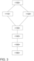
- FIG 3 is a flow chart for carrying out a method according to the invention for exhaust gas aftertreatment of an internal combustion engine 10 with the Figure 1 shown exhaust gas aftertreatment system.
- the lambda control is initially carried out in a first process step ⁇ 110> via the first lambda probe 38, also referred to as the guide probe.
- the electrically heatable catalyst 36 is heated up with the aim of using this catalyst 36 as quickly as possible.
- the third lambda probe 42 downstream of the electrically heatable catalyst 36 is used for the trim control. If the electrically heatable catalyst 36 has reaches its light-off temperature, the heating of this catalyst 36 is deactivated in a next method step ⁇ 130>. This can lead to the electrically heatable catalyst 36 cooling below its light-off temperature, particularly in a low-load phase of the internal combustion engine 10. In this case, the lambda control is switched to the second lambda probe 40 downstream of the first catalyst 28 close to the engine in a next method step ⁇ 140>.
- the lambda control is adjusted back to the third lambda probe 42 in a method step ⁇ 160>.
- the third catalyst 32 in the exhaust system 20 serves to prevent emissions breakthroughs during the on-board diagnosis of the third lambda probe. This third catalyst 32 is not actively integrated into the lambda control.
- the electrically heated catalyst 36 can be heated up to its light-off temperature again by reactivating the electrical heating element 52. This ensures that the catalytic activity of this catalyst 36 is maintained even in low-load phases.
- the lambda control can be extended to the third lambda probe 42 again. This method can be used to maximize the active catalyst volume within the control system of the lambda control.
Landscapes
- Engineering & Computer Science (AREA)
- Chemical & Material Sciences (AREA)
- Combustion & Propulsion (AREA)
- Mechanical Engineering (AREA)
- General Engineering & Computer Science (AREA)
- Chemical Kinetics & Catalysis (AREA)
- Health & Medical Sciences (AREA)
- Toxicology (AREA)
- Materials Engineering (AREA)
- Exhaust Gas After Treatment (AREA)
Claims (11)
- Procédé pour le post-traitement des gaz d'échappement d'un moteur à combustion interne (10) dont l'échappement (18) est relié à un système d'échappement (20), dans lequel un premier catalyseur (28), un deuxième catalyseur (30) en aval du premier catalyseur (28) et un troisième catalyseur (32) en aval du deuxième catalyseur (30) sont disposés dans le système d'échappement (20) dans le sens d'écoulement d'un gaz d'échappement à travers le système d'échappement (20), dans lequel une première sonde lambda (38) est disposée dans un canal d'échappement (22) du système d'échappement (20) en amont du premier catalyseur (28) et une deuxième sonde lambda (40) est disposée en aval du premier catalyseur (28) et en amont du deuxième catalyseur (30), dans lequel une troisième sonde lambda (42) est disposée en aval du deuxième catalyseur (30) et en amont du troisième catalyseur (32), dans lequel le premier catalyseur (28) et le troisième catalyseur (32) sont réalisés sous forme de catalyseurs à trois voies, et dans lequel le deuxième catalyseur (30) est réalisé sous forme de catalyseur à trois voies (36) pouvant être chauffé électriquement de manière active à l'aide d'un élément de chauffage électrique (52), comprenant les étapes suivantes :- chauffage actif du deuxième catalyseur (30) en aval du premier catalyseur (28),- comparaison de la température de composant du premier catalyseur (28), du deuxième catalyseur (30) et du troisième catalyseur (32) avec la température d'amorçage respective du catalyseur (28, 30, 32),- régulation du rapport d'air de combustion par l'intermédiaire d'une régulation lambda du moteur à combustion interne (10) à l'aide de la sonde lambda (38, 40, 42) en aval du dernier catalyseur à trois voies (28, 30, 32) qui a atteint sa température d'amorçage, dans lequel- la régulation lambda s'effectue par l'intermédiaire de la première sonde lambda (38) lorsqu'aucun des catalyseurs (28, 30, 32) n'a atteint sa température d'amorçage, et dans lequel- la régulation lambda est étendue à la sonde lambda (40) en aval du deuxième catalyseur (30) dès que ce catalyseur (30) a atteint sa température d'amorçage.
- Procédé pour le post-traitement des gaz d'échappement selon la revendication 1, caractérisé en ce qu'une régulation lambda est effectuée par la première sonde lambda (38) à partir d'un démarrage de moteur du moteur à combustion interne (10).
- Procédé pour le post-traitement des gaz d'échappement selon l'une des revendications 1 ou 2, caractérisé en ce que le chauffage actif est arrêté dès que le deuxième catalyseur (30) a atteint sa température d'amorçage.
- Procédé pour le post-traitement des gaz d'échappement selon l'une des revendications 1 à 3, caractérisé en ce que la régulation lambda est effectuée par la première sonde lambda (38) et la deuxième sonde lambda (40) en amont et en aval du premier catalyseur (28) lorsque, pendant le fonctionnement du moteur à combustion interne (10), la température du catalyseur (36) pouvant être chauffé activement baisse au-dessous de sa température d'amorçage.
- Procédé pour le post-traitement des gaz d'échappement selon la revendication 4, caractérisé en ce que le chauffage actif est réactivé lorsque la température du catalyseur (36) pouvant être chauffé activement est tombée au-dessous de sa température d'amorçage pendant le fonctionnement du moteur à combustion interne (10).
- Procédé pour le post-traitement des gaz d'échappement selon l'une des revendications 1 à 5, caractérisé en ce qu'un profil de charge attendu du moteur à combustion interne (10) est déterminé et le catalyseur (36) pouvant être chauffé activement est chauffé si, à l'aide du profil de charge attendu, on peut supposer une baisse de la température de composant du catalyseur (36) pouvant être chauffé activement au-dessous de sa température d'amorçage.
- Système pour le post-traitement des gaz d'échappement pour un moteur à combustion interne (10), qui peut être relié à un échappement (18) du moteur à combustion interne (10), dans lequel le système pour le post-traitement des gaz d'échappement comprend un système d'échappement (20) dans lequel, dans le sens d'écoulement d'un gaz d'échappement à travers le système d'échappement (20), un premier catalyseur (28), un deuxième catalyseur (30) en aval du premier catalyseur (28) et un troisième catalyseur (32) en aval du deuxième catalyseur (30) sont disposés, dans lequel une première sonde lambda (38) est disposée dans un canal d'échappement (22) du système d'échappement (20) en amont du premier catalyseur (30) et une deuxième sonde lambda (40) est disposée en aval du premier catalyseur (30) et en amont du deuxième catalyseur (30), et dans lequel une troisième sonde lambda (42) est disposée en aval du deuxième catalyseur (30) et en amont du troisième catalyseur (32), dans lequel le premier catalyseur (28) et le troisième catalyseur (32) sont réalisés sous forme de catalyseurs à trois voies, et dans lequel le deuxième catalyseur (30) est réalisé sous forme de catalyseur à trois voies (36) pouvant être chauffé électriquement de manière active à l'aide d'un élément de chauffage électrique (52), caractérisé en ce que le système pour le post-traitement des gaz d'échappement comprend un appareil de commande (50) qui est conçu pour exécuter un procédé selon l'une des revendications 1 à 6 lorsqu'un code de programme lisible par machine est exécuté par l'appareil de commande (50).
- Système pour le post-traitement des gaz d'échappement selon la revendication 7, caractérisé en ce qu'un quatrième catalyseur (34) est disposé en aval du premier catalyseur (28) et en amont du deuxième catalyseur (30).
- Système pour le post-traitement des gaz d'échappement selon la revendication 8, caractérisé en ce que le quatrième catalyseur (34) est réalisé sensiblement sans composant capable de stocker de l'oxygène.
- Système pour le post-traitement des gaz d'échappement selon l'une des revendications 7 à 9, caractérisé en ce que la première sonde lambda (38) est réalisée sous forme de sonde à large bande (44) et les autres sondes lambda (40, 42) sont réalisées respectivement sous forme de sonde à saut (46).
- Système pour le post-traitement des gaz d'échappement selon l'une des revendications 7 à 10, caractérisé en ce que, dans le système d'échappement (20), est disposé un capteur de température (48).
Applications Claiming Priority (1)
| Application Number | Priority Date | Filing Date | Title |
|---|---|---|---|
| DE102018119156.1A DE102018119156A1 (de) | 2018-08-07 | 2018-08-07 | Verfahren und Vorrichtung zur Abgasnachbehandlung eines Verbrennungsmotors |
Publications (2)
| Publication Number | Publication Date |
|---|---|
| EP3608519A1 EP3608519A1 (fr) | 2020-02-12 |
| EP3608519B1 true EP3608519B1 (fr) | 2024-10-09 |
Family
ID=67551169
Family Applications (1)
| Application Number | Title | Priority Date | Filing Date |
|---|---|---|---|
| EP19190290.7A Active EP3608519B1 (fr) | 2018-08-07 | 2019-08-06 | Procédé et dispositif de traitement d'échappement d'un moteur à combustion |
Country Status (4)
| Country | Link |
|---|---|
| US (1) | US10941689B2 (fr) |
| EP (1) | EP3608519B1 (fr) |
| CN (1) | CN110821619B (fr) |
| DE (1) | DE102018119156A1 (fr) |
Families Citing this family (5)
| Publication number | Priority date | Publication date | Assignee | Title |
|---|---|---|---|---|
| DE102020126717A1 (de) * | 2020-10-12 | 2022-04-14 | Volkswagen Aktiengesellschaft | Verfahren zur Abgasnachbehandlung eines Verbrennungsmotors sowie Kraftfahrzeug mit einem solchen Abgasnachbehandlungssystem |
| DE102020128753A1 (de) | 2020-11-02 | 2022-05-05 | Volkswagen Aktiengesellschaft | Abgasnachbehandlungssystem für einen Verbrennungsmotor sowie Verfahren zur Abgasnachbehandlung |
| US11821350B2 (en) | 2021-07-09 | 2023-11-21 | Tenneco Automotive Operating Company Inc. | Multi-tier exhaust burner control for SCR catalyst pre-heating |
| DE102022103558A1 (de) * | 2022-02-15 | 2023-08-17 | Audi Aktiengesellschaft | Vorrichtung und Verfahren zur Lambdaregelung von Ottomotoren und Kraftfahrzeug |
| US11713704B1 (en) | 2022-04-28 | 2023-08-01 | Tenneco Automotive Operating Company Inc. | Exhaust burner control for reduced fuel consumption |
Family Cites Families (13)
| Publication number | Priority date | Publication date | Assignee | Title |
|---|---|---|---|---|
| JP4357241B2 (ja) * | 2003-09-08 | 2009-11-04 | トヨタ自動車株式会社 | 排気浄化装置 |
| US7111451B2 (en) * | 2004-09-16 | 2006-09-26 | Delphi Technologies, Inc. | NOx adsorber diagnostics and automotive exhaust control system utilizing the same |
| DE102005054733A1 (de) | 2005-11-17 | 2007-05-24 | Robert Bosch Gmbh | Brenner zur Katalysatoraufheizung mit gesteuerter oder geregelter Kraftstoffzuführung |
| US8209970B2 (en) * | 2007-05-15 | 2012-07-03 | GM Global Technology Operations LLC | Hybrid cold start strategy using electrically heated catalyst |
| DE102010002586A1 (de) * | 2010-03-04 | 2011-09-08 | Robert Bosch Gmbh | Verfahren zum Betreiben eines Verbrennungsmotors |
| US8464523B2 (en) | 2010-03-12 | 2013-06-18 | GM Global Technology Operations LLC | Targeted particulate matter filter regeneration system |
| DE102010014468B4 (de) * | 2010-04-09 | 2013-10-31 | Umicore Ag & Co. Kg | Verfahren zur Verminderung von Lachgas bei der Abgasnachbehandlung von Magermotoren |
| DE102012011113A1 (de) * | 2012-06-05 | 2013-12-05 | Audi Ag | Abgasstrang einer Brennkraftmaschine |
| DE102013201734A1 (de) * | 2013-02-04 | 2014-08-07 | Robert Bosch Gmbh | Verfahren zum Betreiben einer Lambdasondenanordnung im Abgassystem einer Brennkraftmaschine |
| PL2884066T3 (pl) | 2013-12-11 | 2017-07-31 | Hirtenberger Aktiengesellschaft | Sposób diagnozowania obiektu jak również urządzenie do tego sposobu |
| US20160160723A1 (en) * | 2014-12-05 | 2016-06-09 | Ford Global Technologies, Llc | Method and system for removing ash within a particulate filter |
| DE102017100892A1 (de) | 2017-01-18 | 2018-07-19 | Volkswagen Aktiengesellschaft | Regeneration eines Partikelfilters oder Vier-Wege-Katalysators in einer Abgasanlage eines Verbrennungsmotors |
| DE102017118215A1 (de) * | 2017-08-10 | 2019-02-14 | Volkswagen Ag | Abgasnachbehandlungssystem und Verfahren zur Abgasnachbehandlung eines Verbrennungsmotors |
-
2018
- 2018-08-07 DE DE102018119156.1A patent/DE102018119156A1/de not_active Withdrawn
-
2019
- 2019-08-06 EP EP19190290.7A patent/EP3608519B1/fr active Active
- 2019-08-07 CN CN201910725139.5A patent/CN110821619B/zh active Active
- 2019-08-07 US US16/534,091 patent/US10941689B2/en active Active
Also Published As
| Publication number | Publication date |
|---|---|
| CN110821619A (zh) | 2020-02-21 |
| EP3608519A1 (fr) | 2020-02-12 |
| US20200049050A1 (en) | 2020-02-13 |
| CN110821619B (zh) | 2021-10-12 |
| US10941689B2 (en) | 2021-03-09 |
| DE102018119156A1 (de) | 2020-02-13 |
Similar Documents
| Publication | Publication Date | Title |
|---|---|---|
| EP3608519B1 (fr) | Procédé et dispositif de traitement d'échappement d'un moteur à combustion | |
| EP3572634B1 (fr) | Procédé et dispositif de traitement des gaz d'échappement d'un moteur à combustion interne | |
| EP3642460B1 (fr) | Système de retraitement des gaz d'échappement et procédé pour le retraitement des gaz d'échappement d'un moteur a combustion interne | |
| EP3686404B1 (fr) | Dispositif et procédé de post-traitement des gaz d'échappement d'un moteur à combustion interne | |
| EP4095364B1 (fr) | Procédé permettant de faire fonctionner un moteur à combustion interne | |
| EP3584418B1 (fr) | Système de post-traitement des gaz d'échappement et procédé de régénération d'un filtre à particules | |
| EP3581771B1 (fr) | Système de traitement de gaz d'échappement et procédé de régénération d'un filtre à particules | |
| WO2019030315A1 (fr) | Système et procédé de retraitement de gaz d'échappement d'un moteur à combustion interne | |
| EP1579109A1 (fr) | Dispositif et procede de post-traitement de gaz d'echappement | |
| EP3652420B1 (fr) | Système et méthode pour post-traitement des gaz d'échappement d'un moteur à combustion interne | |
| WO2020161215A1 (fr) | Système de post-traitement de gaz d'échappement et procédé pour le post-traitement de gaz d'échappement d'un moteur à combustion interne | |
| DE102017205664A1 (de) | Abgasnachbehandlungsvorrichtung und Verfahren zur Abgasnachbehandlung eines Verbrennungsmotors | |
| EP3610148B1 (fr) | Procédé pour faire fonctionner un moteur à combustion interne et véhicule automobile équipé d'un moteur à combustion interne | |
| EP4080027A1 (fr) | Procédé de mise en uvre d'un diagnostic embarqué d'un catalyseur de gaz d'échappement | |
| EP1224385B1 (fr) | PROCEDE POUR ETABLIR UN DIAGNOSTIC SUR UN ETAT DE DETERIORATION DANS UN POT CATALYTIQUE A ACCUMULATION DE NOx MONTE DANS UN CANAL DE GAZ D'ECHAPPEMENT D'UN MOTEUR A COMBUSTION INTERNE | |
| DE102015215365A1 (de) | Verfahren zur Regeneration von Abgasnachbehandlungskomponenten eines Verbrennungsmotors sowie Abgasnachbehandlungsvorrichtung für einen Verbrennungsmotor | |
| DE102015213617A1 (de) | Vorrichtung und Verfahren zur Abgasnachbehandlung eines Verbrennungsmotors | |
| DE102022208296A1 (de) | Verfahren zur Leistungseinstellung einer Verbrennungskraftmaschine | |
| EP3833858B1 (fr) | Procédé et dispositif de post-traitement de gaz d'échappement d'un moteur à combustion interne | |
| DE10338181B4 (de) | Verfahren und Vorrichtung zur Temperaturbeeinflussung eines Katalysatorsystems | |
| DE102016210897A1 (de) | Steuerung einer Stickoxidemission in Betriebsphasen hoher Last | |
| DE10047809B4 (de) | Vefahren zur Betriebssteuerung einer Sekundärluftpumpe und Abgasreinigungsanlage mit einer Sekundärluftpumpe | |
| DE102018122843A1 (de) | Verfahren zur Regeneration eines Partikelfilters | |
| DE102017210880A1 (de) | Verfahren zum Aufheizen eines Katalysators in einer Abgasanlage eines Verbrennungsmotors sowie Abgasnachbehandlungssystem | |
| DE102023112703A1 (de) | Verfahren zur emissionsoptimierten Steuerung eines Verbrennungsmotors |
Legal Events
| Date | Code | Title | Description |
|---|---|---|---|
| PUAI | Public reference made under article 153(3) epc to a published international application that has entered the european phase |
Free format text: ORIGINAL CODE: 0009012 |
|
| STAA | Information on the status of an ep patent application or granted ep patent |
Free format text: STATUS: THE APPLICATION HAS BEEN PUBLISHED |
|
| AK | Designated contracting states |
Kind code of ref document: A1 Designated state(s): AL AT BE BG CH CY CZ DE DK EE ES FI FR GB GR HR HU IE IS IT LI LT LU LV MC MK MT NL NO PL PT RO RS SE SI SK SM TR |
|
| AX | Request for extension of the european patent |
Extension state: BA ME |
|
| STAA | Information on the status of an ep patent application or granted ep patent |
Free format text: STATUS: REQUEST FOR EXAMINATION WAS MADE |
|
| STAA | Information on the status of an ep patent application or granted ep patent |
Free format text: STATUS: EXAMINATION IS IN PROGRESS |
|
| 17P | Request for examination filed |
Effective date: 20200812 |
|
| RBV | Designated contracting states (corrected) |
Designated state(s): AL AT BE BG CH CY CZ DE DK EE ES FI FR GB GR HR HU IE IS IT LI LT LU LV MC MK MT NL NO PL PT RO RS SE SI SK SM TR |
|
| 17Q | First examination report despatched |
Effective date: 20200915 |
|
| GRAP | Despatch of communication of intention to grant a patent |
Free format text: ORIGINAL CODE: EPIDOSNIGR1 |
|
| STAA | Information on the status of an ep patent application or granted ep patent |
Free format text: STATUS: GRANT OF PATENT IS INTENDED |
|
| INTG | Intention to grant announced |
Effective date: 20240703 |
|
| GRAS | Grant fee paid |
Free format text: ORIGINAL CODE: EPIDOSNIGR3 |
|
| GRAA | (expected) grant |
Free format text: ORIGINAL CODE: 0009210 |
|
| STAA | Information on the status of an ep patent application or granted ep patent |
Free format text: STATUS: THE PATENT HAS BEEN GRANTED |
|
| AK | Designated contracting states |
Kind code of ref document: B1 Designated state(s): AL AT BE BG CH CY CZ DE DK EE ES FI FR GB GR HR HU IE IS IT LI LT LU LV MC MK MT NL NO PL PT RO RS SE SI SK SM TR |
|
| REG | Reference to a national code |
Ref country code: CH Ref legal event code: EP |
|
| REG | Reference to a national code |
Ref country code: DE Ref legal event code: R096 Ref document number: 502019012249 Country of ref document: DE |
|
| REG | Reference to a national code |
Ref country code: IE Ref legal event code: FG4D Free format text: LANGUAGE OF EP DOCUMENT: GERMAN |
|
| REG | Reference to a national code |
Ref country code: LT Ref legal event code: MG9D |
|
| REG | Reference to a national code |
Ref country code: NL Ref legal event code: MP Effective date: 20241009 |
|
| PG25 | Lapsed in a contracting state [announced via postgrant information from national office to epo] |
Ref country code: NL Free format text: LAPSE BECAUSE OF FAILURE TO SUBMIT A TRANSLATION OF THE DESCRIPTION OR TO PAY THE FEE WITHIN THE PRESCRIBED TIME-LIMIT Effective date: 20241009 |
|
| PG25 | Lapsed in a contracting state [announced via postgrant information from national office to epo] |
Ref country code: NL Free format text: LAPSE BECAUSE OF FAILURE TO SUBMIT A TRANSLATION OF THE DESCRIPTION OR TO PAY THE FEE WITHIN THE PRESCRIBED TIME-LIMIT Effective date: 20241009 |
|
| PG25 | Lapsed in a contracting state [announced via postgrant information from national office to epo] |
Ref country code: HR Free format text: LAPSE BECAUSE OF FAILURE TO SUBMIT A TRANSLATION OF THE DESCRIPTION OR TO PAY THE FEE WITHIN THE PRESCRIBED TIME-LIMIT Effective date: 20241009 Ref country code: IS Free format text: LAPSE BECAUSE OF FAILURE TO SUBMIT A TRANSLATION OF THE DESCRIPTION OR TO PAY THE FEE WITHIN THE PRESCRIBED TIME-LIMIT Effective date: 20250209 Ref country code: PT Free format text: LAPSE BECAUSE OF FAILURE TO SUBMIT A TRANSLATION OF THE DESCRIPTION OR TO PAY THE FEE WITHIN THE PRESCRIBED TIME-LIMIT Effective date: 20250210 |
|
| PG25 | Lapsed in a contracting state [announced via postgrant information from national office to epo] |
Ref country code: FI Free format text: LAPSE BECAUSE OF FAILURE TO SUBMIT A TRANSLATION OF THE DESCRIPTION OR TO PAY THE FEE WITHIN THE PRESCRIBED TIME-LIMIT Effective date: 20241009 |
|
| PG25 | Lapsed in a contracting state [announced via postgrant information from national office to epo] |
Ref country code: BG Free format text: LAPSE BECAUSE OF FAILURE TO SUBMIT A TRANSLATION OF THE DESCRIPTION OR TO PAY THE FEE WITHIN THE PRESCRIBED TIME-LIMIT Effective date: 20241009 |
|
| PG25 | Lapsed in a contracting state [announced via postgrant information from national office to epo] |
Ref country code: ES Free format text: LAPSE BECAUSE OF FAILURE TO SUBMIT A TRANSLATION OF THE DESCRIPTION OR TO PAY THE FEE WITHIN THE PRESCRIBED TIME-LIMIT Effective date: 20241009 |
|
| PG25 | Lapsed in a contracting state [announced via postgrant information from national office to epo] |
Ref country code: NO Free format text: LAPSE BECAUSE OF FAILURE TO SUBMIT A TRANSLATION OF THE DESCRIPTION OR TO PAY THE FEE WITHIN THE PRESCRIBED TIME-LIMIT Effective date: 20250109 |
|
| PG25 | Lapsed in a contracting state [announced via postgrant information from national office to epo] |
Ref country code: LV Free format text: LAPSE BECAUSE OF FAILURE TO SUBMIT A TRANSLATION OF THE DESCRIPTION OR TO PAY THE FEE WITHIN THE PRESCRIBED TIME-LIMIT Effective date: 20241009 Ref country code: GR Free format text: LAPSE BECAUSE OF FAILURE TO SUBMIT A TRANSLATION OF THE DESCRIPTION OR TO PAY THE FEE WITHIN THE PRESCRIBED TIME-LIMIT Effective date: 20250110 |
|
| PG25 | Lapsed in a contracting state [announced via postgrant information from national office to epo] |
Ref country code: PL Free format text: LAPSE BECAUSE OF FAILURE TO SUBMIT A TRANSLATION OF THE DESCRIPTION OR TO PAY THE FEE WITHIN THE PRESCRIBED TIME-LIMIT Effective date: 20241009 |
|
| PG25 | Lapsed in a contracting state [announced via postgrant information from national office to epo] |
Ref country code: RS Free format text: LAPSE BECAUSE OF FAILURE TO SUBMIT A TRANSLATION OF THE DESCRIPTION OR TO PAY THE FEE WITHIN THE PRESCRIBED TIME-LIMIT Effective date: 20250109 |
|
| PG25 | Lapsed in a contracting state [announced via postgrant information from national office to epo] |
Ref country code: SM Free format text: LAPSE BECAUSE OF FAILURE TO SUBMIT A TRANSLATION OF THE DESCRIPTION OR TO PAY THE FEE WITHIN THE PRESCRIBED TIME-LIMIT Effective date: 20241009 |
|
| PG25 | Lapsed in a contracting state [announced via postgrant information from national office to epo] |
Ref country code: DK Free format text: LAPSE BECAUSE OF FAILURE TO SUBMIT A TRANSLATION OF THE DESCRIPTION OR TO PAY THE FEE WITHIN THE PRESCRIBED TIME-LIMIT Effective date: 20241009 |
|
| REG | Reference to a national code |
Ref country code: DE Ref legal event code: R097 Ref document number: 502019012249 Country of ref document: DE |
|
| PG25 | Lapsed in a contracting state [announced via postgrant information from national office to epo] |
Ref country code: EE Free format text: LAPSE BECAUSE OF FAILURE TO SUBMIT A TRANSLATION OF THE DESCRIPTION OR TO PAY THE FEE WITHIN THE PRESCRIBED TIME-LIMIT Effective date: 20241009 |
|
| PG25 | Lapsed in a contracting state [announced via postgrant information from national office to epo] |
Ref country code: RO Free format text: LAPSE BECAUSE OF FAILURE TO SUBMIT A TRANSLATION OF THE DESCRIPTION OR TO PAY THE FEE WITHIN THE PRESCRIBED TIME-LIMIT Effective date: 20241009 |
|
| PG25 | Lapsed in a contracting state [announced via postgrant information from national office to epo] |
Ref country code: SK Free format text: LAPSE BECAUSE OF FAILURE TO SUBMIT A TRANSLATION OF THE DESCRIPTION OR TO PAY THE FEE WITHIN THE PRESCRIBED TIME-LIMIT Effective date: 20241009 |
|
| PG25 | Lapsed in a contracting state [announced via postgrant information from national office to epo] |
Ref country code: CZ Free format text: LAPSE BECAUSE OF FAILURE TO SUBMIT A TRANSLATION OF THE DESCRIPTION OR TO PAY THE FEE WITHIN THE PRESCRIBED TIME-LIMIT Effective date: 20241009 |
|
| PG25 | Lapsed in a contracting state [announced via postgrant information from national office to epo] |
Ref country code: IT Free format text: LAPSE BECAUSE OF FAILURE TO SUBMIT A TRANSLATION OF THE DESCRIPTION OR TO PAY THE FEE WITHIN THE PRESCRIBED TIME-LIMIT Effective date: 20241009 |
|
| PLBE | No opposition filed within time limit |
Free format text: ORIGINAL CODE: 0009261 |
|
| STAA | Information on the status of an ep patent application or granted ep patent |
Free format text: STATUS: NO OPPOSITION FILED WITHIN TIME LIMIT |
|
| PG25 | Lapsed in a contracting state [announced via postgrant information from national office to epo] |
Ref country code: SE Free format text: LAPSE BECAUSE OF FAILURE TO SUBMIT A TRANSLATION OF THE DESCRIPTION OR TO PAY THE FEE WITHIN THE PRESCRIBED TIME-LIMIT Effective date: 20241009 |
|
| REG | Reference to a national code |
Ref country code: DE Ref legal event code: R082 Ref document number: 502019012249 Country of ref document: DE |
|
| 26N | No opposition filed |
Effective date: 20250710 |
|
| PGFP | Annual fee paid to national office [announced via postgrant information from national office to epo] |
Ref country code: DE Payment date: 20250831 Year of fee payment: 7 |
|
| REG | Reference to a national code |
Ref country code: CH Ref legal event code: H13 Free format text: ST27 STATUS EVENT CODE: U-0-0-H10-H13 (AS PROVIDED BY THE NATIONAL OFFICE) Effective date: 20260324 |
|
| PG25 | Lapsed in a contracting state [announced via postgrant information from national office to epo] |
Ref country code: MC Free format text: LAPSE BECAUSE OF FAILURE TO SUBMIT A TRANSLATION OF THE DESCRIPTION OR TO PAY THE FEE WITHIN THE PRESCRIBED TIME-LIMIT Effective date: 20241009 |
|
| PG25 | Lapsed in a contracting state [announced via postgrant information from national office to epo] |
Ref country code: LU Free format text: LAPSE BECAUSE OF NON-PAYMENT OF DUE FEES Effective date: 20250806 |
|
| PG25 | Lapsed in a contracting state [announced via postgrant information from national office to epo] |
Ref country code: CH Free format text: LAPSE BECAUSE OF NON-PAYMENT OF DUE FEES Effective date: 20250831 |