EP3609729B1 - Anordnung von zwei fluidbehältern mit befestigten rohren - Google Patents
Anordnung von zwei fluidbehältern mit befestigten rohren Download PDFInfo
- Publication number
- EP3609729B1 EP3609729B1 EP18713332.7A EP18713332A EP3609729B1 EP 3609729 B1 EP3609729 B1 EP 3609729B1 EP 18713332 A EP18713332 A EP 18713332A EP 3609729 B1 EP3609729 B1 EP 3609729B1
- Authority
- EP
- European Patent Office
- Prior art keywords
- chute
- assembly
- branch
- tank
- securing part
- Prior art date
- Legal status (The legal status is an assumption and is not a legal conclusion. Google has not performed a legal analysis and makes no representation as to the accuracy of the status listed.)
- Active
Links
Images


Classifications
-
- B—PERFORMING OPERATIONS; TRANSPORTING
- B60—VEHICLES IN GENERAL
- B60K—ARRANGEMENT OR MOUNTING OF PROPULSION UNITS OR OF TRANSMISSIONS IN VEHICLES; ARRANGEMENT OR MOUNTING OF PLURAL DIVERSE PRIME-MOVERS IN VEHICLES; AUXILIARY DRIVES FOR VEHICLES; INSTRUMENTATION OR DASHBOARDS FOR VEHICLES; ARRANGEMENTS IN CONNECTION WITH COOLING, AIR INTAKE, GAS EXHAUST OR FUEL SUPPLY OF PROPULSION UNITS IN VEHICLES
- B60K15/00—Arrangement in connection with fuel supply of combustion engines or other fuel consuming energy converters, e.g. fuel cells; Mounting or construction of fuel tanks
- B60K15/03—Fuel tanks
- B60K15/04—Tank inlets
-
- B—PERFORMING OPERATIONS; TRANSPORTING
- B60—VEHICLES IN GENERAL
- B60K—ARRANGEMENT OR MOUNTING OF PROPULSION UNITS OR OF TRANSMISSIONS IN VEHICLES; ARRANGEMENT OR MOUNTING OF PLURAL DIVERSE PRIME-MOVERS IN VEHICLES; AUXILIARY DRIVES FOR VEHICLES; INSTRUMENTATION OR DASHBOARDS FOR VEHICLES; ARRANGEMENTS IN CONNECTION WITH COOLING, AIR INTAKE, GAS EXHAUST OR FUEL SUPPLY OF PROPULSION UNITS IN VEHICLES
- B60K15/00—Arrangement in connection with fuel supply of combustion engines or other fuel consuming energy converters, e.g. fuel cells; Mounting or construction of fuel tanks
- B60K15/03—Fuel tanks
- B60K2015/03118—Multiple tanks, i.e. two or more separate tanks
-
- B—PERFORMING OPERATIONS; TRANSPORTING
- B60—VEHICLES IN GENERAL
- B60K—ARRANGEMENT OR MOUNTING OF PROPULSION UNITS OR OF TRANSMISSIONS IN VEHICLES; ARRANGEMENT OR MOUNTING OF PLURAL DIVERSE PRIME-MOVERS IN VEHICLES; AUXILIARY DRIVES FOR VEHICLES; INSTRUMENTATION OR DASHBOARDS FOR VEHICLES; ARRANGEMENTS IN CONNECTION WITH COOLING, AIR INTAKE, GAS EXHAUST OR FUEL SUPPLY OF PROPULSION UNITS IN VEHICLES
- B60K15/00—Arrangement in connection with fuel supply of combustion engines or other fuel consuming energy converters, e.g. fuel cells; Mounting or construction of fuel tanks
- B60K15/03—Fuel tanks
- B60K2015/03118—Multiple tanks, i.e. two or more separate tanks
- B60K2015/03131—Systems for filling dual tanks
-
- B—PERFORMING OPERATIONS; TRANSPORTING
- B60—VEHICLES IN GENERAL
- B60K—ARRANGEMENT OR MOUNTING OF PROPULSION UNITS OR OF TRANSMISSIONS IN VEHICLES; ARRANGEMENT OR MOUNTING OF PLURAL DIVERSE PRIME-MOVERS IN VEHICLES; AUXILIARY DRIVES FOR VEHICLES; INSTRUMENTATION OR DASHBOARDS FOR VEHICLES; ARRANGEMENTS IN CONNECTION WITH COOLING, AIR INTAKE, GAS EXHAUST OR FUEL SUPPLY OF PROPULSION UNITS IN VEHICLES
- B60K15/00—Arrangement in connection with fuel supply of combustion engines or other fuel consuming energy converters, e.g. fuel cells; Mounting or construction of fuel tanks
- B60K15/03—Fuel tanks
- B60K15/04—Tank inlets
- B60K2015/0458—Details of the tank inlet
- B60K2015/0467—Fuel tanks with more than one filler pipe
-
- B—PERFORMING OPERATIONS; TRANSPORTING
- B60—VEHICLES IN GENERAL
- B60K—ARRANGEMENT OR MOUNTING OF PROPULSION UNITS OR OF TRANSMISSIONS IN VEHICLES; ARRANGEMENT OR MOUNTING OF PLURAL DIVERSE PRIME-MOVERS IN VEHICLES; AUXILIARY DRIVES FOR VEHICLES; INSTRUMENTATION OR DASHBOARDS FOR VEHICLES; ARRANGEMENTS IN CONNECTION WITH COOLING, AIR INTAKE, GAS EXHAUST OR FUEL SUPPLY OF PROPULSION UNITS IN VEHICLES
- B60K15/00—Arrangement in connection with fuel supply of combustion engines or other fuel consuming energy converters, e.g. fuel cells; Mounting or construction of fuel tanks
- B60K15/03—Fuel tanks
- B60K15/04—Tank inlets
- B60K2015/0458—Details of the tank inlet
- B60K2015/047—Manufacturing of the fuel inlet or connecting elements to fuel inlet, e.g. pipes or venting tubes
-
- B—PERFORMING OPERATIONS; TRANSPORTING
- B60—VEHICLES IN GENERAL
- B60K—ARRANGEMENT OR MOUNTING OF PROPULSION UNITS OR OF TRANSMISSIONS IN VEHICLES; ARRANGEMENT OR MOUNTING OF PLURAL DIVERSE PRIME-MOVERS IN VEHICLES; AUXILIARY DRIVES FOR VEHICLES; INSTRUMENTATION OR DASHBOARDS FOR VEHICLES; ARRANGEMENTS IN CONNECTION WITH COOLING, AIR INTAKE, GAS EXHAUST OR FUEL SUPPLY OF PROPULSION UNITS IN VEHICLES
- B60K15/00—Arrangement in connection with fuel supply of combustion engines or other fuel consuming energy converters, e.g. fuel cells; Mounting or construction of fuel tanks
- B60K15/03—Fuel tanks
- B60K15/04—Tank inlets
- B60K2015/0458—Details of the tank inlet
- B60K2015/0474—Arrangement of fuel filler pipes in relation to vehicle body
Definitions
- the invention relates to an assembly of at least two reservoirs of consumable fluids for a motor vehicle, the assembly comprising a first reservoir equipped with a first filler neck and a second reservoir equipped with a second filler neck.
- Each of the chutes is in fluid connection with their respective reservoir and opens into the same filling zone by filling heads, the second chute being fixed at least temporarily to the first chute in or in the vicinity of the filling zone by a part of solidarity.
- the first fluid reservoir may be a fuel reservoir and the second reservoir may be a reducing agent reservoir for a selective catalytic reduction system also known as the RCS system, a name which may be used. in what follows to designate it as well as to designate its constituent parts as RCS reservoir for the reducing agent reservoir.
- the reservoirs according to the present invention can be any other type of reservoir containing a fluid.
- filler chutes have been developed which will be housed by a small hatch located on the side facade of the vehicle, as well as RCS tanks located in part. lower part of the vehicle's underbody.
- the RCS tank is located near the fuel tank but above all the inlets of their chutes are received in the same hatch or in neighboring hatches.
- pollution control standards become more and more strict, the RCS tank is intended to be filled more and more frequently.
- RCS tank always taking an RCS tank as an example, most diesel vehicles currently manufactured will include at least one RCS tank.
- the pipe or pipes connecting to the reservoir, and at least the filler neck, can be integral with the reservoir. Alternatively, they can be made independently of the reservoir and are subsequently returned to the reservoir, by an operation known as sleeving.
- the RCS tank thus equipped is then mounted on the vehicle, in the terminal plant, by a so-called capping operation, consisting in placing the tank and its pipes on a plate, also called a sled, placed under the base of the vehicle, then in mounting the 'together on the vehicle. This is also the case with the fuel tank.
- the RCS tubing is mounted snapped onto the RCS tank. The same goes for the fuel tank.
- the RCS tank containing the reducing agent may have a capacity of 10 to 20 liters, while the fuel tank has at least twice the capacity.
- the filler necks are also dimensioned accordingly.
- the document FR-A-3 034 052 describes a set of two fluid reservoirs, one chute of which is fixed to another chute in the filling zone by fixing means comprising a first part fixed to the first chute and integrally connected to a second part in the form of a clamp which grips the second chute on half of its perimeter.
- the gripper-shaped part has a C-shape and snaps into place by force around the periphery of the second chute.
- the problem at the basis of the present invention is, for an assembly of two reservoirs of consumable fluids each comprising a chute connected to the outer periphery of the reservoir to obtain a maintenance of one of the filling channels of a reservoir of consumable fluid by the other filling chute located in the vicinity of another consumable fluid reservoir also equipped with a filling chute, maintaining which is easy to use and resistant in position.
- a set of at least two reservoirs of consumable fluids for a motor vehicle comprising a first reservoir equipped with a first filler neck and a second reservoir equipped with a second filling chute, each in fluid connection with their respective reservoir and opening into the same filling zone by filling heads, the second chute being attached at least temporarily to the first chute in or in the vicinity of the filling zone by a securing part, characterized in that the securing part is W-shaped with two end branches and two internal branches respectively associated with an end branch, the first chute being housed between a first end branch and a adjacent first internal branch and the second chute being housed between a second end branch and a second end branch adjacent dull, the securing part being fixed with the first and second chutes at at least one respective securing point.
- the technical effect is to obtain a retention for the second filling chute using the first chute which is advantageously firmer in position because it is more robust and wider.
- the first chute is then used in terms of support and support for the second chute at least during the assembly phase of the assembly on the vehicle.
- W-shape it is understood various shapes for which we can recognize four branches including two end branches and two internal branches.
- the W-shape is not necessarily symmetrical, a V-part of the W being able to be higher than the other V-part of the W.
- the branches are not necessarily rectilinear but can also be rounded. As a first chute may be wider than the second chute, it is therefore possible that the W-shape is unbalanced on one side.
- the first and second chutes are cylindrical, with the first chute having a diameter greater than the second chute, at least the first internal branch vis-à-vis the first chute having a rounded shape enveloping less than half of the periphery of the first chute.
- the securing part no longer forms a clamp completely surrounding the first chute as illustrated in the closest state of the art.
- the rounded shape is present to ensure a better partial surrounding of the first chute.
- the positioning of the securing part according to the present invention is simpler than the positioning of a clamp.
- the first end branch and the first internal branch associated with the first chute are of greater length or periphery than those of the second end branch and of the second internal branch associated with the second chute, the shape in W being asymmetrical. This is due to a larger section of the first chute than the section of the second chute.
- the end branch associated with the second chute is fixed to the second chute by at least two fixing points, the fixings being screws, rivets or points of welding or glue. This can be done prior to assembly and the second chute can be carried out already thus mounted at the assembly station, which simplifies the assembly operations.
- the first chute comprises a stud projecting towards the first internal branch associated with the first chute, a fixing means connecting the stud to the securing part by passing through the associated first internal branch.
- the function of the centering stud is to ensure that the second chute is held on the first chute, this before mounting the assembly by capping on the motor vehicle.
- the first chute has a tongue of decreasing width the further the tongue moves away from the first chute, the free end of the tongue being curved to enter a lumen carried by a free end portion of the first branch of end associated with the first chute, the free end of the tongue being in the form of a finger producing a snap hook.
- the association of the snap hook in the slot advantageously in the form of a square notch, in supplementing the centering stud therefore ensures the strength but also the correct positioning in geometry of the first and second chutes between them, this before at least before mounting on the vehicle. From a mechanical point of view, the hook positioned in its notch eliminates five degrees of freedom. The remaining rotation is ensured by the centering stud, advantageously plastic, when not crossed by a fixing means.
- the free end portion of the first end branch associated with the first chute is curved by approximately 60 to 100 ° with respect to the rest of the first end branch, forming an elbow, the elbow being interposed in below the tongue curved in shape serving as a support for the tongue towards the middle of its length.
- a support for the first chute is provided by the securing part in the vicinity of one of its ends intended to be fixed to a body reinforcement. Maintaining the first chute in the vehicle is thus reinforced.
- the invention also relates to a method of mounting an assembly of at least two reservoirs of consumable fluids on a motor vehicle, characterized in that the assembly is as described above and that the pre-assembly of the second chute of the second tank with the first chute of the first tank by separately fixing each of the first and second chutes with a securing part, this pre-assembly being followed by the assembly of the assembly on the vehicle.
- the operator only has one thing to do: fix the securing part on a part of the motor vehicle, for example a body reinforcement or the chassis.
- the other securing operations namely the fixing of the securing part with the second chute or the first chute, may have been carried out beforehand and all of the reservoirs may have been brought thus pre-assembled to the assembly station.
- the single point of attachment of the first and second chutes on the body is intended to only have to screw a single screw instead of several as provided for in the closest state of the art.
- This unique screwing has the advantage of reducing the screwing time at the edge of the line and, moreover, brings a saving of a screw quoted in supply at the edge of the line. There is therefore a saving of time and a saving of material.
- the assembly process for the assembly can be carried out while retaining the same assembly aid elements, for example a positioning device already used by the state of the art, such as a sled.
- the present invention also relates to a motor vehicle, characterized in that it comprises such an assembly of at least two reservoirs of consumable fluids, the securing part being fixed to a portion of the body reinforcement of the motor vehicle by removable fixing means passing through a free end portion of an end branch of the securing part.
- the chutes have their inlet orifice next to each other and the orifices can be housed in the same hatch, which is a simplification of the supply of two consumable fluids.
- a first tank is a fuel tank and a second tank is a reducing agent tank for selective catalytic reduction.
- reducing agent in particular urea, mainly in the form of a mixture known under the name of AdBlue®, being in full expansion.
- the chute of the RCS tank, as the second chute is smaller and more fragile than the fuel chute, as the first chute, and is thus protected from sagging by its indirect connection with the fuel chute via the securing part.
- Non-limiting dimensions of the chutes will be given subsequently by way of example.
- the present invention relates to an assembly 10 of at least two reservoirs 1, 2 of consumable fluids for a motor vehicle.
- the assembly 10 comprises a first reservoir 1 equipped with a first filling chute 3 and a second reservoir 2 equipped with a second filling chute 4.
- Each of the chutes 3, 4 is in fluid connection with their respective reservoir 1, 2 and opens into the same filling zone via filling heads 3a, 4a housed in a filling hatch 16.
- the second chute 4 very frequently the chute whose width or diameter is smaller than the first chute 3, is fixed at least temporarily to the first chute 3 in or in the vicinity of the filling zone by a securing part 6. This can be done only during the assembly of the tanks 1, 2 on the motor vehicle but can last after assembly to ensure a connection between the chutes and a maintenance of the second chute 4 by the first chute 3 of larger section.
- the securing part 6 is W-shaped.
- This W-shape is not necessarily symmetrical and can be very distorted.
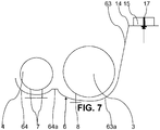
- the W-shape comprises two end branches 63, 64 and two internal branches 63a, 64a respectively associated with an end branch 63, 64.
- the first chute 3 is housed between an end branch 63, 64 and its adjacent internal branch forming a V of the W shape and the second chute 4 is housed between the other end branch 63, 64 and its internal branch. adjacent forming the other V of the W-shape, also called a trigger guard. As the first chute 3 is generally larger in section than the second chute 4, it is common for the two Vs thus formed to be not symmetrical.
- the securing part 6 is fixed respectively with the first and second chutes 3, 4 at at least one respective securing point 7, 8, 9.
- This or these fixings can advantageously be removable. It is not necessary to attach the chutes 3, 4 directly to each other, the securing part 6 doing so indirectly. This is advantageous because the walls of the troughs 3, 4 do not risk being damaged.
- the first and second chutes 3, 4 may be cylindrical, with the first chute 3 of a diameter greater than the second chute 4. At least the internal branch facing the first chute 3, that is- that is to say of the chute having the largest section, may have a rounded shape enveloping less than half of the periphery of the first chute 3.
- the end branch 63, 64 called the first end branch 63 and the internal branch
- said first internal branch 63a associated with the first chute 3 may be of lengths for rectilinear branches or of peripheries for rounded branches which are higher than those respectively of the second end branch 64 and of the second internal branch 64a associated with the second chute 4.
- the W-shape is then asymmetrical, which falls within the scope of the present invention and is most frequent.
- the second end branch 64 associated with the second chute 4 is fixed to the second chute 4 by at least two fixing points 7, the fixings being screws, rivets or points of welding or glue. Removable fasteners such as screws are preferred.
- the second end branch 64 associated with the second flat chute 4 and the second internal branch 64a adjacent to this second end branch 64 of reduced length compared to that of the first end branch 63 associated, this second internal branch 64a pointing towards the first chute 3.
- the second end branch 64 can also be rounded as shown in figure 7 .
- the second end branch 64 associated with the second chute 4 can be flat and of greater width than the other branches of the W-shape for better support of this second end branch 64 against the second chute 4.
- the second end branch 64 may have two round or oblong holes 9a intended respectively for a positioning pin 9 carried by the second chute 4, these round or oblong holes 9a being clearly visible to the figure 2 with one of these holes referenced.
- the first chute 3 may include a stud 8 projecting towards the first internal branch 63a associated with the first chute 3.
- a fixing means 8a can connect the stud 8 to the securing part 6 by passing through the associated first internal branch 63a, the head of the fixing means 8a being on the face of the first internal branch 63a.
- the stud 8 can be only a holding stud without fixing the first chute 6 on the securing part by the first internal branch 63a.
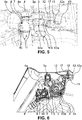
- the W-shaped securing part 6 is delivered assembled and screwed by three screws 7 on the second chute 4, for example an RCS chute and is clipped onto the end portion of the head of the first chute 3, for example the fuel chute via pad 8, advantageously cylindrical and made of plastic.
- the first chute 3 can have a tongue 12 of decreasing width as the tongue 12 moves away from the first chute 3.
- the free end of the tongue 12 can be bent to enter a lumen 13 carried by a free end portion. of the first end branch 63 associated with the first chute 3 and serving as a buttonhole for the free end portion of the first end branch 63 in the form of a finger 12a producing a snap hook.
- the free end portion of the first end branch 63 associated with the first chute 3 is curved by approximately 60 to 100 ° with respect to the rest of the first end branch 63, forming an elbow 14.
- the elbow 14 can be interspersed in below the tongue 12 of curved shape serving as a support for the tongue 12 towards the middle of its length.
- Elbow 14 is particularly visible at figures 6 and 7 .
- the invention also relates to a method of mounting an assembly 10 of at least two reservoirs 1, 2 of consumable fluids on a motor vehicle, the assembly 10 being as described above.
- the second chute 4 of the second tank 2 is pre-assembled with the first chute 3 of the first tank 1 by separately fixing each of the first and second chutes 3, 4 with a connecting piece 6.
- This pre-assembly is followed by the assembly of the assembly 10 on the vehicle. This pre-assembly can be kept once the assembly 10 has been mounted and last for the life of the motor vehicle.
- the invention finally relates to a motor vehicle with such an assembly 10 of at least two reservoirs 1, 2 of consumable fluids.
- the securing part 6 is fixed to a portion of the body reinforcement 15 of the motor vehicle by at least one removable fixing means 7 passing through a free end portion of an end branch 63, 64 of the securing part 6 , advantageously the end portion of the first end branch 63.
- the fixing means 17 is particularly clearly visible to the figures 4 to 7 .
- a first tank 1 can be the fuel tank and the second tank 2 can be the reducing agent tank for a selective catalytic reduction, the fuel tank being of larger capacity than the reducing agent tank or RCS tank.
- the invention finally relates to a motor vehicle comprising such an assembly 10 of at least two reservoirs 1, 2 of consumable fluids, the securing part 6 being fixed to a portion of the body reinforcement 15 of the motor vehicle by at least one means of removable attachment 17 passing through a free end portion of an end branch 63, 64 of the securing part 6.
- This free end portion is advantageously the first end branch 63 associated with the first chute 3.
- This unique screwing has the advantage of reducing the screwing time at the edge of the line and also provides a saving of a screw on the supply side at the edge of the assembly line.
- the first tank 1 can be the fuel tank and the second tank 2 can be the reducing agent tank for selective catalytic reduction.
- an RCS filling chute has an external diameter of 25.5mm and is made of extruded high density polyethylene or HDPE.
- a fuel chute can be HDPE and have a diameter of 40mm. The fuel chute being more robust, the latter is therefore used in terms of support and support for the RCS chute at least in the assembly phase.
Landscapes
- Engineering & Computer Science (AREA)
- Life Sciences & Earth Sciences (AREA)
- Sustainable Development (AREA)
- Sustainable Energy (AREA)
- Chemical & Material Sciences (AREA)
- Combustion & Propulsion (AREA)
- Transportation (AREA)
- Mechanical Engineering (AREA)
- Cooling, Air Intake And Gas Exhaust, And Fuel Tank Arrangements In Propulsion Units (AREA)
Claims (10)
- Baugruppe (10) von mindestens zwei Behältern (1, 2) von Verbrauchsflüssigkeiten für ein Kraftfahrzeug, wobei die Anordnung (10) einen ersten Behälter (1) umfasst, der mit einem ersten Füllschacht (3) und einem zweiten Behälter (2) ausgestattet ist. ausgestattet mit einer zweiten Füllrutsche (4), die sich jeweils in Flüssigkeitsverbindung mit ihrem jeweiligen Vorratsbehälter (1, 2) befindet und über Füllköpfe (3a, 4a) in dieselbe Füllzone mündet, wobei die zweite Rutsche (4) zumindest vorübergehend befestigt ist zur ersten Rutsche (3)in oder in der Nähe der Füllzone durch einen Sicherungsteil (6), der dadurch gekennzeichnet ist, dass der Sicherungsteil (6) W-förmig ist, wobei zwei Endäste (63, 64) bzw. zwei innere Zweige (63a, 64a) zugeordnet sind mit einem Endzweig (63, 64), wobei der erste Schacht (3) zwischen einem ersten Endzweig (63) und einem
ersten benachbarten inneren Zweig (63a) benachbart ist und der zweite Schacht (4) zwischen einem zweiten Endzweig (4) untergebracht
ist (64) und einen benachbarten zweiten internen Zweig (64a), denSicherungsteil (6) wird mit der ersten und zweiten Rutsche (3, 4) an mindestens einem jeweiligen Sicherungspunkt (7, 8, 9) befestigt. - Baugruppe (10) gemäß dem vorhergehenden Anspruch, bei der die erste und die zweite Rutsche (3, 4) zylindrisch sind, wobei die erste Rutsche (3) einen Durchmesser größer als die zweite Rutsche (4) hat, mindestens der erste innere Zweig (63a) gegenüber der ersten Rutsche (3) mit einer abgerundeten Form, die weniger als die Hälfte des Umfangs der ersten Rutsche (3) umhüllt.
- Baugruppe (10) gemäß dem vorhergehenden Anspruch, wobei der erste Endzweig (63) und der erste innere Zweig (63a), die der ersten Rutsche (3) zugeordnet sind, eine größere Länge oder einen größeren Umfang haben als diejenigen des zweiten Endzweigs (64) und des zweiten inneren Zweigs (64a) der der zweiten Rutsche (4) zugeordnet ist, wobei die W-Form asymmetrisch ist.
- Baugruppe (10) gemäß einem der vorhergehenden Ansprüche, wobei der zweite Endast (64), der der zweiten Rutsche (4) zugeordnet ist, durch mindestens zwei Befestigungspunkte (7) an der zweiten Rutsche (4) befestigt ist,wobei die Befestigungselemente Schrauben, Nieten oder Schweiß- oder Klebepunkte sind.
- Baugruppe (10) gemäß dem vorhergehenden Anspruch, bei der die erste Rutsche (3) einen Bolzen (8) umfasst, der in Richtung des ersten inneren Zweigs (63a) vorsteht, der der ersten Rutsche (3) zugeordnet ist, wobei eine Befestigungseinrichtung (8a) die Bolzen (8) zu dem Sicherungsteil (6), der durch den zugehörigen ersten inneren Zweig (63a) verläuft.
- Anordnung (10) gemäß dem vorhergehenden Anspruch, bei der die erste Rutsche (3) eine Zunge (12) mit abnehmender Breite aufweist, wenn sich die Zunge (12) von der ersten Rutsche (3), dem freien Ende der Zunge (12) gekrümmt sein, um in ein Lumen (13) einzutreten, das von einem freien Endabschnitt des ersten Endastes (63) getragen wird, der der ersten Rutsche (3) zugeordnet ist, wobei das freie Ende der Zunge (12) die Form eines Fingers hat (12a) Herstellen eines Karabinerhakens.
- Anordnung (10) gemäß dem vorhergehenden Anspruch, bei der der freie Endabschnitt des ersten Endastes (63), der der ersten Rutsche (3) zugeordnet ist, gegenüber dem Rest des ersten Endastes um ungefähr 60 bis 100° gekrümmt ist (63) Bilden eines Ellbogens (14), wobei der Ellbogen (14) unterhalb der Zunge (12) mit gekrümmter Form angeordnet ist und als Stütze für die Zunge (12) in Richtung der Mitte ihrer Länge dient.
- Verfahren zum Montieren einer Anordnung (10) von mindestens zwei Behältern (1, 2) von Verbrauchsflüssigkeiten an einem Kraftfahrzeug, gekennzeichnet dadurch, dass die Anordnung (10) einem der vorhergehenden Ansprüche entspricht und dass die zweite Rutsche (4) des zweiten Tanks (2) ist mit der ersten Rutsche (3) des ersten Tanks (1) vormontiert, indem jeder der ersten und zweiten Rutschen (3, 4) separat mit einem Sicherungsteil (6) befestigt wird. Auf diese Vormontage folgt die Montage der Baugruppe (10) am Fahrzeug.
- Kraftfahrzeug, dadurch gekennzeichnet, dass es eine Anordnung (10) von mindestens zwei Behältern (1, 2) von Verbrauchsflüssigkeiten nach einem der Ansprüche 1 bis 7 umfasst, wobei der Sicherungsteil (6) an einem Teil der Karosserie befestigt ist Verstärkung (15) des Kraftfahrzeugs
durch entfernbare Befestigungsmittel (17), die durch einen freien Endabschnitt eines Endastes (63) des Sicherungsteils (6) verlaufen. - Kraftfahrzeug nach dem vorhergehenden Anspruch, bei dem ein erster Tank (1) ein Kraftstofftank und ein zweiter Tank (2) ein Reduktionsmitteltank zur selektiven katalytischen Reduktion ist.
Applications Claiming Priority (2)
| Application Number | Priority Date | Filing Date | Title |
|---|---|---|---|
| FR1753237A FR3065187B1 (fr) | 2017-04-13 | 2017-04-13 | Ensemble de deux reservoirs de fluide avec goulottes solidarisees |
| PCT/FR2018/050575 WO2018189439A1 (fr) | 2017-04-13 | 2018-03-12 | Ensemble de deux reservoirs de fluide avec goulottes solidarisees |
Publications (2)
| Publication Number | Publication Date |
|---|---|
| EP3609729A1 EP3609729A1 (de) | 2020-02-19 |
| EP3609729B1 true EP3609729B1 (de) | 2021-04-28 |
Family
ID=58739266
Family Applications (1)
| Application Number | Title | Priority Date | Filing Date |
|---|---|---|---|
| EP18713332.7A Active EP3609729B1 (de) | 2017-04-13 | 2018-03-12 | Anordnung von zwei fluidbehältern mit befestigten rohren |
Country Status (3)
| Country | Link |
|---|---|
| EP (1) | EP3609729B1 (de) |
| FR (1) | FR3065187B1 (de) |
| WO (1) | WO2018189439A1 (de) |
Families Citing this family (1)
| Publication number | Priority date | Publication date | Assignee | Title |
|---|---|---|---|---|
| CN115072202A (zh) * | 2022-06-22 | 2022-09-20 | 一汽奔腾轿车有限公司 | 一种车用固定双排筒型罐的箍带结构 |
Family Cites Families (5)
| Publication number | Priority date | Publication date | Assignee | Title |
|---|---|---|---|---|
| US8167009B2 (en) * | 2008-07-18 | 2012-05-01 | Ford Gobal Technologies, Llc | Adjustable refilling assembly |
| CN204055333U (zh) * | 2014-06-27 | 2014-12-31 | 英瑞杰汽车系统(武汉)有限公司 | 用于机动车储箱的加注阀及机动车储箱组件 |
| FR3031327B1 (fr) * | 2015-01-07 | 2017-07-14 | Peugeot Citroen Automobiles Sa | Dispositif d’inviolabilite de reservoir d’agent reducteur de vehicule automobile |
| FR3034052B1 (fr) * | 2015-03-27 | 2017-03-31 | Peugeot Citroen Automobiles Sa | Ensemble de reservoirs de fluides consommables pour vehicule automobile |
| US9957152B2 (en) * | 2015-05-26 | 2018-05-01 | United States Council For Automotive Research, Llc | Dual-fluid dispensing system and apparatus for diesel vehicle |
-
2017
- 2017-04-13 FR FR1753237A patent/FR3065187B1/fr not_active Expired - Fee Related
-
2018
- 2018-03-12 EP EP18713332.7A patent/EP3609729B1/de active Active
- 2018-03-12 WO PCT/FR2018/050575 patent/WO2018189439A1/fr not_active Ceased
Non-Patent Citations (1)
| Title |
|---|
| None * |
Also Published As
| Publication number | Publication date |
|---|---|
| EP3609729A1 (de) | 2020-02-19 |
| FR3065187B1 (fr) | 2019-04-26 |
| WO2018189439A1 (fr) | 2018-10-18 |
| FR3065187A1 (fr) | 2018-10-19 |
Similar Documents
| Publication | Publication Date | Title |
|---|---|---|
| WO2016156686A1 (fr) | Ensemble de réservoirs de fluides consommables pour véhicule automobile | |
| EP3609729B1 (de) | Anordnung von zwei fluidbehältern mit befestigten rohren | |
| FR2942289A1 (fr) | Agrafe de fixation amovible d'une canalisation sur un support | |
| FR2916711A1 (fr) | Agencement de retenue de bagages pour vehicule automobile | |
| FR2934830A1 (fr) | Structure de fixation d'entree de lave-glace | |
| WO2004005116A1 (fr) | Element structurel comprenant un ecrou de fixation a un montant et vehicule automobile correspondant | |
| FR3070326B1 (fr) | Ensemble d’une goulotte de carburant et d’une goulotte d’un agent liquide solidarisees ensemble | |
| FR2761626A1 (fr) | Procede d'assemblage par soudage de pieces de tolerie | |
| EP4396044A1 (de) | Einteiliger arm eines wischsystems mit mehreren längsträgern | |
| WO2012084841A1 (fr) | Dispositif de maintien d'element(s) allonge(s) | |
| EP3312053B1 (de) | Befestigungsanordnung für aufklappbegrenzung einer hinteren ablage auf der heckklappe eines kraftfahrzeugs | |
| FR3055391B1 (fr) | Dispositif de maintien de conduites associees a un reservoir de vehicule automobile | |
| EP3375675B1 (de) | Abdeckung, verbindungsvorrichtung für die montage eines scheibenwischerblatts auf einem entsprechenden scheibenwischerarm, und entsprechendes scheibenwischsystem | |
| BE1032552B1 (fr) | Réservoir à carburant en matière plastique pour véhicule automobile | |
| EP4370818B1 (de) | Vorrichtung zur befestigung eines elements an einem teil eines kraftfahrzeugs | |
| FR2953176A1 (fr) | Piece de revetement | |
| FR2820372A1 (fr) | Dispositif anti-siphonnage | |
| EP3847049A1 (de) | Vorrichtung zum verbinden von rohrköpfen von tanks und kraftfahrzeug mit einer solchen vorrichtung | |
| FR2848622A1 (fr) | Procede de fixation etanche d'un panneau sur un element de carrosserie d'un vehicule et dispositif correspondant | |
| EP1637747B1 (de) | Anordnung zur Festlegung eines Ausstattungselements für ein Kraftfahrzeug | |
| FR2833525A1 (fr) | Agencement pour la fixation sur un longeron creux d'un organe d'attelage a un element de remorquage, ou d'arrimage, d'un vehicule automobile | |
| FR3150561A1 (fr) | Dispositif de support pour au moins un tuyau destiné à équiper un véhicule automobile | |
| FR3137340A1 (fr) | Ensemble de peau pare-chocs de véhicule automobile avec clip de montage | |
| EP4701917A1 (de) | Kotflügel eines kraftfahrzeugs und anordnung eines solchen kotflügels und eines flüssigkeitstanks | |
| FR2935127A1 (fr) | Piece de rehausse pour l'assemblage de la caisse d'un vehicule sur une partie de soubassement et son utilisation |
Legal Events
| Date | Code | Title | Description |
|---|---|---|---|
| STAA | Information on the status of an ep patent application or granted ep patent |
Free format text: STATUS: UNKNOWN |
|
| STAA | Information on the status of an ep patent application or granted ep patent |
Free format text: STATUS: THE INTERNATIONAL PUBLICATION HAS BEEN MADE |
|
| PUAI | Public reference made under article 153(3) epc to a published international application that has entered the european phase |
Free format text: ORIGINAL CODE: 0009012 |
|
| STAA | Information on the status of an ep patent application or granted ep patent |
Free format text: STATUS: REQUEST FOR EXAMINATION WAS MADE |
|
| 17P | Request for examination filed |
Effective date: 20190916 |
|
| AK | Designated contracting states |
Kind code of ref document: A1 Designated state(s): AL AT BE BG CH CY CZ DE DK EE ES FI FR GB GR HR HU IE IS IT LI LT LU LV MC MK MT NL NO PL PT RO RS SE SI SK SM TR |
|
| AX | Request for extension of the european patent |
Extension state: BA ME |
|
| DAX | Request for extension of the european patent (deleted) | ||
| RAV | Requested validation state of the european patent: fee paid |
Extension state: MA Effective date: 20190916 |
|
| GRAP | Despatch of communication of intention to grant a patent |
Free format text: ORIGINAL CODE: EPIDOSNIGR1 |
|
| RAP1 | Party data changed (applicant data changed or rights of an application transferred) |
Owner name: PSA AUTOMOBILES SA |
|
| STAA | Information on the status of an ep patent application or granted ep patent |
Free format text: STATUS: GRANT OF PATENT IS INTENDED |
|
| INTG | Intention to grant announced |
Effective date: 20201112 |
|
| GRAS | Grant fee paid |
Free format text: ORIGINAL CODE: EPIDOSNIGR3 |
|
| GRAA | (expected) grant |
Free format text: ORIGINAL CODE: 0009210 |
|
| STAA | Information on the status of an ep patent application or granted ep patent |
Free format text: STATUS: THE PATENT HAS BEEN GRANTED |
|
| AK | Designated contracting states |
Kind code of ref document: B1 Designated state(s): AL AT BE BG CH CY CZ DE DK EE ES FI FR GB GR HR HU IE IS IT LI LT LU LV MC MK MT NL NO PL PT RO RS SE SI SK SM TR |
|
| REG | Reference to a national code |
Ref country code: GB Ref legal event code: FG4D Free format text: NOT ENGLISH Ref country code: DE Ref legal event code: R084 Ref document number: 602018016219 Country of ref document: DE |
|
| REG | Reference to a national code |
Ref country code: CH Ref legal event code: EP |
|
| REG | Reference to a national code |
Ref country code: AT Ref legal event code: REF Ref document number: 1386691 Country of ref document: AT Kind code of ref document: T Effective date: 20210515 |
|
| REG | Reference to a national code |
Ref country code: DE Ref legal event code: R096 Ref document number: 602018016219 Country of ref document: DE |
|
| REG | Reference to a national code |
Ref country code: IE Ref legal event code: FG4D Free format text: LANGUAGE OF EP DOCUMENT: FRENCH |
|
| REG | Reference to a national code |
Ref country code: GB Ref legal event code: 746 Effective date: 20210705 |
|
| REG | Reference to a national code |
Ref country code: LT Ref legal event code: MG9D |
|
| REG | Reference to a national code |
Ref country code: AT Ref legal event code: MK05 Ref document number: 1386691 Country of ref document: AT Kind code of ref document: T Effective date: 20210428 |
|
| PG25 | Lapsed in a contracting state [announced via postgrant information from national office to epo] |
Ref country code: NL Free format text: LAPSE BECAUSE OF FAILURE TO SUBMIT A TRANSLATION OF THE DESCRIPTION OR TO PAY THE FEE WITHIN THE PRESCRIBED TIME-LIMIT Effective date: 20210428 Ref country code: AT Free format text: LAPSE BECAUSE OF FAILURE TO SUBMIT A TRANSLATION OF THE DESCRIPTION OR TO PAY THE FEE WITHIN THE PRESCRIBED TIME-LIMIT Effective date: 20210428 Ref country code: BG Free format text: LAPSE BECAUSE OF FAILURE TO SUBMIT A TRANSLATION OF THE DESCRIPTION OR TO PAY THE FEE WITHIN THE PRESCRIBED TIME-LIMIT Effective date: 20210728 Ref country code: FI Free format text: LAPSE BECAUSE OF FAILURE TO SUBMIT A TRANSLATION OF THE DESCRIPTION OR TO PAY THE FEE WITHIN THE PRESCRIBED TIME-LIMIT Effective date: 20210428 Ref country code: LT Free format text: LAPSE BECAUSE OF FAILURE TO SUBMIT A TRANSLATION OF THE DESCRIPTION OR TO PAY THE FEE WITHIN THE PRESCRIBED TIME-LIMIT Effective date: 20210428 Ref country code: HR Free format text: LAPSE BECAUSE OF FAILURE TO SUBMIT A TRANSLATION OF THE DESCRIPTION OR TO PAY THE FEE WITHIN THE PRESCRIBED TIME-LIMIT Effective date: 20210428 |
|
| PG25 | Lapsed in a contracting state [announced via postgrant information from national office to epo] |
Ref country code: SE Free format text: LAPSE BECAUSE OF FAILURE TO SUBMIT A TRANSLATION OF THE DESCRIPTION OR TO PAY THE FEE WITHIN THE PRESCRIBED TIME-LIMIT Effective date: 20210428 Ref country code: PT Free format text: LAPSE BECAUSE OF FAILURE TO SUBMIT A TRANSLATION OF THE DESCRIPTION OR TO PAY THE FEE WITHIN THE PRESCRIBED TIME-LIMIT Effective date: 20210830 Ref country code: RS Free format text: LAPSE BECAUSE OF FAILURE TO SUBMIT A TRANSLATION OF THE DESCRIPTION OR TO PAY THE FEE WITHIN THE PRESCRIBED TIME-LIMIT Effective date: 20210428 Ref country code: NO Free format text: LAPSE BECAUSE OF FAILURE TO SUBMIT A TRANSLATION OF THE DESCRIPTION OR TO PAY THE FEE WITHIN THE PRESCRIBED TIME-LIMIT Effective date: 20210728 Ref country code: LV Free format text: LAPSE BECAUSE OF FAILURE TO SUBMIT A TRANSLATION OF THE DESCRIPTION OR TO PAY THE FEE WITHIN THE PRESCRIBED TIME-LIMIT Effective date: 20210428 Ref country code: PL Free format text: LAPSE BECAUSE OF FAILURE TO SUBMIT A TRANSLATION OF THE DESCRIPTION OR TO PAY THE FEE WITHIN THE PRESCRIBED TIME-LIMIT Effective date: 20210428 Ref country code: GR Free format text: LAPSE BECAUSE OF FAILURE TO SUBMIT A TRANSLATION OF THE DESCRIPTION OR TO PAY THE FEE WITHIN THE PRESCRIBED TIME-LIMIT Effective date: 20210729 Ref country code: IS Free format text: LAPSE BECAUSE OF FAILURE TO SUBMIT A TRANSLATION OF THE DESCRIPTION OR TO PAY THE FEE WITHIN THE PRESCRIBED TIME-LIMIT Effective date: 20210828 |
|
| REG | Reference to a national code |
Ref country code: NL Ref legal event code: MP Effective date: 20210428 |
|
| PG25 | Lapsed in a contracting state [announced via postgrant information from national office to epo] |
Ref country code: DK Free format text: LAPSE BECAUSE OF FAILURE TO SUBMIT A TRANSLATION OF THE DESCRIPTION OR TO PAY THE FEE WITHIN THE PRESCRIBED TIME-LIMIT Effective date: 20210428 Ref country code: CZ Free format text: LAPSE BECAUSE OF FAILURE TO SUBMIT A TRANSLATION OF THE DESCRIPTION OR TO PAY THE FEE WITHIN THE PRESCRIBED TIME-LIMIT Effective date: 20210428 Ref country code: RO Free format text: LAPSE BECAUSE OF FAILURE TO SUBMIT A TRANSLATION OF THE DESCRIPTION OR TO PAY THE FEE WITHIN THE PRESCRIBED TIME-LIMIT Effective date: 20210428 Ref country code: ES Free format text: LAPSE BECAUSE OF FAILURE TO SUBMIT A TRANSLATION OF THE DESCRIPTION OR TO PAY THE FEE WITHIN THE PRESCRIBED TIME-LIMIT Effective date: 20210428 Ref country code: EE Free format text: LAPSE BECAUSE OF FAILURE TO SUBMIT A TRANSLATION OF THE DESCRIPTION OR TO PAY THE FEE WITHIN THE PRESCRIBED TIME-LIMIT Effective date: 20210428 Ref country code: SK Free format text: LAPSE BECAUSE OF FAILURE TO SUBMIT A TRANSLATION OF THE DESCRIPTION OR TO PAY THE FEE WITHIN THE PRESCRIBED TIME-LIMIT Effective date: 20210428 Ref country code: SM Free format text: LAPSE BECAUSE OF FAILURE TO SUBMIT A TRANSLATION OF THE DESCRIPTION OR TO PAY THE FEE WITHIN THE PRESCRIBED TIME-LIMIT Effective date: 20210428 |
|
| REG | Reference to a national code |
Ref country code: DE Ref legal event code: R097 Ref document number: 602018016219 Country of ref document: DE |
|
| PLBE | No opposition filed within time limit |
Free format text: ORIGINAL CODE: 0009261 |
|
| STAA | Information on the status of an ep patent application or granted ep patent |
Free format text: STATUS: NO OPPOSITION FILED WITHIN TIME LIMIT |
|
| 26N | No opposition filed |
Effective date: 20220131 |
|
| PG25 | Lapsed in a contracting state [announced via postgrant information from national office to epo] |
Ref country code: IS Free format text: LAPSE BECAUSE OF FAILURE TO SUBMIT A TRANSLATION OF THE DESCRIPTION OR TO PAY THE FEE WITHIN THE PRESCRIBED TIME-LIMIT Effective date: 20210828 Ref country code: AL Free format text: LAPSE BECAUSE OF FAILURE TO SUBMIT A TRANSLATION OF THE DESCRIPTION OR TO PAY THE FEE WITHIN THE PRESCRIBED TIME-LIMIT Effective date: 20210428 |
|
| PG25 | Lapsed in a contracting state [announced via postgrant information from national office to epo] |
Ref country code: IT Free format text: LAPSE BECAUSE OF FAILURE TO SUBMIT A TRANSLATION OF THE DESCRIPTION OR TO PAY THE FEE WITHIN THE PRESCRIBED TIME-LIMIT Effective date: 20210428 |
|
| PG25 | Lapsed in a contracting state [announced via postgrant information from national office to epo] |
Ref country code: MC Free format text: LAPSE BECAUSE OF FAILURE TO SUBMIT A TRANSLATION OF THE DESCRIPTION OR TO PAY THE FEE WITHIN THE PRESCRIBED TIME-LIMIT Effective date: 20210428 |
|
| REG | Reference to a national code |
Ref country code: CH Ref legal event code: PL |
|
| REG | Reference to a national code |
Ref country code: BE Ref legal event code: MM Effective date: 20220331 |
|
| PG25 | Lapsed in a contracting state [announced via postgrant information from national office to epo] |
Ref country code: LU Free format text: LAPSE BECAUSE OF NON-PAYMENT OF DUE FEES Effective date: 20220312 Ref country code: LI Free format text: LAPSE BECAUSE OF NON-PAYMENT OF DUE FEES Effective date: 20220331 Ref country code: IE Free format text: LAPSE BECAUSE OF NON-PAYMENT OF DUE FEES Effective date: 20220312 Ref country code: CH Free format text: LAPSE BECAUSE OF NON-PAYMENT OF DUE FEES Effective date: 20220331 |
|
| PG25 | Lapsed in a contracting state [announced via postgrant information from national office to epo] |
Ref country code: BE Free format text: LAPSE BECAUSE OF NON-PAYMENT OF DUE FEES Effective date: 20220331 |
|
| REG | Reference to a national code |
Ref country code: DE Ref legal event code: R081 Ref document number: 602018016219 Country of ref document: DE Owner name: STELLANTIS AUTO SAS, FR Free format text: FORMER OWNER: PSA AUTOMOBILES SA, POISSY, FR |
|
| PG25 | Lapsed in a contracting state [announced via postgrant information from national office to epo] |
Ref country code: MK Free format text: LAPSE BECAUSE OF FAILURE TO SUBMIT A TRANSLATION OF THE DESCRIPTION OR TO PAY THE FEE WITHIN THE PRESCRIBED TIME-LIMIT Effective date: 20210428 Ref country code: CY Free format text: LAPSE BECAUSE OF FAILURE TO SUBMIT A TRANSLATION OF THE DESCRIPTION OR TO PAY THE FEE WITHIN THE PRESCRIBED TIME-LIMIT Effective date: 20210428 |
|
| VS25 | Lapsed in a validation state [announced via postgrant information from nat. office to epo] |
Ref country code: MA Free format text: LAPSE BECAUSE OF FAILURE TO SUBMIT A TRANSLATION OF THE DESCRIPTION OR TO PAY THE FEE WITHIN THE PRESCRIBED TIME-LIMIT Effective date: 20210428 |
|
| PG25 | Lapsed in a contracting state [announced via postgrant information from national office to epo] |
Ref country code: HU Free format text: LAPSE BECAUSE OF FAILURE TO SUBMIT A TRANSLATION OF THE DESCRIPTION OR TO PAY THE FEE WITHIN THE PRESCRIBED TIME-LIMIT; INVALID AB INITIO Effective date: 20180312 |
|
| PG25 | Lapsed in a contracting state [announced via postgrant information from national office to epo] |
Ref country code: MT Free format text: LAPSE BECAUSE OF FAILURE TO SUBMIT A TRANSLATION OF THE DESCRIPTION OR TO PAY THE FEE WITHIN THE PRESCRIBED TIME-LIMIT Effective date: 20210428 |
|
| PG25 | Lapsed in a contracting state [announced via postgrant information from national office to epo] |
Ref country code: TR Free format text: LAPSE BECAUSE OF FAILURE TO SUBMIT A TRANSLATION OF THE DESCRIPTION OR TO PAY THE FEE WITHIN THE PRESCRIBED TIME-LIMIT Effective date: 20210428 |
|
| PGFP | Annual fee paid to national office [announced via postgrant information from national office to epo] |
Ref country code: GB Payment date: 20260219 Year of fee payment: 9 |
|
| PGFP | Annual fee paid to national office [announced via postgrant information from national office to epo] |
Ref country code: DE Payment date: 20260219 Year of fee payment: 9 |
|
| PGFP | Annual fee paid to national office [announced via postgrant information from national office to epo] |
Ref country code: FR Payment date: 20260219 Year of fee payment: 9 |