EP3609740B1 - Dispositif pour le support d'un véhicule à deux roues sur un élément de structure - Google Patents
Dispositif pour le support d'un véhicule à deux roues sur un élément de structure Download PDFInfo
- Publication number
- EP3609740B1 EP3609740B1 EP19700194.4A EP19700194A EP3609740B1 EP 3609740 B1 EP3609740 B1 EP 3609740B1 EP 19700194 A EP19700194 A EP 19700194A EP 3609740 B1 EP3609740 B1 EP 3609740B1
- Authority
- EP
- European Patent Office
- Prior art keywords
- fork
- elements
- wheeler
- recesses
- wheeled vehicle
- Prior art date
- Legal status (The legal status is an assumption and is not a legal conclusion. Google has not performed a legal analysis and makes no representation as to the accuracy of the status listed.)
- Active
Links
Images

Classifications
-
- B—PERFORMING OPERATIONS; TRANSPORTING
- B60—VEHICLES IN GENERAL
- B60P—VEHICLES ADAPTED FOR LOAD TRANSPORTATION OR TO TRANSPORT, TO CARRY, OR TO COMPRISE SPECIAL LOADS OR OBJECTS
- B60P3/00—Vehicles adapted to transport, to carry or to comprise special loads or objects
- B60P3/06—Vehicles adapted to transport, to carry or to comprise special loads or objects for carrying vehicles
- B60P3/07—Vehicles adapted to transport, to carry or to comprise special loads or objects for carrying vehicles for carrying road vehicles
- B60P3/073—Vehicle retainers
- B60P3/075—Vehicle retainers for wheels, hubs, or axle shafts
-
- B—PERFORMING OPERATIONS; TRANSPORTING
- B62—LAND VEHICLES FOR TRAVELLING OTHERWISE THAN ON RAILS
- B62H—CYCLE STANDS; SUPPORTS OR HOLDERS FOR PARKING OR STORING CYCLES; APPLIANCES PREVENTING OR INDICATING UNAUTHORIZED USE OR THEFT OF CYCLES; LOCKS INTEGRAL WITH CYCLES; DEVICES FOR LEARNING TO RIDE CYCLES
- B62H3/00—Separate supports or holders for parking or storing cycles
- B62H3/04—Separate supports or holders for parking or storing cycles involving forked supports of brackets for holding a wheel
-
- B—PERFORMING OPERATIONS; TRANSPORTING
- B60—VEHICLES IN GENERAL
- B60P—VEHICLES ADAPTED FOR LOAD TRANSPORTATION OR TO TRANSPORT, TO CARRY, OR TO COMPRISE SPECIAL LOADS OR OBJECTS
- B60P3/00—Vehicles adapted to transport, to carry or to comprise special loads or objects
- B60P3/06—Vehicles adapted to transport, to carry or to comprise special loads or objects for carrying vehicles
- B60P3/07—Vehicles adapted to transport, to carry or to comprise special loads or objects for carrying vehicles for carrying road vehicles
-
- B—PERFORMING OPERATIONS; TRANSPORTING
- B62—LAND VEHICLES FOR TRAVELLING OTHERWISE THAN ON RAILS
- B62H—CYCLE STANDS; SUPPORTS OR HOLDERS FOR PARKING OR STORING CYCLES; APPLIANCES PREVENTING OR INDICATING UNAUTHORIZED USE OR THEFT OF CYCLES; LOCKS INTEGRAL WITH CYCLES; DEVICES FOR LEARNING TO RIDE CYCLES
- B62H3/00—Separate supports or holders for parking or storing cycles
- B62H3/08—Separate supports or holders for parking or storing cycles involving recesses or channelled rails for embracing the bottom part of a wheel
Definitions
- the invention relates to a device for holding a two-wheeler on a structural part and to a transport device for a two-wheeler.
- the loading of the two-wheelers is usually associated with a lot of effort, since they have to be connected to the transport vehicle in a reliable manner in order to prevent damage during transport.
- the most varied of solutions for this are known from the prior art.
- This pressure is transferred directly to the sealing elements, in this case the oil seals, and leads to a leak in the event of permanent stress, such as during long transport. This is particularly annoying if it is only discovered at the destination, where repairs to the two-wheeler may not be possible or only at very high cost, so that a planned vacation may not take place. In particular, if such a transport of the two-wheeler takes place commercially, this can lead to considerable problems.
- the DE 20 2017 003 076 U1 describes a rollable and adjustable motorcycle loading aid with which the motorcycle is picked up by its two wheels.
- a similar solution is also from the DE 10 2008 060 527 A1 known.
- a fundamental problem with the inclusion of a two-wheeler in the area of the wheels, however, is that due to the height of the two-wheeler with the corresponding force, for example when the transport vehicle is cornering, there is a considerable overturning moment, which means that safe transport of the two-wheeler is practically impossible.
- the FR 2 642 378 A1 describes a device with an adjustable chassis attached to a trailer and adaptable to the size of a motorcycle.
- a motorcycle stand for storing or transporting a motorcycle in an immovable upright position. This has a stand base that is connected to an axle support post.
- the device according to the invention offers significant advantages over known solutions.
- the fork receiving element ensures a secure connection of the device to the two-wheeler, with the two-wheeler being held in the area of the fork and the associated possibility of a high force application point ensuring that the two-wheeler cannot tip over even with high forces acting on it. This is supported by the devices used to attach the lashing elements, which can also be located in an upper area of the two-wheeled vehicle, which additionally prevents the same from tipping over.
- the reliable and safe reception of the two-wheeler by the device according to the invention is supported by the axle support element, since this enables a rigid connection between the device and the two-wheeler so that correspondingly high forces can be absorbed.
- the connecting elements ensure the connection between the fork receiving element and the axle support element and thus complete the device designed in the form of a frame.
- the devices for attaching the lashing elements are arranged on the connecting elements. As a result, a sufficient distance can be created between the devices for attaching the lashing elements and the axle support element, so that the two-wheeler can be securely connected to the corresponding structural part.
- the connecting elements have respective projections on which the devices for attaching the lashing elements are arranged, it is possible on the one hand to make the connecting elements sufficiently narrow and thus light and on the other hand to ensure sufficient strength in the areas important for the function of the device.
- the devices for attaching the lashing elements are designed as recesses.
- the lashing elements can be hooked into the recesses in this way, for example by means of appropriate hooks or the like.
- the fork receiving element is designed in two parts and the recesses for receiving the fork of the two-wheeler are each semicircular, there is a simple possibility for mounting the fork receiving element on the fork.
- the fork receiving element is connected to the connecting elements by means of respective connecting bolts. This enables simple assembly of the connecting elements on the fork receiving element and a secure connection of these components.
- axle support element results when it is designed as a bolt that can be passed through the axle of the two-wheeler. In this way, simple assembly of the device is also possible.
- axle support element can be locked in its position by means of respective locking pins. This enables the device to be securely fixed in its position holding the two-wheeler in a simple manner.
- a further adaptation of the device to different configurations of two-wheelers can result if the connecting elements have respective recesses for adapting to the shape of the fork of the two-wheeler.
- Another advantageous embodiment of the invention can consist in that at least the fork receiving element and the connecting elements consist of an aluminum material. As a result, a light, robust and corrosion-protected design of the device is achieved.
- Claim 15 specifies a transport device for a two-wheeled vehicle with a chassis, a structural part and a device according to the invention.
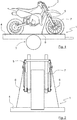
- Fig. 1 shows a transport device 1 for a two-wheeler 2, which has a chassis 3, a structural part 4 and a device 5 for holding the two-wheeler 2 on the structural part 4.
- the transport device 1 is a trailer, but it would also be possible to use a small transporter, a rail vehicle or the like as the transport device 1.
- the structural part 4 is designed as a base plate of the transport device 1.
- the two-wheeler 2 can also be attached to a lifting platform or the like with the device 5.
- the two-wheeler 2 which in this case is designed as an off-road motorcycle, is only to be regarded as an example and in principle any two-wheeler 2 can be attached to the structural part 4 with the device 5, whereby corresponding adaptations of the device 5 may be necessary.
- the device 5 is secured by means of several lashing elements 6, of which in Fig. 1 one is shown, connected to the structural part 4.
- Fig. 2 a schematic front view of the transport device 1 is shown, from which the arrangement of the device 5 relative to a fork 7 of the two-wheeler 2 can be seen.
- the point of application of the lashing elements 6, of which two are preferably provided, ie one on each side of the two-wheeler 2, is in the Figures 1 and 2 to recognize.
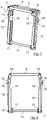
- the device 5 is shown in detail with its individual components.
- the device 5 has in its upper region a fork receiving element 8 which is in the Figures 3 , 6 and 7 has recognizable recesses 9 which are used to receive the fork 7 of the two-wheeler 2.
- the fork receiving element 8 is, as in particular in Fig. 5 can be seen, is designed in two parts and the recesses 9 are each semicircular, so that when the two parts of the fork receiving element 8 are arranged side by side, as in FIG Fig. 7 shown, result in two circular recesses 9 through which the fork 7 can be passed.
- Protective elements can be located in the recesses 9 in the fork receiving element 8, which elements can consist of felt, for example, and can be glued to the fork receiving element 8. Due to the protective elements, the fork receiving element 8 can be attached to the fork 7 without play and damage to the fork 7 is avoided at the same time.
- an axle support element 10 which serves to support the device 5 on an axle (not shown) of the front wheel of the two-wheeler 2.
- the axle is a hollow axle through which the axle support element 10, designed as a bolt, is passed.
- the axle support element can be locked in its position on both sides by means of respective locking pins 11 implemented in the same through corresponding bores.
- two vertically extending connecting elements 12 are used, which in the present case have recesses 13 designed as through-holes for receiving or, in the present case, for guiding the axle support element 10 through.
- the connecting elements 12 can be connected to the fork receiving element 8 on their upper side by means of respective connecting bolts 14.
- the connecting bolts 14 are preferably secured by means of respective locking pins, not shown.
- the securing pins for securing the connecting bolts 14 can be designed similarly to the securing pins 11 with which the axle support element 10 is locked in its position.
- screws can also be used can be used to connect the connecting elements 12 to the fork receiving elements 8.
- the use of the connecting bolts 14, however, enables the device 5 to be easily mounted on the two-wheeler 2.
- the connecting elements 12 On the connecting elements 12, respective devices 15 for attaching the lashing elements 6 are arranged.
- the devices 15 are arranged at a distance from the recesses 12 for leading the axle support element 10 through. As a result, a sufficiently high force application point of the lashing elements 6 on the device 5 is achieved.
- the connecting elements 12 have respective projections 16 in which the devices 15 for attaching the lashing elements 6 are arranged.
- the devices 15 are recesses into which hooks arranged on the lashing elements 6 can be inserted, for example.
- the devices 15 are arranged on the connecting elements 12, since the connecting elements 12 are particularly easily accessible. In principle, however, it would also be possible to attach the devices 15 for attaching the lashing elements 6 to the fork receiving element 8.
- respective spacer elements 17 are arranged to rest against the connecting elements 12 on the one hand and on the fork 7 of the two-wheeler 2 on the other hand.
- the connecting elements 12 have recesses 18 for adaptation to the shape of the fork 7 of the two-wheeler 2.
- the size and shape of the recesses 18 can be selected so that the connecting elements 12 are at a sufficient distance from the fork 7.
- the dimensions of the other components of the device 5 can also be adapted to different sizes or shapes of the respective two-wheeler 2.
- the device 5 can be used for very sporty-oriented motorcycles, which are mainly driven on racetracks, for so-called naked bikes or also for off-road or cross motorcycles.
- the outer diameter of the axle support element 10 can optionally be adapted to the inner diameter of the axle of the two-wheeler 2.
- the fork receiving element 8, the connecting elements 12 and possibly also the axle support element 10 can consist of an aluminum material. Of course, other materials can also be used for this.
- all parts of the device 5 are manufactured from a solid material by means of milling, but it would in principle also be possible to manufacture these parts by means of die casting or another suitable method. A combination of several methods is of course also conceivable.
Landscapes
- Engineering & Computer Science (AREA)
- Mechanical Engineering (AREA)
- Health & Medical Sciences (AREA)
- Public Health (AREA)
- Transportation (AREA)
- Packaging Of Machine Parts And Wound Products (AREA)
- Fittings On The Vehicle Exterior For Carrying Loads, And Devices For Holding Or Mounting Articles (AREA)
- Motorcycle And Bicycle Frame (AREA)
Claims (15)
- Dispositif (5) pour le support d'un véhicule à deux roues (2) sur un élément de structure (4), comprenant les caractéristiques suivantes :- un élément de réception de fourche (8) qui comporte des évidements (9) destinés à recevoir une fourche (7) du véhicule à deux roues (2), et- un élément de support d'essieu (10) pour supporter un essieu du véhicule à deux roues (2),caractérisé par :- au moins deux éléments de liaison (12) pour relier l'élément de réception de fourche (8) à l'élément de support d'essieu (10) et qui comportent des évidements respectifs (13) destinés à recevoir l'élément de support d'essieu (10), et- au moins deux dispositifs (15) espacés des évidements (13) destinés à recevoir l'élément de support d'essieu (10) pour appliquer des éléments de serrage (6) à l'aide desquels le dispositif (5) peut être assemblé à l'élément de structure (4).
- Dispositif selon la revendication 1, caractérisé en ce que les dispositifs (15) destinés à appliquer les éléments de serrage (6) sont disposés sur les éléments de liaison (12).
- Dispositif selon la revendication 2, caractérisé en ce que les éléments de liaison (12) comportent des saillies respectives (16) sur lesquelles les dispositifs (15) destinés à appliquer les éléments de serrage (6) sont disposés.
- Dispositif selon la revendication 1, 2 ou 3, caractérisé en ce que les dispositifs (15) destinés à appliquer les éléments de serrage (6) sont réalisés sous la forme d'évidements.
- Dispositif selon l'une quelconque des revendications 1 à 4, caractérisé en ce que l'élément de réception de fourche (8) est réalisé en deux parties, dans lequel les évidements (9) destinés à recevoir la fourche (7) du véhicule à deux roues (2) sont chacun de forme semi-circulaire.
- Dispositif selon l'une quelconque des revendications 1 à 5, caractérisé en ce que l'élément de réception de fourche (8) est assemblé aux éléments de liaison (12) à l'aide de boulons d'assemblage respectifs (14).
- Dispositif selon la revendication 6, caractérisé en ce que les boulons de liaison (14) sont bloqués à l'aide de tiges de blocage respectives.
- Dispositif selon l'une quelconque des revendications 1 à 7, caractérisé en ce que l'élément de support d'essieu (10) peut être introduit à travers l'essieu du véhicule à deux roues (2).
- Dispositif selon la revendication 8, caractérisé en ce que l'élément de support d'essieu (10) peut être bloqué dans sa position à l'aide de tiges de blocage respectives (11).
- Dispositif selon la revendication 8 ou 9, caractérisé en ce que des éléments d'écartement (17) sont disposés sur l'élément de support d'essieu (10) en vue de l'appui sur les éléments de liaison (12) et sur la fourche (7) du véhicule à deux roues (2).
- Dispositif selon l'une quelconque des revendications 1 à 10, caractérisé en ce que des éléments de protection respectifs sont disposés dans les évidements (9) dans l'élément de réception de fourche (8).
- Dispositif selon la revendication 11, caractérisé en ce que les éléments de protection sont constitués de feutre et sont collés à l'élément de réception de fourche (8).
- Dispositif selon l'une quelconque des revendications 1 à 12, caractérisé en ce que les éléments de liaison (12) présentent des découpes respectives (18) pour l'adaptation à la forme de la fourche (7) du véhicule à deux roues (2).
- Dispositif selon l'une quelconque des revendications 1 à 13, caractérisé en ce qu'au moins l'élément de réception de fourche (8) et les éléments de liaison (12) sont constitués d'un matériau à base d'aluminium.
- Dispositif de transport (1) pour un véhicule à deux roues (2) comprenant un châssis (3), un élément de structure (4) et un dispositif (5) selon l'une quelconque des revendications 1 à 14 et comprenant des éléments de serrage (6) qui sont en prise avec les dispositifs (15) destinés à appliquer ceux-ci et par l'intermédiaire desquels le dispositif (5) est relié à l'élément de structure (4).
Applications Claiming Priority (2)
| Application Number | Priority Date | Filing Date | Title |
|---|---|---|---|
| DE202018100033.0U DE202018100033U1 (de) | 2018-01-03 | 2018-01-03 | Vorrichtung zur Halterung eines Zweirads an einem Strukturteil |
| PCT/EP2019/050009 WO2019134901A1 (fr) | 2018-01-03 | 2019-01-02 | Dispositif pour le support d'un véhicule à deux roues sur un élément de structure |
Publications (3)
| Publication Number | Publication Date |
|---|---|
| EP3609740A1 EP3609740A1 (fr) | 2020-02-19 |
| EP3609740B1 true EP3609740B1 (fr) | 2020-08-26 |
| EP3609740B8 EP3609740B8 (fr) | 2020-11-11 |
Family
ID=61525812
Family Applications (1)
| Application Number | Title | Priority Date | Filing Date |
|---|---|---|---|
| EP19700194.4A Active EP3609740B8 (fr) | 2018-01-03 | 2019-01-02 | Dispositif pour le support d'un véhicule à deux roues sur un élément de structure |
Country Status (5)
| Country | Link |
|---|---|
| US (1) | US11383778B2 (fr) |
| EP (1) | EP3609740B8 (fr) |
| DE (1) | DE202018100033U1 (fr) |
| ES (1) | ES2834647T3 (fr) |
| WO (1) | WO2019134901A1 (fr) |
Families Citing this family (2)
| Publication number | Priority date | Publication date | Assignee | Title |
|---|---|---|---|---|
| DE102022104407A1 (de) | 2022-02-24 | 2023-08-24 | Bayerische Motoren Werke Aktiengesellschaft | Haltevorrichtung zum Halten eines Zweirads auf einem Untergrund |
| DE102022108128A1 (de) | 2022-04-05 | 2023-10-05 | Bayerische Motoren Werke Aktiengesellschaft | Haltevorrichtung zum Halten eines Zweirads auf einem Untergrund |
Family Cites Families (10)
| Publication number | Priority date | Publication date | Assignee | Title |
|---|---|---|---|---|
| US4441736A (en) * | 1982-05-12 | 1984-04-10 | Shedden Joel T | Device for reducing wear in vehicle suspension systems |
| FR2642378B1 (fr) * | 1989-02-02 | 1991-06-14 | Bockler Didier | Dispositif de fixation rapide de motocyclettes sur une remorque de transport |
| US8485369B2 (en) * | 2007-12-18 | 2013-07-16 | Woodrow Loyd Glover | Motorcycle stand |
| AT505287B1 (de) | 2008-02-12 | 2008-12-15 | Oebb Personenverkehr Ag | Motorradbefestigung |
| DE102008060527A1 (de) | 2008-12-04 | 2010-04-29 | Daimler Ag | Haltevorrichtung und Anordnung einer Haltevorrichtung zur Halterung eines Rades, insbesondere eines Kraftrades, an einem Ladeboden eines Fahrzeugs |
| US8517343B1 (en) * | 2012-02-07 | 2013-08-27 | Pit Bull Products, Inc. | Dual purpose front motorcycle stand |
| DE102012101192A1 (de) * | 2012-02-15 | 2013-08-22 | Matthias Müller | Anordnung zum Festhalten eines Zweiradfahrzeugs auf einem Transportfahrzeug |
| DE202012102505U1 (de) | 2012-07-06 | 2012-08-06 | Aceproducts B.V. | Motorradständer zum Feststellen eines Motorrades |
| DE202013006043U1 (de) | 2013-07-05 | 2013-12-05 | Stefan Wenner | Zurrvorrichtung für Motorräder auf Anhängern |
| DE202017003076U1 (de) | 2017-06-10 | 2017-10-11 | Dirk Müller | Rollbare und verstellbare Motorrad Verladehilfe |
-
2018
- 2018-01-03 DE DE202018100033.0U patent/DE202018100033U1/de active Active
-
2019
- 2019-01-02 ES ES19700194T patent/ES2834647T3/es active Active
- 2019-01-02 US US16/959,518 patent/US11383778B2/en active Active
- 2019-01-02 EP EP19700194.4A patent/EP3609740B8/fr active Active
- 2019-01-02 WO PCT/EP2019/050009 patent/WO2019134901A1/fr not_active Ceased
Non-Patent Citations (1)
| Title |
|---|
| None * |
Also Published As
| Publication number | Publication date |
|---|---|
| US11383778B2 (en) | 2022-07-12 |
| WO2019134901A1 (fr) | 2019-07-11 |
| DE202018100033U1 (de) | 2018-01-17 |
| EP3609740B8 (fr) | 2020-11-11 |
| ES2834647T3 (es) | 2021-06-18 |
| US20210053634A1 (en) | 2021-02-25 |
| EP3609740A1 (fr) | 2020-02-19 |
Similar Documents
| Publication | Publication Date | Title |
|---|---|---|
| EP2158120A1 (fr) | Patte de dérailleur avec aide à l'installation | |
| AT505287A4 (de) | Motorradbefestigung | |
| DE202013011014U1 (de) | Kraftfahrzeug mit Fixierungseinrichtung für ein Fahrrad | |
| DE4429788C2 (de) | Vorrichtung zum Befestigen einer Plattform an der Kupplungskugel einer Anhängevorrichtung eines Kraftwagens | |
| WO2019134901A1 (fr) | Dispositif pour le support d'un véhicule à deux roues sur un élément de structure | |
| DE202015003646U1 (de) | Fahrrad-Halterung als Ladungssicherung für den Transport von Fahrrädern im Innern eines Kraftfahrzeugs | |
| DE102004044246A1 (de) | Lasterträger für Kraftfahrzeuge | |
| EP2998158B1 (fr) | Voie de circulation en tôle perforée | |
| DE4225110C2 (de) | Fahrradträgersystem | |
| DE102005000081A1 (de) | Tambourwagen | |
| DE102011010578A1 (de) | Vorrichtung zur Befestigung eines Fahrrades in einem Fahrzeuginnenraum | |
| DE202016006976U1 (de) | Halterung für den gesicherten Transport von Ladung im Innern eines Kraftfahrzeuges | |
| DE102019209580A1 (de) | Ladesystem zur Aufnahme eines mit Rädern versehenen Gegenstands | |
| EP3835184B9 (fr) | Vehhicule a deux roues avec und élément de fixation pour charges sur le véhicule à deux roues, en particulier sur un véhicule scooter, et deux roues, en particulier véhicule scooter | |
| DE102011106869A1 (de) | Lastenträgervorrichtung, vorzugsweise für einen Personenkraftwagen | |
| DE19744233C2 (de) | Abschwenkbare Reserveradhalterung eines Sicherheitskraftfahrzeuges für die Beförderung sperriger Güter | |
| DE102013107302B4 (de) | Zweirad mit einem Trittbrett | |
| DE102021204801A1 (de) | Fahrradanhängeranordnung | |
| EP4059818A1 (fr) | Support et dispositif support pour deux roues | |
| DE202017103729U1 (de) | Personen-, Lasten- und Transportroller | |
| DE20118084U1 (de) | Fahrradzentralverriegelung | |
| DE102010046668A1 (de) | Mehrteiliger Fahrradträger, der in eine an der Rückseite eines Kraftfahrzeuges abschwenkbar befestigte Halterung einsetzbar ist | |
| DE102013018169B4 (de) | Fahrrad mit zumindest einem daran befestigten Beiwagen | |
| DE102014002794A1 (de) | Vorrichtung zur Befestigung eines Lastenträgers | |
| DE212016000078U1 (de) | Radständer |
Legal Events
| Date | Code | Title | Description |
|---|---|---|---|
| STAA | Information on the status of an ep patent application or granted ep patent |
Free format text: STATUS: UNKNOWN |
|
| STAA | Information on the status of an ep patent application or granted ep patent |
Free format text: STATUS: THE INTERNATIONAL PUBLICATION HAS BEEN MADE |
|
| PUAI | Public reference made under article 153(3) epc to a published international application that has entered the european phase |
Free format text: ORIGINAL CODE: 0009012 |
|
| STAA | Information on the status of an ep patent application or granted ep patent |
Free format text: STATUS: REQUEST FOR EXAMINATION WAS MADE |
|
| 17P | Request for examination filed |
Effective date: 20191114 |
|
| AK | Designated contracting states |
Kind code of ref document: A1 Designated state(s): AL AT BE BG CH CY CZ DE DK EE ES FI FR GB GR HR HU IE IS IT LI LT LU LV MC MK MT NL NO PL PT RO RS SE SI SK SM TR |
|
| AX | Request for extension of the european patent |
Extension state: BA ME |
|
| GRAP | Despatch of communication of intention to grant a patent |
Free format text: ORIGINAL CODE: EPIDOSNIGR1 |
|
| STAA | Information on the status of an ep patent application or granted ep patent |
Free format text: STATUS: GRANT OF PATENT IS INTENDED |
|
| DAV | Request for validation of the european patent (deleted) | ||
| DAX | Request for extension of the european patent (deleted) | ||
| INTG | Intention to grant announced |
Effective date: 20200612 |
|
| GRAS | Grant fee paid |
Free format text: ORIGINAL CODE: EPIDOSNIGR3 |
|
| GRAA | (expected) grant |
Free format text: ORIGINAL CODE: 0009210 |
|
| STAA | Information on the status of an ep patent application or granted ep patent |
Free format text: STATUS: THE PATENT HAS BEEN GRANTED |
|
| TPAC | Observations filed by third parties |
Free format text: ORIGINAL CODE: EPIDOSNTIPA |
|
| AK | Designated contracting states |
Kind code of ref document: B1 Designated state(s): AL AT BE BG CH CY CZ DE DK EE ES FI FR GB GR HR HU IE IS IT LI LT LU LV MC MK MT NL NO PL PT RO RS SE SI SK SM TR |
|
| REG | Reference to a national code |
Ref country code: GB Ref legal event code: FG4D Free format text: NOT ENGLISH |
|
| REG | Reference to a national code |
Ref country code: CH Ref legal event code: EP |
|
| REG | Reference to a national code |
Ref country code: DE Ref legal event code: R096 Ref document number: 502019000178 Country of ref document: DE |
|
| GRAT | Correction requested after decision to grant or after decision to maintain patent in amended form |
Free format text: ORIGINAL CODE: EPIDOSNCDEC |
|
| REG | Reference to a national code |
Ref country code: AT Ref legal event code: REF Ref document number: 1306070 Country of ref document: AT Kind code of ref document: T Effective date: 20200915 |
|
| REG | Reference to a national code |
Ref country code: IE Ref legal event code: FG4D Free format text: LANGUAGE OF EP DOCUMENT: GERMAN |
|
| REG | Reference to a national code |
Ref country code: CH Ref legal event code: PK Free format text: BERICHTIGUNGEN |
|
| RIN2 | Information on inventor provided after grant (corrected) |
Inventor name: KOELBL, RONNY |
|
| REG | Reference to a national code |
Ref country code: CH Ref legal event code: PK Free format text: BERICHTIGUNG B8 |
|
| REG | Reference to a national code |
Ref country code: CH Ref legal event code: NV Representative=s name: VALIPAT S.A. C/O BOVARD SA NEUCHATEL, CH |
|
| REG | Reference to a national code |
Ref country code: NL Ref legal event code: FP |
|
| REG | Reference to a national code |
Ref country code: LT Ref legal event code: MG4D |
|
| PG25 | Lapsed in a contracting state [announced via postgrant information from national office to epo] |
Ref country code: LT Free format text: LAPSE BECAUSE OF FAILURE TO SUBMIT A TRANSLATION OF THE DESCRIPTION OR TO PAY THE FEE WITHIN THE PRESCRIBED TIME-LIMIT Effective date: 20200826 Ref country code: PT Free format text: LAPSE BECAUSE OF FAILURE TO SUBMIT A TRANSLATION OF THE DESCRIPTION OR TO PAY THE FEE WITHIN THE PRESCRIBED TIME-LIMIT Effective date: 20201228 Ref country code: NO Free format text: LAPSE BECAUSE OF FAILURE TO SUBMIT A TRANSLATION OF THE DESCRIPTION OR TO PAY THE FEE WITHIN THE PRESCRIBED TIME-LIMIT Effective date: 20201126 Ref country code: HR Free format text: LAPSE BECAUSE OF FAILURE TO SUBMIT A TRANSLATION OF THE DESCRIPTION OR TO PAY THE FEE WITHIN THE PRESCRIBED TIME-LIMIT Effective date: 20200826 Ref country code: BG Free format text: LAPSE BECAUSE OF FAILURE TO SUBMIT A TRANSLATION OF THE DESCRIPTION OR TO PAY THE FEE WITHIN THE PRESCRIBED TIME-LIMIT Effective date: 20201126 Ref country code: FI Free format text: LAPSE BECAUSE OF FAILURE TO SUBMIT A TRANSLATION OF THE DESCRIPTION OR TO PAY THE FEE WITHIN THE PRESCRIBED TIME-LIMIT Effective date: 20200826 Ref country code: SE Free format text: LAPSE BECAUSE OF FAILURE TO SUBMIT A TRANSLATION OF THE DESCRIPTION OR TO PAY THE FEE WITHIN THE PRESCRIBED TIME-LIMIT Effective date: 20200826 |
|
| PG25 | Lapsed in a contracting state [announced via postgrant information from national office to epo] |
Ref country code: LV Free format text: LAPSE BECAUSE OF FAILURE TO SUBMIT A TRANSLATION OF THE DESCRIPTION OR TO PAY THE FEE WITHIN THE PRESCRIBED TIME-LIMIT Effective date: 20200826 Ref country code: PL Free format text: LAPSE BECAUSE OF FAILURE TO SUBMIT A TRANSLATION OF THE DESCRIPTION OR TO PAY THE FEE WITHIN THE PRESCRIBED TIME-LIMIT Effective date: 20200826 Ref country code: RS Free format text: LAPSE BECAUSE OF FAILURE TO SUBMIT A TRANSLATION OF THE DESCRIPTION OR TO PAY THE FEE WITHIN THE PRESCRIBED TIME-LIMIT Effective date: 20200826 Ref country code: IS Free format text: LAPSE BECAUSE OF FAILURE TO SUBMIT A TRANSLATION OF THE DESCRIPTION OR TO PAY THE FEE WITHIN THE PRESCRIBED TIME-LIMIT Effective date: 20201226 |
|
| PG25 | Lapsed in a contracting state [announced via postgrant information from national office to epo] |
Ref country code: SM Free format text: LAPSE BECAUSE OF FAILURE TO SUBMIT A TRANSLATION OF THE DESCRIPTION OR TO PAY THE FEE WITHIN THE PRESCRIBED TIME-LIMIT Effective date: 20200826 Ref country code: EE Free format text: LAPSE BECAUSE OF FAILURE TO SUBMIT A TRANSLATION OF THE DESCRIPTION OR TO PAY THE FEE WITHIN THE PRESCRIBED TIME-LIMIT Effective date: 20200826 Ref country code: CZ Free format text: LAPSE BECAUSE OF FAILURE TO SUBMIT A TRANSLATION OF THE DESCRIPTION OR TO PAY THE FEE WITHIN THE PRESCRIBED TIME-LIMIT Effective date: 20200826 Ref country code: DK Free format text: LAPSE BECAUSE OF FAILURE TO SUBMIT A TRANSLATION OF THE DESCRIPTION OR TO PAY THE FEE WITHIN THE PRESCRIBED TIME-LIMIT Effective date: 20200826 Ref country code: RO Free format text: LAPSE BECAUSE OF FAILURE TO SUBMIT A TRANSLATION OF THE DESCRIPTION OR TO PAY THE FEE WITHIN THE PRESCRIBED TIME-LIMIT Effective date: 20200826 |
|
| REG | Reference to a national code |
Ref country code: DE Ref legal event code: R097 Ref document number: 502019000178 Country of ref document: DE |
|
| PG25 | Lapsed in a contracting state [announced via postgrant information from national office to epo] |
Ref country code: AL Free format text: LAPSE BECAUSE OF FAILURE TO SUBMIT A TRANSLATION OF THE DESCRIPTION OR TO PAY THE FEE WITHIN THE PRESCRIBED TIME-LIMIT Effective date: 20200826 |
|
| REG | Reference to a national code |
Ref country code: ES Ref legal event code: FG2A Ref document number: 2834647 Country of ref document: ES Kind code of ref document: T3 Effective date: 20210618 |
|
| PG25 | Lapsed in a contracting state [announced via postgrant information from national office to epo] |
Ref country code: SK Free format text: LAPSE BECAUSE OF FAILURE TO SUBMIT A TRANSLATION OF THE DESCRIPTION OR TO PAY THE FEE WITHIN THE PRESCRIBED TIME-LIMIT Effective date: 20200826 |
|
| PLBE | No opposition filed within time limit |
Free format text: ORIGINAL CODE: 0009261 |
|
| STAA | Information on the status of an ep patent application or granted ep patent |
Free format text: STATUS: NO OPPOSITION FILED WITHIN TIME LIMIT |
|
| 26N | No opposition filed |
Effective date: 20210527 |
|
| PG25 | Lapsed in a contracting state [announced via postgrant information from national office to epo] |
Ref country code: MC Free format text: LAPSE BECAUSE OF FAILURE TO SUBMIT A TRANSLATION OF THE DESCRIPTION OR TO PAY THE FEE WITHIN THE PRESCRIBED TIME-LIMIT Effective date: 20200826 |
|
| PG25 | Lapsed in a contracting state [announced via postgrant information from national office to epo] |
Ref country code: IE Free format text: LAPSE BECAUSE OF NON-PAYMENT OF DUE FEES Effective date: 20210102 |
|
| PGFP | Annual fee paid to national office [announced via postgrant information from national office to epo] |
Ref country code: LU Payment date: 20220120 Year of fee payment: 4 |
|
| PGFP | Annual fee paid to national office [announced via postgrant information from national office to epo] |
Ref country code: CH Payment date: 20220125 Year of fee payment: 4 |
|
| PGFP | Annual fee paid to national office [announced via postgrant information from national office to epo] |
Ref country code: NL Payment date: 20220120 Year of fee payment: 4 Ref country code: IT Payment date: 20220131 Year of fee payment: 4 Ref country code: FR Payment date: 20220117 Year of fee payment: 4 Ref country code: ES Payment date: 20220216 Year of fee payment: 4 Ref country code: BE Payment date: 20220120 Year of fee payment: 4 |
|
| P01 | Opt-out of the competence of the unified patent court (upc) registered |
Effective date: 20230512 |
|
| PG25 | Lapsed in a contracting state [announced via postgrant information from national office to epo] |
Ref country code: CY Free format text: LAPSE BECAUSE OF FAILURE TO SUBMIT A TRANSLATION OF THE DESCRIPTION OR TO PAY THE FEE WITHIN THE PRESCRIBED TIME-LIMIT Effective date: 20200826 |
|
| PG25 | Lapsed in a contracting state [announced via postgrant information from national office to epo] |
Ref country code: HU Free format text: LAPSE BECAUSE OF FAILURE TO SUBMIT A TRANSLATION OF THE DESCRIPTION OR TO PAY THE FEE WITHIN THE PRESCRIBED TIME-LIMIT; INVALID AB INITIO Effective date: 20190102 Ref country code: GR Free format text: LAPSE BECAUSE OF FAILURE TO SUBMIT A TRANSLATION OF THE DESCRIPTION OR TO PAY THE FEE WITHIN THE PRESCRIBED TIME-LIMIT Effective date: 20200826 |
|
| REG | Reference to a national code |
Ref country code: CH Ref legal event code: PL |
|
| REG | Reference to a national code |
Ref country code: NL Ref legal event code: MM Effective date: 20230201 |
|
| GBPC | Gb: european patent ceased through non-payment of renewal fee |
Effective date: 20230102 |
|
| PG25 | Lapsed in a contracting state [announced via postgrant information from national office to epo] |
Ref country code: SI Free format text: LAPSE BECAUSE OF FAILURE TO SUBMIT A TRANSLATION OF THE DESCRIPTION OR TO PAY THE FEE WITHIN THE PRESCRIBED TIME-LIMIT Effective date: 20200826 Ref country code: LU Free format text: LAPSE BECAUSE OF NON-PAYMENT OF DUE FEES Effective date: 20230102 |
|
| REG | Reference to a national code |
Ref country code: BE Ref legal event code: MM Effective date: 20230131 |
|
| PG25 | Lapsed in a contracting state [announced via postgrant information from national office to epo] |
Ref country code: NL Free format text: LAPSE BECAUSE OF NON-PAYMENT OF DUE FEES Effective date: 20230201 Ref country code: LI Free format text: LAPSE BECAUSE OF NON-PAYMENT OF DUE FEES Effective date: 20230131 Ref country code: GB Free format text: LAPSE BECAUSE OF NON-PAYMENT OF DUE FEES Effective date: 20230102 Ref country code: CH Free format text: LAPSE BECAUSE OF NON-PAYMENT OF DUE FEES Effective date: 20230131 |
|
| PG25 | Lapsed in a contracting state [announced via postgrant information from national office to epo] |
Ref country code: FR Free format text: LAPSE BECAUSE OF NON-PAYMENT OF DUE FEES Effective date: 20230131 Ref country code: BE Free format text: LAPSE BECAUSE OF NON-PAYMENT OF DUE FEES Effective date: 20230131 |
|
| PG25 | Lapsed in a contracting state [announced via postgrant information from national office to epo] |
Ref country code: IT Free format text: LAPSE BECAUSE OF NON-PAYMENT OF DUE FEES Effective date: 20230102 |
|
| REG | Reference to a national code |
Ref country code: ES Ref legal event code: FD2A Effective date: 20240229 |
|
| PG25 | Lapsed in a contracting state [announced via postgrant information from national office to epo] |
Ref country code: ES Free format text: LAPSE BECAUSE OF NON-PAYMENT OF DUE FEES Effective date: 20230103 |
|
| PG25 | Lapsed in a contracting state [announced via postgrant information from national office to epo] |
Ref country code: MK Free format text: LAPSE BECAUSE OF FAILURE TO SUBMIT A TRANSLATION OF THE DESCRIPTION OR TO PAY THE FEE WITHIN THE PRESCRIBED TIME-LIMIT Effective date: 20200826 Ref country code: ES Free format text: LAPSE BECAUSE OF NON-PAYMENT OF DUE FEES Effective date: 20230103 |
|
| PG25 | Lapsed in a contracting state [announced via postgrant information from national office to epo] |
Ref country code: MT Free format text: LAPSE BECAUSE OF FAILURE TO SUBMIT A TRANSLATION OF THE DESCRIPTION OR TO PAY THE FEE WITHIN THE PRESCRIBED TIME-LIMIT Effective date: 20200826 |
|
| REG | Reference to a national code |
Ref country code: AT Ref legal event code: MM01 Ref document number: 1306070 Country of ref document: AT Kind code of ref document: T Effective date: 20240102 |
|
| PG25 | Lapsed in a contracting state [announced via postgrant information from national office to epo] |
Ref country code: AT Free format text: LAPSE BECAUSE OF NON-PAYMENT OF DUE FEES Effective date: 20240102 |
|
| PG25 | Lapsed in a contracting state [announced via postgrant information from national office to epo] |
Ref country code: TR Free format text: LAPSE BECAUSE OF FAILURE TO SUBMIT A TRANSLATION OF THE DESCRIPTION OR TO PAY THE FEE WITHIN THE PRESCRIBED TIME-LIMIT Effective date: 20200826 |
|
| PGFP | Annual fee paid to national office [announced via postgrant information from national office to epo] |
Ref country code: DE Payment date: 20260130 Year of fee payment: 8 |
|
| PGFP | Annual fee paid to national office [announced via postgrant information from national office to epo] |
Ref country code: AT Payment date: 20260410 Year of fee payment: 5 |