EP3610090B1 - Technologies for underfloor fluid conduction - Google Patents
Technologies for underfloor fluid conduction Download PDFInfo
- Publication number
- EP3610090B1 EP3610090B1 EP18785118.3A EP18785118A EP3610090B1 EP 3610090 B1 EP3610090 B1 EP 3610090B1 EP 18785118 A EP18785118 A EP 18785118A EP 3610090 B1 EP3610090 B1 EP 3610090B1
- Authority
- EP
- European Patent Office
- Prior art keywords
- block
- channel
- shaped
- legs
- plate
- Prior art date
- Legal status (The legal status is an assumption and is not a legal conclusion. Google has not performed a legal analysis and makes no representation as to the accuracy of the status listed.)
- Active
Links
Images









Classifications
-
- F—MECHANICAL ENGINEERING; LIGHTING; HEATING; WEAPONS; BLASTING
- F24—HEATING; RANGES; VENTILATING
- F24D—DOMESTIC- OR SPACE-HEATING SYSTEMS, e.g. CENTRAL HEATING SYSTEMS; DOMESTIC HOT-WATER SUPPLY SYSTEMS; ELEMENTS OR COMPONENTS THEREFOR
- F24D3/00—Hot-water central heating systems
- F24D3/12—Tube and panel arrangements for ceiling, wall, or underfloor heating
- F24D3/14—Tube and panel arrangements for ceiling, wall, or underfloor heating incorporated in a ceiling, wall or floor
- F24D3/141—Tube mountings specially adapted therefor
- F24D3/142—Tube mountings specially adapted therefor integrated in prefab construction elements
-
- F—MECHANICAL ENGINEERING; LIGHTING; HEATING; WEAPONS; BLASTING
- F24—HEATING; RANGES; VENTILATING
- F24D—DOMESTIC- OR SPACE-HEATING SYSTEMS, e.g. CENTRAL HEATING SYSTEMS; DOMESTIC HOT-WATER SUPPLY SYSTEMS; ELEMENTS OR COMPONENTS THEREFOR
- F24D3/00—Hot-water central heating systems
- F24D3/12—Tube and panel arrangements for ceiling, wall, or underfloor heating
- F24D3/14—Tube and panel arrangements for ceiling, wall, or underfloor heating incorporated in a ceiling, wall or floor
- F24D3/148—Tube and panel arrangements for ceiling, wall, or underfloor heating incorporated in a ceiling, wall or floor with heat spreading plates
-
- Y—GENERAL TAGGING OF NEW TECHNOLOGICAL DEVELOPMENTS; GENERAL TAGGING OF CROSS-SECTIONAL TECHNOLOGIES SPANNING OVER SEVERAL SECTIONS OF THE IPC; TECHNICAL SUBJECTS COVERED BY FORMER USPC CROSS-REFERENCE ART COLLECTIONS [XRACs] AND DIGESTS
- Y02—TECHNOLOGIES OR APPLICATIONS FOR MITIGATION OR ADAPTATION AGAINST CLIMATE CHANGE
- Y02B—CLIMATE CHANGE MITIGATION TECHNOLOGIES RELATED TO BUILDINGS, e.g. HOUSING, HOUSE APPLIANCES OR RELATED END-USER APPLICATIONS
- Y02B30/00—Energy efficient heating, ventilation or air conditioning [HVAC]
Definitions
- This invention relates to underfloor fluid conduction.
- Underfloor hydronic tubing is commonly used to warm or cool various structures, such as residential homes. However, there are several problems with how the underfloor hydronic tubing is installed.
- the underfloor hydronic tubing can be installed such that a thermal energy transfer between the underfloor hydronic tubing and a finished floor is not maximized.
- the underfloor hydronic tubing is installed such that a layer of thermally insulating material, such as a wood block, is positioned between the underfloor hydronic tubing and the finished floor, then such configuration reduces the thermal energy transfer between the underfloor hydronic tubing and the finished floor.
- a layer of thermally insulating material such as a wood block
- the underfloor hydronic tubing can be installed such that the underfloor hydronic tubing is exposed, which often results in puncturing of the underfloor hydronic tubing from a piece of debris, such as a nail or a shard of glass, at a work site. As such, there is a desire to minimize exposure of the underfloor hydronic tubing.
- KR 101386923 B discloses a hot water heating system capable of preventing an interlayer noise and, more specifically, a convenient hot water heating system implemented through a simplified process, while at the same time complexly conducting multiple functions including the prevention of interlayer noise, improving insulation, and blocking humidity. It discloses a convenient hot water heating system, with a simplified process of fixing a conductive floor material on top of a heat-conductive cap and covering the top of a hot water hose after installing the hot water hose in a zigzag along the grooves to install the hose formed on a hot water hose installation panel.
- DE 3411339 A discloses a plate-shaped component with shaped-in channels for optional reception of pipes for floor-heating systems, in particular as a base for floating flooring, filling pieces covering the shaped-in channels are provided with an upper side ending flush with the surface of the component.
- Filling bodies which fill the channel can be put in the channel sections free of pipes.
- the filling body has toothings on the filling-body sides directed towards the lateral channel wall, which toothings produce a press-fit with the associated channel when the filling body is put in.
- the filling body is advantageously designed as a hollow body. It can be made as a 45 degree bend or as a straight section.
- the filling pieces can be designed in a plate-like manner and have in their lateral edge region downwardly projecting protuberances which can be pushed through correspondingly arranged slot openings of a step designed in the upper edge region of the channel.
- a system comprises a first plate including a first pair of legs defining a first channel; a second plate including a second pair of legs defining a second channel; a first block supporting the first plate and the second plate such that the first block is positioned between the first channel and the second channel; a second block including a U-shaped trench with a first open end portion and a second open end portion, wherein the first open end portion leads to the first channel, wherein the second open end portion leads to the second channel; a hydronic tube extending within the U-shaped trench; and a U-shaped cover covering the U-shaped trench.
- a method comprises supporting a first plate and a second plate via a first block, wherein the first plate includes a first pair of legs defining a first channel, wherein the second plate including a second pair of legs defining a second channel, wherein the first block is positioned between the first channel and the second channel; positioning a second block including a U-shaped trench with a first open end portion and a second open end portion such that the first open end portion leads to the first channel and the second open end portion leads to the second channel; and covering a hydronic tube extending within the U-shaped trench with a U-shaped cover.
- the device may further comprise a spacing jig including a block, a handle, and a plurality of legs, wherein the handle is secured to the block, wherein the legs are secured to the block such that the legs extend transversely to the block and are spaced apart from each other, wherein at least one of the legs is L-shaped.
- the method may further comprise positioning a first block on a surface, wherein the first block includes a first ledge and a first wall; positioning a first leg of a segment on the first ledge against the first wall, wherein the segment includes a second leg; positioning a second block on the surface, wherein the second block includes a second ledge and a second wall, wherein the first wall faces the second wall; positioning the second leg on the second ledge against the second wall; and securing the second block to the surface.
- the system may comprise a subfloor; a finished floor; a pair of blocks positioned between the subfloor and the finished floor; and a plate including a pair of legs defining a channel, wherein the pair of blocks are supporting the plate such that the channel extends between the pair of blocks, wherein the pair of legs extends from the plate toward the subfloor, wherein the finished floor faces the pair of blocks and the plate.
- the system may comprise a subfloor; a finished floor; a block positioned between the subfloor and the finished floor, wherein the block defines a well therein; and a plate including a pair of legs defining a channel, wherein the block supports the plate such that the channel extends within the well, wherein the pair of legs extends from the plate toward the subfloor, wherein the finished floor faces the block and the plate.
- first, second, etc. can be used herein to describe various elements, components, regions, layers and/or sections, these elements, components, regions, layers and/or sections should not necessarily be limited by such terms. These terms are used to distinguish one element, component, region, layer or section from another element, component, region, layer or section. Thus, a first element, component, region, layer, or section discussed below could be termed a second element, component, region, layer, or section without departing from various teachings of this disclosure.
- a term "or” is intended to mean an inclusive “or” rather than an exclusive “or.” That is, unless specified otherwise, or clear from context, "X employs A or B” is intended to mean any of a set of natural inclusive permutations. That is, if X employs A; X employs B; or X employs both A and B, then "X employs A or B" is satisfied under any of the foregoing instances.
- Example embodiments of this invention are described herein with reference to illustrations of idealized embodiments (and intermediate structures) of this invention. As such, variations from various illustrated shapes as a result, for example, of manufacturing techniques and/or tolerances, are to be expected. Thus, various example embodiments of this invention should not be construed as necessarily limited to various particular shapes of regions illustrated herein, but are to include deviations in shapes that result, for example, from manufacturing.
- Any and/or all elements, as disclosed herein, can be formed from a same, structurally continuous piece, such as being unitary, and/or be separately manufactured and/or connected, such as being an assembly and/or modules. Any and/or all elements, as disclosed herein, can be manufactured via any manufacturing processes, whether additive manufacturing, subtractive manufacturing, and/or other any other types of manufacturing. For example, some manufacturing processes include three dimensional (3D) printing, laser cutting, computer numerical control routing, milling, pressing, stamping, vacuum forming, hydroforming, injection molding, lithography, and so forth.
- 3D three dimensional
- any and/or all elements, as disclosed herein, can be and/or include, whether partially and/or fully, a solid, including a metal, a mineral, an amorphous material, a ceramic, a glass ceramic, an organic solid, such as wood and/or a polymer, such as rubber, a composite material, a semiconductor, a nanomaterial, a biomaterial and/or any combinations thereof.
- a solid including a metal, a mineral, an amorphous material, a ceramic, a glass ceramic, an organic solid, such as wood and/or a polymer, such as rubber, a composite material, a semiconductor, a nanomaterial, a biomaterial and/or any combinations thereof.
- Any and/or all elements, as disclosed herein, can be rigid, flexible, and/or any other combinations thereof. Any and/or all elements, as disclosed herein, can be identical and/or different from each other in material, shape, size, color and/or any measurable dimension, such as length, width, height, depth, area, orientation, perimeter, volume, breadth, density, temperature, resistance, and so forth.
- relative terms such as “below,” “lower,” “above,” and “upper” can be used herein to describe one element's relationship to another element as illustrated in the set of accompanying illustrative drawings. Such relative terms are intended to encompass different orientations of illustrated technologies in addition to an orientation depicted in the set of accompanying illustrative drawings. For example, if a device in the set of accompanying illustrative drawings were turned over, then various elements described as being on a “lower” side of other elements would then be oriented on “upper” sides of other elements. Similarly, if a device in one of illustrative figures were turned over, then various elements described as “below” or “beneath” other elements would then be oriented “above” other elements. Therefore, various example terms “below” and “lower” can encompass both an orientation of above and below.
- a term “about” and/or “substantially” refers to a +/- 10% variation from a nominal value/term. Such variation is always included in any given value/term provided herein, whether or not such variation is specifically referred thereto.
- FIG. 1 shows an embodiment of a tube engagement unit according to this invention.
- a tube engagement unit 100 includes a plate 102 and a receptacle 104.
- the plate 102 and the receptacle 104 are unitary, such as monolithic.
- the plate 102 is assembled with the receptacle 104, such as via fastening, adhering, magnetizing, mating, or other means or methods.
- the unit 100 is structured, manufactured, and used, as disclosed in US Patent 5,424,428 .
- the plate 102 is rectilinearly elongated, rectangularly shaped, and includes a thermally conductive material, such as metal, such as copper, iron, aluminum, or others, or an alloy, such as steel, brass, bronze, or others. Note that variations on such structure are possible, such as the plate 102 being non-rectilinearly elongated, such as sinusoidal, arcuate, pulsating, zigzag, or others, the plate 102 being non-rectangularly shaped, such as any polygonal shape, or any other variation in constituency, size, shape, or other characteristics.
- a thermally conductive material such as metal, such as copper, iron, aluminum, or others, or an alloy, such as steel, brass, bronze, or others. Note that variations on such structure are possible, such as the plate 102 being non-rectilinearly elongated, such as sinusoidal, arcuate, pulsating, zigzag, or others, the plate 102 being non-rectangularly shaped, such as
- the receptacle 104 is defined via a pair of legs 106 and includes a thermally conductive material, such as metal, such as copper, iron, aluminum, or others, or an alloy, such as steel, brass, bronze, or others.
- the legs 106 extend from the plate 102 away from the plate 102 and longitudinally along a length of the plate 102 such that the legs 106 oppose each other and a channel 108 is defined via the legs 106.
- Such opposition of the legs 106 enables the receptacle 104 to have a U-shape, C-shape, or V-shape cross-section.
- At least one of the legs 106 is externally and internally smooth, but can include depressions, projections, grooves, bores, maters, fasteners, magnets, adhesives, or other structures.
- FIG. 2 shows an embodiment of a tube engagement unit engaging a tube while resting on a block with a well such that the tube is positioned within the well according to this disclosure.
- the tube engagement unit 100 retains a tube 112 in the channel 108 between the legs 106.
- the tube 112 can be retained via inward pressure via the legs 106 onto the tube 112, such as via friction.
- the tube 112 is secured to the receptacle 104 via adhering, magnets, fastening, mating, or other ways.
- the tube 112 is used for underfloor fluid conduction, such as for radiant heating or cooling.
- the tube 112 can conduct a liquid, such as water, or a mixture of liquids, such as water and alcohol or antifreeze or salt.
- the tube engagement unit 100 is supported via a block 114, such as a sleeper, which contains a well 116 therein such that the tube 112 within the channel 108 is positioned within the well 116.
- the well 116 can be C-shaped, U-shaped, or V-shaped in cross-section.
- the tube 112 can be in contact with a bottom surface of the well 116 or avoid contacting the bottom surface 116 such that a gap exists therebetween.
- the legs 106 can be in contact with a sidewall of the well 116 or avoid contacting the sidewall such that a gap exists therebetween.
- the block 114 includes a thermally insulating material, such as wood, such as plywood.
- the block 114 is shown as a single block 114, a pair of the blocks 114 can be positioned immediately adjacent to each other in order to define the well 116.
- the pair of blocks 114 can be symmetrical to each other, although the pair of blocks 114 can be asymmetrical to each other or be identical to or different from each other in any physical property, such as shape, size, constituency, conductivity, coatings, or others.
- FIG. 3 shows an embodiment of a tube engagement unit being positioned in context of a subfloor and a finished floor where the tube engagement unit is supported via a pair of tailless blocks 114a, 114b according to this invention.
- the tube engagement unit 100 is positioned in context of a subfloor 118 and a finished floor 120, which oppose each other.
- Each of the blocks 114a, 114b is tailless, is positioned between the subfloor 118 and the finished floor 120, and includes a ledge 122 and a wall 124 defining the ledge 122.
- the blocks 114a, 114b are trapezoidal in cross-section, but other shapes are possible, whether symmetric or asymmetric, such as square, a rectangle, a triangle, an oval, a circle, or any other polygonal or non-polygonal shape.
- the subfloor 118 and the blocks 114a, 114b define the well 116 therebetween, in which the tube 112 extends, while avoiding contact with the subfloor 118 such that a gap exists therebetween.
- the plate 102 is supported via the ledges 122 such that the plate 102 is between the walls 124. In some embodiments, the plate 102 can be contacting at least one of the walls 124.
- the legs 106 avoid contact with the blocks 114a, 114b, while extending toward the subfloor 118.
- the finished floor 120 faces the blocks 114a, 114b and the plate 102. The finished floor 120 can be in contact with the plate 102.
- FIG. 4 shows an embodiment of a tube engagement unit being positioned in context of a subfloor and a finished floor where the tube engagement unit is supported via a single block.
- the tube engagement unit 100 is supported via a single block 114, which defines the well 116 therein.
- the tube 112 is in contact with the bottom of the well 116.
- FIG. 5 shows an embodiment of a tube engagement unit being positioned in context of a subfloor and a finished floor where the tube engagement unit is supported via a pair of tailed blocks according to this invention.
- the tube engagement unit 100 is supported via a pair of tailed blocks 114a, 114b positioned immediately adjacent to each other, where each of the tailed blocks 114a, 114b includes a first elongated tail 124a, 124b and a second elongated tail 126a, 126b, respectively.
- the tailed blocks 114a, 114b define the well 116, where the tube 112 avoids contact with the tails 124a, 124b, while the legs 106 avoid contact with the tailed blocks 114a, 114b.
- at least one of the tails 124a, 124b, 126a, 126b can be configured for fastening, mating, adhering, interlocking, magnetizing, or other securing ways to other tails, blocks, surfaces, walls, or other structures.
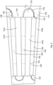
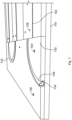
- Figs. 6 and 7 show an embodiment of an installation having a plurality of tube engagement units according to this invention.
- the tube engagement units 100 are supported via the blocks 114a, 114b, 114c, 114d, where the tube engagement units 100 and the blocks 114a, 114b, 114c, 114d alternate in a rectilinearly parallel manner, although other configurations are possible, as disclosed herein.
- the tube engagement units 100 and the blocks 114a, 114b, 114c, 114d are positioned between a plurality of blocks 130, such as a plurality of sleepers.
- the blocks 130 define a plurality of bores 138 bored therethrough, such as for fastening to the subfloor 118.
- the bores 138 are circular, but other shapes are possible, such as ovoid, elliptical, or others.
- the bores 138 are smooth, but may be threaded.
- the bores 138 are identical in shape and size, but can differ in shape, size, or any other characteristic, including positioning.
- the bores 138 host a plurality of fasteners 140, such as screws, bolts, nails, or others, whether identical to or different from each other in structure, function, or positioning.
- the fasteners 140 fasten the blocks 130 to the subfloor 118.
- the bores 110 host a plurality of fasteners 128, such as screws, bolts, nails, or others, whether identical to or different from each other in structure, function, or positioning.
- the fasteners 128 fasten the tube engagement units 100 to the blocks 114a, 114b, 114c, 114d.
- the blocks 130 define a plurality of U-shaped trenches 132 and a plurality of arcuate trenches 136.
- Each of the U-shaped trenches 132 includes a first open end portion and a second open end portion.
- Each of the arcuate trenches 136 includes a first open end portion and a second open end portion. As fully assembled, the first pen end portions and the second open end portions of the U-shaped trenches 132 and the arcuate trenches 136 are aligned with the channels 108.
- the tube 112 is routed in a serpentine manner via the tube engagement units 100, as supported via the blocks 114a, 114b, 114c, 114d, and via the U-shaped trenches 132 and via the arcuate trenches 136. Note that a plurality of portions 134 of the tube 112 in the U-shaped trenches 132 and in the arcuate trenches 136 are exposed.
- FIG. 8 shows an embodiment of a U-shaped cover according to this invention.
- FIG. 9 shows an embodiment of a U-shaped cover covering a U-shaped trench such that a tube is positioned therebetween according to this invention.
- a U-shaped cover 142 structured to cover the U-shaped trench 132 such that the tube 112 extends between the U-shaped trench 132 and the U-shaped cover 142.
- the U-shaped cover 142 may be unsecured to the block 130 or adjacent blocks 114 or secured to the block 130 or adjacent blocks 114.
- such securing can be via fastening, mating, adhering, magnetizing, nailing, or other securing techniques.
- the U-shaped cover 142 includes a thermally conductive material, such as metal, such as copper, iron, aluminum, or others, or an alloy, such as steel, brass, bronze, or others.
- the U-shaped plate 142 is solid, but can be perforated.
- the U-shaped plate 142 is planar and flat, but variations are possible, such as via depressions or projections.
- the U-shaped cover 142 can include a bore or can include a magnetic area.
- the U-shaped cover 142 extends longitudinally as a rectangular strip, but variations are possible, such as trapezoidal or others.
- the arcuate trench 136 is covered with an arcuate cover, which may be similar to the U-shaped cover 142, as disclosed herein, such as when the arcuate trench 136 does not return back towards the block 114d and runs rectilinearly along the block 130 or away from the block 130, such as to form an S-shape.
- the plate 102 and the U-shaped cover 142 shield the tube 112 from puncture, such as from nails or sharp objects, or external pressure, such as a dropped heavy object or a worker foot, or others undesired forces or objects.
- the plate 102 or the U-shaped cover 142 acts as a heat transfer plate while also providing a structural protection to prevent undesired forces, such as nails or screws, from penetrating into the tube 112 during flooring installation.
- the U-shaped cover 142 is coupled to the tube 112 using a compound, such as, for example, a heat sink compound.
- the heat sink compound is an adhesive, such as, for example, glue, paste, silicone, gel, epoxy, urethane, acrylate, or other adhesives.
- the compound includes a thermally conductive, metal oxide powder, such as, for example, aluminum oxide, boron nitride, zinc oxide, aluminum nitride, or other metal or metal oxide, metal boride or metal nitride powders.
- the heat sink compound is used to couple the tube engagement unit 100 to the tube 112 in place of or in addition to the legs 106.
- each of the blocks 130 includes sub-blocks 131, 133, and 135 positioned between the subfloor 118 and the finished floor 120.
- Each of the sub-blocks 131 have semi-circular and/or quarter circular cutouts.
- Each of the sub-blocks 133 are semi-circles, and each of the sub-blocks 135 are quarter circles.
- each of the sub-blocks includes a ledge and a wall defining the ledge.
- the sub-blocks 131, 133 and/or 135 have an angular cross-section on the curved edges, but other shapes are possible, whether symmetric or asymmetric, such as square, a rectangle, a triangle, an oval, a circle, or any other polygonal or non-polygonal shape.
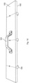
- FIG. 10 shows an embodiment of a block for supporting a tube engagement device according to this invention.
- FIG. 11 shows an embodiment of a block for supporting a tube engagement device according to this disclosure.
- a block 144 such as a sleeper, is elongated and T-shaped as defined via a pair of ledges 146, 150 extending from a stem as defined via a pair of walls 148, 152.
- the block 144 includes a thermally insulating material, such as wood, such as plywood.
- the block 144 is solid, but can be perforated.
- the block 144 can include a bore or can include a magnet.
- the block 144 is planar and flat, but variations are possible, such as via depressions or projections.
- Each of the ledges 146, 150 can support the plate 102.
- FIG. 12 shows an embodiment of a tube engagement unit being supported via a pair of blocks according to this invention.
- the tube engagement unit 100 is supported via a pair of the blocks 144 such that the tube engagement unit 100 is positioned therebetween.
- FIG. 13 shows an embodiment of a plurality of blocks supporting a plurality of tube engagement units according to this invention.
- the tube engagement units 100 are supported via the blocks 144 such that the tube engagement units 100 are alternately positioned therebetween.
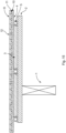
- FIG. 15 shows an embodiment of a first mode of installation 150 of underfloor hydronic tubing according to this invention.
- FIG. 16 shows an embodiment of a second mode of installation 160 of underfloor hydronic tubing according to this invention.
- FIG. 17 shows an embodiment of a third mode of installation 170 of underfloor hydronic tubing according to this invention.
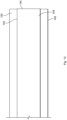
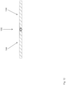
- Each of the first mode of installation 150, the second mode of installation 160, and the third mode of installation 170 is shown in cross-section, with each layer identified in a part list on respective Figs. 15-17 .
- FIG. 18 shows a jig for spacing apart a plurality of blocks according to this invention.
- a jig 180 includes an elongated block 182, a handle 184, and a plurality of legs 186.
- the handle 184 is secured to the block 182, such as via fastening, mating, magnetizing, adhering, or other securing techniques, whether removably or irremovably.
- the legs 186 are secured to the block 182 via fastening, but other securing techniques, such as mating, magnetizing, adhering, or others, can be used, whether removably or irremovably.
- At least one of the legs 186 is L-shaped as defined via a stem and a tail, with the block 182 facing the stem and the tail enveloping the block 182 such that the block 182 contacts the tail or against the tail.
- the legs 186 are spaced apart from each other and extend transversely to the block 182.
- the block 182 can include wood, plastic, metal, or other materials.
- the block 182 is shaped as a cuboid, but other shapes are possible, such as pyramid, trapezoidal prism, a cube, a hemisphere, or others.
- the block 182 is solid, but can be perforated.
- the block 182, on any surface, can be longitudinally marked with a graduated scale, such as a ruler, whether grooved thereon or written thereon in a visually or touch distinct manner.
- the handle 184 can include wood, plastic, metal, or other materials.
- the handle 184 is U-shaped, but can be shaped differently, such as an L-shape, a V-shape, or others. At least one of the legs 186 can include wood, plastic, metal, or other materials.
- the jig 180 can include a level, such as a bubble level or a spirit level, including a multi-liquid container level for various measurements.
- the level can be secured to or integrated with the block 182, the handle 184, or at least one of the legs 186.
- the jig 180 is used in a method for establishing a proper spacing of between blocks 114 the tube 112 and the tube engagement unit 100.
- the method includes positioning a first block 114a on a surface, such as the subfloor 118, where the first block 114a includes a first ledge 122a and a first wall 124a.
- the method includes positioning a first leg 186a of a segment, such as the block 182, on the first ledge 122a against the first wall 124a, where the segment includes a second leg 186b.
- the method includes positioning a second block 114b on the surface, where the second block 114b includes a second ledge 122b and a second wall 124b, where the first wall 124a faces the second wall 124b.
- the method includes positioning the second leg 186b on the second ledge 122b against the second wall 124b.
- the method includes securing the second block 114b to the surface. Therefore, the blocks 114a, 114b can be equally spaced.
Landscapes
- Engineering & Computer Science (AREA)
- Physics & Mathematics (AREA)
- Thermal Sciences (AREA)
- Chemical & Material Sciences (AREA)
- Combustion & Propulsion (AREA)
- Mechanical Engineering (AREA)
- General Engineering & Computer Science (AREA)
- Supports For Pipes And Cables (AREA)
- Steam Or Hot-Water Central Heating Systems (AREA)
Applications Claiming Priority (3)
| Application Number | Priority Date | Filing Date | Title |
|---|---|---|---|
| US201762485504P | 2017-04-14 | 2017-04-14 | |
| US15/727,008 US10006643B1 (en) | 2017-04-14 | 2017-10-06 | Technologies for underfloor fluid conduction |
| PCT/US2018/027501 WO2018191625A1 (en) | 2017-04-14 | 2018-04-13 | Technologies for underfloor fluid conduction |
Publications (3)
| Publication Number | Publication Date |
|---|---|
| EP3610090A1 EP3610090A1 (en) | 2020-02-19 |
| EP3610090A4 EP3610090A4 (en) | 2020-12-02 |
| EP3610090B1 true EP3610090B1 (en) | 2024-11-20 |
Family
ID=62623918
Family Applications (1)
| Application Number | Title | Priority Date | Filing Date |
|---|---|---|---|
| EP18785118.3A Active EP3610090B1 (en) | 2017-04-14 | 2018-04-13 | Technologies for underfloor fluid conduction |
Country Status (4)
| Country | Link |
|---|---|
| US (2) | US10006643B1 (da) |
| EP (1) | EP3610090B1 (da) |
| DK (1) | DK3610090T3 (da) |
| WO (1) | WO2018191625A1 (da) |
Family Cites Families (32)
| Publication number | Priority date | Publication date | Assignee | Title |
|---|---|---|---|---|
| US1800150A (en) * | 1927-01-29 | 1931-04-07 | Musgrave Joseph Leslie | Heating and cooling of buildings |
| CH430110A (de) | 1964-09-04 | 1967-02-15 | Stramax Ag | Strahlungseinrichtung mit an beheizten oder gekühlten Trägern befestigten Wärme- und Kälteverteilorganen |
| DE3411339A1 (de) * | 1984-03-28 | 1985-10-10 | geb. Weenen Gerda 5489 Kelberg Laroche | Plattenfoermiges bauteil mit eingeformten rillen zur wahlweisen aufnahme von rohrleitungen fuer fussbodenheizungen |
| US6152377A (en) | 1992-06-30 | 2000-11-28 | Fiedrich; Joachim | Radiant floor and wall hydronic heating system tubing attachment to radiant plate |
| US5454428A (en) | 1993-11-22 | 1995-10-03 | Radiant Engineering, Inc. | Hydronic radiant heat distribution panel and system |
| US5957378A (en) * | 1994-03-08 | 1999-09-28 | Fiedrich; Joachim | Radiant floor and wall hydronic heating systems |
| US5862854A (en) | 1995-01-27 | 1999-01-26 | Rhp Systems, Inc. | Radiant heating panel |
| EP0733866A3 (de) | 1995-03-21 | 1997-04-16 | Giacomini Services And Enginee | Heiz- und Kühldecke |
| US5743330A (en) | 1996-09-09 | 1998-04-28 | Radiant Technology, Inc. | Radiant heat transfer panels |
| US6009612A (en) | 1996-11-12 | 2000-01-04 | Fiedrich; Joachim | Apparatus for attaching radiating plate to holders of modular unit for radiant floor and wall hydronic heating systems |
| ES2192698T3 (es) * | 1996-12-05 | 2003-10-16 | Showa Denko Kk | Intercambiador de calor. |
| US6079182A (en) * | 1997-11-05 | 2000-06-27 | Ellenberger; Jack Richard | Floor panel compressing apparatus and method |
| US6283382B1 (en) | 2000-08-15 | 2001-09-04 | Michael Fitzemeyer | Radiant heating system pipe mounting plate |
| US20030155100A1 (en) * | 2002-02-21 | 2003-08-21 | William Montague | Baseboard heating apparatus |
| US20040040693A1 (en) | 2002-09-04 | 2004-03-04 | Joachim Fiedrich | In a dry installation of a radiant floor or wall hydronic heating system, metal radiating sheets that attach to the rough floor or wall adapted with a metal slot for holding hot water tubing |
| US20040074631A1 (en) | 2002-10-17 | 2004-04-22 | Jeon Chang Seong | Dry type heating pipeline structure and construction method thereof |
| EP1574788A1 (en) | 2002-12-19 | 2005-09-14 | Mitsubishi Chemical Functional Products, Inc. | Heat dissipating unit for floor heating system |
| KR100950714B1 (ko) * | 2003-05-29 | 2010-03-31 | 한라공조주식회사 | 열교환기용 플레이트 |
| US7559577B2 (en) * | 2007-03-16 | 2009-07-14 | Mando Corporation | Impact absorption steering apparatus |
| US20090101306A1 (en) | 2007-10-22 | 2009-04-23 | Reis Bradley E | Heat Exchanger System |
| US8176694B2 (en) * | 2008-02-29 | 2012-05-15 | Batori Imre | Heated floor support structure |
| US8288689B1 (en) * | 2008-09-02 | 2012-10-16 | Adelman Dean W | Radiant heating and cooling panel |
| DE102008055978A1 (de) | 2008-11-05 | 2010-05-06 | Brecht, Wido E. | Platten-Unterbau zum flächigen Verlegen von Rohrleitungen für Heiz- Kühl- oder Absorberzwecke, zum Beispiel für Fußboden- oder Wandheizungen sowie Verfahren zur Herstellung einer solchen Heizung |
| KR20130002812U (ko) | 2010-05-04 | 2013-05-09 | 그라프텍 인터내셔널 홀딩스 인코포레이티드 | 개량된 열 교환기 시스템 및 방법 |
| KR20110127872A (ko) * | 2010-05-20 | 2011-11-28 | 최영길 | 히트 파이프를 이용한 온수 난방장치 |
| CA2812198C (en) * | 2010-10-04 | 2019-12-31 | Dana Canada Corporation | Conformal fluid-cooled heat exchanger for battery |
| US10041250B2 (en) | 2011-06-30 | 2018-08-07 | Enrique Tarraga Sanchez | Modular panel for thermal energy transfer |
| CN202813569U (zh) | 2012-10-11 | 2013-03-20 | 周文 | 一种具有弧形固定槽的干式节能地暖多向导热板 |
| CN202813568U (zh) | 2012-10-11 | 2013-03-20 | 周文 | 一种具有y形固定槽的干式节能地暖多向导热板 |
| US9146038B2 (en) * | 2013-06-12 | 2015-09-29 | Codi Group, Llc | Impact and/or sound deadening hydronic sub-flooring panel and related system and method |
| KR101386923B1 (ko) | 2013-11-01 | 2014-04-18 | 이병철 | 층간소음방지 온수난방시스템 |
| CN205153456U (zh) | 2015-11-26 | 2016-04-13 | 浙江亚厦装饰股份有限公司 | 一种干铺式石材地暖安装结构 |
-
2017
- 2017-10-06 US US15/727,008 patent/US10006643B1/en active Active
-
2018
- 2018-04-13 DK DK18785118.3T patent/DK3610090T3/da active
- 2018-04-13 WO PCT/US2018/027501 patent/WO2018191625A1/en not_active Ceased
- 2018-04-13 EP EP18785118.3A patent/EP3610090B1/en active Active
- 2018-06-25 US US16/017,101 patent/US10928074B2/en active Active
Also Published As
| Publication number | Publication date |
|---|---|
| EP3610090A4 (en) | 2020-12-02 |
| US10928074B2 (en) | 2021-02-23 |
| US10006643B1 (en) | 2018-06-26 |
| WO2018191625A1 (en) | 2018-10-18 |
| EP3610090A1 (en) | 2020-02-19 |
| US20180306450A1 (en) | 2018-10-25 |
| DK3610090T3 (da) | 2024-12-09 |
Similar Documents
| Publication | Publication Date | Title |
|---|---|---|
| US5931381A (en) | For radiant floor, wall and ceiling hydronic heating and/or cooling systems using metal plates that are heated or cooled by attached tubing that is fed hot or cold water, techniques of improving performance and avoiding condensation when cooling | |
| CA2419486C (en) | Radiant heating system pipe mounting plate | |
| KR101569026B1 (ko) | 공동주택용 단열재 고정장치 | |
| CA2236560C (en) | Apparatus and method of attaching radiating plate to holders of modular unit for radiant floor and wall hydronic heating systems | |
| UA89912C2 (ru) | Краевые блоки панели для отопления комнаты и способ их укладки | |
| KR20140053163A (ko) | 열에너지 전달용 모듈형 패널 | |
| EP3610090B1 (en) | Technologies for underfloor fluid conduction | |
| US9404665B1 (en) | Radiant panel system having increased efficiency | |
| CN203821783U (zh) | 便于稳固安装的地暖地板 | |
| KR102053584B1 (ko) | 조립식 온수온돌용 열전도판 및 그 시공방법 | |
| CN216196263U (zh) | 一种保温装饰一体板的锚固结构 | |
| EP2989268B1 (en) | Method for attaching brick slips | |
| CN213449248U (zh) | 一种快装墙板安装结构 | |
| KR20170119130A (ko) | 기능성 패널형 바닥재 및 그 패널형 바닥재를 이용한 건식 난방 시공 방법 | |
| WO2008136571A1 (en) | Assembly unit for electric heating apparatus | |
| JP2014201877A (ja) | 金具付きタイル及び金具付きタイルを用いた壁構造 | |
| CN116950342A (zh) | 一种板材安装结构及其安装方法 | |
| DK2813766T3 (da) | Varmevekslerpanelsystem | |
| EP0943873A1 (en) | Apparatus and method of attaching radiating plate to holders of modular unit for radiant floor and wall hydronic heating systems | |
| KR101188312B1 (ko) | 진공단열재를 이용한 단열시공방법 및 이의 구조 | |
| CN210659055U (zh) | 保温隔热贴片石及安装组件 | |
| CN223907705U (zh) | 装配式内装墙体系统 | |
| CN206346465U (zh) | 一种复合瓷砖定位打孔装置 | |
| KR200188093Y1 (ko) | 난방용 온돌패널 | |
| KR200384608Y1 (ko) | 온수 방열판 |
Legal Events
| Date | Code | Title | Description |
|---|---|---|---|
| STAA | Information on the status of an ep patent application or granted ep patent |
Free format text: STATUS: THE INTERNATIONAL PUBLICATION HAS BEEN MADE |
|
| PUAI | Public reference made under article 153(3) epc to a published international application that has entered the european phase |
Free format text: ORIGINAL CODE: 0009012 |
|
| STAA | Information on the status of an ep patent application or granted ep patent |
Free format text: STATUS: REQUEST FOR EXAMINATION WAS MADE |
|
| 17P | Request for examination filed |
Effective date: 20191031 |
|
| AK | Designated contracting states |
Kind code of ref document: A1 Designated state(s): AL AT BE BG CH CY CZ DE DK EE ES FI FR GB GR HR HU IE IS IT LI LT LU LV MC MK MT NL NO PL PT RO RS SE SI SK SM TR |
|
| AX | Request for extension of the european patent |
Extension state: BA ME |
|
| DAV | Request for validation of the european patent (deleted) | ||
| DAX | Request for extension of the european patent (deleted) | ||
| A4 | Supplementary search report drawn up and despatched |
Effective date: 20201103 |
|
| RIC1 | Information provided on ipc code assigned before grant |
Ipc: F24D 3/14 20060101ALI20201028BHEP Ipc: E04F 15/04 20060101ALI20201028BHEP Ipc: F16L 5/00 20060101ALI20201028BHEP Ipc: E04B 5/48 20060101AFI20201028BHEP |
|
| STAA | Information on the status of an ep patent application or granted ep patent |
Free format text: STATUS: EXAMINATION IS IN PROGRESS |
|
| 17Q | First examination report despatched |
Effective date: 20230124 |
|
| GRAP | Despatch of communication of intention to grant a patent |
Free format text: ORIGINAL CODE: EPIDOSNIGR1 |
|
| STAA | Information on the status of an ep patent application or granted ep patent |
Free format text: STATUS: GRANT OF PATENT IS INTENDED |
|
| INTG | Intention to grant announced |
Effective date: 20240621 |
|
| GRAS | Grant fee paid |
Free format text: ORIGINAL CODE: EPIDOSNIGR3 |
|
| GRAA | (expected) grant |
Free format text: ORIGINAL CODE: 0009210 |
|
| STAA | Information on the status of an ep patent application or granted ep patent |
Free format text: STATUS: THE PATENT HAS BEEN GRANTED |
|
| AK | Designated contracting states |
Kind code of ref document: B1 Designated state(s): AL AT BE BG CH CY CZ DE DK EE ES FI FR GB GR HR HU IE IS IT LI LT LU LV MC MK MT NL NO PL PT RO RS SE SI SK SM TR |
|
| REG | Reference to a national code |
Ref country code: GB Ref legal event code: FG4D |
|
| REG | Reference to a national code |
Ref country code: CH Ref legal event code: EP |
|
| REG | Reference to a national code |
Ref country code: DE Ref legal event code: R096 Ref document number: 602018076752 Country of ref document: DE |
|
| REG | Reference to a national code |
Ref country code: DK Ref legal event code: T3 Effective date: 20241205 |
|
| REG | Reference to a national code |
Ref country code: NL Ref legal event code: FP Ref country code: IE Ref legal event code: FG4D |
|
| REG | Reference to a national code |
Ref country code: SE Ref legal event code: TRGR |
|
| P01 | Opt-out of the competence of the unified patent court (upc) registered |
Free format text: CASE NUMBER: APP_67082/2024 Effective date: 20241218 |
|
| REG | Reference to a national code |
Ref country code: LT Ref legal event code: MG9D |
|
| PG25 | Lapsed in a contracting state [announced via postgrant information from national office to epo] |
Ref country code: HR Free format text: LAPSE BECAUSE OF FAILURE TO SUBMIT A TRANSLATION OF THE DESCRIPTION OR TO PAY THE FEE WITHIN THE PRESCRIBED TIME-LIMIT Effective date: 20241120 Ref country code: IS Free format text: LAPSE BECAUSE OF FAILURE TO SUBMIT A TRANSLATION OF THE DESCRIPTION OR TO PAY THE FEE WITHIN THE PRESCRIBED TIME-LIMIT Effective date: 20250320 Ref country code: PT Free format text: LAPSE BECAUSE OF FAILURE TO SUBMIT A TRANSLATION OF THE DESCRIPTION OR TO PAY THE FEE WITHIN THE PRESCRIBED TIME-LIMIT Effective date: 20250320 |
|
| PG25 | Lapsed in a contracting state [announced via postgrant information from national office to epo] |
Ref country code: FI Free format text: LAPSE BECAUSE OF FAILURE TO SUBMIT A TRANSLATION OF THE DESCRIPTION OR TO PAY THE FEE WITHIN THE PRESCRIBED TIME-LIMIT Effective date: 20241120 |
|
| REG | Reference to a national code |
Ref country code: AT Ref legal event code: MK05 Ref document number: 1743692 Country of ref document: AT Kind code of ref document: T Effective date: 20241120 |
|
| PG25 | Lapsed in a contracting state [announced via postgrant information from national office to epo] |
Ref country code: BG Free format text: LAPSE BECAUSE OF FAILURE TO SUBMIT A TRANSLATION OF THE DESCRIPTION OR TO PAY THE FEE WITHIN THE PRESCRIBED TIME-LIMIT Effective date: 20241120 |
|
| PG25 | Lapsed in a contracting state [announced via postgrant information from national office to epo] |
Ref country code: ES Free format text: LAPSE BECAUSE OF FAILURE TO SUBMIT A TRANSLATION OF THE DESCRIPTION OR TO PAY THE FEE WITHIN THE PRESCRIBED TIME-LIMIT Effective date: 20241120 |
|
| PG25 | Lapsed in a contracting state [announced via postgrant information from national office to epo] |
Ref country code: GR Free format text: LAPSE BECAUSE OF FAILURE TO SUBMIT A TRANSLATION OF THE DESCRIPTION OR TO PAY THE FEE WITHIN THE PRESCRIBED TIME-LIMIT Effective date: 20250221 Ref country code: LV Free format text: LAPSE BECAUSE OF FAILURE TO SUBMIT A TRANSLATION OF THE DESCRIPTION OR TO PAY THE FEE WITHIN THE PRESCRIBED TIME-LIMIT Effective date: 20241120 Ref country code: AT Free format text: LAPSE BECAUSE OF FAILURE TO SUBMIT A TRANSLATION OF THE DESCRIPTION OR TO PAY THE FEE WITHIN THE PRESCRIBED TIME-LIMIT Effective date: 20241120 |
|
| PG25 | Lapsed in a contracting state [announced via postgrant information from national office to epo] |
Ref country code: PL Free format text: LAPSE BECAUSE OF FAILURE TO SUBMIT A TRANSLATION OF THE DESCRIPTION OR TO PAY THE FEE WITHIN THE PRESCRIBED TIME-LIMIT Effective date: 20241120 |
|
| PG25 | Lapsed in a contracting state [announced via postgrant information from national office to epo] |
Ref country code: RS Free format text: LAPSE BECAUSE OF FAILURE TO SUBMIT A TRANSLATION OF THE DESCRIPTION OR TO PAY THE FEE WITHIN THE PRESCRIBED TIME-LIMIT Effective date: 20250220 |
|
| PG25 | Lapsed in a contracting state [announced via postgrant information from national office to epo] |
Ref country code: SM Free format text: LAPSE BECAUSE OF FAILURE TO SUBMIT A TRANSLATION OF THE DESCRIPTION OR TO PAY THE FEE WITHIN THE PRESCRIBED TIME-LIMIT Effective date: 20241120 |
|
| PGFP | Annual fee paid to national office [announced via postgrant information from national office to epo] |
Ref country code: DE Payment date: 20250218 Year of fee payment: 8 |
|
| PGFP | Annual fee paid to national office [announced via postgrant information from national office to epo] |
Ref country code: DK Payment date: 20250411 Year of fee payment: 8 |
|
| PGFP | Annual fee paid to national office [announced via postgrant information from national office to epo] |
Ref country code: NO Payment date: 20250409 Year of fee payment: 8 |
|
| PG25 | Lapsed in a contracting state [announced via postgrant information from national office to epo] |
Ref country code: EE Free format text: LAPSE BECAUSE OF FAILURE TO SUBMIT A TRANSLATION OF THE DESCRIPTION OR TO PAY THE FEE WITHIN THE PRESCRIBED TIME-LIMIT Effective date: 20241120 |
|
| PG25 | Lapsed in a contracting state [announced via postgrant information from national office to epo] |
Ref country code: RO Free format text: LAPSE BECAUSE OF FAILURE TO SUBMIT A TRANSLATION OF THE DESCRIPTION OR TO PAY THE FEE WITHIN THE PRESCRIBED TIME-LIMIT Effective date: 20241120 |
|
| PG25 | Lapsed in a contracting state [announced via postgrant information from national office to epo] |
Ref country code: SK Free format text: LAPSE BECAUSE OF FAILURE TO SUBMIT A TRANSLATION OF THE DESCRIPTION OR TO PAY THE FEE WITHIN THE PRESCRIBED TIME-LIMIT Effective date: 20241120 |
|
| PG25 | Lapsed in a contracting state [announced via postgrant information from national office to epo] |
Ref country code: CZ Free format text: LAPSE BECAUSE OF FAILURE TO SUBMIT A TRANSLATION OF THE DESCRIPTION OR TO PAY THE FEE WITHIN THE PRESCRIBED TIME-LIMIT Effective date: 20241120 |
|
| REG | Reference to a national code |
Ref country code: DE Ref legal event code: R097 Ref document number: 602018076752 Country of ref document: DE |
|
| PLBE | No opposition filed within time limit |
Free format text: ORIGINAL CODE: 0009261 |
|
| STAA | Information on the status of an ep patent application or granted ep patent |
Free format text: STATUS: NO OPPOSITION FILED WITHIN TIME LIMIT |
|
| 26N | No opposition filed |
Effective date: 20250821 |
|
| REG | Reference to a national code |
Ref country code: CH Ref legal event code: H13 Free format text: ST27 STATUS EVENT CODE: U-0-0-H10-H13 (AS PROVIDED BY THE NATIONAL OFFICE) Effective date: 20251125 |
|
| PG25 | Lapsed in a contracting state [announced via postgrant information from national office to epo] |
Ref country code: LU Free format text: LAPSE BECAUSE OF NON-PAYMENT OF DUE FEES Effective date: 20250413 |
|
| PG25 | Lapsed in a contracting state [announced via postgrant information from national office to epo] |
Ref country code: MC Free format text: LAPSE BECAUSE OF FAILURE TO SUBMIT A TRANSLATION OF THE DESCRIPTION OR TO PAY THE FEE WITHIN THE PRESCRIBED TIME-LIMIT Effective date: 20241120 |
|
| REG | Reference to a national code |
Ref country code: BE Ref legal event code: MM Effective date: 20250430 |
|
| PG25 | Lapsed in a contracting state [announced via postgrant information from national office to epo] |
Ref country code: BE Free format text: LAPSE BECAUSE OF NON-PAYMENT OF DUE FEES Effective date: 20250430 |
|
| PG25 | Lapsed in a contracting state [announced via postgrant information from national office to epo] |
Ref country code: CH Free format text: LAPSE BECAUSE OF NON-PAYMENT OF DUE FEES Effective date: 20250430 |
|
| PGFP | Annual fee paid to national office [announced via postgrant information from national office to epo] |
Ref country code: NL Payment date: 20260227 Year of fee payment: 9 |
|
| PGFP | Annual fee paid to national office [announced via postgrant information from national office to epo] |
Ref country code: SE Payment date: 20260227 Year of fee payment: 9 |
|
| PGFP | Annual fee paid to national office [announced via postgrant information from national office to epo] |
Ref country code: GB Payment date: 20260223 Year of fee payment: 9 |
|
| PGFP | Annual fee paid to national office [announced via postgrant information from national office to epo] |
Ref country code: IE Payment date: 20260224 Year of fee payment: 9 |
|
| PGFP | Annual fee paid to national office [announced via postgrant information from national office to epo] |
Ref country code: IT Payment date: 20260320 Year of fee payment: 9 |
|
| PGFP | Annual fee paid to national office [announced via postgrant information from national office to epo] |
Ref country code: FR Payment date: 20260223 Year of fee payment: 9 |