EP3610103B1 - Clé et système comportant une clé et une serrure cylindrique - Google Patents
Clé et système comportant une clé et une serrure cylindrique Download PDFInfo
- Publication number
- EP3610103B1 EP3610103B1 EP18714251.8A EP18714251A EP3610103B1 EP 3610103 B1 EP3610103 B1 EP 3610103B1 EP 18714251 A EP18714251 A EP 18714251A EP 3610103 B1 EP3610103 B1 EP 3610103B1
- Authority
- EP
- European Patent Office
- Prior art keywords
- key
- extensions
- sensing
- cross
- encodings
- Prior art date
- Legal status (The legal status is an assumption and is not a legal conclusion. Google has not performed a legal analysis and makes no representation as to the accuracy of the status listed.)
- Active
Links
Images




Classifications
-
- E—FIXED CONSTRUCTIONS
- E05—LOCKS; KEYS; WINDOW OR DOOR FITTINGS; SAFES
- E05B—LOCKS; ACCESSORIES THEREFOR; HANDCUFFS
- E05B19/00—Keys; Accessories therefor
- E05B19/0017—Key profiles
- E05B19/0023—Key profiles characterized by variation of the contact surface between the key and the tumbler pins or plates
-
- E—FIXED CONSTRUCTIONS
- E05—LOCKS; KEYS; WINDOW OR DOOR FITTINGS; SAFES
- E05B—LOCKS; ACCESSORIES THEREFOR; HANDCUFFS
- E05B27/00—Cylinder locks or other locks with tumbler pins or balls that are set by pushing the key in
-
- E—FIXED CONSTRUCTIONS
- E05—LOCKS; KEYS; WINDOW OR DOOR FITTINGS; SAFES
- E05B—LOCKS; ACCESSORIES THEREFOR; HANDCUFFS
- E05B27/00—Cylinder locks or other locks with tumbler pins or balls that are set by pushing the key in
- E05B27/0003—Details
- E05B27/0017—Tumblers or pins
Definitions
- the invention relates to a key for a cylinder lock and a system comprising such a key and a cylinder lock.
- the cylinder lock comprises a housing with spring-loaded housing pins and a cylinder core rotatably mounted in the housing with a key channel and core pins protruding into the key channel, wherein the core pins have scanning extensions at their ends protruding into the key channel for querying codes of the key.
- Such cylinder locks are known.
- the codes on the key are usually formed by the depth of cut millings.
- AT 506 955 B1 such a cylinder lock as well as a flat key designed for it with cut millings on both the front surface and the side surface of the key, and correspondingly designed core pins.
- Conventional keys and conventional cylinder locks are DE 9 409 290 U1 , the BE 460 924 A , the EN 10 2015 008 016 A1 , the DE 92 11 896 U1 , the DE 94 03 191 U1 and the WO 2010/017941 A1 known.
- the DE 9 409 290 U1 discloses a key according to the preamble of claim 1. From the above-mentioned EN 10 2015 008 016 A1 Keys are known, whereby the width of the notch milling allows conclusions to be drawn about the depth of the notch milling.
- the codes are usually formed by milled cuts, the depth of which is directly proportional to the recess formed on the surface of the key.
- the recess formed on the surface can be easily measured, for example by high-resolution photography, so that the depth of the milled cut and thus the code of the key can be quickly determined.
- the object of the present invention is in particular to eliminate these and other problems of conventional keys and cylinder locks and to realize a key and a cylinder lock which, on the one hand, offers codings with sufficient variation possibilities and, on the other hand, makes rapid copying by photographing the codings more difficult.
- a key according to the invention has codings of different depths that taper from a surface of the key in the direction of a longitudinal axis of the key.
- taper means that the cross section of the coding, which is implemented as a hole or milled recess, for example, reduces in the direction of the longitudinal axis of the key, i.e. normal to the longitudinal extension of the key.
- the longitudinal axis of the key in this context is the axis that runs parallel to the key channel of the cylinder lock when a key is inserted into a cylinder lock.
- the surface mentioned can be a front surface, a side surface, or any other surface of the key, for example a groove base formed by a groove.
- At least two codes are provided, the extent of which on the surface of the key is essentially the same and which differ in their depth and in the rise of their taper in the direction of the longitudinal axis of the key. This ensures that the key interacts with any core pins of the associated cylinder lock, although the extent of the code on the surface of the key cannot be used to determine its slope and depth.
- the codes can, for example, be designed as holes so that the extent on the surface is essentially circular, or as cut millings so that the extent on the surface of the key is essentially rectangular. Other types of coding can also be provided according to the invention.
- the key is designed as a flat key, with the codings being provided on at least one front face of the flat key. According to the invention, it can also be provided that the key is designed as a flat key, with the codings being provided on at least one side face of the flat key. Combinations of these are also provided according to the invention, so that codings according to the invention are provided on both the front face and the side face of the key.
- the said surface of the key can be flat, curved, arched, convex, concave or of any shape.
- the surfaces can be arranged at right angles, but it can also be provided that the surfaces enclose any angle.
- the codings on the surface of the key are connected by a groove that runs continuously parallel to the longitudinal axis of the key without forming edges.
- the groove also has the advantage that the cut millings in the groove are laterally concealed by two ribs of remaining key material, which makes it even more difficult to copy the key.
- the codings are designed as essentially conical holes, the cross sections of which essentially form isosceles triangles, wherein at least two conical holes are provided, the cross sections of which essentially define isosceles triangles with different base angles. For example, base angles of 45°, 35° and 20°.
- the cross-sections of the codings can also form essentially isosceles trapezoids.
- the codings are designed as elongated incision millings, the cross sections of which essentially form circular arc sections, with at least two incision millings being provided, the cross sections of which essentially define circular arc sections with different radii of curvature.
- the incision millings can of course also have a different curved shape, for example the shape of an elliptical section.
- the cut-outs are arranged parallel to the longitudinal axis of the key, with at least two cut-outs being arranged at different normal distances from the longitudinal axis of the key. This provides a further possibility for varying the coding. In addition, to increase the variation options, it can also be provided that the cut-outs have different widths, i.e. different extensions normal to the longitudinal axis of the key.
- a key according to the invention can in principle be used with a conventional cylinder lock, since conventional scanning elements of a cylinder lock are able to query the depth of the key's coding.
- the invention also extends to a system with a key according to the invention and a cylinder lock.
- Such a cylinder lock comprises, in a known manner, a housing with spring-loaded housing pins and a cylinder core rotatably mounted in the housing with a key channel and core pins projecting into the key channel, which have scanning extensions on their ends projecting into the key channel for querying the coding of a key.
- the scanning extensions taper in the direction of the key channel, with at least two core pins being provided which have the same extension, in particular the same diameter, but whose scanning extensions differ in the increase of their taper.
- taper means that the cross section of the core pins tapers in the direction of the key channel, i.e. perpendicular to the Alignment of the keyway, reduced.
- the extent of the taper of the scanning extensions cannot be determined from the extent of the key's coding on the surface.
- the codings on the key have the same extent on the surface of the key, but differ in their depth and the extent of their taper.
- the core pins can have a circular cross-section with an identical diameter in a known manner.
- the scanning extensions of the core pins can be designed in the shape of a cone-pyramid starting from the core pins. However, embodiments of the invention with scanning extensions of any shape are also provided, for example scanning extensions that protrude into the key channel in an elliptical or circular segment-shaped manner starting from the core pins.
- the cross section of the scanning extensions forms a substantially isosceles triangle, wherein at least two core pins are provided, the scanning extensions of which define isosceles triangles with different base angles in cross section. For example, base angles of 45°, 35° and 20° can be provided.
- the cross section of the scanning extensions can also form a substantially isosceles trapezoid.
- the cross section of the scanning extensions essentially forms a circular arc section, wherein at least two core pins are provided, the scanning extensions of which have circular arc sections with different radii of curvature in cross section.
- the scanning extensions can of course also have another curved shape, for example the shape of an elliptical section.
- the different base angles or radii of curvature define the variations of the cylinder lock coding available at this scanning position.
- the scanning extensions are designed as elongated webs at the tip of the core pins and are aligned in the longitudinal direction of the key channel essentially parallel to a central longitudinal plane of the key channel. This allows coding in the form of cut millings on the surface of a key to be interrogated.
- At least two core pins have scanning extensions that run essentially parallel to one another and have a different distance from the central longitudinal plane of the key channel. This allows the number of variations of the lock to be increased further, since not only can different depths of cut milling be scanned, but also different normal distances from the central longitudinal plane are possible.
- the scanning extensions are designed to scan cuts on the front face of a flat key and that spring-loaded scanning pins with scanning cams projecting into the key channel are provided on at least one side of the keyway, which are designed to scan further codes on the side surfaces of the flat key, wherein the distance of the scanning cams from the central longitudinal plane of the key channel is greater than the distance of the scanning extensions from the central longitudinal plane.
- different types of core pins are provided that scan codes on the front faces and on the side faces of the key. This results in a particularly high number of variations in the possible codes.
- the scanning extensions are arranged at different normal distances from the central longitudinal plane of the key channel.
- the scanning extensions have different widths, i.e. different extensions normal to the central longitudinal plane of the key channel.
- key-lock systems can be provided in which existing locks can be locked using a group of keys according to the invention.
- Existing cylinder locks for example, have sensing extensions that protrude into the key channel as isosceles triangles or trapezoids with a base angle of 30°. These sensing extensions can be locked using appropriately designed, conical codings on the key with a base angle of 30°.
- keys with codings that have a larger base angle, for example 40° also lock:
- the edges of the sensing extensions remain attached to the edge of the coding on the surface of the key, while the tip of the sensing extensions does not touch the key.
- three different base angles of 20°, 30° and 45° can be provided, whereby keys with a 45° code lock cylinder locks with 20°, 30° and 45° codes, while keys with a 30° code lock cylinder locks with 20° and 30° codes, and keys with a 20° code only lock cylinder locks with 20° codes.
- This principle allows the keys according to the invention to be used to build hierarchies on existing locking systems, so that, for example, the new keys lock all old cylinder locks, but only selected new cylinder locks.
- Fig.1 shows a first embodiment of a cylinder lock with an inserted flat key 14 (not part of the invention) in cross section.
- the cylinder lock comprises a housing 1 and a cylinder core 3 rotatably mounted therein with a key channel 4.
- the cylinder core 3 can be brought into a release position for operating the lock in a basically known manner by inserting an authorized flat key 14.
- Spring-loaded housing pins 2 are provided in the housing 1 at the scanning positions A, B, C, D and E, which are connected in a manner also known in principle to Core pins 5 in the cylinder core 3 interact.
- the flat key 14 is authorized to lock the lock, so that the core pins 5 and the housing pins 2 are displaced by codings on the end faces of the flat key 14 in such a way that a division plane 15 is formed and the cylinder core 3 can be rotated in the housing 1.
- the core pins 5 protrude into the key channel 4 and have scanning extensions 6 at their ends protruding into the key channel 4 for querying codings of the flat key 14.
- the scanning extensions 6 taper in the direction of the key channel 4.
- the core pins 5 are cylindrical and the scanning extensions 6 have a conical pyramid-shaped taper, with the tip of the pyramid protruding into the key channel 4.
- the tip of the pyramid is slightly flattened during production, resulting in a trapezoidal cross-section.
- the invention is not limited to this shape.
- Core pins 5 with differently shaped scanning extensions are provided: at positions A and D a pyramid shape with a higher pitch is provided, at positions B and E a flatter pyramid shape, and at position C an even flatter pyramid shape.
- the diameter of the cylindrical core pins is always essentially identical.
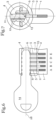
- Fig.2 shows the design of the cylinder lock from Fig.1 in cross-section, whereby the key is not shown in this illustration for reasons of better representation.
- spring-loaded housing pins 2 and core pins 5 are provided, whereby the core pins 5 have scanning extensions 6 at their ends projecting into the key channel 4.
- lateral scanning pins 12 with scanning cams 13 are provided to the left and right of the key channel 4, which are designed to scan codes (not shown) on the side surfaces of the flat key 14.
- the scanning cams 13, as well as the scanning extensions 6 of the core pins 5, project into the key channel 4.
- a central longitudinal plane 11 of the key channel 4 which runs in the middle of the key channel 4.
- Fig.3 shows various core pins of a cylinder lock that can be used as part of the invention in cross-section and in detailed representations.
- core pins 5, 5 ⁇ , 5" are provided, each with a different scanning extension 6, 6', 6".
- core pins 5 have identical scanning extensions 6 and only differ in their length.
- the core pins 5 at positions A, B and C are of different lengths despite the same scanning extension 6 in order to be able to query corresponding codings on a key.
- the diameter of the core pins 5, 5', 5" is always identical, however, and the core pins 5, 5', 5" are always essentially cylindrical at their end facing away from the key channel 4.
- the three different scanning extensions 6, 6', 6" are shown enlarged in the detailed representations.
- the scanning extensions 6, 6', 6" differ in the increase of their taper in the direction of the key channel 4, which is located at the top in the representation, despite having the same diameter.
- the scanning extensions 6, 6', 6" each form an isosceles triangle 7, 7', 7" with different base angles 8, 8', 8".
- base angles of approximately 45° are provided at scanning positions A, B and C, a base angle of approximately 35° at scanning position E, and a base angle of approximately 20° at scanning position D.
- the scanning extensions 6, 6', 6" can also have a trapezoidal cross section.
- Fig.4 shows an embodiment of a flat key 14 for operating a cylinder lock in cross section.
- the flat key 14 has on its front face 16 codings in the form of conical bores 17, 17', 17", which taper from a surface of the flat key 14, namely from the front face 16, in the direction of a longitudinal axis 18 of the flat key 14.
- the three different bores 17, 17', 17" are shown enlarged in the detailed illustrations.
- the bores 17, 17', 17" differ in the increase of their taper in the direction of the longitudinal axis 18 of the flat key 14, even though they have the same diameter on the surface of the key.
- the holes 17, 17', 17" each form an isosceles triangle 19, 19', 19" with different base angles 20, 20', 20".
- the tip is slightly flattened so that the cross-section resembles a trapezoid.
- base angles of approximately 45° are provided at scanning positions A and D, a base angle of approximately 35° at scanning positions B and E, and a base angle of approximately 20° at scanning position C.
- embodiments of the invention with other base angles are also provided.
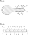
- Fig. 5a shows a side view of a flat key 14 according to the invention.
- the conical holes 17, 17', 17" are connected to a groove base 26 without the formation of significant edges by a groove 22 that runs continuously parallel to the longitudinal axis 18 on the front face 16 of the flat key 14.
- the groove 22 runs in such a way that the isosceles triangles 19, 19', 19" according to the invention are formed at the scanning positions A - E, but the transition to the surface of the key is as continuous as possible. This makes the coding even more difficult to recognize on a photograph of the front face 16 due to the lack of significant edges.
- Fig. 5b shows a view of a flat key 14 according to the invention from above.
- the conical holes 17, 17', 17" are indicated on the front surface 16, the extent of which in the form of a circular diameter on the surface of the flat key 14 is the same despite different depths and different increases in their taper. As a result, the coding cannot be deduced from a photograph of the surface.
- the holes 17, 17', 17" are connected to a groove base surface 26 by a continuous and edge-free groove 22 running essentially centrally along a longitudinal axis of the flat key 14, so that the depth of the holes 17, 17', 17" is even more difficult to recognize on a photograph of the surface of the flat key 14 due to the lack of clear edge formation.
- the edge of the holes 17, 17', 17" shown in the drawing is not visible in reality.
- codings in particular in the form of milled recesses, are also provided on the side surfaces 23.
- Fig.6 shows a further embodiment of a cylinder lock with an inserted flat key 14 not according to the invention in cross section.
- the cylinder lock comprises a housing 1 and a cylinder core 3 rotatably mounted therein with a key channel 4.
- the cylinder core 3 can be brought into a release position for operating the lock in a basically known manner by inserting an authorized flat key 14.
- Spring-loaded housing pins 2 are provided in the housing 1 at the scanning positions A, B, C, D and E, which interact in a manner that is also known in principle with core pins 5 in the cylinder core 3.
- the flat key 14 is authorized to lock the lock, so that the core pins 5 and the housing pins 2 are displaced by codings on the end faces of the flat key 14 in such a way that a division plane 15 is formed and the cylinder core 3 can be rotated in the housing 1.
- the core pins 5 protrude into the key channel 4 and have scanning extensions 6 at their ends protruding into the key channel 4 for querying codings of the flat key 14.
- the scanning extensions 6 taper in the direction of the key channel 4.
- the core pins 5 are essentially cylindrical and the scanning extensions 6 are web-shaped with a circular segment-shaped taper that protrudes into the key channel 4; however, the invention is not limited to this shape.
- the web-shaped scanning extensions are aligned essentially parallel to the central longitudinal plane 11 of the key channel 4.
- Core pins 5 with differently shaped scanning extensions are provided: at positions A, B and D a greater taper is provided, at position E a lesser taper, and at position C an even lesser taper.
- the diameter of the core pins is, however, always essentially identical.
- Fig.7 shows the example of the cylinder lock from Fig.6 in cross-section, whereby the key is not shown in this illustration for reasons of better representation.
- lateral scanning pins 12 with scanning cams 13 are provided to the left and right of the key channel 4, which are designed to scan codes (not shown) on the side surfaces 23 of the flat key 14.
- the scanning cams 13, as well as the scanning extensions 6 of the core pins 5, project into the key channel 4.
- Fig.8 shows various core pins of a cylinder lock that can be used as part of the invention in cross-section and in detailed representations.
- three differently designed core pins 5, 5', 5" are provided, each with different scanning extensions 6, 6', 6".
- core pins 5 have identical scanning extensions 6 and only differ in their length.
- the diameter of the core pins 5, 5', 5" is always identical, and the core pins 5, 5', 5" are always essentially cylindrical.
- the three different scanning extensions 6, 6', 6" differ in the increase of their taper in the direction of the key channel 4, which is located at the top in the illustration, despite having the same diameter.
- the scanning extensions 6, 6', 6" each essentially form a circular arc section 9, 9', 9" with different radii of curvature 10, 10', 10".
- the radius of curvature can, for example, be in the range of one to three times the diameter of the core pin 5.
- an elliptical section or another curved surface can also be provided.
- Fig.9 shows a further embodiment of a flat key 14 not according to the invention for operating a cylinder lock in cross section.
- the flat key 14 has on its front face 16 codings in the form of cut millings 21, 21', 21", which taper from a surface of the flat key 14, namely from the front face 16, in the direction of a longitudinal axis 18 of the flat key 14.
- the three different incision millings 21, 21', 21" are shown enlarged in the detailed representations.
- the incision millings 21, 21', 21" differ in the same dimension on the surface of the key in the increase of their taper in the direction of the longitudinal axis 18 of the flat key 14.
- the incision millings 21, 21', 21" each form a circular arc section 24, 24 ⁇ , 24" with a different radius of curvature 25, 25 ⁇ , 25".
- the radius of curvature can, for example, be in the range of one to three times the thickness of the flat key 14. Instead of a circular arc section, an elliptical section or another curved surface can also be provided.
- the incision millings 21, 21', 21" each have the identical extension x on the surface of the key, in this embodiment on the front face 16, so that the depth and curvature of the incision millings 21, 21', 21" cannot be determined from a photograph of the front face 16.
- Fig. 10a shows a side view of another flat key 14 according to the invention.
- the incision millings 21, 21', 21" are connected by a groove 22 that runs continuously parallel to the longitudinal axis 18 on the front face 16 of the flat key 14 without forming any significant edges.
- the groove 22 runs in such a way that the circular arc sections 24, 24 ⁇ , 24" according to the invention are formed at the scanning positions A - E, but the transition to the surface of the key is as continuous as possible. This makes the coding even more difficult to recognize on a photograph of the front face 16 due to the lack of any significant edges.
- the extent of the incision millings 21, 21', 21" is identical on the groove base surface 26. Additional codings can be provided on the front face 16, particularly on the sides.
- Fig. 10b shows a view of a flat key 14 according to the invention from above.
- the cut millings 21, 21', 21" are indicated on the front surface 16, the extent of which on the surface of the flat key 14 is always the same despite different depths and different increases in their taper. As a result, the coding cannot be deduced from a photograph of the surface.
- the incision millings 21, 21', 21" are connected to a groove base surface 26 running along the groove base by a continuous and edge-free groove 22 running essentially centrally along a longitudinal axis of the flat key 14, so that on a photograph of the surface of the flat key 14, the depth of the incision millings 21, 21', 21" compared to the groove base surface 26 is even more difficult to recognize due to the lack of clear edge formation.
- the edge of the incision millings 21, 21', 21" shown in the drawing is not visible in reality.
- the side surfaces 23 form an angle of substantially 90° with the end surfaces 16.
- the side surfaces 23 also form an angle of substantially 90° with the groove base surface 26. In embodiments of the invention not shown, however, these surfaces can also form other angles.
- codings in particular in the form of lateral cut millings, are also provided on the side surfaces 23 of the key 14.
Landscapes
- Lock And Its Accessories (AREA)
- Details Of Connecting Devices For Male And Female Coupling (AREA)
Claims (12)
- Clé pour une serrure à cylindre, caractérisée en ce que la clé présente des codages de profondeur différente qui se rétrécissent depuis une surface de la clé en direction d'un axe longitudinal (18) de la clé, au moins deux codages étant prévus, dont l'extension à la surface est substantiellement égale et qui se distinguent par leur profondeur et par la pente de leur rétrécissement en direction de l'axe longitudinal (18), caractérisé en ce que les codages sont reliés à la surface de la clé par une rainure (22) s'étendant en continu parallèlement à l'axe longitudinal (18) de la clé, sans formation d'arêtes.
- Clé selon la revendication 1, caractérisée en ce que la clé est réalisée sous forme de clé plate (14), les codages étant prévus sur au moins une face frontale (16) de la clé plate (14).
- Clé selon la revendication 1 ou 2, caractérisée en ce que la clé est réalisée sous forme de clé plate (14), les codages étant prévus sur au moins une face latérale (23) de la clé plate (14).
- Clé selon l'une des revendications 1 à 3, caractérisée en ce que les codages sont réalisés sous forme de trous (17, 17', 17") substantiellement coniques dont les sections transversales forment des triangles (19, 19', 19") substantiellement isocèles ou des trapèzes substantiellement isocèles, au moins deux trous (17, 17', 17") coniques étant prévus, dont les sections transversales définissent des triangles (19, 19', 19") substantiellement isocèles ou des trapèzes isocèles avec des angles de base (20, 20', 20") différents.
- Clé selon l'une des revendications 1 à 3, caractérisée en ce que les codages sont réalisés sous forme de fraisages d'entaille (21, 21', 21") allongés dont les sections transversales forment substantiellement des sections d'arc de cercle (24, 24', 24"), au moins deux fraisages d'entaille (21, 21', 21") étant prévus, dont les sections transversales définissent substantiellement des sections d'arc de cercle (24, 24', 24") avec un rayon de courbure (25, 25', 25") différent.
- Clé selon la revendication 5, caractérisée en ce que les fraisages d'entaille (21, 21', 21") sont disposés parallèlement à l'axe longitudinal (18) de la clé, au moins deux fraisages d'entaille (21, 21', 21") étant disposés à une distance normale différente de l'axe longitudinal (18) de la clé.
- Système composé d'une ou de plusieurs clés selon l'une des revendications 1 à 6 et d'une serrure à cylindre, caractérisé en ce que la serrure à cylindre comprend un boîtier (1) avec des tiges de boîtier (2) sollicitées par ressort et un noyau de cylindre (3) logé de manière rotative dans le boîtier (1) avec un canal de clé (4) et des tiges de noyau (5) pénétrant dans le canal de clé (4), les tiges de noyau (5) présentant à leurs extrémités pénétrant dans le canal de clé (4) des prolongements de balayage (6) pour l'interrogation de codages d'une clé, les prolongements de balayage (6) se rétrécissant en direction du canal de clé (4), au moins deux tiges de noyau (5, 5', 5") étant prévues, qui présentent la même extension, en particulier le même diamètre, mais dont les prolongements de balayage (6, 6', 6‴) se différencient dans la pente de leur rétrécissement.
- Système selon la revendication 7, caractérisé en ce que la section transversale des prolongements de balayage (6, 6', 6") forme un triangle (7, 7', 7") substantiellement isocèle ou un trapèze substantiellement isocèle, au moins deux tiges de noyau (5, 5', 5") étant prévues, dont les prolongements de balayage (6, 6', 6") définissent en section transversale des triangles (7, 7', 7") isocèles ou des trapèzes substantiellement isocèles avec des angles de base (8, 8', 8") différents.
- Système selon la revendication 7, caractérisé en ce que la section transversale des prolongements de balayage (6, 6', 6") forme substantiellement une section en arc de cercle, au moins deux tiges de noyau (5, 5', 5") étant prévues, dont les prolongements de balayage (6, 6', 6") présentent en section transversale des sections en arc de cercle (9, 9', 9") avec des rayons de courbure (10, 10', 10") différents.
- Système selon la revendication 9, caractérisé en ce que les prolongements de balayage (6, 6', 6") sont réalisés sous la forme de barrettes allongées à la pointe des tiges de noyau (5, 5', 5") et sont orientés dans la direction longitudinale du canal de clé (4) substantiellement parallèlement à un plan longitudinal médian (11) du canal de clé (4).
- Système selon la revendication 10, caractérisé en ce que au moins deux tiges de noyau (5, 5', 5") présentent des prolongements de balayage (6, 6', 6") s'étendant substantiellement parallèlement les uns aux autres, qui présentent une distance différente par rapport au plan longitudinal médian (11) du canal de clé (4).
- Système selon l'une des revendications 7 à 11, caractérisé en ce que les prolongements de balayage (6, 6', 6") sont réalisés pour balayer des fraisages d'entaille (21, 21', 21") sur la face frontale (16) d'une clé plate (14) et en ce que des tiges de balayage (12) précontraintes par ressort sont prévues sur au moins un côté du canal de clé (4) avec des cames de balayage (13) pénétrant dans le canal de clé (4), qui sont réalisées pour le balayage d'autres codages sur les faces latérales (23) de la clé plate (14), la distance des cames de balayage (13) par rapport au plan longitudinal médian (11) du canal de clé (4) étant supérieure à la distance des prolongements de balayage (6, 6', 6") par rapport au plan longitudinal médian (11).
Priority Applications (1)
| Application Number | Priority Date | Filing Date | Title |
|---|---|---|---|
| SM20240443T SMT202400443T1 (it) | 2017-04-11 | 2018-03-29 | Chiave e sistema con serratura a chiave e a cilindro |
Applications Claiming Priority (2)
| Application Number | Priority Date | Filing Date | Title |
|---|---|---|---|
| ATA50296/2017A AT519857B1 (de) | 2017-04-11 | 2017-04-11 | Schlüssel und Zylinderschloss |
| PCT/EP2018/058169 WO2018188971A1 (fr) | 2017-04-11 | 2018-03-29 | Clé et serrure cylindrique |
Publications (2)
| Publication Number | Publication Date |
|---|---|
| EP3610103A1 EP3610103A1 (fr) | 2020-02-19 |
| EP3610103B1 true EP3610103B1 (fr) | 2024-07-24 |
Family
ID=61827755
Family Applications (1)
| Application Number | Title | Priority Date | Filing Date |
|---|---|---|---|
| EP18714251.8A Active EP3610103B1 (fr) | 2017-04-11 | 2018-03-29 | Clé et système comportant une clé et une serrure cylindrique |
Country Status (7)
| Country | Link |
|---|---|
| EP (1) | EP3610103B1 (fr) |
| AT (1) | AT519857B1 (fr) |
| ES (1) | ES2992529T3 (fr) |
| PL (1) | PL3610103T3 (fr) |
| PT (1) | PT3610103T (fr) |
| SM (1) | SMT202400443T1 (fr) |
| WO (1) | WO2018188971A1 (fr) |
Families Citing this family (3)
| Publication number | Priority date | Publication date | Assignee | Title |
|---|---|---|---|---|
| DE102019201994A1 (de) * | 2019-02-14 | 2020-08-20 | Aug. Winkhaus Gmbh & Co. Kg | SCHLÜSSEL FÜR EINEN SCHLIEßZYLINDER |
| DE102019201997A1 (de) * | 2019-02-14 | 2020-08-20 | Aug. Winkhaus Gmbh & Co. Kg | SCHLIEßEINRICHTUNG MIT EINEM SCHLÜSSEL UND EINEM SCHLIEßZYLINDER |
| DE102019201995A1 (de) * | 2019-02-14 | 2020-08-20 | Aug. Winkhaus Gmbh & Co. Kg | SCHLÜSSEL FÜR EINEN SCHLIEßZYLINDER |
Family Cites Families (6)
| Publication number | Priority date | Publication date | Assignee | Title |
|---|---|---|---|---|
| BE460924A (fr) * | 1945-10-25 | 1945-11-30 | ||
| DE9211896U1 (de) * | 1992-08-27 | 1993-02-04 | Golub, Danijel, 7500 Karlsruhe | Zylinderschloß |
| DE9403191U1 (de) * | 1994-02-25 | 1994-09-29 | Golub, Danijel, 76185 Karlsruhe | Zylinderschloß und Schlüssel mit Grundlagen der Schließtechnik |
| DE9409290U1 (de) * | 1994-06-08 | 1994-09-22 | Knauer, Helga, 91054 Erlangen | Zuhaltestiftsystem zur Erweiterung der Schließvariationsmöglichkeiten |
| AT506955B1 (de) * | 2008-08-12 | 2010-01-15 | Evva Werke | Zylinderschloss mit zylindergehäuse und flachschlüssel für ein zylinderschloss |
| DE102015008016A1 (de) * | 2015-05-29 | 2016-12-01 | Iseo Deutschland Gmbh | Schlüssel, insbesondere Wendeschlüssel für ein Zylinderschloss-Schließsystem |
-
2017
- 2017-04-11 AT ATA50296/2017A patent/AT519857B1/de active
-
2018
- 2018-03-29 WO PCT/EP2018/058169 patent/WO2018188971A1/fr not_active Ceased
- 2018-03-29 EP EP18714251.8A patent/EP3610103B1/fr active Active
- 2018-03-29 SM SM20240443T patent/SMT202400443T1/it unknown
- 2018-03-29 PL PL18714251.8T patent/PL3610103T3/pl unknown
- 2018-03-29 PT PT187142518T patent/PT3610103T/pt unknown
- 2018-03-29 ES ES18714251T patent/ES2992529T3/es active Active
Also Published As
| Publication number | Publication date |
|---|---|
| PL3610103T3 (pl) | 2025-02-03 |
| EP3610103A1 (fr) | 2020-02-19 |
| ES2992529T3 (es) | 2024-12-13 |
| WO2018188971A1 (fr) | 2018-10-18 |
| AT519857B1 (de) | 2021-04-15 |
| SMT202400443T1 (it) | 2024-11-15 |
| PT3610103T (pt) | 2024-10-25 |
| AT519857A1 (de) | 2018-10-15 |
Similar Documents
| Publication | Publication Date | Title |
|---|---|---|
| EP0335069B1 (fr) | Clef plate pour serrures cylindriques ainsi que sa serrure cylindrique | |
| DD210722A5 (de) | Zylinderschloss mit zylindergehaeuse und einem zylinderkern sowie schluessel | |
| CH647837A5 (de) | Zylinderschloss, schluessel fuer das schloss und verfahren zur herstellung des schluessels. | |
| DE1553315A1 (de) | Drehzylinderschloss | |
| DE8035193U1 (de) | Schluessel fuer einen schliesszylinder | |
| EP3610103B1 (fr) | Clé et système comportant une clé et une serrure cylindrique | |
| EP1816288B1 (fr) | Serrure cylindrique et clé plate | |
| EP3814590B1 (fr) | Clé plate pour serrure cylindrique et serrure cylindrique | |
| EP4047161B1 (fr) | Clés, clés et barillets | |
| EP3191663B1 (fr) | Clé | |
| EP2890856A1 (fr) | Ébauche, clé de sécurité, système de verrouillage et procédé de fabrication | |
| EP1712714B1 (fr) | Combinaison d'une clé plate et d'une serrure cylindrique | |
| EP3526429B1 (fr) | Clé, serrure et système de fermeture | |
| DE2700350A1 (de) | Aufbruchsichere schliessvorrichtung | |
| DE2135106B2 (de) | Zylinderkern für ein zylinderschloss | |
| EP4253699A1 (fr) | Clé pour un cylindre de fermeture et cylindre de fermeture pour une telle clé | |
| EP1726749A2 (fr) | Serrure cylindrique et clé | |
| EP1746226B1 (fr) | Clé | |
| AT503166B1 (de) | Zylinderschloss sowie flachschlüssel | |
| EP1437462B1 (fr) | Système de clé et serrure de sécurité | |
| EP2149657B1 (fr) | Clé pour un cylindre de serrure et ébauche pour une telle clé | |
| AT385076B (de) | Schluessel, sowie zylinderschloss mit zylindergehaeuse und einem zylinderkern | |
| AT372472B (de) | Zylinderschloss und schluessel, schluessel fuer das zylinderschloss und verfahren zur herstellung des schluessels | |
| EP3412849B1 (fr) | Clé pour un cylindre de fermeture et cylindre de fermeture pour une telle clé | |
| EP2078807B1 (fr) | Clé pour une serrure cylindrique |
Legal Events
| Date | Code | Title | Description |
|---|---|---|---|
| STAA | Information on the status of an ep patent application or granted ep patent |
Free format text: STATUS: UNKNOWN |
|
| STAA | Information on the status of an ep patent application or granted ep patent |
Free format text: STATUS: THE INTERNATIONAL PUBLICATION HAS BEEN MADE |
|
| PUAI | Public reference made under article 153(3) epc to a published international application that has entered the european phase |
Free format text: ORIGINAL CODE: 0009012 |
|
| STAA | Information on the status of an ep patent application or granted ep patent |
Free format text: STATUS: REQUEST FOR EXAMINATION WAS MADE |
|
| 17P | Request for examination filed |
Effective date: 20190916 |
|
| AK | Designated contracting states |
Kind code of ref document: A1 Designated state(s): AL AT BE BG CH CY CZ DE DK EE ES FI FR GB GR HR HU IE IS IT LI LT LU LV MC MK MT NL NO PL PT RO RS SE SI SK SM TR |
|
| AX | Request for extension of the european patent |
Extension state: BA ME |
|
| DAV | Request for validation of the european patent (deleted) | ||
| DAX | Request for extension of the european patent (deleted) | ||
| P01 | Opt-out of the competence of the unified patent court (upc) registered |
Effective date: 20230509 |
|
| STAA | Information on the status of an ep patent application or granted ep patent |
Free format text: STATUS: EXAMINATION IS IN PROGRESS |
|
| 17Q | First examination report despatched |
Effective date: 20230707 |
|
| GRAP | Despatch of communication of intention to grant a patent |
Free format text: ORIGINAL CODE: EPIDOSNIGR1 |
|
| STAA | Information on the status of an ep patent application or granted ep patent |
Free format text: STATUS: GRANT OF PATENT IS INTENDED |
|
| INTG | Intention to grant announced |
Effective date: 20240216 |
|
| GRAS | Grant fee paid |
Free format text: ORIGINAL CODE: EPIDOSNIGR3 |
|
| GRAA | (expected) grant |
Free format text: ORIGINAL CODE: 0009210 |
|
| STAA | Information on the status of an ep patent application or granted ep patent |
Free format text: STATUS: THE PATENT HAS BEEN GRANTED |
|
| RIN1 | Information on inventor provided before grant (corrected) |
Inventor name: BAUMHAUER, WALTER |
|
| AK | Designated contracting states |
Kind code of ref document: B1 Designated state(s): AL AT BE BG CH CY CZ DE DK EE ES FI FR GB GR HR HU IE IS IT LI LT LU LV MC MK MT NL NO PL PT RO RS SE SI SK SM TR |
|
| REG | Reference to a national code |
Ref country code: GB Ref legal event code: FG4D Free format text: NOT ENGLISH |
|
| REG | Reference to a national code |
Ref country code: CH Ref legal event code: EP |
|
| REG | Reference to a national code |
Ref country code: IE Ref legal event code: FG4D Free format text: LANGUAGE OF EP DOCUMENT: GERMAN Ref country code: DE Ref legal event code: R096 Ref document number: 502018014894 Country of ref document: DE |
|
| REG | Reference to a national code |
Ref country code: NL Ref legal event code: FP |
|
| REG | Reference to a national code |
Ref country code: PT Ref legal event code: SC4A Ref document number: 3610103 Country of ref document: PT Date of ref document: 20241025 Kind code of ref document: T Free format text: AVAILABILITY OF NATIONAL TRANSLATION Effective date: 20241021 |
|
| REG | Reference to a national code |
Ref country code: SE Ref legal event code: TRGR |
|
| REG | Reference to a national code |
Ref country code: LT Ref legal event code: MG9D |
|
| REG | Reference to a national code |
Ref country code: GR Ref legal event code: EP Ref document number: 20240402446 Country of ref document: GR Effective date: 20241111 |
|
| REG | Reference to a national code |
Ref country code: ES Ref legal event code: FG2A Ref document number: 2992529 Country of ref document: ES Kind code of ref document: T3 Effective date: 20241213 |
|
| REG | Reference to a national code |
Ref country code: SK Ref legal event code: T3 Ref document number: E 45187 Country of ref document: SK |
|
| PG25 | Lapsed in a contracting state [announced via postgrant information from national office to epo] |
Ref country code: FI Free format text: LAPSE BECAUSE OF FAILURE TO SUBMIT A TRANSLATION OF THE DESCRIPTION OR TO PAY THE FEE WITHIN THE PRESCRIBED TIME-LIMIT Effective date: 20240724 |
|
| PG25 | Lapsed in a contracting state [announced via postgrant information from national office to epo] |
Ref country code: BG Free format text: LAPSE BECAUSE OF FAILURE TO SUBMIT A TRANSLATION OF THE DESCRIPTION OR TO PAY THE FEE WITHIN THE PRESCRIBED TIME-LIMIT Effective date: 20240724 |
|
| PG25 | Lapsed in a contracting state [announced via postgrant information from national office to epo] |
Ref country code: LV Free format text: LAPSE BECAUSE OF FAILURE TO SUBMIT A TRANSLATION OF THE DESCRIPTION OR TO PAY THE FEE WITHIN THE PRESCRIBED TIME-LIMIT Effective date: 20240724 |
|
| PG25 | Lapsed in a contracting state [announced via postgrant information from national office to epo] |
Ref country code: IS Free format text: LAPSE BECAUSE OF FAILURE TO SUBMIT A TRANSLATION OF THE DESCRIPTION OR TO PAY THE FEE WITHIN THE PRESCRIBED TIME-LIMIT Effective date: 20241124 |
|
| PG25 | Lapsed in a contracting state [announced via postgrant information from national office to epo] |
Ref country code: HR Free format text: LAPSE BECAUSE OF FAILURE TO SUBMIT A TRANSLATION OF THE DESCRIPTION OR TO PAY THE FEE WITHIN THE PRESCRIBED TIME-LIMIT Effective date: 20240724 |
|
| PG25 | Lapsed in a contracting state [announced via postgrant information from national office to epo] |
Ref country code: LV Free format text: LAPSE BECAUSE OF FAILURE TO SUBMIT A TRANSLATION OF THE DESCRIPTION OR TO PAY THE FEE WITHIN THE PRESCRIBED TIME-LIMIT Effective date: 20240724 Ref country code: IS Free format text: LAPSE BECAUSE OF FAILURE TO SUBMIT A TRANSLATION OF THE DESCRIPTION OR TO PAY THE FEE WITHIN THE PRESCRIBED TIME-LIMIT Effective date: 20241124 Ref country code: HR Free format text: LAPSE BECAUSE OF FAILURE TO SUBMIT A TRANSLATION OF THE DESCRIPTION OR TO PAY THE FEE WITHIN THE PRESCRIBED TIME-LIMIT Effective date: 20240724 Ref country code: FI Free format text: LAPSE BECAUSE OF FAILURE TO SUBMIT A TRANSLATION OF THE DESCRIPTION OR TO PAY THE FEE WITHIN THE PRESCRIBED TIME-LIMIT Effective date: 20240724 Ref country code: BG Free format text: LAPSE BECAUSE OF FAILURE TO SUBMIT A TRANSLATION OF THE DESCRIPTION OR TO PAY THE FEE WITHIN THE PRESCRIBED TIME-LIMIT Effective date: 20240724 |
|
| PG25 | Lapsed in a contracting state [announced via postgrant information from national office to epo] |
Ref country code: DK Free format text: LAPSE BECAUSE OF FAILURE TO SUBMIT A TRANSLATION OF THE DESCRIPTION OR TO PAY THE FEE WITHIN THE PRESCRIBED TIME-LIMIT Effective date: 20240724 Ref country code: RO Free format text: LAPSE BECAUSE OF FAILURE TO SUBMIT A TRANSLATION OF THE DESCRIPTION OR TO PAY THE FEE WITHIN THE PRESCRIBED TIME-LIMIT Effective date: 20240724 |
|
| PG25 | Lapsed in a contracting state [announced via postgrant information from national office to epo] |
Ref country code: EE Free format text: LAPSE BECAUSE OF FAILURE TO SUBMIT A TRANSLATION OF THE DESCRIPTION OR TO PAY THE FEE WITHIN THE PRESCRIBED TIME-LIMIT Effective date: 20240724 |
|
| REG | Reference to a national code |
Ref country code: DE Ref legal event code: R097 Ref document number: 502018014894 Country of ref document: DE |
|
| PLBE | No opposition filed within time limit |
Free format text: ORIGINAL CODE: 0009261 |
|
| STAA | Information on the status of an ep patent application or granted ep patent |
Free format text: STATUS: NO OPPOSITION FILED WITHIN TIME LIMIT |
|
| 26N | No opposition filed |
Effective date: 20250425 |
|
| PGFP | Annual fee paid to national office [announced via postgrant information from national office to epo] |
Ref country code: ES Payment date: 20250429 Year of fee payment: 8 |
|
| PGFP | Annual fee paid to national office [announced via postgrant information from national office to epo] |
Ref country code: CH Payment date: 20250401 Year of fee payment: 8 |
|
| REG | Reference to a national code |
Ref country code: CH Ref legal event code: U11 Free format text: ST27 STATUS EVENT CODE: U-0-0-U10-U11 (AS PROVIDED BY THE NATIONAL OFFICE) Effective date: 20260401 |
|
| PGFP | Annual fee paid to national office [announced via postgrant information from national office to epo] |
Ref country code: SM Payment date: 20260226 Year of fee payment: 9 |
|
| PGFP | Annual fee paid to national office [announced via postgrant information from national office to epo] |
Ref country code: SE Payment date: 20260319 Year of fee payment: 9 |
|
| PGFP | Annual fee paid to national office [announced via postgrant information from national office to epo] |
Ref country code: GB Payment date: 20260324 Year of fee payment: 9 |
|
| PGFP | Annual fee paid to national office [announced via postgrant information from national office to epo] |
Ref country code: MC Payment date: 20260323 Year of fee payment: 9 |
|
| PGFP | Annual fee paid to national office [announced via postgrant information from national office to epo] |
Ref country code: NO Payment date: 20260323 Year of fee payment: 9 Ref country code: DE Payment date: 20260304 Year of fee payment: 9 Ref country code: IE Payment date: 20260319 Year of fee payment: 9 |
|
| PGFP | Annual fee paid to national office [announced via postgrant information from national office to epo] |
Ref country code: AT Payment date: 20260302 Year of fee payment: 9 |
|
| PGFP | Annual fee paid to national office [announced via postgrant information from national office to epo] |
Ref country code: LU Payment date: 20260319 Year of fee payment: 9 Ref country code: BE Payment date: 20260319 Year of fee payment: 9 Ref country code: IT Payment date: 20260324 Year of fee payment: 9 |
|
| PGFP | Annual fee paid to national office [announced via postgrant information from national office to epo] |
Ref country code: NL Payment date: 20260319 Year of fee payment: 9 |
|
| PGFP | Annual fee paid to national office [announced via postgrant information from national office to epo] |
Ref country code: FR Payment date: 20260320 Year of fee payment: 9 |
|
| PGFP | Annual fee paid to national office [announced via postgrant information from national office to epo] |
Ref country code: CZ Payment date: 20260324 Year of fee payment: 9 Ref country code: PT Payment date: 20260319 Year of fee payment: 9 |
|
| PGFP | Annual fee paid to national office [announced via postgrant information from national office to epo] |
Ref country code: GR Payment date: 20260320 Year of fee payment: 9 Ref country code: PL Payment date: 20260219 Year of fee payment: 9 |
|
| PGFP | Annual fee paid to national office [announced via postgrant information from national office to epo] |
Ref country code: SK Payment date: 20260324 Year of fee payment: 9 |