EP3610103B1 - Schlüssel und system aus schlüssel und zylinderschloss - Google Patents
Schlüssel und system aus schlüssel und zylinderschloss Download PDFInfo
- Publication number
- EP3610103B1 EP3610103B1 EP18714251.8A EP18714251A EP3610103B1 EP 3610103 B1 EP3610103 B1 EP 3610103B1 EP 18714251 A EP18714251 A EP 18714251A EP 3610103 B1 EP3610103 B1 EP 3610103B1
- Authority
- EP
- European Patent Office
- Prior art keywords
- key
- extensions
- sensing
- cross
- encodings
- Prior art date
- Legal status (The legal status is an assumption and is not a legal conclusion. Google has not performed a legal analysis and makes no representation as to the accuracy of the status listed.)
- Active
Links
Images




Classifications
-
- E—FIXED CONSTRUCTIONS
- E05—LOCKS; KEYS; WINDOW OR DOOR FITTINGS; SAFES
- E05B—LOCKS; ACCESSORIES THEREFOR; HANDCUFFS
- E05B19/00—Keys; Accessories therefor
- E05B19/0017—Key profiles
- E05B19/0023—Key profiles characterized by variation of the contact surface between the key and the tumbler pins or plates
-
- E—FIXED CONSTRUCTIONS
- E05—LOCKS; KEYS; WINDOW OR DOOR FITTINGS; SAFES
- E05B—LOCKS; ACCESSORIES THEREFOR; HANDCUFFS
- E05B27/00—Cylinder locks or other locks with tumbler pins or balls that are set by pushing the key in
-
- E—FIXED CONSTRUCTIONS
- E05—LOCKS; KEYS; WINDOW OR DOOR FITTINGS; SAFES
- E05B—LOCKS; ACCESSORIES THEREFOR; HANDCUFFS
- E05B27/00—Cylinder locks or other locks with tumbler pins or balls that are set by pushing the key in
- E05B27/0003—Details
- E05B27/0017—Tumblers or pins
Definitions
- the invention relates to a key for a cylinder lock and a system comprising such a key and a cylinder lock.
- the cylinder lock comprises a housing with spring-loaded housing pins and a cylinder core rotatably mounted in the housing with a key channel and core pins protruding into the key channel, wherein the core pins have scanning extensions at their ends protruding into the key channel for querying codes of the key.
- Such cylinder locks are known.
- the codes on the key are usually formed by the depth of cut millings.
- AT 506 955 B1 such a cylinder lock as well as a flat key designed for it with cut millings on both the front surface and the side surface of the key, and correspondingly designed core pins.
- Conventional keys and conventional cylinder locks are DE 9 409 290 U1 , the BE 460 924 A , the EN 10 2015 008 016 A1 , the DE 92 11 896 U1 , the DE 94 03 191 U1 and the WO 2010/017941 A1 known.
- the DE 9 409 290 U1 discloses a key according to the preamble of claim 1. From the above-mentioned EN 10 2015 008 016 A1 Keys are known, whereby the width of the notch milling allows conclusions to be drawn about the depth of the notch milling.
- the codes are usually formed by milled cuts, the depth of which is directly proportional to the recess formed on the surface of the key.
- the recess formed on the surface can be easily measured, for example by high-resolution photography, so that the depth of the milled cut and thus the code of the key can be quickly determined.
- the object of the present invention is in particular to eliminate these and other problems of conventional keys and cylinder locks and to realize a key and a cylinder lock which, on the one hand, offers codings with sufficient variation possibilities and, on the other hand, makes rapid copying by photographing the codings more difficult.
- a key according to the invention has codings of different depths that taper from a surface of the key in the direction of a longitudinal axis of the key.
- taper means that the cross section of the coding, which is implemented as a hole or milled recess, for example, reduces in the direction of the longitudinal axis of the key, i.e. normal to the longitudinal extension of the key.
- the longitudinal axis of the key in this context is the axis that runs parallel to the key channel of the cylinder lock when a key is inserted into a cylinder lock.
- the surface mentioned can be a front surface, a side surface, or any other surface of the key, for example a groove base formed by a groove.
- At least two codes are provided, the extent of which on the surface of the key is essentially the same and which differ in their depth and in the rise of their taper in the direction of the longitudinal axis of the key. This ensures that the key interacts with any core pins of the associated cylinder lock, although the extent of the code on the surface of the key cannot be used to determine its slope and depth.
- the codes can, for example, be designed as holes so that the extent on the surface is essentially circular, or as cut millings so that the extent on the surface of the key is essentially rectangular. Other types of coding can also be provided according to the invention.
- the key is designed as a flat key, with the codings being provided on at least one front face of the flat key. According to the invention, it can also be provided that the key is designed as a flat key, with the codings being provided on at least one side face of the flat key. Combinations of these are also provided according to the invention, so that codings according to the invention are provided on both the front face and the side face of the key.
- the said surface of the key can be flat, curved, arched, convex, concave or of any shape.
- the surfaces can be arranged at right angles, but it can also be provided that the surfaces enclose any angle.
- the codings on the surface of the key are connected by a groove that runs continuously parallel to the longitudinal axis of the key without forming edges.
- the groove also has the advantage that the cut millings in the groove are laterally concealed by two ribs of remaining key material, which makes it even more difficult to copy the key.
- the codings are designed as essentially conical holes, the cross sections of which essentially form isosceles triangles, wherein at least two conical holes are provided, the cross sections of which essentially define isosceles triangles with different base angles. For example, base angles of 45°, 35° and 20°.
- the cross-sections of the codings can also form essentially isosceles trapezoids.
- the codings are designed as elongated incision millings, the cross sections of which essentially form circular arc sections, with at least two incision millings being provided, the cross sections of which essentially define circular arc sections with different radii of curvature.
- the incision millings can of course also have a different curved shape, for example the shape of an elliptical section.
- the cut-outs are arranged parallel to the longitudinal axis of the key, with at least two cut-outs being arranged at different normal distances from the longitudinal axis of the key. This provides a further possibility for varying the coding. In addition, to increase the variation options, it can also be provided that the cut-outs have different widths, i.e. different extensions normal to the longitudinal axis of the key.
- a key according to the invention can in principle be used with a conventional cylinder lock, since conventional scanning elements of a cylinder lock are able to query the depth of the key's coding.
- the invention also extends to a system with a key according to the invention and a cylinder lock.
- Such a cylinder lock comprises, in a known manner, a housing with spring-loaded housing pins and a cylinder core rotatably mounted in the housing with a key channel and core pins projecting into the key channel, which have scanning extensions on their ends projecting into the key channel for querying the coding of a key.
- the scanning extensions taper in the direction of the key channel, with at least two core pins being provided which have the same extension, in particular the same diameter, but whose scanning extensions differ in the increase of their taper.
- taper means that the cross section of the core pins tapers in the direction of the key channel, i.e. perpendicular to the Alignment of the keyway, reduced.
- the extent of the taper of the scanning extensions cannot be determined from the extent of the key's coding on the surface.
- the codings on the key have the same extent on the surface of the key, but differ in their depth and the extent of their taper.
- the core pins can have a circular cross-section with an identical diameter in a known manner.
- the scanning extensions of the core pins can be designed in the shape of a cone-pyramid starting from the core pins. However, embodiments of the invention with scanning extensions of any shape are also provided, for example scanning extensions that protrude into the key channel in an elliptical or circular segment-shaped manner starting from the core pins.
- the cross section of the scanning extensions forms a substantially isosceles triangle, wherein at least two core pins are provided, the scanning extensions of which define isosceles triangles with different base angles in cross section. For example, base angles of 45°, 35° and 20° can be provided.
- the cross section of the scanning extensions can also form a substantially isosceles trapezoid.
- the cross section of the scanning extensions essentially forms a circular arc section, wherein at least two core pins are provided, the scanning extensions of which have circular arc sections with different radii of curvature in cross section.
- the scanning extensions can of course also have another curved shape, for example the shape of an elliptical section.
- the different base angles or radii of curvature define the variations of the cylinder lock coding available at this scanning position.
- the scanning extensions are designed as elongated webs at the tip of the core pins and are aligned in the longitudinal direction of the key channel essentially parallel to a central longitudinal plane of the key channel. This allows coding in the form of cut millings on the surface of a key to be interrogated.
- At least two core pins have scanning extensions that run essentially parallel to one another and have a different distance from the central longitudinal plane of the key channel. This allows the number of variations of the lock to be increased further, since not only can different depths of cut milling be scanned, but also different normal distances from the central longitudinal plane are possible.
- the scanning extensions are designed to scan cuts on the front face of a flat key and that spring-loaded scanning pins with scanning cams projecting into the key channel are provided on at least one side of the keyway, which are designed to scan further codes on the side surfaces of the flat key, wherein the distance of the scanning cams from the central longitudinal plane of the key channel is greater than the distance of the scanning extensions from the central longitudinal plane.
- different types of core pins are provided that scan codes on the front faces and on the side faces of the key. This results in a particularly high number of variations in the possible codes.
- the scanning extensions are arranged at different normal distances from the central longitudinal plane of the key channel.
- the scanning extensions have different widths, i.e. different extensions normal to the central longitudinal plane of the key channel.
- key-lock systems can be provided in which existing locks can be locked using a group of keys according to the invention.
- Existing cylinder locks for example, have sensing extensions that protrude into the key channel as isosceles triangles or trapezoids with a base angle of 30°. These sensing extensions can be locked using appropriately designed, conical codings on the key with a base angle of 30°.
- keys with codings that have a larger base angle, for example 40° also lock:
- the edges of the sensing extensions remain attached to the edge of the coding on the surface of the key, while the tip of the sensing extensions does not touch the key.
- three different base angles of 20°, 30° and 45° can be provided, whereby keys with a 45° code lock cylinder locks with 20°, 30° and 45° codes, while keys with a 30° code lock cylinder locks with 20° and 30° codes, and keys with a 20° code only lock cylinder locks with 20° codes.
- This principle allows the keys according to the invention to be used to build hierarchies on existing locking systems, so that, for example, the new keys lock all old cylinder locks, but only selected new cylinder locks.
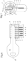
- Fig.1 shows a first embodiment of a cylinder lock with an inserted flat key 14 (not part of the invention) in cross section.
- the cylinder lock comprises a housing 1 and a cylinder core 3 rotatably mounted therein with a key channel 4.
- the cylinder core 3 can be brought into a release position for operating the lock in a basically known manner by inserting an authorized flat key 14.
- Spring-loaded housing pins 2 are provided in the housing 1 at the scanning positions A, B, C, D and E, which are connected in a manner also known in principle to Core pins 5 in the cylinder core 3 interact.
- the flat key 14 is authorized to lock the lock, so that the core pins 5 and the housing pins 2 are displaced by codings on the end faces of the flat key 14 in such a way that a division plane 15 is formed and the cylinder core 3 can be rotated in the housing 1.
- the core pins 5 protrude into the key channel 4 and have scanning extensions 6 at their ends protruding into the key channel 4 for querying codings of the flat key 14.
- the scanning extensions 6 taper in the direction of the key channel 4.
- the core pins 5 are cylindrical and the scanning extensions 6 have a conical pyramid-shaped taper, with the tip of the pyramid protruding into the key channel 4.
- the tip of the pyramid is slightly flattened during production, resulting in a trapezoidal cross-section.
- the invention is not limited to this shape.
- Core pins 5 with differently shaped scanning extensions are provided: at positions A and D a pyramid shape with a higher pitch is provided, at positions B and E a flatter pyramid shape, and at position C an even flatter pyramid shape.
- the diameter of the cylindrical core pins is always essentially identical.
- Fig.2 shows the design of the cylinder lock from Fig.1 in cross-section, whereby the key is not shown in this illustration for reasons of better representation.
- spring-loaded housing pins 2 and core pins 5 are provided, whereby the core pins 5 have scanning extensions 6 at their ends projecting into the key channel 4.
- lateral scanning pins 12 with scanning cams 13 are provided to the left and right of the key channel 4, which are designed to scan codes (not shown) on the side surfaces of the flat key 14.
- the scanning cams 13, as well as the scanning extensions 6 of the core pins 5, project into the key channel 4.
- a central longitudinal plane 11 of the key channel 4 which runs in the middle of the key channel 4.
- Fig.3 shows various core pins of a cylinder lock that can be used as part of the invention in cross-section and in detailed representations.
- core pins 5, 5 ⁇ , 5" are provided, each with a different scanning extension 6, 6', 6".
- core pins 5 have identical scanning extensions 6 and only differ in their length.
- the core pins 5 at positions A, B and C are of different lengths despite the same scanning extension 6 in order to be able to query corresponding codings on a key.
- the diameter of the core pins 5, 5', 5" is always identical, however, and the core pins 5, 5', 5" are always essentially cylindrical at their end facing away from the key channel 4.
- the three different scanning extensions 6, 6', 6" are shown enlarged in the detailed representations.
- the scanning extensions 6, 6', 6" differ in the increase of their taper in the direction of the key channel 4, which is located at the top in the representation, despite having the same diameter.
- the scanning extensions 6, 6', 6" each form an isosceles triangle 7, 7', 7" with different base angles 8, 8', 8".
- base angles of approximately 45° are provided at scanning positions A, B and C, a base angle of approximately 35° at scanning position E, and a base angle of approximately 20° at scanning position D.
- the scanning extensions 6, 6', 6" can also have a trapezoidal cross section.
- Fig.4 shows an embodiment of a flat key 14 for operating a cylinder lock in cross section.
- the flat key 14 has on its front face 16 codings in the form of conical bores 17, 17', 17", which taper from a surface of the flat key 14, namely from the front face 16, in the direction of a longitudinal axis 18 of the flat key 14.
- the three different bores 17, 17', 17" are shown enlarged in the detailed illustrations.
- the bores 17, 17', 17" differ in the increase of their taper in the direction of the longitudinal axis 18 of the flat key 14, even though they have the same diameter on the surface of the key.
- the holes 17, 17', 17" each form an isosceles triangle 19, 19', 19" with different base angles 20, 20', 20".
- the tip is slightly flattened so that the cross-section resembles a trapezoid.
- base angles of approximately 45° are provided at scanning positions A and D, a base angle of approximately 35° at scanning positions B and E, and a base angle of approximately 20° at scanning position C.
- embodiments of the invention with other base angles are also provided.
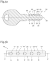
- Fig. 5a shows a side view of a flat key 14 according to the invention.
- the conical holes 17, 17', 17" are connected to a groove base 26 without the formation of significant edges by a groove 22 that runs continuously parallel to the longitudinal axis 18 on the front face 16 of the flat key 14.
- the groove 22 runs in such a way that the isosceles triangles 19, 19', 19" according to the invention are formed at the scanning positions A - E, but the transition to the surface of the key is as continuous as possible. This makes the coding even more difficult to recognize on a photograph of the front face 16 due to the lack of significant edges.
- Fig. 5b shows a view of a flat key 14 according to the invention from above.
- the conical holes 17, 17', 17" are indicated on the front surface 16, the extent of which in the form of a circular diameter on the surface of the flat key 14 is the same despite different depths and different increases in their taper. As a result, the coding cannot be deduced from a photograph of the surface.
- the holes 17, 17', 17" are connected to a groove base surface 26 by a continuous and edge-free groove 22 running essentially centrally along a longitudinal axis of the flat key 14, so that the depth of the holes 17, 17', 17" is even more difficult to recognize on a photograph of the surface of the flat key 14 due to the lack of clear edge formation.
- the edge of the holes 17, 17', 17" shown in the drawing is not visible in reality.
- codings in particular in the form of milled recesses, are also provided on the side surfaces 23.
- Fig.6 shows a further embodiment of a cylinder lock with an inserted flat key 14 not according to the invention in cross section.
- the cylinder lock comprises a housing 1 and a cylinder core 3 rotatably mounted therein with a key channel 4.
- the cylinder core 3 can be brought into a release position for operating the lock in a basically known manner by inserting an authorized flat key 14.
- Spring-loaded housing pins 2 are provided in the housing 1 at the scanning positions A, B, C, D and E, which interact in a manner that is also known in principle with core pins 5 in the cylinder core 3.
- the flat key 14 is authorized to lock the lock, so that the core pins 5 and the housing pins 2 are displaced by codings on the end faces of the flat key 14 in such a way that a division plane 15 is formed and the cylinder core 3 can be rotated in the housing 1.
- the core pins 5 protrude into the key channel 4 and have scanning extensions 6 at their ends protruding into the key channel 4 for querying codings of the flat key 14.
- the scanning extensions 6 taper in the direction of the key channel 4.
- the core pins 5 are essentially cylindrical and the scanning extensions 6 are web-shaped with a circular segment-shaped taper that protrudes into the key channel 4; however, the invention is not limited to this shape.
- the web-shaped scanning extensions are aligned essentially parallel to the central longitudinal plane 11 of the key channel 4.
- Core pins 5 with differently shaped scanning extensions are provided: at positions A, B and D a greater taper is provided, at position E a lesser taper, and at position C an even lesser taper.
- the diameter of the core pins is, however, always essentially identical.
- Fig.7 shows the example of the cylinder lock from Fig.6 in cross-section, whereby the key is not shown in this illustration for reasons of better representation.
- lateral scanning pins 12 with scanning cams 13 are provided to the left and right of the key channel 4, which are designed to scan codes (not shown) on the side surfaces 23 of the flat key 14.
- the scanning cams 13, as well as the scanning extensions 6 of the core pins 5, project into the key channel 4.
- Fig.8 shows various core pins of a cylinder lock that can be used as part of the invention in cross-section and in detailed representations.
- three differently designed core pins 5, 5', 5" are provided, each with different scanning extensions 6, 6', 6".
- core pins 5 have identical scanning extensions 6 and only differ in their length.
- the diameter of the core pins 5, 5', 5" is always identical, and the core pins 5, 5', 5" are always essentially cylindrical.
- the three different scanning extensions 6, 6', 6" differ in the increase of their taper in the direction of the key channel 4, which is located at the top in the illustration, despite having the same diameter.
- the scanning extensions 6, 6', 6" each essentially form a circular arc section 9, 9', 9" with different radii of curvature 10, 10', 10".
- the radius of curvature can, for example, be in the range of one to three times the diameter of the core pin 5.
- an elliptical section or another curved surface can also be provided.
- Fig.9 shows a further embodiment of a flat key 14 not according to the invention for operating a cylinder lock in cross section.
- the flat key 14 has on its front face 16 codings in the form of cut millings 21, 21', 21", which taper from a surface of the flat key 14, namely from the front face 16, in the direction of a longitudinal axis 18 of the flat key 14.
- the three different incision millings 21, 21', 21" are shown enlarged in the detailed representations.
- the incision millings 21, 21', 21" differ in the same dimension on the surface of the key in the increase of their taper in the direction of the longitudinal axis 18 of the flat key 14.
- the incision millings 21, 21', 21" each form a circular arc section 24, 24 ⁇ , 24" with a different radius of curvature 25, 25 ⁇ , 25".
- the radius of curvature can, for example, be in the range of one to three times the thickness of the flat key 14. Instead of a circular arc section, an elliptical section or another curved surface can also be provided.
- the incision millings 21, 21', 21" each have the identical extension x on the surface of the key, in this embodiment on the front face 16, so that the depth and curvature of the incision millings 21, 21', 21" cannot be determined from a photograph of the front face 16.
- Fig. 10a shows a side view of another flat key 14 according to the invention.
- the incision millings 21, 21', 21" are connected by a groove 22 that runs continuously parallel to the longitudinal axis 18 on the front face 16 of the flat key 14 without forming any significant edges.
- the groove 22 runs in such a way that the circular arc sections 24, 24 ⁇ , 24" according to the invention are formed at the scanning positions A - E, but the transition to the surface of the key is as continuous as possible. This makes the coding even more difficult to recognize on a photograph of the front face 16 due to the lack of any significant edges.
- the extent of the incision millings 21, 21', 21" is identical on the groove base surface 26. Additional codings can be provided on the front face 16, particularly on the sides.
- Fig. 10b shows a view of a flat key 14 according to the invention from above.
- the cut millings 21, 21', 21" are indicated on the front surface 16, the extent of which on the surface of the flat key 14 is always the same despite different depths and different increases in their taper. As a result, the coding cannot be deduced from a photograph of the surface.
- the incision millings 21, 21', 21" are connected to a groove base surface 26 running along the groove base by a continuous and edge-free groove 22 running essentially centrally along a longitudinal axis of the flat key 14, so that on a photograph of the surface of the flat key 14, the depth of the incision millings 21, 21', 21" compared to the groove base surface 26 is even more difficult to recognize due to the lack of clear edge formation.
- the edge of the incision millings 21, 21', 21" shown in the drawing is not visible in reality.
- the side surfaces 23 form an angle of substantially 90° with the end surfaces 16.
- the side surfaces 23 also form an angle of substantially 90° with the groove base surface 26. In embodiments of the invention not shown, however, these surfaces can also form other angles.
- codings in particular in the form of lateral cut millings, are also provided on the side surfaces 23 of the key 14.
Landscapes
- Lock And Its Accessories (AREA)
- Details Of Connecting Devices For Male And Female Coupling (AREA)
Description
- Die Erfindung betrifft einen Schlüssel für ein Zylinderschloss sowie ein System aus einem solchen Schlüssel und einem Zylinderschloss.
- Das Zylinderschloss umfasst ein Gehäuse mit federbelasteten Gehäusestiften und einen im Gehäuse drehbar gelagerten Zylinderkern mit einem Schlüsselkanal und in den Schlüsselkanal ragenden Kernstiften, wobei die Kernstifte an ihren in den Schlüsselkanal ragenden Enden Abtastfortsätze zur Abfrage von Codierungen des Schlüssels aufweisen.
- Derartige Zylinderschlösser sind bekannt. Insbesondere ist es bekannt, unterschiedliche Kernstifte vorzusehen und derart anzuordnen, dass einerseits Kernstifte zur Abfrage von Codierungen an der Stirnfläche eines Flachschlüssels, und andererseits Kernstifte zur Abfrage von Codierungen an der Seitenfläche eines derartigen Schlüssels vorgesehen sind. Die Codierungen am Schlüssel werden dabei regelmäßig durch die Tiefe von Einschnittfräsungen gebildet. Beispielsweise zeigt
AT 506 955 B1 - Herkömmliche Schlüssel und herkömmliche Zylinderschlösser sind beispielsweise aus der
DE 9 409 290 U1 , derBE 460 924 A DE 10 2015 008 016 A1 , derDE 92 11 896 U1 , derDE 94 03 191 U1 und derWO 2010/017941 A1 bekannt. DieDE 9 409 290 U1 offenbart dabei einen Schlüssel gemäß dem Oberbegriff des Anspruchs 1. Aus der oben angeführtenDE 10 2015 008 016 A1 sind Schlüssel bekannt, wobei die Breite der Einschnittfräsung Rückschlüsse auf die Tiefe der Einschnittfräsung zulässt. - Ein Problem derartiger Schlüssel und Zylinderschlösser besteht darin, dass sich nicht nur die Codierungen auf der Seitenfläche des Schlüssels, sondern auch die Codierungen auf der Stirnfläche des Schlüssels relativ einfach auslesen lassen. So sind bei den bekannten Schlüsseln die Codierungen meist durch Einschnittfräsungen gebildet, deren Tiefe fertigungstechnisch direkt proportional zu ihrer an der Oberfläche des Schlüssels gebildeten Ausnehmung ist. Die an der Oberfläche gebildete Ausnehmung lässt sich aber einfach, beispielsweise durch eine hochauflösende Fotografie, vermessen, sodass die Tiefe der Einschnittfräsung und damit die Codierung des Schlüssels schnell feststellbar ist.
- Die Aufgabe der vorliegenden Erfindung besteht insbesondere darin, diese und andere Probleme herkömmlicher Schlüssel und Zylinderschlösser zu beheben und einen Schlüssel sowie ein Zylinderschloss zu realisieren, der einerseits Codierungen mit ausreichend Variationsmöglichkeiten bietet, und andererseits ein schnelles Kopieren durch Fotografieren der Codierungen erschwert.
- Diese Aufgabe wird erfindungsgemäß durch einen Schlüssel gemäß Anspruch 1 und ein System aus einem oder mehreren erfindungsgemäßen Schlüsseln und einem Zylinderschloss gemäß Anspruch 7 gelöst.
- Ein erfindungsgemäßer Schlüssel weist unterschiedlich tiefe Codierungen auf, die sich von einer Oberfläche des Schlüssels in Richtung zu einer Längsachse des Schlüssels verjüngen. Verjüngung bedeutet in diesem Zusammenhang, dass sich der Querschnitt der Codierung, die beispielsweise als Bohrung oder Einschnittfräsung realisiert ist, in Richtung zur Längsachse des Schlüssels, also normal auf die Längserstreckung des Schlüssels, reduziert. Die Längsachse des Schlüssels ist in diesem Zusammenhang jene Achse, die bei einem, in ein Zylinderschloss eingesteckten Schlüssel parallel zum Schlüsselkanal des Zylinderschlosses verläuft. Bei der genannten Oberfläche kann es sich um eine Stirnfläche, eine Seitenfläche, oder eine beliebige andere Fläche des Schlüssels handeln, beispielsweise auch um eine durch eine Nut gebildete Nutengrundfläche.
- Erfindungsgemäß sind zumindest zwei Codierungen vorgesehen, deren Ausdehnung an der Oberfläche des Schlüssels im Wesentlichen gleich ist und die sich in ihrer Tiefe und im Anstieg ihrer Verjüngung in Richtung zur Längsachse des Schlüssels unterscheiden. Dadurch wird erreicht, dass der Schlüssel mit allfälligen Kernstiften des zugeordneten Zylinderschlosses zusammenwirkt, wobei jedoch aus der Ausdehnung der Codierung an der Oberfläche des Schlüssels nicht auf ihre Steigung und Tiefe geschlossen werden kann. Die Codierungen können beispielsweise als Bohrungen ausgeführt sein, sodass die Ausdehnung an der Oberfläche im Wesentlichen kreisförmig ist, oder auch als Einschnittfräsungen, sodass die Ausdehnung an der Oberfläche des Schlüssels im Wesentlichen rechteckförmig ist. Auch andere Arten der Codierung können erfindungsgemäß vorgesehen sein.
- Es kann vorgesehen sein, dass der Schlüssel als Flachschlüssel ausgeführt ist, wobei die Codierungen an zumindest einer Stirnfläche des Flachschlüssels vorgesehen sind. Erfindungsgemäß kann ebenfalls vorgesehen sein, dass der Schlüssel als Flachschlüssel ausgeführt ist, wobei die Codierungen an zumindest einer Seitenfläche des Flachschlüssels vorgesehen sind. Auch Kombinationen davon sind erfindungsgemäß vorgesehen, sodass sowohl an der Stirnfläche, als auch an der Seitenfläche des Schlüssels erfindungsgemäße Codierungen vorgesehen sind.
- Die genannte Oberfläche des Schlüssels, erfindungsgemäß die Nutengrundfläche einer Nut des Schlüssels, kann eben, gekrümmt, gewölbt, konvex, konkav oder in beliebiger Form ausgeführt sein. Die Flächen können rechtwinkelig angeordnet sein, es kann aber auch vorgesehen sein, dass die Flächen einen beliebigen Winkel einschließen.
- Erfindungsgemäß ist vorgesehen, dass die Codierungen an der Oberfläche des Schlüssels durch eine parallel zur Längsachse des Schlüssels stetig verlaufende Nut ohne Bildung von Kanten verbunden sind. Dadurch kann die Steigung und Tiefe der Codierungen effektiv verdeckt werden, sodass aus einer Ansicht oder Fotografie der Oberfläche des Schlüssels nicht auf die Tiefe und Steigung der Codierungen geschlossen werden kann. Für den Fall, dass die Codierungen an einer Stirnfläche eines Flachschlüssels vorgesehen sind, ergibt sich durch die Nut auch der Vorteil, dass die Einschnittfräsungen in der Nut durch zwei Rippen verbleibenden Schlüsselmaterials seitlich verdeckt werden, was die Nachmachbarkeit des Schlüssels noch weiter erschwert.
- Es kann vorgesehen sein, dass die Codierungen als im Wesentlichen kegelförmige Bohrungen ausgeführt sind, deren Querschnitte im Wesentlichen gleichschenkelige Dreiecke bilden, wobei zumindest zwei kegelförmige Bohrungen vorgesehen sind, deren Querschnitte im Wesentlichen gleichschenkelige Dreiecke mit unterschiedlichen Basiswinkeln definieren. Beispielsweise können Basiswinkel von 45°, 35° und 20° vorgesehen sein. Statt gleichschenkeliger Dreiecke können die Querschnitte der Codierungen auch im Wesentlichen gleichschenkelige Trapeze bilden.
- Es kann vorgesehen sein, dass die Codierungen als längliche Einschnittfräsungen ausgeführt sind, deren Querschnitte im Wesentlichen Kreisbogenabschnitte bilden, wobei zumindest zwei Einschnittfräsungen vorgesehen sind, deren Querschnitte im Wesentlichen Kreisbogenabschnitte mit unterschiedlichem Krümmungsradius definieren. Statt der Form eines Kreisbogens können die Einschnittfräsungen selbstverständlich auch eine andere gekrümmte Form aufweisen, beispielsweise die Form eines Ellipsenabschnitts.
- Es kann vorgesehen sein, dass die Einschnittfräsungen parallel zur Längsachse des Schlüssels angeordnet sind, wobei zumindest zwei Einschnittfräsungen in unterschiedlichem Normalabstand zur Längsachse des Schlüssels angeordnet sind. Dadurch ergibt sich eine weitere Möglichkeit zur Variation der Codierungen. Darüber hinaus kann zur Erhöhung der Variationsmöglichkeiten auch vorgesehen sein, dass die Einschnittfräsungen unterschiedliche Breite, also unterschiedliche Ausdehnung normal auf die Längsachse des Schlüssels, aufweisen.
- Ein erfindungsgemäßer Schlüssel kann grundsätzlich mit einem herkömmlichen Zylinderschloss eingesetzt werden, da herkömmliche Abtastelemente eines Zylinderschlosses in der Lage sind, die Tiefe der Codierungen des Schlüssels abzufragen. Die Erfindung erstreckt sich jedoch auch auf ein System mit einem erfindungsgemäßen Schlüssel und einem Zylinderschloss.
- Ein derartiges Zylinderschloss umfasst in bekannter Weise ein Gehäuse mit federbelasteten Gehäusestiften und einen im Gehäuse drehbar gelagerten Zylinderkern mit einem Schlüsselkanal und in den Schlüsselkanal ragenden Kernstiften, die an ihren in den Schlüsselkanal ragenden Enden Abtastfortsätze zur Abfrage der Codierungen eines Schlüssels tragen. Es ist vorgesehen, dass sich die Abtastfortsätze in Richtung zum Schlüsselkanal verjüngen, wobei zumindest zwei Kernstifte vorgesehen sind, die gleiche Ausdehnung, insbesondere gleichen Durchmesser aufweisen, deren Abtastfortsätze sich jedoch im Anstieg ihrer Verjüngung unterscheiden. Verjüngung bedeutet in diesem Zusammenhang, dass sich der Querschnitt der Kernstifte in Richtung zum Schlüsselkanal, also normal auf die Ausrichtung des Schlüsselkanals, reduziert.
- Dadurch wird erreicht, dass bei einer Ansicht oder Fotografie der Oberfläche eines zum Sperren dieses Zylinderschlosses ausgeführten Schlüssels das Ausmaß der Verjüngung der Abtastfortsätze nicht aus der Ausdehnung der Codierung des Schlüssels an der Oberfläche bestimmen lässt. Die Codierungen am Schlüssel weisen an der Oberfläche des Schlüssels die gleiche Ausdehnung auf, unterscheiden sich jedoch in ihrer Tiefe und im Ausmaß ihrer Verjüngung.
- Die Kernstifte können in bekannter Weise einen kreisförmigen Querschnitt mit identischem Durchmesser aufweisen. Die Abtastfortsätze der Kernstifte können, ausgehend von den Kernstiften, kegelpyramidenförmig ausgeführt sein. Es sind jedoch auch Ausführungen der Erfindung mit beliebig geformten Abtastfortsätzen vorgesehen, beispielsweise Abtastfortsätze die ausgehend von den Kernstiften elliptisch oder kreisabschnittförmig in den Schlüsselkanal ragen.
- Es kann vorgesehen sein, dass der Querschnitt der Abtastfortsätze ein im Wesentlichen gleichschenkeliges Dreieck bildet, wobei zumindest zwei Kernstifte vorgesehen sind, deren Abtastfortsätze im Querschnitt gleichschenkelige Dreiecke mit unterschiedlichen Basiswinkeln definieren. Beispielsweise können Basiswinkel von 45°, 35° und 20° vorgesehen sein. Statt eines gleichschenkeligen Dreiecks kann der Querschnitt der Abtastfortsätze auch ein im Wesentlichen gleichschenkeliges Trapez bilden.
- Es kann vorgesehen sein, dass der Querschnitt der Abtastfortsätze im Wesentlichen einen Kreisbogenabschnitt bildet, wobei zumindest zwei Kernstifte vorgesehen sind, deren Abtastfortsätze im Querschnitt Kreisbogenabschnitte mit unterschiedlichen Krümmungsradien aufweisen. Statt der Form eines Kreisbogens können die Abtastfortsätze selbstverständlich auch eine andere gekrümmte Form aufweisen, beispielsweise die Form eines Ellipsenabschnitts.
- Die unterschiedlichen Basiswinkel oder Krümmungsradien definieren die an dieser Abtastposition zur Verfügung stehenden Variationen der Codierung des Zylinderschlosses.
- Es kann vorgesehen sein, dass die Abtastfortsätze als längliche Stege an der Spitze der Kernstifte ausgeführt sind und in Längsrichtung des Schlüsselkanals im Wesentlichen parallel zu einer Mittellängsebene des Schlüsselkanals ausgerichtet sind. Dadurch können Codierungen in Form von Einschnittfräsungen auf der Oberfläche eines Schlüssels abgefragt werden.
- Es kann vorgesehen sein, dass zumindest zwei Kernstifte zueinander im Wesentlichen parallel verlaufende Abtastfortsätze aufweisen, die einen unterschiedlichen Abstand zur Mittellängsebene des Schlüsselkanals aufweisen. Dadurch kann die Variationszahl des Schlosses weiter erhöht werden, da nicht nur unterschiedlich tiefe Einschnittfräsungen abfragbar sind, sondern auch verschiedene Normalabstände zur Mittellängsebene möglich sind.
- Es kann insbesondere vorgesehen sein, dass die Abtastfortsätze zum Abtasten von Einschnittfräsungen an der Stirnfläche eines Flachschlüssels ausgeführt sind und an zumindest einer Seite des Schlüsselkanals federnd vorgespannte Abtaststifte mit in den Schlüsselkanal ragenden Abtastnocken vorgesehen sind, welche zum Abtasten von weiteren Codierungen an den Seitenflächen des Flachschlüssels ausgeführt sind, wobei der Abstand der Abtastnocken von der Mittellängsebene des Schlüsselkanals größer ist als der Abstand der Abtastfortsätze von der Mittellängsebene. In diesem Fall sind also unterschiedliche Arten von Kernstiften vorgesehen, die Codierungen an den Stirnflächen und an den Seitenflächen des Schlüssels abfragen. Dadurch ergibt sich eine besonders hohe Variationszahl der möglichen Codierungen.
- Weiters kann vorgesehen sein, dass die Abtastfortsätze in unterschiedlichem Normalabstand zur Mittellängsebene des Schlüsselkanals angeordnet sind. Darüber hinaus kann zur Erhöhung der Variationsmöglichkeiten auch vorgesehen sein, dass die Abtastfortsätze unterschiedliche Breite, also unterschiedliche Ausdehnung normal auf die Mittellängsebene des Schlüsselkanals, aufweisen.
- Ein besonderer Vorteil der erfindungsgemäße Schlüssel wird im Folgenden beschrieben. Da die Codierungen der Schlüssel an der Schlüsseloberfläche stets die gleiche Ausdehnung aufweisen, können Schlüssel-Schloss Systeme vorgesehen werden, bei denen bestehende Schlösser durch eine Gruppe erfindungsgemäßer Schlüssel gesperrt werden können. Bestehende Zylinderschlösser weisen beispielsweise Abtastfortsätze auf, die als gleichschenkelige Dreiecke oder Trapeze mit einem Basiswinkel von 30° in den Schlüsselkanal ragen. Diese Abtastfortsätze können durch entsprechend ausgeführte, kegelförmige Codierungen am Schlüssel mit einem Basiswinkel von 30° gesperrt werden. Da aber die Ausdehnung der Codierung an der Oberfläche des Schlüssels stets gleich ist, sperren auch Schlüssel mit Codierungen, die einen größeren Basiswinkel, beispielsweise 40°, aufweisen: Die Ränder der Abtastfortsätze bleiben in diesem Fall am Rand der Codierung an der Oberfläche des Schlüssels hängen, während die Spitze der Abtastfortsätze den Schlüssel nicht berührt. Konkret können drei unterschiedliche Basiswinkel 20°, 30°, 45° vorgesehen sein, wobei Schlüssel mit einer 45°-Codierung Zylinderschlösser mit 20°, 30° und 45°-Codierung sperren, während Schlüssel mit einer 30°-Codierung Zylinderschlösser mit 20° und 30°-Codierung sperren, und Schlüssel mit einer 20°-Codierung nur die Zylinderschlösser mit 20°-Codierung sperren. Durch dieses Prinzip lassen sich mit den erfindungsgemäßen Schlüsseln Hierarchien auf bestehende Schließanlagen aufbauen, sodass beispielsweise die neuen Schlüssel zwar alle alten Zylinderschlösser sperren, aber nur ausgewählte neue Zylinderschlösser.
- Weitere erfindungsgemäße Merkmale ergeben sich aus den Ansprüchen, der Beschreibung der Ausführungsbeispiele und den Zeichnungen.
- Im Folgenden wird die Erfindung an Hand einiger, in Figuren schematisch dargestellter Ausführungsbeispiele näher erläutert.
-
Fig. 1 zeigt ein Zylinderschloss mit einem eingesteckten erfindungsgemäßen Schlüssel im Querschnitt; -
Fig. 2 zeigt das Zylinderschloss ausFig. 1 im Querschnitt; -
Fig. 3 zeigt verschiedene Kernstifte eines Zylinderschlosses im Querschnitt und in Detaildarstellungen; -
Fig. 4 zeigt eine Ausführungsform eines nicht erfindungsgemäßen Schlüssels zur Betätigung eines Zylinderschlosses im Querschnitt; -
Fig. 5a-5b zeigen eine Ausführungsform eines erfindungsgemäßen Flachschlüssels im Querschnitt und in Draufsicht; -
Fig. 6 zeigt eine weitere Ausführungsform eines Zylinderschlosses mit einem eingesteckten nicht erfindungsgemäßen Schlüssel im Querschnitt; -
Fig. 7 zeigt die Ausführungsform des Zylinderschlosses ausFig. 6 im Querschnitt; -
Fig. 8 zeigt verschiedene Kernstifte eines Zylinderschlosses im Querschnitt und in Detaildarstellungen; -
Fig. 9 zeigt eine weitere Ausführungsform eines nicht erfindungsgemäßen Schlüssels zur Betätigung eines Zylinderschlosses im Querschnitt; -
Fig. 1 zeigt eine erste Ausführungsform eines Zylinderschlosses mit einem nicht zur Erfindung gehörenden eingesteckten Flachschlüssel 14 im Querschnitt. Das Zylinderschloss umfasst ein Gehäuse 1 und einen darin drehbar gelagerten Zylinderkern 3 mit einem Schlüsselkanal 4. Der Zylinderkern 3 ist in grundsätzlich bekannter Weise durch Einschieben eines berechtigten Flachschlüssels 14 in eine Freigabeposition zur Betätigung des Schlosses bringbar. - Im Gehäuse 1 sind an den Abtastpositionen A, B, C, D und E federbelastete Gehäusestifte 2 vorgesehen, die in grundsätzlich ebenfalls bekannter Weise mit Kernstiften 5 im Zylinderkern 3 zusammenwirken.
- In der dargestellten nicht erfindungsgemäßen Ausführungsform ist der Flachschlüssel 14 berechtigt, das Schloss zu sperren, sodass die Kernstifte 5 und die Gehäusestifte 2 durch Codierungen auf den Stirnflächen des Flachschlüssels 14 derart verschoben werden, dass sich eine Teilungsebene 15 bildet und der Zylinderkern 3 im Gehäuse 1 gedreht werden kann.
- Die Kernstifte 5 ragen in den Schlüsselkanal 4 und weisen an ihren, in den Schlüsselkanal 4 ragenden Enden Abtastfortsätze 6 zur Abfrage von Codierungen des Flachschlüssels 14 auf. Die Abtastfortsätze 6 verjüngen sich in Richtung zum Schlüsselkanal 4. Im konkreten Ausführungsbeispiel sind die Kernstifte 5 zylinderförmig, und die Abtastfortsätze 6 weisen eine kegelpyramidenförmige Verjüngung auf, wobei die Spitze der Pyramide in den Schlüsselkanal 4 ragt. Die Spitze der Pyramide ist fertigungstechnisch leicht abgeflacht, sodass sich ein trapezförmiger Querschnitt ergibt. Die Erfindung beschränkt sich jedoch nicht auf diese Form. Es sind Kernstifte 5 mit unterschiedlich geformten Abtastfortsätzen vorgesehen: an Position A und D ist eine Pyramidenform mit höherer Steigung vorgesehen, an Position B und E eine flachere Pyramidenform, und an Position C eine noch flachere Pyramidenform. Der Durchmesser der zylinderförmigen Kernstifte ist aber stets im Wesentlichen identisch.
-
Fig. 2 zeigt die Ausführungsform des Zylinderschlosses ausFig. 1 im Querschnitt, wobei in dieser Darstellung der Schlüssel aus Gründen der besseren Darstellbarkeit nicht dargestellt ist. Wiederum sind federbelastete Gehäusestifte 2 und Kernstifte 5 vorgesehen, wobei die Kernstifte 5 an ihren in den Schlüsselkanal 4 ragenden Enden Abtastfortsätze 6 aufweisen. Außerdem sind links und rechts vom Schlüsselkanal 4 seitliche Abtaststifte 12 mit Abtastnocken 13 vorgesehen, die zum Abtasten von nicht dargestellten Codierungen auf den Seitenflächen des Flachschlüssels 14 ausgeführt sind. Zu diesem Zweck ragen die Abtastnocken 13, wie auch die Abtastfortsätze 6 der Kernstifte 5, in den Schlüsselkanal 4. Ebenfalls dargestellt ist eine Mittellängsebene 11 des Schlüsselkanals 4, welche in der Mitte des Schlüsselkanals 4 verläuft. -
Fig. 3 zeigt verschiedene als Teil der Erfindung verwendbare Kernstifte eines Zylinderschlosses im Querschnitt und in Detaildarstellungen. - Im konkreten Ausführungsbeispiel sind drei unterschiedlich ausgeführte Kernstifte 5, 5`, 5" mit jeweils unterschiedlichen Abtastfortsätzen 6, 6', 6" vorgesehen. Es ist jedoch auch vorgesehen, dass Kernstifte 5 identische Abtastfortsätze 6 aufweisen und sich nur in ihrer Länge unterscheiden. So sind die Kernstifte 5 an Position A, B und C trotz gleichem Abtastfortsatz 6 unterschiedlich lang, um entsprechende Codierungen an einem Schlüssel abfragen zu können. Der Durchmesser der Kernstifte 5, 5', 5" ist jedoch stets identisch, und die Kernstifte 5, 5', 5" sind an ihrem, dem Schlüsselkanal 4 abgewandten Ende stets im Wesentlichen zylinderförmig.
- Die drei unterschiedlichen Abtastfortsätze 6, 6', 6" sind in den Detaildarstellungen vergrößert dargestellt. Die Abtastfortsätze 6, 6', 6" unterscheiden sich bei gleichem Durchmesser im Anstieg ihrer Verjüngung in Richtung zum Schlüsselkanal 4, der sich in der Darstellung oben befindet. Im dargestellten Querschnitt bilden die Abtastfortsätze 6, 6', 6" jeweils ein gleichschenkeliges Dreieck 7, 7', 7" mit unterschiedlichen Basiswinkeln 8, 8', 8". Im konkreten Ausführungsbeispiel sind an den Abtastpositionen A, B und C Basiswinkel von etwa 45°, an der Abtastposition E ein Basiswinkel von etwa 35°, und an der Abtastposition D ein Basiswinkel von etwa 20° vorgesehen. Es sind jedoch auch Ausführungsbeispiele der Erfindung mit anderen Basiswinkeln vorgesehen. Fertigungstechnisch können die Abtastfortsätze 6, 6', 6" auch einen trapezförmigen Querschnitt aufweisen.
-
Fig. 4 zeigt eine Ausführungsform eines Flachschlüssels 14 zur Betätigung eines Zylinderschlosses im Querschnitt. Der Flachschlüssel 14 hat an seiner Stirnfläche 16 Codierungen in Form von kegelförmigen Bohrungen 17, 17', 17", die sich von einer Oberfläche des Flachschlüssels 14, nämlich von der Stirnfläche 16, in Richtung zu einer Längsachse 18 des Flachschlüssels 14 verjüngen. - Die drei unterschiedlichen Bohrungen 17, 17', 17" sind in den Detaildarstellungen vergrößert dargestellt. Die Bohrungen 17, 17', 17" unterscheiden sich bei gleichem Durchmesser an der Oberfläche des Schlüssels im Anstieg ihrer Verjüngung in Richtung zur Längsachse 18 des Flachschlüssels 14.
- Im dargestellten Querschnitt bilden die Bohrungen 17, 17', 17" jeweils ein gleichschenkeliges Dreieck 19, 19', 19" mit unterschiedlichen Basiswinkeln 20, 20', 20". Fertigungstechnisch ist die Spitze etwas abgeflacht, sodass der Querschnitt einem Trapez ähnelt. Im konkreten Ausführungsbeispiel sind an den Abtastpositionen A und D Basiswinkel von etwa 45°, an den Abtastpositionen B und E ein Basiswinkel von etwa 35°, und an der Abtastposition C ein Basiswinkel von etwa 20° vorgesehen. Es sind jedoch auch Ausführungsbeispiele der Erfindung mit anderen Basiswinkeln vorgesehen.
-
Fig. 5a zeigt eine Ansicht eines erfindungsgemäßen Flachschlüssels 14 von der Seite. In diesem Ausführungsbeispiel sind die kegelförmigen Bohrungen 17, 17', 17" durch eine parallel zur Längsachse 18 an der Stirnfläche 16 des Flachschlüssels 14 stetig verlaufenden Nut 22 mit einer Nutengrundfläche 26 ohne Bildung wesentlicher Kanten verbunden. Die Nut 22 verläuft derart, dass zwar an den Abtastpositionen A - E die erfindungsgemäßen gleichschenkeligen Dreiecke 19, 19', 19" gebildet werden, der Übergang zur Oberfläche des Schlüssels jedoch möglichst stetig verläuft. Dadurch sind auf einer Fotografie der Stirnfläche 16 die Codierungen mangels Bildung wesentlicher Kanten noch schwerer zu erkennen. -
Fig. 5b zeigt eine Ansicht eines erfindungsgemäßen Flachschlüssels 14 von oben. An der Stirnfläche 16 sind die kegelförmigen Bohrungen 17, 17', 17" angedeutet, deren Ausdehnung in Form eines kreisförmigen Durchmessers an der Oberfläche des Flachschlüssels 14 trotz unterschiedlicher Tiefe und unterschiedlichem Anstieg ihrer Verjüngung gleich ist. Dadurch kann aus einer Fotografie der Oberfläche nicht auf die Codierung geschlossen werden. Außerdem ist in diesem Ausführungsbeispiel vorgesehen, die Bohrungen 17, 17', 17" durch eine im Wesentlichen mittig entlang einer Längsachse des Flachschlüssels 14 verlaufende stetige und kantenfreie Nut 22 mit einer Nutengrundfläche 26 zu verbinden, sodass auf einer Fotografie der Oberfläche des Flachschlüssels 14 die Tiefe der Bohrungen 17, 17', 17" mangels deutlicher Kantenbildung noch schwerer erkennbar ist. Die in der Zeichnung dargestellte Kante der Bohrungen 17, 17', 17" ist in der Realität nicht erkennbar. In einer nicht dargestellten Ausführungsform der Erfindung sind auch an den Seitenflächen 23 Codierungen, insbesondere in Form von Einschnittfräsungen, vorgesehen. -
Fig. 6 zeigt eine weitere Ausführungsform eines Zylinderschlosses mit einem eingesteckten nicht erfindungsgemäßen Flachschlüssel 14 im Querschnitt. Das Zylinderschloss umfasst ein Gehäuse 1 und einen darin drehbar gelagerten Zylinderkern 3 mit einem Schlüsselkanal 4. Der Zylinderkern 3 ist in grundsätzlich bekannter Weise durch Einschieben eines berechtigten Flachschlüssels 14 in eine Freigabeposition zur Betätigung des Schlosses bringbar. - Im Gehäuse 1 sind an den Abtastpositionen A, B, C, D und E federbelastete Gehäusestifte 2 vorgesehen, die in grundsätzlich ebenfalls bekannter Weise mit Kernstiften 5 im Zylinderkern 3 zusammenwirken. In dem dargestellten Beispiel ist der Flachschlüssel 14 berechtigt, das Schloss zu sperren, sodass die Kernstifte 5 und die Gehäusestifte 2 durch Codierungen auf den Stirnflächen des Flachschlüssels 14 derart verschoben werden, dass sich eine Teilungsebene 15 bildet und der Zylinderkern 3 im Gehäuse 1 gedreht werden kann.
- Die Kernstifte 5 ragen in den Schlüsselkanal 4 und weisen an ihren, in den Schlüsselkanal 4 ragenden Enden Abtastfortsätze 6 zur Abfrage von Codierungen des Flachschlüssels 14 auf. Die Abtastfortsätze 6 verjüngen sich in Richtung zum Schlüsselkanal 4. Im konkreten Ausführungsbeispiel sind die Kernstifte 5 im Wesentlichen zylinderförmig, und die Abtastfortsätze 6 sind stegförmig mit einer kreisabschnittförmigen Verjüngung, die in den Schlüsselkanal 4 ragt; die Erfindung beschränkt sich jedoch nicht auf diese Form. Die stegförmigen Abtastfortsätze sind im Wesentlichen parallel zur Mittellängsebene 11 des Schlüsselkanals 4 ausgerichtet.
- Es sind Kernstifte 5 mit unterschiedlich geformten Abtastfortsätzen vorgesehen: an Position A, B und D ist eine stärkere Verjüngung vorgesehen, an Position E eine geringere Verjüngung, und an Position C eine noch geringere Verjüngung. Der Durchmesser der Kernstifte ist aber stets im Wesentlichen identisch.
-
Fig. 7 zeigt das Beispiel des Zylinderschlosses ausFig. 6 im Querschnitt, wobei in dieser Darstellung der Schlüssel aus Gründen der besseren Darstellbarkeit nicht dargestellt ist. - Wiederum sind federbelastete Gehäusestifte 2 und Kernstifte 5 vorgesehen, wobei die Kernstifte 5 an ihren in den Schlüsselkanal 4 ragenden Enden Abtastfortsätze 6 aufweisen. Außerdem sind links und rechts vom Schlüsselkanal 4 seitliche Abtaststifte 12 mit Abtastnocken 13 vorgesehen, die zum Abtasten von nicht dargestellten Codierungen auf den Seitenflächen 23 des Flachschlüssels 14 ausgeführt sind. Zu diesem Zweck ragen die Abtastnocken 13, wie auch die Abtastfortsätze 6 der Kernstifte 5, in den Schlüsselkanal 4. Ebenfalls dargestellt ist eine Mittellängsebene 11 des Schlüsselkanals 4, welche in der Mitte des Schlüsselkanals 4 verläuft.
-
Fig. 8 zeigt verschiedene Kernstifte eines als Teil der Erfindung verwendbaren Zylinderschlosses im Querschnitt und in Detaildarstellungen. Im konkreten Ausführungsbeispiel sind drei unterschiedlich ausgeführte Kernstifte 5, 5', 5" mit jeweils unterschiedlichen Abtastfortsätzen 6, 6', 6" vorgesehen. Es ist jedoch auch vorgesehen, dass Kernstifte 5 identische Abtastfortsätze 6 aufweisen und sich nur in ihrer Länge unterscheiden. Der Durchmesser der Kernstifte 5, 5', 5" ist jedoch stets identisch, und die Kernstifte 5, 5', 5" sind stets im Wesentlichen zylinderförmig. - Die drei unterschiedlichen Abtastfortsätze 6, 6', 6" unterscheiden sich bei gleichem Durchmesser im Anstieg ihrer Verjüngung in Richtung zum Schlüsselkanal 4, der sich in der Darstellung oben befindet. Im dargestellten Querschnitt bilden die Abtastfortsätze 6, 6', 6" jeweils im Wesentlichen einen Kreisbogenabschnitt 9, 9', 9" mit unterschiedlichen Krümmungsradius 10, 10', 10". Der Krümmungsradius kann beispielsweise im Bereich eines einfachen bis eines dreifachen Durchmessers des Kernstifts 5 liegen. Statt eines Kreisbogenabschnittes kann auch ein Ellipsenabschnitt oder eine andere gekrümmte Fläche vorgesehen sein.
-
Fig. 9 zeigt eine weitere Ausführungsform eines nicht erfindungsgemäßen Flachschlüssels 14 zur Betätigung eines Zylinderschlosses im Querschnitt. Der Flachschlüssel 14 hat an seiner Stirnfläche 16 Codierungen in Form von Einschnittfräsungen 21, 21', 21", die sich von einer Oberfläche des Flachschlüssels 14, nämlich von der Stirnfläche 16, in Richtung zu einer Längsachse 18 des Flachschlüssels 14 verjüngen. - Die drei unterschiedlichen Einschnittfräsungen 21, 21', 21" sind in den Detaildarstellungen vergrößert dargestellt. Die Einschnittfräsungen 21, 21', 21" unterscheiden sich bei gleicher Dimension an der Oberfläche des Schlüssels im Anstieg ihrer Verjüngung in Richtung zur Längsachse 18 des Flachschlüssels 14. Im dargestellten Querschnitt bilden die Einschnittfräsungen 21, 21', 21" jeweils einen Kreisbogenabschnitt 24, 24`, 24" mit unterschiedlichem Krümmungsradius 25, 25`, 25". Der Krümmungsradius kann beispielsweise im Bereich der einfachen bis dreifachen Dicke des Flachschlüssels 14 liegen. Statt eines Kreisbogenabschnittes kann auch ein Ellipsenabschnitt oder eine andere gekrümmte Fläche vorgesehen sein.
- Die Einschnittfräsungen 21, 21', 21" haben an der Oberfläche des Schlüssels, in diesem Ausführungsbeispiel also an der Stirnfläche 16, jeweils die identische Ausdehnung x, sodass aus einer Fotografie der Stirnfläche 16 nicht auf die Tiefe und Krümmung der Einschnittfräsungen 21, 21', 21" geschlossen werden kann.
-
Fig. 10a zeigt eine Ansicht eines weiteren erfindungsgemäßen Flachschlüssels 14 von der Seite. In diesem Ausführungsbeispiel sind die Einschnittfräsungen 21, 21', 21" durch eine parallel zur Längsachse 18 an der Stirnfläche 16 des Flachschlüssels 14 stetig verlaufenden Nut 22 ohne Bildung wesentlicher Kanten verbunden. Die Nut 22 verläuft derart, dass zwar an den Abtastpositionen A - E die erfindungsgemäßen Kreisbogenabschnitte 24, 24`, 24" gebildet werden, der Übergang zur Oberfläche des Schlüssels jedoch möglichst stetig verläuft. Dadurch sind auf einer Fotografie der Stirnfläche 16 die Codierungen mangels Bildung wesentlicher Kanten noch schwerer zu erkennen. Die Ausdehnung der Einschnittfräsungen 21, 21', 21" ist in diesem Ausführungsbeispiel an der Nutengrundfläche 26 jeweils identisch. An der Stirnfläche 16 können insbesondere seitlich weitere Codierungen vorgesehen sein. -
Fig. 10b zeigt eine Ansicht eines erfindungsgemäßen Flachschlüssels 14 von oben. An der Stirnfläche 16 sind die Einschnittfräsungen 21, 21', 21" angedeutet, deren Ausdehnung an der Oberfläche des Flachschlüssels 14 trotz unterschiedlicher Tiefe und unterschiedlichem Anstieg ihrer Verjüngung stets gleich ist. Dadurch kann aus einer Fotografie der Oberfläche nicht auf die Codierung geschlossen werden. - Außerdem ist in diesem Ausführungsbeispiel vorgesehen, die Einschnittfräsungen 21, 21', 21" durch eine im Wesentlichen mittig entlang einer Längsachse des Flachschlüssels 14 verlaufende stetige und kantenfreie Nut 22 mit einer am Nutengrund verlaufenden Nutengrundfläche 26 zu verbinden, sodass auf einer Fotografie der Oberfläche des Flachschlüssels 14 die Tiefe der Einschnittfräsungen 21, 21', 21" gegenüber der Nutengrundfläche 26 mangels deutlicher Kantenbildung noch schwerer erkennbar ist. Die in der Zeichnung dargestellte Kante der Einschnittfräsungen 21, 21', 21" ist in der Realität nicht erkennbar.
- Die Seitenflächen 23 schließen mit den Stirnflächen 16 einen Winkel von im Wesentlichen 90° ein. Die Seitenflächen 23 schließen auch mit der Nutengrundfläche 26 einen Winkel von im Wesentlichen 90° ein. In nicht dargestellten Ausführungsformen der Erfindung können diese Flächen jedoch auch andere Winkel einschließen.
- In einer nicht dargestellten Ausführungsform der Erfindung sind auch an den Seitenflächen 23 des Schlüssels 14 Codierungen, insbesondere in Form von seitlichen Einschnittfräsungen, vorgesehen.
-
- 1
- Gehäuse
- 2
- Gehäusestift
- 3
- Zylinderkern
- 4
- Schlüsselkanal
- 5, 5', 5"
- Kernstift
- 6, 6', 6"
- Abtastfortsatz
- 7, 7', 7"
- Dreieck
- 8, 8', 8"
- Basiswinkel
- 9, 9', 9"
- Kreisbogenabschnitt
- 10, 10', 10"
- Krümmungsradius
- 11
- Mittellängsebene des Schlüsselkanals
- 12
- Abtaststifte
- 13
- Abtastnocken
- 14
- Flachschlüssel
- 15
- Teilungsebene
- 16
- Stirnfläche
- 17, 17`, 17"
- Kegelförmige Bohrung
- 18
- Längsachse des Schlüssels
- 19, 19', 19"
- Dreieck
- 20, 20', 20"
- Basiswinkel
- 21, 21', 21"
- Einschnittfräsung
- 22
- Nut
- 23
- Seitenfläche
- 24, 24`, 24"
- Kreisbogenabschnitt
- 25, 25', 25"
- Krümmungsradius
- 26
- Nutengrundfläche
Claims (12)
- Schlüssel für ein Zylinderschloss, dadurch gekennzeichnet, dass der Schlüssel unterschiedlich tiefe Codierungen aufweist, die sich von einer Oberfläche des Schlüssels in Richtung zu einer Längsachse (18) des Schlüssels verjüngen, wobei zumindest zwei Codierungen vorgesehen sind, deren Ausdehnung an der Oberfläche im Wesentlichen gleich sind und die sich in ihrer Tiefe und im Anstieg ihrer Verjüngung in Richtung zur Längsachse (18) unterscheiden, dadurch gekennzeichnet, dass die Codierungen an der Oberfläche des Schlüssels durch eine parallel zur Längsachse (18) des Schlüssels stetig verlaufende Nut (22) ohne Bildung von Kanten verbunden sind.
- Schlüssel nach Anspruch 1, dadurch gekennzeichnet, dass der Schlüssel als Flachschlüssel (14) ausgeführt ist, wobei die Codierungen an zumindest einer Stirnfläche (16) des Flachschlüssels (14) vorgesehen sind.
- Schlüssel nach Anspruch 1 oder 2, dadurch gekennzeichnet, dass der Schlüssel als Flachschlüssel (14) ausgeführt ist, wobei die Codierungen an zumindest einer Seitenfläche (23) des Flachschlüssels (14) vorgesehen sind.
- Schlüssel nach einem der Ansprüche 1 bis 3, dadurch gekennzeichnet, dass die Codierungen als im Wesentlichen kegelförmige Bohrungen (17, 17', 17") ausgeführt sind, deren Querschnitte im Wesentlichen gleichschenkelige Dreiecke (19, 19', 19") oder im Wesentlichen gleichschenkelige Trapeze bilden, wobei zumindest zwei kegelförmige Bohrungen (17, 17', 17") vorgesehen sind, deren Querschnitte im Wesentlichen gleichschenkelige Dreiecke (19, 19', 19") oder gleichschenkelige Trapeze mit unterschiedlichen Basiswinkeln (20, 20', 20") definieren.
- Schlüssel nach einem der Ansprüche 1 bis 3, dadurch gekennzeichnet, dass die Codierungen als längliche Einschnittfräsungen (21, 21', 21") ausgeführt sind, deren Querschnitte im Wesentlichen Kreisbogenabschnitte (24, 24', 24") bilden, wobei zumindest zwei Einschnittfräsungen (21, 21', 21") vorgesehen sind, deren Querschnitte im Wesentlichen Kreisbogenabschnitte (24, 24', 24") mit unterschiedlichem Krümmungsradius (25, 25', 25") definieren.
- Schlüssel nach Anspruch 5, dadurch gekennzeichnet, dass die Einschnittfräsungen (21, 21', 21") parallel zur Längsachse (18) des Schlüssels angeordnet sind, wobei zumindest zwei Einschnittfräsungen (21, 21', 21") in unterschiedlichem Normalabstand zur Längsachse (18) des Schlüssels angeordnet sind.
- System aus einem oder mehreren Schlüsseln nach einem der Ansprüche 1 bis 6 und einem Zylinderschloss, dadurch gekennzeichnet, dass das Zylinderschloss ein Gehäuse (1) mit federbelasteten Gehäusestiften (2) und einen im Gehäuse (1) drehbar gelagerten Zylinderkern (3) mit einem Schlüsselkanal (4) und in den Schlüsselkanal (4) ragenden Kernstiften (5) umfasst, wobei die Kernstifte (5) an ihren in den Schlüsselkanal (4) ragenden Enden Abtastfortsätze (6) zur Abfrage von Codierungen eines Schlüssels aufweisen, wobei sich die Abtastfortsätze (6) in Richtung zum Schlüsselkanal (4) verjüngen, wobei zumindest zwei Kernstifte (5, 5', 5") vorgesehen sind, die gleiche Ausdehnung, insbesondere gleichen Durchmesser aufweisen, deren Abtastfortsätze (6, 6', 6") sich jedoch im Anstieg ihrer Verjüngung unterscheiden.
- System nach Anspruch 7, dadurch gekennzeichnet, dass der Querschnitt der Abtastfortsätze (6, 6', 6") ein im Wesentlichen gleichschenkeliges Dreieck (7, 7', 7") oder ein im Wesentlichen gleichschenkeliges Trapez bildet, wobei zumindest zwei Kernstifte (5, 5', 5") vorgesehen sind, deren Abtastfortsätze (6, 6', 6") im Querschnitt gleichschenkelige Dreiecke (7, 7', 7") oder im Wesentlichen gleichschenkelige Trapeze mit unterschiedlichen Basiswinkeln (8, 8', 8") definieren.
- System nach Anspruch 7, dadurch gekennzeichnet, dass der Querschnitt der Abtastfortsätze (6, 6', 6") im Wesentlichen einen Kreisbogenabschnitt bildet, wobei zumindest zwei Kernstifte (5, 5', 5") vorgesehen sind, deren Abtastfortsätze (6, 6', 6") im Querschnitt Kreisbogenabschnitte (9, 9', 9") mit unterschiedlichen Krümmungsradien (10, 10', 10") aufweisen.
- System nach Anspruch 9, dadurch gekennzeichnet, dass die Abtastfortsätze (6, 6', 6") als längliche Stege an der Spitze der Kernstifte (5, 5', 5") ausgeführt sind und in Längsrichtung des Schlüsselkanals (4) im Wesentlichen parallel zu einer Mittellängsebene (11) des Schlüsselkanals (4) ausgerichtet sind.
- System nach Anspruch 10, dadurch gekennzeichnet, dass zumindest zwei Kernstifte (5, 5', 5") zueinander im Wesentlichen parallel verlaufende Abtastfortsätze (6, 6', 6") aufweisen, die einen unterschiedlichen Abstand zur Mittellängsebene (11) des Schlüsselkanals (4) aufweisen.
- System nach einem der Ansprüche 7 bis 11, dadurch gekennzeichnet, dass die Abtastfortsätze (6, 6', 6") zum Abtasten von Einschnittfräsungen (21, 21', 21") an der Stirnfläche (16) eines Flachschlüssels (14) ausgeführt sind und an zumindest einer Seite des Schlüsselkanals (4) federnd vorgespannte Abtaststifte (12) mit in den Schlüsselkanal (4) ragenden Abtastnocken (13) vorgesehen sind, welche zum Abtasten von weiteren Codierungen an den Seitenflächen (23) des Flachschlüssels (14) ausgeführt sind, wobei der Abstand der Abtastnocken (13) von der Mittellängsebene (11) des Schlüsselkanals (4) größer ist als der Abstand der Abtastfortsätze (6, 6', 6") von der Mittellängsebene (11).
Priority Applications (1)
| Application Number | Priority Date | Filing Date | Title |
|---|---|---|---|
| SM20240443T SMT202400443T1 (it) | 2017-04-11 | 2018-03-29 | Chiave e sistema con serratura a chiave e a cilindro |
Applications Claiming Priority (2)
| Application Number | Priority Date | Filing Date | Title |
|---|---|---|---|
| ATA50296/2017A AT519857B1 (de) | 2017-04-11 | 2017-04-11 | Schlüssel und Zylinderschloss |
| PCT/EP2018/058169 WO2018188971A1 (de) | 2017-04-11 | 2018-03-29 | Schlüssel und zylinderschloss |
Publications (2)
| Publication Number | Publication Date |
|---|---|
| EP3610103A1 EP3610103A1 (de) | 2020-02-19 |
| EP3610103B1 true EP3610103B1 (de) | 2024-07-24 |
Family
ID=61827755
Family Applications (1)
| Application Number | Title | Priority Date | Filing Date |
|---|---|---|---|
| EP18714251.8A Active EP3610103B1 (de) | 2017-04-11 | 2018-03-29 | Schlüssel und system aus schlüssel und zylinderschloss |
Country Status (7)
| Country | Link |
|---|---|
| EP (1) | EP3610103B1 (de) |
| AT (1) | AT519857B1 (de) |
| ES (1) | ES2992529T3 (de) |
| PL (1) | PL3610103T3 (de) |
| PT (1) | PT3610103T (de) |
| SM (1) | SMT202400443T1 (de) |
| WO (1) | WO2018188971A1 (de) |
Families Citing this family (3)
| Publication number | Priority date | Publication date | Assignee | Title |
|---|---|---|---|---|
| DE102019201995A1 (de) * | 2019-02-14 | 2020-08-20 | Aug. Winkhaus Gmbh & Co. Kg | SCHLÜSSEL FÜR EINEN SCHLIEßZYLINDER |
| DE102019201994A1 (de) * | 2019-02-14 | 2020-08-20 | Aug. Winkhaus Gmbh & Co. Kg | SCHLÜSSEL FÜR EINEN SCHLIEßZYLINDER |
| DE102019201997A1 (de) * | 2019-02-14 | 2020-08-20 | Aug. Winkhaus Gmbh & Co. Kg | SCHLIEßEINRICHTUNG MIT EINEM SCHLÜSSEL UND EINEM SCHLIEßZYLINDER |
Family Cites Families (6)
| Publication number | Priority date | Publication date | Assignee | Title |
|---|---|---|---|---|
| BE460924A (de) * | 1945-10-25 | 1945-11-30 | ||
| DE9211896U1 (de) * | 1992-08-27 | 1993-02-04 | Golub, Danijel, 7500 Karlsruhe | Zylinderschloß |
| DE9403191U1 (de) * | 1994-02-25 | 1994-09-29 | Golub, Danijel, 76185 Karlsruhe | Zylinderschloß und Schlüssel mit Grundlagen der Schließtechnik |
| DE9409290U1 (de) * | 1994-06-08 | 1994-09-22 | Knauer, Helga, 91054 Erlangen | Zuhaltestiftsystem zur Erweiterung der Schließvariationsmöglichkeiten |
| AT506955B1 (de) * | 2008-08-12 | 2010-01-15 | Evva Werke | Zylinderschloss mit zylindergehäuse und flachschlüssel für ein zylinderschloss |
| DE102015008016A1 (de) * | 2015-05-29 | 2016-12-01 | Iseo Deutschland Gmbh | Schlüssel, insbesondere Wendeschlüssel für ein Zylinderschloss-Schließsystem |
-
2017
- 2017-04-11 AT ATA50296/2017A patent/AT519857B1/de active
-
2018
- 2018-03-29 WO PCT/EP2018/058169 patent/WO2018188971A1/de not_active Ceased
- 2018-03-29 SM SM20240443T patent/SMT202400443T1/it unknown
- 2018-03-29 EP EP18714251.8A patent/EP3610103B1/de active Active
- 2018-03-29 PL PL18714251.8T patent/PL3610103T3/pl unknown
- 2018-03-29 PT PT187142518T patent/PT3610103T/pt unknown
- 2018-03-29 ES ES18714251T patent/ES2992529T3/es active Active
Also Published As
| Publication number | Publication date |
|---|---|
| SMT202400443T1 (it) | 2024-11-15 |
| AT519857A1 (de) | 2018-10-15 |
| PL3610103T3 (pl) | 2025-02-03 |
| WO2018188971A1 (de) | 2018-10-18 |
| PT3610103T (pt) | 2024-10-25 |
| ES2992529T3 (es) | 2024-12-13 |
| AT519857B1 (de) | 2021-04-15 |
| EP3610103A1 (de) | 2020-02-19 |
Similar Documents
| Publication | Publication Date | Title |
|---|---|---|
| EP0335069B1 (de) | Flachschlüssel für Zylinderschlösser sowie zugehöriges Zylinderschloss | |
| DD210722A5 (de) | Zylinderschloss mit zylindergehaeuse und einem zylinderkern sowie schluessel | |
| CH647837A5 (de) | Zylinderschloss, schluessel fuer das schloss und verfahren zur herstellung des schluessels. | |
| DE1553315A1 (de) | Drehzylinderschloss | |
| DE8035193U1 (de) | Schluessel fuer einen schliesszylinder | |
| EP2310598A1 (de) | Zylinderschloss mit zylindergehäuse und flachschlüssel für ein zylinderschloss | |
| EP1816288B1 (de) | Zylinderschloss sowie Flachschlüssel | |
| EP3814590B1 (de) | Flachschlüssel für ein zylinderschloss und zylinderschloss | |
| EP4047161B1 (de) | Schlüssel, schlüssel und schliesszylinder | |
| AT519857B1 (de) | Schlüssel und Zylinderschloss | |
| EP3191663B1 (de) | Schlüssel | |
| EP2890856A1 (de) | Rohling, sicherheitsschlüssel, schliesssystem und herstellverfahren | |
| EP1712714B1 (de) | Kombination eines Flachschlüssels und eines Zylinderschlosses | |
| EP3526429B1 (de) | Schlüssel, schloss und schliesssystem | |
| DE2700350A1 (de) | Aufbruchsichere schliessvorrichtung | |
| DE2135106B2 (de) | Zylinderkern für ein zylinderschloss | |
| EP4253699A1 (de) | Schlüssel für einen schliesszylinder und schliesszylinder für einen solchen schlüssel | |
| EP1726749A2 (de) | Schließzylinder mit einem Schlüssel | |
| EP1746226B1 (de) | Schlüssel | |
| AT503166B1 (de) | Zylinderschloss sowie flachschlüssel | |
| EP1437462B1 (de) | System mit einem Schlüssel und mit einem Sicherheitsschloss | |
| EP2149657B1 (de) | Schlüssel für einen Schließzylinder und Rohling für einen solchen Schlüssel | |
| AT385076B (de) | Schluessel, sowie zylinderschloss mit zylindergehaeuse und einem zylinderkern | |
| AT372472B (de) | Zylinderschloss und schluessel, schluessel fuer das zylinderschloss und verfahren zur herstellung des schluessels | |
| EP3412849B1 (de) | Schlüssel für einen schliesszylinder und schliesszylinder für einen solchen schlüssel |
Legal Events
| Date | Code | Title | Description |
|---|---|---|---|
| STAA | Information on the status of an ep patent application or granted ep patent |
Free format text: STATUS: UNKNOWN |
|
| STAA | Information on the status of an ep patent application or granted ep patent |
Free format text: STATUS: THE INTERNATIONAL PUBLICATION HAS BEEN MADE |
|
| PUAI | Public reference made under article 153(3) epc to a published international application that has entered the european phase |
Free format text: ORIGINAL CODE: 0009012 |
|
| STAA | Information on the status of an ep patent application or granted ep patent |
Free format text: STATUS: REQUEST FOR EXAMINATION WAS MADE |
|
| 17P | Request for examination filed |
Effective date: 20190916 |
|
| AK | Designated contracting states |
Kind code of ref document: A1 Designated state(s): AL AT BE BG CH CY CZ DE DK EE ES FI FR GB GR HR HU IE IS IT LI LT LU LV MC MK MT NL NO PL PT RO RS SE SI SK SM TR |
|
| AX | Request for extension of the european patent |
Extension state: BA ME |
|
| DAV | Request for validation of the european patent (deleted) | ||
| DAX | Request for extension of the european patent (deleted) | ||
| P01 | Opt-out of the competence of the unified patent court (upc) registered |
Effective date: 20230509 |
|
| STAA | Information on the status of an ep patent application or granted ep patent |
Free format text: STATUS: EXAMINATION IS IN PROGRESS |
|
| 17Q | First examination report despatched |
Effective date: 20230707 |
|
| GRAP | Despatch of communication of intention to grant a patent |
Free format text: ORIGINAL CODE: EPIDOSNIGR1 |
|
| STAA | Information on the status of an ep patent application or granted ep patent |
Free format text: STATUS: GRANT OF PATENT IS INTENDED |
|
| INTG | Intention to grant announced |
Effective date: 20240216 |
|
| GRAS | Grant fee paid |
Free format text: ORIGINAL CODE: EPIDOSNIGR3 |
|
| GRAA | (expected) grant |
Free format text: ORIGINAL CODE: 0009210 |
|
| STAA | Information on the status of an ep patent application or granted ep patent |
Free format text: STATUS: THE PATENT HAS BEEN GRANTED |
|
| RIN1 | Information on inventor provided before grant (corrected) |
Inventor name: BAUMHAUER, WALTER |
|
| AK | Designated contracting states |
Kind code of ref document: B1 Designated state(s): AL AT BE BG CH CY CZ DE DK EE ES FI FR GB GR HR HU IE IS IT LI LT LU LV MC MK MT NL NO PL PT RO RS SE SI SK SM TR |
|
| REG | Reference to a national code |
Ref country code: GB Ref legal event code: FG4D Free format text: NOT ENGLISH |
|
| REG | Reference to a national code |
Ref country code: CH Ref legal event code: EP |
|
| REG | Reference to a national code |
Ref country code: IE Ref legal event code: FG4D Free format text: LANGUAGE OF EP DOCUMENT: GERMAN Ref country code: DE Ref legal event code: R096 Ref document number: 502018014894 Country of ref document: DE |
|
| REG | Reference to a national code |
Ref country code: NL Ref legal event code: FP |
|
| REG | Reference to a national code |
Ref country code: PT Ref legal event code: SC4A Ref document number: 3610103 Country of ref document: PT Date of ref document: 20241025 Kind code of ref document: T Free format text: AVAILABILITY OF NATIONAL TRANSLATION Effective date: 20241021 |
|
| REG | Reference to a national code |
Ref country code: SE Ref legal event code: TRGR |
|
| REG | Reference to a national code |
Ref country code: LT Ref legal event code: MG9D |
|
| REG | Reference to a national code |
Ref country code: GR Ref legal event code: EP Ref document number: 20240402446 Country of ref document: GR Effective date: 20241111 |
|
| REG | Reference to a national code |
Ref country code: ES Ref legal event code: FG2A Ref document number: 2992529 Country of ref document: ES Kind code of ref document: T3 Effective date: 20241213 |
|
| REG | Reference to a national code |
Ref country code: SK Ref legal event code: T3 Ref document number: E 45187 Country of ref document: SK |
|
| PG25 | Lapsed in a contracting state [announced via postgrant information from national office to epo] |
Ref country code: FI Free format text: LAPSE BECAUSE OF FAILURE TO SUBMIT A TRANSLATION OF THE DESCRIPTION OR TO PAY THE FEE WITHIN THE PRESCRIBED TIME-LIMIT Effective date: 20240724 |
|
| PG25 | Lapsed in a contracting state [announced via postgrant information from national office to epo] |
Ref country code: BG Free format text: LAPSE BECAUSE OF FAILURE TO SUBMIT A TRANSLATION OF THE DESCRIPTION OR TO PAY THE FEE WITHIN THE PRESCRIBED TIME-LIMIT Effective date: 20240724 |
|
| PG25 | Lapsed in a contracting state [announced via postgrant information from national office to epo] |
Ref country code: LV Free format text: LAPSE BECAUSE OF FAILURE TO SUBMIT A TRANSLATION OF THE DESCRIPTION OR TO PAY THE FEE WITHIN THE PRESCRIBED TIME-LIMIT Effective date: 20240724 |
|
| PG25 | Lapsed in a contracting state [announced via postgrant information from national office to epo] |
Ref country code: IS Free format text: LAPSE BECAUSE OF FAILURE TO SUBMIT A TRANSLATION OF THE DESCRIPTION OR TO PAY THE FEE WITHIN THE PRESCRIBED TIME-LIMIT Effective date: 20241124 |
|
| PG25 | Lapsed in a contracting state [announced via postgrant information from national office to epo] |
Ref country code: HR Free format text: LAPSE BECAUSE OF FAILURE TO SUBMIT A TRANSLATION OF THE DESCRIPTION OR TO PAY THE FEE WITHIN THE PRESCRIBED TIME-LIMIT Effective date: 20240724 |
|
| PG25 | Lapsed in a contracting state [announced via postgrant information from national office to epo] |
Ref country code: LV Free format text: LAPSE BECAUSE OF FAILURE TO SUBMIT A TRANSLATION OF THE DESCRIPTION OR TO PAY THE FEE WITHIN THE PRESCRIBED TIME-LIMIT Effective date: 20240724 Ref country code: IS Free format text: LAPSE BECAUSE OF FAILURE TO SUBMIT A TRANSLATION OF THE DESCRIPTION OR TO PAY THE FEE WITHIN THE PRESCRIBED TIME-LIMIT Effective date: 20241124 Ref country code: HR Free format text: LAPSE BECAUSE OF FAILURE TO SUBMIT A TRANSLATION OF THE DESCRIPTION OR TO PAY THE FEE WITHIN THE PRESCRIBED TIME-LIMIT Effective date: 20240724 Ref country code: FI Free format text: LAPSE BECAUSE OF FAILURE TO SUBMIT A TRANSLATION OF THE DESCRIPTION OR TO PAY THE FEE WITHIN THE PRESCRIBED TIME-LIMIT Effective date: 20240724 Ref country code: BG Free format text: LAPSE BECAUSE OF FAILURE TO SUBMIT A TRANSLATION OF THE DESCRIPTION OR TO PAY THE FEE WITHIN THE PRESCRIBED TIME-LIMIT Effective date: 20240724 |
|
| PG25 | Lapsed in a contracting state [announced via postgrant information from national office to epo] |
Ref country code: DK Free format text: LAPSE BECAUSE OF FAILURE TO SUBMIT A TRANSLATION OF THE DESCRIPTION OR TO PAY THE FEE WITHIN THE PRESCRIBED TIME-LIMIT Effective date: 20240724 Ref country code: RO Free format text: LAPSE BECAUSE OF FAILURE TO SUBMIT A TRANSLATION OF THE DESCRIPTION OR TO PAY THE FEE WITHIN THE PRESCRIBED TIME-LIMIT Effective date: 20240724 |
|
| PG25 | Lapsed in a contracting state [announced via postgrant information from national office to epo] |
Ref country code: EE Free format text: LAPSE BECAUSE OF FAILURE TO SUBMIT A TRANSLATION OF THE DESCRIPTION OR TO PAY THE FEE WITHIN THE PRESCRIBED TIME-LIMIT Effective date: 20240724 |
|
| REG | Reference to a national code |
Ref country code: DE Ref legal event code: R097 Ref document number: 502018014894 Country of ref document: DE |
|
| PLBE | No opposition filed within time limit |
Free format text: ORIGINAL CODE: 0009261 |
|
| STAA | Information on the status of an ep patent application or granted ep patent |
Free format text: STATUS: NO OPPOSITION FILED WITHIN TIME LIMIT |
|
| 26N | No opposition filed |
Effective date: 20250425 |
|
| PGFP | Annual fee paid to national office [announced via postgrant information from national office to epo] |
Ref country code: ES Payment date: 20250429 Year of fee payment: 8 |
|
| PGFP | Annual fee paid to national office [announced via postgrant information from national office to epo] |
Ref country code: CH Payment date: 20250401 Year of fee payment: 8 |
|
| REG | Reference to a national code |
Ref country code: CH Ref legal event code: U11 Free format text: ST27 STATUS EVENT CODE: U-0-0-U10-U11 (AS PROVIDED BY THE NATIONAL OFFICE) Effective date: 20260401 |
|
| PGFP | Annual fee paid to national office [announced via postgrant information from national office to epo] |
Ref country code: SM Payment date: 20260226 Year of fee payment: 9 |
|
| PGFP | Annual fee paid to national office [announced via postgrant information from national office to epo] |
Ref country code: SE Payment date: 20260319 Year of fee payment: 9 |
|
| PGFP | Annual fee paid to national office [announced via postgrant information from national office to epo] |
Ref country code: GB Payment date: 20260324 Year of fee payment: 9 |
|
| PGFP | Annual fee paid to national office [announced via postgrant information from national office to epo] |
Ref country code: MC Payment date: 20260323 Year of fee payment: 9 |
|
| PGFP | Annual fee paid to national office [announced via postgrant information from national office to epo] |
Ref country code: NO Payment date: 20260323 Year of fee payment: 9 Ref country code: DE Payment date: 20260304 Year of fee payment: 9 Ref country code: IE Payment date: 20260319 Year of fee payment: 9 |
|
| PGFP | Annual fee paid to national office [announced via postgrant information from national office to epo] |
Ref country code: AT Payment date: 20260302 Year of fee payment: 9 |
|
| PGFP | Annual fee paid to national office [announced via postgrant information from national office to epo] |
Ref country code: LU Payment date: 20260319 Year of fee payment: 9 Ref country code: BE Payment date: 20260319 Year of fee payment: 9 Ref country code: IT Payment date: 20260324 Year of fee payment: 9 |
|
| PGFP | Annual fee paid to national office [announced via postgrant information from national office to epo] |
Ref country code: NL Payment date: 20260319 Year of fee payment: 9 |
|
| PGFP | Annual fee paid to national office [announced via postgrant information from national office to epo] |
Ref country code: FR Payment date: 20260320 Year of fee payment: 9 |
|
| PGFP | Annual fee paid to national office [announced via postgrant information from national office to epo] |
Ref country code: CZ Payment date: 20260324 Year of fee payment: 9 Ref country code: PT Payment date: 20260319 Year of fee payment: 9 |
|
| PGFP | Annual fee paid to national office [announced via postgrant information from national office to epo] |
Ref country code: GR Payment date: 20260320 Year of fee payment: 9 Ref country code: PL Payment date: 20260219 Year of fee payment: 9 |
|
| PGFP | Annual fee paid to national office [announced via postgrant information from national office to epo] |
Ref country code: SK Payment date: 20260324 Year of fee payment: 9 |