EP3610468B1 - Vorratsbehälter für eine vorrats- und abgabestation - Google Patents
Vorratsbehälter für eine vorrats- und abgabestation Download PDFInfo
- Publication number
- EP3610468B1 EP3610468B1 EP18706983.6A EP18706983A EP3610468B1 EP 3610468 B1 EP3610468 B1 EP 3610468B1 EP 18706983 A EP18706983 A EP 18706983A EP 3610468 B1 EP3610468 B1 EP 3610468B1
- Authority
- EP
- European Patent Office
- Prior art keywords
- guide
- housing
- section
- retaining
- recess
- Prior art date
- Legal status (The legal status is an assumption and is not a legal conclusion. Google has not performed a legal analysis and makes no representation as to the accuracy of the status listed.)
- Active
Links
Images

Classifications
-
- G—PHYSICS
- G07—CHECKING-DEVICES
- G07F—COIN-FREED OR LIKE APPARATUS
- G07F17/00—Coin-freed apparatus for hiring articles; Coin-freed facilities or services
- G07F17/0092—Coin-freed apparatus for hiring articles; Coin-freed facilities or services for assembling and dispensing of pharmaceutical articles
-
- B—PERFORMING OPERATIONS; TRANSPORTING
- B65—CONVEYING; PACKING; STORING; HANDLING THIN OR FILAMENTARY MATERIAL
- B65B—MACHINES, APPARATUS OR DEVICES FOR, OR METHODS OF, PACKAGING ARTICLES OR MATERIALS; UNPACKING
- B65B35/00—Supplying, feeding, arranging or orientating articles to be packaged
- B65B35/02—Supply magazines
- B65B35/04—Supply magazines with buffer storage devices
-
- B—PERFORMING OPERATIONS; TRANSPORTING
- B65—CONVEYING; PACKING; STORING; HANDLING THIN OR FILAMENTARY MATERIAL
- B65B—MACHINES, APPARATUS OR DEVICES FOR, OR METHODS OF, PACKAGING ARTICLES OR MATERIALS; UNPACKING
- B65B35/00—Supplying, feeding, arranging or orientating articles to be packaged
- B65B35/06—Separating single articles from loose masses of articles
-
- A—HUMAN NECESSITIES
- A61—MEDICAL OR VETERINARY SCIENCE; HYGIENE
- A61J—CONTAINERS SPECIALLY ADAPTED FOR MEDICAL OR PHARMACEUTICAL PURPOSES; DEVICES OR METHODS SPECIALLY ADAPTED FOR BRINGING PHARMACEUTICAL PRODUCTS INTO PARTICULAR PHYSICAL OR ADMINISTERING FORMS; DEVICES FOR ADMINISTERING FOOD OR MEDICINES ORALLY; BABY COMFORTERS; DEVICES FOR RECEIVING SPITTLE
- A61J3/00—Devices or methods specially adapted for bringing pharmaceutical products into particular physical or administering forms
-
- A—HUMAN NECESSITIES
- A61—MEDICAL OR VETERINARY SCIENCE; HYGIENE
- A61J—CONTAINERS SPECIALLY ADAPTED FOR MEDICAL OR PHARMACEUTICAL PURPOSES; DEVICES OR METHODS SPECIALLY ADAPTED FOR BRINGING PHARMACEUTICAL PRODUCTS INTO PARTICULAR PHYSICAL OR ADMINISTERING FORMS; DEVICES FOR ADMINISTERING FOOD OR MEDICINES ORALLY; BABY COMFORTERS; DEVICES FOR RECEIVING SPITTLE
- A61J7/00—Devices for administering medicines orally, e.g. spoons; Pill counting devices; Arrangements for time indication or reminder for taking medicine
- A61J7/0076—Medicament distribution means
-
- B—PERFORMING OPERATIONS; TRANSPORTING
- B65—CONVEYING; PACKING; STORING; HANDLING THIN OR FILAMENTARY MATERIAL
- B65B—MACHINES, APPARATUS OR DEVICES FOR, OR METHODS OF, PACKAGING ARTICLES OR MATERIALS; UNPACKING
- B65B5/00—Packaging individual articles in containers or receptacles, e.g. bags, sacks, boxes, cartons, cans, jars
- B65B5/10—Filling containers or receptacles progressively or in stages by introducing successive articles, or layers of articles
- B65B5/101—Filling containers or receptacles progressively or in stages by introducing successive articles, or layers of articles by gravity
- B65B5/103—Filling containers or receptacles progressively or in stages by introducing successive articles, or layers of articles by gravity for packaging pills or tablets
-
- B—PERFORMING OPERATIONS; TRANSPORTING
- B65—CONVEYING; PACKING; STORING; HANDLING THIN OR FILAMENTARY MATERIAL
- B65D—CONTAINERS FOR STORAGE OR TRANSPORT OF ARTICLES OR MATERIALS, e.g. BAGS, BARRELS, BOTTLES, BOXES, CANS, CARTONS, CRATES, DRUMS, JARS, TANKS, HOPPERS, FORWARDING CONTAINERS; ACCESSORIES, CLOSURES, OR FITTINGS THEREFOR; PACKAGING ELEMENTS; PACKAGES
- B65D83/00—Containers or packages with special means for dispensing contents
- B65D83/04—Containers or packages with special means for dispensing contents for dispensing annular, disc-shaped, spherical or like small articles, e.g. tablets or pills
-
- B—PERFORMING OPERATIONS; TRANSPORTING
- B65—CONVEYING; PACKING; STORING; HANDLING THIN OR FILAMENTARY MATERIAL
- B65D—CONTAINERS FOR STORAGE OR TRANSPORT OF ARTICLES OR MATERIALS, e.g. BAGS, BARRELS, BOTTLES, BOXES, CANS, CARTONS, CRATES, DRUMS, JARS, TANKS, HOPPERS, FORWARDING CONTAINERS; ACCESSORIES, CLOSURES, OR FITTINGS THEREFOR; PACKAGING ELEMENTS; PACKAGES
- B65D83/00—Containers or packages with special means for dispensing contents
- B65D83/04—Containers or packages with special means for dispensing contents for dispensing annular, disc-shaped, spherical or like small articles, e.g. tablets or pills
- B65D83/0409—Containers or packages with special means for dispensing contents for dispensing annular, disc-shaped, spherical or like small articles, e.g. tablets or pills the dispensing means being adapted for delivering one article, or a single dose, upon each actuation
-
- G—PHYSICS
- G07—CHECKING-DEVICES
- G07F—COIN-FREED OR LIKE APPARATUS
- G07F11/00—Coin-freed apparatus for dispensing, or the like, discrete articles
- G07F11/005—Special arrangements for insuring that only one single article may be dispensed at a time
-
- G—PHYSICS
- G07—CHECKING-DEVICES
- G07F—COIN-FREED OR LIKE APPARATUS
- G07F11/00—Coin-freed apparatus for dispensing, or the like, discrete articles
- G07F11/02—Coin-freed apparatus for dispensing, or the like, discrete articles from non-movable magazines
- G07F11/44—Coin-freed apparatus for dispensing, or the like, discrete articles from non-movable magazines in which magazines the articles are stored in bulk
-
- A—HUMAN NECESSITIES
- A61—MEDICAL OR VETERINARY SCIENCE; HYGIENE
- A61J—CONTAINERS SPECIALLY ADAPTED FOR MEDICAL OR PHARMACEUTICAL PURPOSES; DEVICES OR METHODS SPECIALLY ADAPTED FOR BRINGING PHARMACEUTICAL PRODUCTS INTO PARTICULAR PHYSICAL OR ADMINISTERING FORMS; DEVICES FOR ADMINISTERING FOOD OR MEDICINES ORALLY; BABY COMFORTERS; DEVICES FOR RECEIVING SPITTLE
- A61J1/00—Containers specially adapted for medical or pharmaceutical purposes
- A61J1/03—Containers specially adapted for medical or pharmaceutical purposes for pills or tablets
- A61J1/035—Blister-type containers
-
- B—PERFORMING OPERATIONS; TRANSPORTING
- B65—CONVEYING; PACKING; STORING; HANDLING THIN OR FILAMENTARY MATERIAL
- B65D—CONTAINERS FOR STORAGE OR TRANSPORT OF ARTICLES OR MATERIALS, e.g. BAGS, BARRELS, BOTTLES, BOXES, CANS, CARTONS, CRATES, DRUMS, JARS, TANKS, HOPPERS, FORWARDING CONTAINERS; ACCESSORIES, CLOSURES, OR FITTINGS THEREFOR; PACKAGING ELEMENTS; PACKAGES
- B65D2583/00—Containers or packages with special means for dispensing contents
- B65D2583/04—For dispensing annular, disc-shaped or spherical or like small articles or tablets
- B65D2583/0472—For dispensing annular, disc-shaped or spherical or like small articles or tablets characterised by the dispensing action
- B65D2583/0477—For dispensing annular, disc-shaped or spherical or like small articles or tablets characterised by the dispensing action the container is maintained in the same position during the dispensing of several successive articles or doses
- B65D2583/0481—One reciprocating action, e.g. to or from
-
- Y—GENERAL TAGGING OF NEW TECHNOLOGICAL DEVELOPMENTS; GENERAL TAGGING OF CROSS-SECTIONAL TECHNOLOGIES SPANNING OVER SEVERAL SECTIONS OF THE IPC; TECHNICAL SUBJECTS COVERED BY FORMER USPC CROSS-REFERENCE ART COLLECTIONS [XRACs] AND DIGESTS
- Y02—TECHNOLOGIES OR APPLICATIONS FOR MITIGATION OR ADAPTATION AGAINST CLIMATE CHANGE
- Y02W—CLIMATE CHANGE MITIGATION TECHNOLOGIES RELATED TO WASTEWATER TREATMENT OR WASTE MANAGEMENT
- Y02W30/00—Technologies for solid waste management
- Y02W30/10—Waste collection, transportation, transfer or storage, e.g. segregated refuse collecting, electric or hybrid propulsion
Definitions
- the present invention relates to a storage container for a storage and delivery station for piece goods, in particular pharmaceuticals.
- Modern blister machines such as those in the WO 2013/034504 A1 disclosed include, depending on the level of expansion, several hundred supply and delivery stations. A plurality of drug portions of a specific drug are stored in each of these, and individual drug portions can be dispensed upon request. With the blister machine, the medication portions stored in the supply and dispensing stations are put together and blistered for each patient according to the doctor's prescribed entry times.
- appropriate supply and dispensing stations are controlled for dispensing one or more individual medication portions.
- a single portion of medication is separated using a separating device and transferred to a guide device of the blister machine via a dispensing opening.
- a dispensed portion of medication is fed to a packaging device, which blisters individual or multiple portions of medication in accordance with the doctor's instructions.
- the separating device comprises a rotor with a plurality of channels, which are usually arranged on the outer circumference of the rotor.
- the dimensions of the channels are adapted to the drug portions to be separated in such a way that the drug portions in a channel are only on top of each other, but not can be arranged next to each other.
- the channels can also be dimensioned in such a way that only one portion of medication can be accommodated in one channel.
- a channel is moved over a discharge opening in the housing of the storage container, and the portion of medication arranged at the lowest point in the channel slips or falls into the discharge opening.
- a retaining section of a retaining means is guided or arranged at least in or over the channel in the area above the dispensing opening, which is aligned with the dispensing opening. This retaining section is arranged in or above the channel in relation to the height of the channel in such a way that only one portion of medication can be arranged under the retaining section.
- the retaining section is guided into the channel in order to separate the lowest drug portion from those arranged above it, individual channel-separating projections have a slot which receives the retaining section. If the retaining section is arranged or guided above the channels, it is regularly guided only slightly above the upper ends of the projections, so that it is avoided that further portions of medication enter the channel when the medication portion is dispensed.
- the retaining section of the retaining means is guided from the outside into the storage container through a horizontal housing slot, in such a way that the retaining section, depending on the design of the channels, is arranged above them or in a slot in the channels.
- the channels and thus the projections defining the channels are adapted to the dimensions of the medication portions to be separated. This means, among other things, that the projections are of different heights for different drug portions. Can have multiple drug portions in one channel are recorded, the position of the slot into which the retaining section of the retaining means engages also depends on the dimensions of the medication portions. This means that the position of the horizontal slot in the housing also depends on the dimensions of the drug portions, so that different housings must be used for different drug portions. In other words, the same housing cannot be used with drug portions of different dimensions.
- the WO 2015/068973 A1 discloses a tablet container with a variable division block.
- the tablet container includes a storage part in which a tablet is stored, and a dividing block that rotates about a central axis and includes a plurality of dividing members arranged at a predetermined distance from each other around an outer peripheral surface thereof.
- a tablet receiving portion defined by a space between the separating members, receives the tablet falling from the storage portion.
- the tablet container also includes a housing with an outlet opening defined therein through which the tablet received in the tablet receiving part is discharged to the outside.
- Each of the partition members is removable from the outer peripheral surface of the partition block.
- a storage container with a height-adjustable retaining means is known, a section of the retaining means being guided through a vertical slot in the housing.
- a storage container with a height-adjustable retaining means is known, but is guided in a cover which is arranged in a housing opening.
- the object is achieved by a storage container according to claim 1 or 2.
- the storage container according to the invention for a storage and dispensing station for medicines comprises a housing enclosing a receiving space for medicine portions with a guide section and a bottom surface, the guide section defining a usually circular cylindrical guide space and a Housing has a non-penetrating vertical guide recess and the bottom surface has a discharge opening.
- the storage container further comprises a separating device arranged in the guide section of the housing with at least one channel for receiving at least one portion of medication and a retaining means with a retaining section, the housing having no slot and the retaining section being arranged completely within the guide section and held above the dispensing opening and a Entry of further drug portions into a channel aligned with the delivery opening is prevented.
- a separating device arranged in the guide section of the housing with at least one channel for receiving at least one portion of medication and a retaining means with a retaining section, the housing having no slot and the retaining section being arranged completely within the guide section and held above the dispensing opening and a Entry of further drug portions into a channel aligned with the delivery opening is prevented.
- the retaining means further comprises a guide means, wherein the guide means is arranged in the vertical guide recess and wherein the vertical guide recess and the guide means cooperate in such a way that the retaining means is arranged or mounted in a height-adjustable manner in the guide recess and at the same time a rotary movement or a circular movement of the retaining means is prevented.
- the retaining means is height-adjustable within the storage container, for which purpose a vertical guide recess is provided in the guide section, the guide recess interacting with a corresponding guide means of the retaining section in order to ensure the necessary height adjustability.
- the vertical leadership step back and that Guide means are designed in such a way that a radial offset and a circumferential movement or circular movement of the guide means within the guide section or guide space is avoided. Preventing this movement is essential because the retaining portion of the retaining means must always be aligned with or located in the channel that is aligned with the discharge opening in the floor surface.
- no slot is provided in the housing. This has the advantage that no drug dust or abrasion that forms in the supply and delivery station can escape to the outside. This is particularly important given that modern blister machines are occasionally used in highly clean rooms where the escape of drug abrasion requires increased cleaning.
- the exact design of the guide recess and the guide means are not essential to the invention as long as it is guaranteed that the retaining means is, on the one hand, height-adjustable via the combination of the guide recess/guide means, but on the other hand is not movable radially and on the circumference or in a circle.
- the guide means and the guide recess are coupled via a dovetail connection.
- the guide means and the guide recess are coupled via magnetic holding means. If the retaining section is held in a slot of the projections of the separating device, it may also be sufficient if the side surfaces of the guide recess are formed perpendicularly parallel to one another.
- the two aforementioned alternatives are structurally simple.
- the guide recess does not penetrate the housing or the guide section.
- the housing has a wall thickness in the entire area of the guide section which enables the formation of a recess, it is provided according to the invention that the housing (only) in the area of the guide section has a projection (i.e. a housing wall reinforcement) in which the guide recess is arranged.
- the guide means is arranged in the guide recess in a height-adjustable manner. Due to gravity, the retaining section either rests on the separating device or is held in a horizontal slot that divides the projections.
- the guide means is arranged in the guide section in a height-adjustable manner, but not necessarily in a height-fixable manner.
- the guide means is arranged in the guide recess, which in turn is formed in the guide section.
- the guide section defines the usually circular cylindrical guide space. Due to the design, the guide recess “interrupts” the otherwise circular cylindrical guide space. In order to prevent this interruption from damaging medication portions or from dust accumulating in them, in a preferred embodiment it is provided that the surface of the guide means facing the guide space has a circular cylindrical contour.
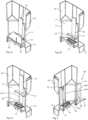
- the Figures 1a and 1b show two oblique views of a first preferred embodiment of the storage container 1 for a storage and delivery station for medicines.
- the Figure 1c shows a top view of the storage container
- Figure 1d shows a detailed view of Figure 1c .
- a cover which is provided in the normal operation of a storage container, has been omitted for better visibility.
- the one in the Figures 1a-1c The storage container according to the invention shown is part of a storage and dispensing station for medicines, whereby, as the name already makes clear, the medicine portions to be separated are stored in the storage container.
- the storage container 1 further comprises a separating device, which is part of a separating mechanism extending over the storage container and a dispensing part, and which is described in more detail with reference to the following figures.
- the dispensing part can, for example, include a control and a drive for the separating device.
- the storage container itself comprises a housing 10 enclosing a receiving space 2 for medication portions (not shown), which includes a guide section 11 in the middle area and a foot section 12 underneath.
- the guide section defines a largely circular cylindrical guide space in which, as described below, the separating device is arranged. "Largely” circular because, as will also be described in more detail below, a guide recess is provided in the guide section, which interrupts a complete circular cylinder inside the guide section.
- the housing of the storage container further comprises a handle 13 with which the storage container 1 can be easily removed from the dispensing part of the supply and dispensing station.
- the guide space 3 or the guide section 11 of the housing is closed at the bottom by a bottom surface 14, which includes a discharge opening 15 and a central opening, with Figure 1c in this central opening a coupling means 35 of the separating device 30 arranged in the guide space 3 (see Figure 2a ) is shown.
- a retaining means is arranged in the right area of the guide section 11 of the housing, the retaining section 41 of which is aligned with the bottom opening 15.
- the retaining section closes a channel aligned with the delivery opening 15, so that no further drug portions can penetrate into the channel aligned with the delivery opening 15 (see also 4a, 4b).
- the retaining means is mounted via a guide means 45 in a guide recess 20 in the guide section 11, the design of the guide recess 20 and the guide means 45 ensuring that the guide means is not displaced radially when the separating device rotates, i.e. does not come into contact with the separating device Moves in the circumferential direction, but is always aligned with the delivery opening.
- Figure 1d shows in detail the exact design of the guide section 11 in the area of the guide recess 20 and the guide means 45.
- the two aforementioned components are coupled to one another via a dovetail connection, which ensures that the guide means 45 is not displaceable radially and in the circumferential direction, in height (i.e. axially) but is movable (i.e. there is a radial and circumferential positive connection).
- a dovetail connection To form the dovetail connection, side walls 24a, 24b defining the guide recess 20 and side walls 49a, 49b delimiting the guide means are designed to be correspondingly conical and taper towards one another inwards.
- Figures 2a-2c show various sectional views of the first embodiment of the storage container according to the invention.
- the retaining section 41 of the retaining means is held above the projections 32 of the separating device 30.
- the vertical guide recess 20 can also be seen in the guide section 11 of the storage container.
- the guide means 45 is held in the guide recess via a dovetail connection.
- the guide recess 20 itself does not penetrate the wall of the guide section 11, so an escape of drug dust is avoided, in contrast to storage containers according to the prior art.
- Figure 3 shows a sectional view of a second preferred embodiment.
- the guide means is not only height-adjustable, but also height-fixable.
- the height fixability is achieved via locking means 43, which are arranged on the rear wall of the guide projection 20 and interact with corresponding locking means (not shown) on or in the side of the guide means facing the rear wall.
- the height fixability can also be achieved by magnetically acting holding means 25, 42, which are arranged in the rear wall and the guide means 45. These can also be used to couple the guide means in the guide projection.
- the magnetic holding means can therefore be used for fixation in the axial, radial and circumferential directions.
- the two aforementioned versions of axial fixation are shown in a drawing or an embodiment for purely descriptive reasons; in purely practical terms, these two types of fixation will usually be used alternatively.
Landscapes
- Mechanical Engineering (AREA)
- Engineering & Computer Science (AREA)
- Physics & Mathematics (AREA)
- General Physics & Mathematics (AREA)
- Health & Medical Sciences (AREA)
- Life Sciences & Earth Sciences (AREA)
- Public Health (AREA)
- Veterinary Medicine (AREA)
- General Health & Medical Sciences (AREA)
- Animal Behavior & Ethology (AREA)
- Chemical & Material Sciences (AREA)
- Medicinal Chemistry (AREA)
- Pharmacology & Pharmacy (AREA)
- Medical Preparation Storing Or Oral Administration Devices (AREA)
- Basic Packing Technique (AREA)
Description
- Die vorliegende Erfindung betrifft einen Vorratsbehälter für eine Vorrats- und Abgabestation für Stückgüter, insbesondere Arzneimittel.
- Moderne Blisterautomaten, wie sie beispielsweise in der
WO 2013/034504 A1 offenbart sind, umfassen, je nach Ausbaustufe, mehrere hundert Vorrats- und Abgabestationen. In diesen sind jeweils eine Mehrzahl von Arzneimittelportionen eines bestimmten Arzneimittels gelagert, und auf Anforderungen können einzelne Arzneimittelportionen abgegeben werden. Mit dem Blisterautomaten werden die in den Vorrats- und Abgabestationen gelagerten Arzneimittelportionen patientenindividuell gemäß den ärztlich verordneten Eingabezeitpunkten zusammengestellt und verblistert. - Zur Zusammenstellung der Arzneimittelportionen werden entsprechende Vorrats- und Abgabestationen zur Abgabe einer oder mehrerer vereinzelter Arzneimittelportionen angesteuert. Bei der Ansteuerung einer Vorrats- und Abgabestation wird mit einer Vereinzelungseinrichtung eine einzelne Arzneimittelportion separiert und über eine Abgabeöffnung einer Führungseinrichtung des Blisterautomaten übergeben. Mittels der Führungseinrichtung wird eine abgegebene Arzneimittelportion, gegebenenfalls unter Zwischenschaltung einer Sammeleinrichtung, einer Verpackungseinrichtung zugeführt, welche einzelne oder mehrere Arzneimittelportionen entsprechend der ärztlichen Vorgabe verblistert.
- Zur Vereinzelung der Arzneimittelportionen, die in einem Vorratsbehälter einer Vorrats- und Abgabestation gelagert sind, umfasst die Vereinzelungseinrichtung einen Rotor mit einer Vielzahl von Kanälen, die üblicherweise am Außenumfang des Rotors angeordnet sind. Die Kanäle sind an die jeweils zu separierenden Arzneimittelportionen hinsichtlich ihrer Abmessungen derart angepasst, dass in einem Kanal die Arzneimittelportionen lediglich übereinander, nicht aber nebeneinander angeordnet sein können. Die Kanäle können auch derart bemessen sein, dass in einen Kanal lediglich eine Arzneimittelportion aufgenommen werden kann.
- Zur Abgabe einer Arzneimittelportion aus einem Kanal wird ein Kanal über eine Abgabeöffnung in dem Gehäuse des Vorratsbehälters bewegt, und die in dem Kanal an unterster Stelle angeordnete Arzneimittelportion rutscht bzw. fällt in die Abgabeöffnung. Um zu vermeiden, dass weitere in dem oder über dem Kanal lagernde Arzneimittelportionen ebenfalls abgegeben werden, ist in dem Bereich über der Abgabeöffnung ein Rückhalteabschnitt eines Rückhaltemittels zumindest in oder über den Kanal geführt bzw. angeordnet, der an der Abgabeöffnung ausgerichtet ist. Dieser Rückhalteabschnitt ist in Bezug auf die Höhe des Kanals derart in diesem oder über diesem angeordnet, dass unter dem Rückhalteabschnitt lediglich eine Arzneimittelportion angeordnet sein kann. Sofern der Rückhalteabschnitt in den Kanal geführt ist, um die unterste Arzneimittelportion von darüber angeordneten zu trennen, weisen einzelne Kanäle separierende Vorsprünge einen Schlitz auf, welcher den Rückhalteabschnitt aufnimmt. Sofern der Rückhalteabschnitt über den Kanälen angeordnet bzw. geführt ist, ist dieser regelmäßig nur geringfügig über den oberen Enden der Vorsprünge geführt, so dass vermieden wird, dass bei Abgabe der Arzneimittelportion weitere Arzneimittelportionen in den Kanal gelangen.
- Der Rückhalteabschnitt des Rückhaltemittels ist bei bekannten Vorrats- und Abgabestationen von außen durch einen horizontalen Gehäuseschlitz in den Vorratsbehälter geführt, und zwar derart, dass der Rückhalteabschnitt, in Abhängigkeit von der Gestaltung der Kanäle, über diesen oder in einem Schlitz in den Kanälen angeordnet ist. Wie bereits oben dargelegt, sind die Kanäle und damit die die Kanäle definierenden Vorsprünge an die Abmessungen der jeweils zu vereinzelnden Arzneimittelportionen angepasst. Dies bedeutet unter anderem, dass die Vorsprünge bei unterschiedlichen Arzneimittelportionen unterschiedlich hoch sind. Können mehrere Arzneimittelportionen in einem Kanal aufgenommen werden, ist auch die Lage des Schlitzes, in welchen der Rückhalteabschnitt des Rückhaltemittels eingreift, von den Abmessungen der Arzneimittelportionen abhängig. Dies bedingt, dass die Position des horizontalen Schlitzes in dem Gehäuse ebenfalls von den Abmessungen der Arzneimittelportionen abhängig ist, so dass bei unterschiedlichen Arzneimittelportionen unterschiedliche Gehäuse zu verwenden sind. Mit anderen Worten, das gleiche Gehäuse kann nicht mit Arzneimittelportionen mit unterschiedlichen Abmessungen genutzt werden.
- Die
WO 2015/068973 A1 offenbart einen Tablettenbehälter mit einem variablen Teilungsblock. Der Tablettenbehälter umfasst einen Aufbewahrungsteil, in dem eine Tablette aufbewahrt wird, und einen Teilungsblock, der sich um eine zentrale Achse dreht und eine Vielzahl von Unterteilungselementen umfasst, die in einem vorbestimmten Abstand voneinander um eine äußere Umfangsfläche davon angeordnet sind. Ein Tablettenaufnahmeteil, der durch einen Zwischenraum zwischen den Trennelementen definiert ist, nimmt die Tablette auf, die aus dem Aufbewahrungsteil fällt. Der Tablettenbehälter umfasst auch ein Gehäuse mit einer darin definierten Auslassöffnung, durch die die im Tablettenaufnahmeteil aufgenommene Tablette nach außen abgegeben wird. Jedes der Trennelemente ist von der äußeren Umfangsfläche des Teilungsblocks abnehmbar. - Aus der
US 2015/0090733 A1 ist ein Vorratsbehälter mit einem höhenverstellbaren Rückhaltemittel bekannt, wobei ein Abschnitt des Rückhaltemittels durch einen vertikalen Schlitz in dem Gehäuse geführt ist. Auch aus derEP 2 752 181 A2 ist ein Vorratsbehälter mit einem höhenverstellbaren Rückhaltemittel bekannt, das aber in einer Abdeckung geführt ist, die in einer Gehäuseöffnung angeordnet ist. - Es ist daher Aufgabe der vorliegenden Erfindung, einen konstruktiv einfachen Vorratsbehälter für eine Vorrats- und Abgabestation bereitzustellen, welcher für Arzneimittelportionen mit unterschiedlichen Abmessungen genutzt werden kann und bei welchem kein Arzneimittelstaub austreten kann.
- Die Aufgabe wird gelöst durch einen Vorratsbehälter gemäß Patentanspruch 1 oder 2. Der erfindungsgemäße Vorratsbehälter für eine Vorrats- und Abgabestation für Arzneimittel umfasst ein einen Aufnahmeraum für Arzneimittelportionen umschließendes Gehäuse mit einem Führungsabschnitt und einer Bodenfläche, wobei der Führungsabschnitt einen üblicherweise kreiszylinderförmigen Führungsraum definiert und einen das Gehäuse nicht durchdringenden vertikalen Führungsrücksprung aufweist und wobei die Bodenfläche eine Abgabeöffnung aufweist. Der Vorratsbehälter umfasst ferner eine in dem Führungsabschnitt des Gehäuses angeordnete Vereinzelungseinrichtung mit zumindest einem Kanal zur Aufnahme zumindest einer Arzneimittelportion sowie ein Rückhaltemittel mit einem Rückhalteabschnitt, wobei das Gehäuse keinen Schlitz aufweist und der Rückhalteabschnitt vollständig innerhalb des Führungsabschnitts angeordnet und oberhalb der Abgabeöffnung gehalten ist und einen Eintritt weiterer Arzneimittelportionen in einen an der Abgabeöffnung ausgerichteten Kanal verhindert. Ob der Rückhalteabschnitt des Rückhaltemittels über dem zumindest einen Kanal oder in einem Schlitz von den Kanälen definierenden Vorsprüngen gehalten bzw. geführt ist, ist abhängig von der genauen Gestaltung der Kanäle und hat keinen Einfluss auf die Erfindung als solche.
- Das Rückhaltemittel umfasst ferner ein Führungsmittel, wobei das Führungsmittel in dem vertikalen Führungsrücksprung angeordnet ist und wobei der vertikale Führungsrücksprung und das Führungsmittel derart zusammenwirken, dass das Rückhaltemittel höhenverstellbar in der Führungsausnehmung angeordnet bzw. gelagert ist und gleichzeitig eine Drehbewegung bzw. eine kreisförmige Bewegung des Rückhaltemittels verhindert wird.
- Das Rückhaltemittel ist innerhalb des Vorratsbehälters höhenverstellbar, wozu ein vertikaler Führungsrücksprung in dem Führungsabschnitt vorgesehen ist, wobei der Führungsrücksprung mit einem entsprechenden Führungsmittel des Rückhalteabschnittes zusammenwirkt, um die notwendige Höhenverstellbarkeit zu gewährleisten. Der vertikale Führungsrücksprung und das Führungsmittel sind so ausgebildet, dass ein radialer Versatz und eine Umfangsbewegung bzw. kreisförmige Bewegung des Führungsmittels innerhalb des Führungsabschnitts bzw. Führungsraums vermieden wird. Dass diese Bewegung verhindert wird, ist wesentlich, da der Rückhalteabschnitt des Rückhaltemittels stets an bzw. in dem Kanal ausgerichtet bzw. angeordnet sein muss, der an der Abgabeöffnung in der Bodenfläche ausgerichtet ist.
- Bei dem erfindungsgemäßen Vorratsbehälter ist kein Schlitz in dem Gehäuse vorgesehen. Das hat den Vorteil, dass kein sich in der Vorrats- und Abgabestation bildender Arzneimittelstaub bzw. -abrieb nach außen treten kann. Dies ist insbesondere vor dem Hintergrund wesentlich, dass moderne Blisterautomaten gelegentlich in hochreinen Räumen verwendet werden, bei welchen ein Austritt von Arzneimittelabrieb einen erhöhten Reinigungsbedarf bedingt.
- Die genaue Ausbildung des Führungsrücksprungs und des Führungsmittels sind nicht erfindungswesentlich, solange es gewährleistet ist, dass das Rückhaltemittel über die Kombination Führungsrücksprung/Führungsmittel einerseits höhenverstellbar ist, andererseits radial und am Umfang bzw. kreisförmig nicht bewegbar ist.
- Erfindungsgemäß sind das Führungsmittel und der Führungsrücksprung über eine Schwalbenschwanzverbindung gekoppelt. Alternativ ist es vorgesehen, dass das Führungsmittel und der Führungsrücksprung über magnetische Haltemittel gekoppelt sind. Wenn der Rückhalteabschnitt in einem Schlitz der Vorsprünge der Vereinzelungseinrichtung gehalten ist, kann es auch ausreichend sein, wenn die Seitenflächen des Führungsrücksprungs senkrecht parallel zueinander ausgebildet sind. Die beiden vorgenannten Alternativen sind konstruktiv einfach gehalten.
- Der Führungsrücksprung durchdringt das Gehäuse bzw. den Führungsabschnitt nicht. Um zu vermeiden, dass das Gehäuse im gesamten Bereich des Führungsabschnitts eine Wandstärke aufweist, die die Ausbildung eines Rücksprungs ermöglicht, ist es erfindungsgemäß vorgesehen, dass das Gehäuse (lediglich) im Bereich des Führungsabschnitts einen Vorsprung (also eine Gehäusewandverstärkung) aufweist, in welchem der Führungsrücksprung angeordnet ist.
- Das Führungsmittel ist in dem Führungsrücksprung höhenverstellbar angeordnet. Schwerkraftbedingt liegt der Rückhalteabschnitt entweder auf der Vereinzelungseinrichtung auf oder ist in einem horizontalen Schlitz, der die Vorsprünge teilt, gehalten. Mit anderen Worten, das Führungsmittel ist in dem Führungsabschnitt zwar höhenverstellbar, aber nicht unbedingt höhenfixierbar angeordnet. Um auch eine Höhenfixierbarkeit zu ermöglichen, kann es bei einer bevorzugten Ausführungsform vorgesehen sein, dass der Führungsrücksprung und das Führungsmittel Rastmittel aufweisen, die eine solche Höhenfixierbarkeit ermöglichen.
- Erfindungsgemäß ist das Führungsmittel in dem Führungsrücksprung angeordnet, welcher wiederrum in dem Führungsabschnitt ausgebildet ist. Der Führungsabschnitt definiert den üblicherweise kreiszylinderförmigen Führungsraum. Konstruktionsbedingt verhält es sich also so, dass der Führungsrücksprung den ansonsten kreiszylinderförmigen Führungsraum "unterbricht". Um zu vermeiden, dass diese Unterbrechung Arzneimittelportionen beschädigt oder sich Staub in dieser ansammelt, ist es bei einer bevorzugten Ausführungsform vorgesehen, dass die dem Führungsraum zugewandte Oberfläche des Führungsmittels eine kreiszylinderförmige Kontur aufweist.
- Im Nachfolgenden werden bevorzugte Ausführungsformen des erfindungsgemäßen Vorratsbehälters für Vorrats- und Abgabestationen unter Bezugnahme auf die beigefügte Zeichnung beschrieben, in welcher
-
Figuren 1a-1d verschiedene Ansichten einer ersten bevorzugten Ausführungsform des erfindungsgemäßen Vorratsbehälters zeigen; -
Figuren 2a-2c verschiedene Schnittansichten der ersten Ausführungsform des Vorratsbehälters zeigen, und -
Figur 3 eine Schnittansicht einer zweiten bevorzugten Ausführungsform zeigt. - Die
Figuren 1a und 1b zeigen zwei Schrägansichten einer ersten bevorzugten Ausführungsform des Vorratsbehälters 1 für eine Vorrats- und Abgabestation für Arzneimittel. DieFigur 1c zeigt eine Draufsicht auf den Vorratsbehälter, undFigur 1d zeigt eine Detailansicht vonFigur 1c . Bei sämtlichen Darstellungen des Vorratsbehälters ist zur besseren Einsicht eine Abdeckung fortgelassen, die im üblichen Betrieb eines Vorratsbehälters vorgesehen ist. Der in denFiguren 1a-1c gezeigte erfindungsgemäße Vorratsbehälter ist Teil einer Vorrats- und Abgabestation für Arzneimittel, wobei, wie dies bereits der Name verdeutlich, in dem Vorratsbehälter die zu vereinzelnden Arzneimittelportionen gelagert sind. Der Vorratsbehälter 1 umfasst ferner eine Vereinzelungseinrichtung, die Teil einer sich über den Vorratsbehälter und einen Abgabeteil erstreckenden Vereinzelungsmechanik ist, und die unter Bezugnahme auf nachfolgende Figuren genauer beschrieben wird. Das Abgabeteil kann beispielsweise eine Steuerung und einen Antrieb für die Vereinzelungseinrichtung umfassen. - Der Vorratsbehälter selbst umfasst ein einen Aufnahmeraum 2 für (nicht dargestellte) Arzneimittelportionen umschließendes Gehäuse 10, welches im mittleren Bereich einen Führungsabschnitt 11 und darunter einen Fußabschnitt 12 umfasst. Der Führungsabschnitt definiert einen weitgehend kreiszylinderförmigen Führungsraum, in welchem, wie dies weiter unten beschrieben ist, die Vereinzelungseinrichtung angeordnet ist. "Weitgehend" kreisförmig deshalb, weil, wie dies ebenfalls weiter unten detaillierter beschrieben wird, in dem Führungsabschnitt ein Führungsrücksprung vorgesehen ist, der einen vollständigen Kreiszylinder im Inneren des Führungsabschnitts unterbricht. Das Gehäuse des Vorratsbehälters umfasst ferner einen Griff 13, mit dem der Vorratsbehälter 1 einfach von dem Abgabeteil der Vorrats- und Abgabestation heruntergenommen werden kann.
- Wie dies in
Figur 1c zu erkennen ist, ist der Führungsraum 3 bzw. der Führungsabschnitt 11 des Gehäuses nach unten durch eine Bodenfläche 14 abgeschlossen, die eine Abgabeöffnung 15 sowie eine zentrale Öffnung umfasst, wobei beiFigur 1c in dieser zentralen Öffnung ein Kopplungsmittel 35 der in dem Führungsraum 3 angeordneten Vereinzelungseinrichtung 30 (sieheFigur 2a ) dargestellt ist. - Bei
Figur 1c ist im rechten Bereich des Führungsabschnitts 11 des Gehäuses ein Rückhaltemittel angeordnet, dessen Rückhalteabschnitt 41 an der Bodenöffnung 15 ausgerichtet ist. Der Rückhalteabschnitt verschließt einen an der Abgabeöffnung 15 ausgerichteten Kanal, so dass keine weiteren Arzneimittelportionen in den an der Abgabeöffnung 15 ausgerichteten Kanal eindringen können (siehe dazu auch 4a, 4b). Das Rückhaltemittel ist über ein Führungsmittel 45 in einem Führungsrücksprung 20 in Führungsabschnitt 11 gelagert, wobei die Ausbildung des Führungsrücksprungs 20 sowie des Führungsmittels 45 dafür Sorge tragen, dass das Führungsmittel bei einer Drehung der Vereinzelungseinrichtung radial nicht versetzt wird, sprich sich nicht mit der Vereinzelungseinrichtung in Umfangsrichtung bewegt, sondern stets an der Abgabeöffnung ausgerichtet ist. -
Figur 1d zeigt im Detail die genaue Ausgestaltung des Führungsabschnitts 11 im Bereich des Führungsrücksprungs 20 sowie des Führungsmittels 45. Die beiden vorgenannten Bauteile sind über eine Schwalbenschwanzverbindung miteinander gekoppelt, die dafür Sorge trägt, dass das Führungsmittel 45 radial und in Umfangsrichtung nicht verschiebbar ist, in der Höhe (also axial) jedoch bewegbar ist (also eine radial und umfangsmäßig formschlüssige Verbindung vorliegt). Zur Ausbildung der Schwalbenschwanzverbindung sind den Führungsrücksprung 20 definierende Seitenwände 24a, 24b sowie das Führungsmittel begrenzende Seitenwände 49a, 49b entsprechend konisch, nach innen aufeinander zulaufend ausgebildet. -
Figuren 2a-2c zeigen verschiedene Schnittansichten der ersten Ausführungsform des erfindungsgemäßen Vorratsbehälters. BeiFigur 2a ist zu erkennen, dass der Rückhalteabschnitt 41 des Rückhaltemittels über den Vorsprüngen 32 der Vereinzelungseinrichtung 30 gehalten ist. Bei denFiguren 2a-2c ist ebenfalls die vertikale Führungsausnehmung 20 in dem Führungsabschnitt 11 des Vorratsbehälters zu erkennen. Bei der gezeigten Ausführungsform ist das Führungsmittel 45 über eine Schwalbenschwanzverbindung in dem Führungsrücksprung gehalten. Der Führungsrücksprung 20 selbst durchdringt die Wandung des Führungsabschnitts 11 nicht, ein Austritt von Arzneimittelstaub wird also, im Gegensatz zu Vorratsbehältern nach dem Stand der Technik, vermieden. -
Figur 3 zeigt eine Schnittansicht einer zweiten bevorzugten Ausführungsform. Bei dieser zweiten Ausführungsform ist das Führungsmittel nicht nur höhenverstellbar, sondern auch höhenfixierbar. Die Höhenfixierbarkeit wird erreicht über Rastmittel 43, die an der Rückwand des Führungsvorsprungs 20 angeordnet sind und mit entsprechenden (nicht dargestellten) Rastmitteln an bzw. in der der Rückwand zugewandten Seite des Führungsmittels zusammenwirken. Die Höhenfixierbarkeit kann ferner durch magnetisch wirkende Haltemittel 25, 42 erzielt werden, die in der Rückwand und dem Führungsmittel 45 angeordnet sind. Diese können auch für eine Kopplung des Führungsmittels in dem Führungsvorsprung verwendet werden. Die magnetischen Haltemittel können also für eine Fixierung in axialer, radialer und in Umfangsrichtung genutzt werden. Die beiden vorgenannten Ausführungen der axialen Fixierung sind aus rein beschreibungstechnischen Gründen in einer Zeichnung bzw. einer Ausführungsform dargestellt, rein praktisch werden diese beiden Arten der Fixierung üblicherweise wohl alternativ verwendet werden.
Claims (4)
- Vorratsbehälter (1) für eine Vorrats- und Abgabestation für Arzneimittel, aufweisend:ein einen Aufnahmeraum (2) für Arzneimittelportionen umschließendes Gehäuse (10) mit einem Führungsabschnitt (11) und einer Bodenfläche (14), wobei der Führungsabschnitt (11) einen Führungsraum (3) definiert und einen das Gehäuse nicht durchdringenden vertikalen Führungsrücksprung (20) aufweist und wobei die Bodenfläche (14) eine Abgabeöffnung (15) aufweist,eine in dem Führungsraum (3) des Gehäuses (10) angeordnete Vereinzelungseinrichtung (30) mit zumindest einem Kanal (31) zur Aufnahme zumindest einer Arzneimittelportion, undein Rückhaltemittel (40) miteinem Rückhalteabschnitt (41), wobei das Gehäuse (10) keinen Schlitz aufweist und der Rückhalteabschnitt (41) vollständig innerhalb des Führungsraums (3) angeordnet und oberhalb der Abgabeöffnung (15) gehalten ist und einen Eintritt weiterer Arzneimittelportionen in einen an der Abgabeöffnung (15) ausgerichteten Kanal (31) verhindert, undeinem Führungsmittel (45), wobei das Führungsmittel (45) in dem Führungsrücksprung (20) angeordnet ist und wobei der vertikale Führungsrücksprung (20) und das Führungsmittel (45) derart zusammenwirken, dass das Rückhaltemittel (40) über das Führungsmittel (45) höhenverstellbar im Führungsrücksprung (20) angeordnet ist und eine Drehbewegung des Rückhaltemittels (40) verhindert ist,dadurch gekennzeichnet, dass das Führungsmittel (45) und der Führungsrücksprung (20) über eine Schwalbenschwanzverbindung (49a, 49b, 24a, 24b) gekoppelt sind, und dass das Gehäuse (10) im Bereich des Führungsabschnitts (11) einen Vorsprung (11b) aufweist, in welchem der Führungsrücksprung (20) angeordnet ist.
- Vorratsbehälter (1) für eine Vorrats- und Abgabestation für Arzneimittel, aufweisend:ein einen Aufnahmeraum (2) für Arzneimittelportionen umschließendes Gehäuse (10) mit einem Führungsabschnitt (11) und einer Bodenfläche (14), wobei der Führungsabschnitt (11) einen Führungsraum (3) definiert und einen das Gehäuse nicht durchdringenden vertikalen Führungsrücksprung (20) aufweist und wobei die Bodenfläche (14) eine Abgabeöffnung (15) aufweist,eine in dem Führungsraum (3) des Gehäuses (10) angeordnete Vereinzelungseinrichtung (30) mit zumindest einem Kanal (31) zur Aufnahme zumindest einer Arzneimittelportion, undein Rückhaltemittel (40) miteinem Rückhalteabschnitt (41), wobei das Gehäuse (10) keinen Schlitz aufweist und der Rückhalteabschnitt (41) vollständig innerhalb des Führungsraums (3) angeordnet und oberhalb der Abgabeöffnung (15) gehalten ist und einen Eintritt weiterer Arzneimittelportionen in einen an der Abgabeöffnung (15) ausgerichteten Kanal (31) verhindert, undeinem Führungsmittel (45), wobei das Führungsmittel (45) in dem Führungsrücksprung (20) angeordnet ist und wobei der vertikale Führungsrücksprung (20) und das Führungsmittel (45) derart zusammenwirken, dass das Rückhaltemittel (40) über das Führungsmittel (45) höhenverstellbar im Führungsrücksprung (20) angeordnet ist und eine Drehbewegung des Rückhaltemittels (40) verhindert ist,dadurch gekennzeichnet, dass das Führungsmittel (45) und der Führungsrücksprung (20) über magnetisch wirkende Haltemittel (25, 42) gekoppelt sind, und dass das Gehäuse (10) im Bereich des Führungsabschnitts (11) einen Vorsprung (11b) aufweist, in welchem der Führungsrücksprung (20) angeordnet ist.
- Vorratsbehälter (1) für eine Vorrats- und Abgabestation für Arzneimittel nach einem der Ansprüche 1 oder 2, dadurch gekennzeichnet, dass der Führungsrücksprung (20) und das Führungsmittel (45) Rastmittel (43) aufweisen.
- Vorratsbehälter (1) für eine Vorrats- und Abgabestation für Arzneimittel nach einem der Ansprüche 1 - 3, dadurch gekennzeichnet, dass der Führungsraum (3) kreiszylinderförmig ist und die dem Führungsraum (3) zugewandte Oberfläche des Führungsmittels (45) eine kreiszylinderförmige Kontur aufweist.
Applications Claiming Priority (2)
| Application Number | Priority Date | Filing Date | Title |
|---|---|---|---|
| EP17166081.4A EP3389022A1 (de) | 2017-04-11 | 2017-04-11 | Vorratsbehälter für eine vorrats- und abgabestation |
| PCT/EP2018/053747 WO2018188837A1 (de) | 2017-04-11 | 2018-02-15 | Vorratsbehälter für eine vorrats- und abgabestation |
Publications (2)
| Publication Number | Publication Date |
|---|---|
| EP3610468A1 EP3610468A1 (de) | 2020-02-19 |
| EP3610468B1 true EP3610468B1 (de) | 2023-10-18 |
Family
ID=58547341
Family Applications (2)
| Application Number | Title | Priority Date | Filing Date |
|---|---|---|---|
| EP17166081.4A Withdrawn EP3389022A1 (de) | 2017-04-11 | 2017-04-11 | Vorratsbehälter für eine vorrats- und abgabestation |
| EP18706983.6A Active EP3610468B1 (de) | 2017-04-11 | 2018-02-15 | Vorratsbehälter für eine vorrats- und abgabestation |
Family Applications Before (1)
| Application Number | Title | Priority Date | Filing Date |
|---|---|---|---|
| EP17166081.4A Withdrawn EP3389022A1 (de) | 2017-04-11 | 2017-04-11 | Vorratsbehälter für eine vorrats- und abgabestation |
Country Status (8)
| Country | Link |
|---|---|
| US (2) | US11383866B2 (de) |
| EP (2) | EP3389022A1 (de) |
| JP (1) | JP7022146B2 (de) |
| KR (1) | KR102498437B1 (de) |
| CN (1) | CN110506302B (de) |
| AU (1) | AU2018251021B2 (de) |
| CA (1) | CA3058495A1 (de) |
| WO (1) | WO2018188837A1 (de) |
Families Citing this family (7)
| Publication number | Priority date | Publication date | Assignee | Title |
|---|---|---|---|---|
| EP3926594B1 (de) * | 2020-06-16 | 2025-03-05 | Becton Dickinson Rowa Germany GmbH | Vorratsbehälter für eine vorrats- und abgabestation |
| EP3925590B1 (de) | 2020-06-16 | 2025-01-08 | Becton Dickinson Rowa Germany GmbH | Vorratsbehälter für eine vorrats- und abgabestation |
| US11352194B2 (en) * | 2020-06-16 | 2022-06-07 | Becton Dickinson Rowa Germany Gmbh | Storage container for a storage and dispensing station |
| US11390404B2 (en) | 2020-07-31 | 2022-07-19 | Becton Dickinson Rowa Germany Gmbh | Storage container for a storage and dispensing station |
| EP3945504B1 (de) * | 2020-07-31 | 2024-10-30 | Becton Dickinson Rowa Germany GmbH | Vorratsbehälter für eine vorrats- und abgabestation |
| EP4524043B1 (de) * | 2023-09-18 | 2026-02-11 | Becton Dickinson Rowa Germany GmbH | Vorratsbehälter für eine vorrats- und abgabestation und verfahren zum anpassen des vorratsbehälters |
| EP4585525A1 (de) * | 2024-01-09 | 2025-07-16 | Becton Dickinson Rowa Germany GmbH | Vorratsbehälter für eine vorrats- und abgabestation für einen blisterautomaten sowie verfahren zum anpassen des vorratsbehälters |
Citations (5)
| Publication number | Priority date | Publication date | Assignee | Title |
|---|---|---|---|---|
| JP2002272812A (ja) * | 2001-03-16 | 2002-09-24 | Tosho Inc | 調剤システム |
| US20070150092A1 (en) * | 2004-01-05 | 2007-06-28 | Tosho Inc. | Automatic dispensation device and medicine |
| EP2664316A1 (de) * | 2011-01-14 | 2013-11-20 | Yuyama Mfg. Co., Ltd. | Tablettenkassette |
| EP2804156A1 (de) * | 2013-05-14 | 2014-11-19 | Infopia Co., Ltd. | Pillenkartusche für medizinische Verpackungsvorrichtung |
| US20150090733A1 (en) * | 2013-10-01 | 2015-04-02 | PharmRight Corporation | Device for Dispensing Pharmaceutical Doses |
Family Cites Families (31)
| Publication number | Priority date | Publication date | Assignee | Title |
|---|---|---|---|---|
| US3128011A (en) * | 1961-09-20 | 1964-04-07 | Howard W Bleiman | Coin operated vending machine |
| US5191998A (en) * | 1992-05-08 | 1993-03-09 | Schwarzli Josef W | Brush housing for bulk vendor |
| JP3472018B2 (ja) * | 1996-03-04 | 2003-12-02 | 高園産業株式会社 | 錠剤等の薬剤選択供給装置用の薬剤収容容器 |
| JP4298834B2 (ja) | 1999-01-14 | 2009-07-22 | 株式会社湯山製作所 | 錠剤フィーダ |
| JP2002153541A (ja) * | 2000-11-20 | 2002-05-28 | Tosho Inc | 薬剤フィーダ |
| WO2003016138A1 (fr) * | 2001-08-20 | 2003-02-27 | Yuyama Mfg. Co., Ltd. | Dispositif de distribution de comprimes |
| JP4398759B2 (ja) * | 2004-03-03 | 2010-01-13 | 株式会社トーショー | 薬剤フィーダおよびその集合体 |
| US20060037125A1 (en) * | 2004-08-23 | 2006-02-23 | Mcdowell Anthony | Binocular to hat attachment |
| EP3064190B1 (de) * | 2008-09-18 | 2018-11-21 | Yuyama Mfg. Co., Ltd. | Tablettenzuführvorrichtung |
| WO2010066456A1 (en) | 2008-12-12 | 2010-06-17 | Dsm Ip Assets B.V. | Dispenser |
| EP2572995B1 (de) * | 2010-05-17 | 2016-07-06 | Yuyama Mfg. Co., Ltd. | Tablettenkassette |
| KR101209849B1 (ko) * | 2010-11-26 | 2012-12-10 | (주)크레템 | 약제 포장 장치의 정제 카세트 |
| EP2649980A4 (de) * | 2010-12-09 | 2017-09-20 | Yuyama Mfg. Co., Ltd. | Arzneimittelspender und arzneimittelzähler |
| JP5957747B2 (ja) * | 2011-02-01 | 2016-07-27 | 株式会社タカゾノテクノロジー | 錠剤カセッター |
| CN202046589U (zh) | 2011-04-02 | 2011-11-23 | 肇庆市正康电子科技有限公司 | 全自动配药机药盒 |
| NL2007384C2 (nl) | 2011-09-09 | 2013-03-12 | Ppm Engineering B V | Systeem en werkwijze voor het verpakken van gedoseerde hoeveelheden vaste medicijnen. |
| DE112012003805A5 (de) * | 2011-09-13 | 2014-05-28 | Vita-Spend Gmbh | Einstellbarer Tablettenspender zur Vereinzelung von Tabletten mit unterschiedlichen Abmessungen |
| KR101449717B1 (ko) | 2013-01-02 | 2014-10-15 | 주식회사 인포피아 | 약제 포장장치용 정제 카트리지 |
| KR102044473B1 (ko) * | 2013-05-30 | 2019-11-12 | 삼성전자주식회사 | 포장 상자 |
| JP6000195B2 (ja) * | 2013-07-03 | 2016-09-28 | 株式会社トーショー | 錠剤カセット |
| JP5950876B2 (ja) * | 2013-07-25 | 2016-07-13 | 株式会社トーショー | 薬剤フィーダ |
| CA2923965A1 (en) * | 2013-09-20 | 2015-03-26 | Takazono Technology Incorporated | Medicine feeding unit |
| EP3056184A4 (de) * | 2013-10-09 | 2017-06-28 | Takazono Technology Incorporated | Medizinfüllvorrichtung |
| KR101652152B1 (ko) * | 2013-11-08 | 2016-08-29 | (주)제이브이엠 | 가변 디비전 블록을 구비한 정제 캐니스터 |
| US9663260B2 (en) * | 2014-01-31 | 2017-05-30 | Yuyama Mfg. Co., Ltd. | Drug feeder |
| DK2962956T3 (en) * | 2014-07-03 | 2017-01-23 | Becton Dickinson Rowa Germany Gmbh | Storage container for a device for the automated dispensing of individual drug portions |
| US10421566B2 (en) * | 2014-07-03 | 2019-09-24 | Carefusion Germany 326 Gmbh | Storage container for automated dispensing of individual medicament portions |
| US10583979B2 (en) * | 2015-10-12 | 2020-03-10 | Carefusion Germany 326 Gmbh | Storage container for drug dispensing and storage stations |
| US10028888B2 (en) * | 2016-01-29 | 2018-07-24 | Carefusion Germany 326 Gmbh | Storage container for a storage and delivery station for drugs |
| WO2019163854A1 (ja) * | 2018-02-21 | 2019-08-29 | 株式会社トーショー | 錠剤カセット |
| US11745954B2 (en) * | 2018-12-13 | 2023-09-05 | Yuyama Mfg. Co., Ltd. | Rotor for tablet cassette and tablet cassette |
-
2017
- 2017-04-11 EP EP17166081.4A patent/EP3389022A1/de not_active Withdrawn
-
2018
- 2018-02-15 CN CN201880024096.1A patent/CN110506302B/zh active Active
- 2018-02-15 AU AU2018251021A patent/AU2018251021B2/en active Active
- 2018-02-15 WO PCT/EP2018/053747 patent/WO2018188837A1/de not_active Ceased
- 2018-02-15 KR KR1020197031529A patent/KR102498437B1/ko active Active
- 2018-02-15 CA CA3058495A patent/CA3058495A1/en active Pending
- 2018-02-15 US US16/604,025 patent/US11383866B2/en active Active
- 2018-02-15 JP JP2019555179A patent/JP7022146B2/ja active Active
- 2018-02-15 EP EP18706983.6A patent/EP3610468B1/de active Active
-
2022
- 2022-06-07 US US17/834,587 patent/US11661222B2/en active Active
Patent Citations (5)
| Publication number | Priority date | Publication date | Assignee | Title |
|---|---|---|---|---|
| JP2002272812A (ja) * | 2001-03-16 | 2002-09-24 | Tosho Inc | 調剤システム |
| US20070150092A1 (en) * | 2004-01-05 | 2007-06-28 | Tosho Inc. | Automatic dispensation device and medicine |
| EP2664316A1 (de) * | 2011-01-14 | 2013-11-20 | Yuyama Mfg. Co., Ltd. | Tablettenkassette |
| EP2804156A1 (de) * | 2013-05-14 | 2014-11-19 | Infopia Co., Ltd. | Pillenkartusche für medizinische Verpackungsvorrichtung |
| US20150090733A1 (en) * | 2013-10-01 | 2015-04-02 | PharmRight Corporation | Device for Dispensing Pharmaceutical Doses |
Also Published As
| Publication number | Publication date |
|---|---|
| AU2018251021B2 (en) | 2022-11-17 |
| JP2020516365A (ja) | 2020-06-11 |
| US11383866B2 (en) | 2022-07-12 |
| US11661222B2 (en) | 2023-05-30 |
| US20200031509A1 (en) | 2020-01-30 |
| AU2018251021A1 (en) | 2019-11-07 |
| EP3610468A1 (de) | 2020-02-19 |
| BR112019020620A2 (pt) | 2020-04-22 |
| KR20190134678A (ko) | 2019-12-04 |
| EP3389022A1 (de) | 2018-10-17 |
| CA3058495A1 (en) | 2018-10-18 |
| US20230081684A1 (en) | 2023-03-16 |
| WO2018188837A1 (de) | 2018-10-18 |
| JP7022146B2 (ja) | 2022-02-17 |
| KR102498437B1 (ko) | 2023-02-10 |
| CN110506302A (zh) | 2019-11-26 |
| CN110506302B (zh) | 2022-04-15 |
Similar Documents
| Publication | Publication Date | Title |
|---|---|---|
| EP3610468B1 (de) | Vorratsbehälter für eine vorrats- und abgabestation | |
| EP3925590B1 (de) | Vorratsbehälter für eine vorrats- und abgabestation | |
| EP2962956B1 (de) | Vorratsbehälter für eine Vorrichtung zum automatisierten Abgeben einzelner Medikamentenportionen | |
| EP3016885B1 (de) | Vorrichtung und verfahren zum vereinzelnden dosieren von festkörperportionen | |
| DE2647620A1 (de) | Vorrichtung zum ausrichten und fuellen von kapseln | |
| DE112012002816T5 (de) | Tablettenausgabevorrichtung | |
| EP3407854A1 (de) | Vorratsbehälter für eine vorrats- und abgabestation für arzneimittel | |
| EP0290972A1 (de) | Behältnis zur einzel-portionierten Ausgabe von Tabletten | |
| WO2021254738A1 (de) | Vorratsbehälter für eine vorrats- und abgabestation | |
| EP3156338B1 (de) | Vorratsbehälter für eine vorrats- und abgabestation für arzneimittel | |
| EP3945504B1 (de) | Vorratsbehälter für eine vorrats- und abgabestation | |
| EP3926594B1 (de) | Vorratsbehälter für eine vorrats- und abgabestation | |
| WO2012136413A1 (de) | Transportvorrichtung | |
| EP3616675B1 (de) | Vorratsbehälter für eine vorrats- und abgabestation für arzneimittel | |
| EP3343521A1 (de) | Vorratsbehälter für eine vorrats- und abgabestation für arzneimittelportionen | |
| EP4524043B1 (de) | Vorratsbehälter für eine vorrats- und abgabestation und verfahren zum anpassen des vorratsbehälters | |
| EP4067245B1 (de) | Vorrats- und abgabestation für einen blisterautomaten | |
| EP3879503A1 (de) | Vorrats- und abgabestation für arzneimittel | |
| EP4585525A1 (de) | Vorratsbehälter für eine vorrats- und abgabestation für einen blisterautomaten sowie verfahren zum anpassen des vorratsbehälters | |
| DE102014110020B4 (de) | Spender für portionierbares Gut, insbesondere für Tabletten | |
| EP4434903A1 (de) | Vorratsbehälter für eine vorrats- und abgabestation für einen blisterautomaten und verfahren zum vereinzeln von kleinstückgütern | |
| DE3215520A1 (de) | Dose zur portionierten ausgabe von stueckigem gut |
Legal Events
| Date | Code | Title | Description |
|---|---|---|---|
| STAA | Information on the status of an ep patent application or granted ep patent |
Free format text: STATUS: UNKNOWN |
|
| STAA | Information on the status of an ep patent application or granted ep patent |
Free format text: STATUS: THE INTERNATIONAL PUBLICATION HAS BEEN MADE |
|
| PUAI | Public reference made under article 153(3) epc to a published international application that has entered the european phase |
Free format text: ORIGINAL CODE: 0009012 |
|
| STAA | Information on the status of an ep patent application or granted ep patent |
Free format text: STATUS: REQUEST FOR EXAMINATION WAS MADE |
|
| 17P | Request for examination filed |
Effective date: 20191111 |
|
| AK | Designated contracting states |
Kind code of ref document: A1 Designated state(s): AL AT BE BG CH CY CZ DE DK EE ES FI FR GB GR HR HU IE IS IT LI LT LU LV MC MK MT NL NO PL PT RO RS SE SI SK SM TR |
|
| AX | Request for extension of the european patent |
Extension state: BA ME |
|
| DAV | Request for validation of the european patent (deleted) | ||
| DAX | Request for extension of the european patent (deleted) | ||
| STAA | Information on the status of an ep patent application or granted ep patent |
Free format text: STATUS: EXAMINATION IS IN PROGRESS |
|
| 17Q | First examination report despatched |
Effective date: 20201216 |
|
| GRAP | Despatch of communication of intention to grant a patent |
Free format text: ORIGINAL CODE: EPIDOSNIGR1 |
|
| STAA | Information on the status of an ep patent application or granted ep patent |
Free format text: STATUS: GRANT OF PATENT IS INTENDED |
|
| INTG | Intention to grant announced |
Effective date: 20230705 |
|
| GRAS | Grant fee paid |
Free format text: ORIGINAL CODE: EPIDOSNIGR3 |
|
| GRAA | (expected) grant |
Free format text: ORIGINAL CODE: 0009210 |
|
| STAA | Information on the status of an ep patent application or granted ep patent |
Free format text: STATUS: THE PATENT HAS BEEN GRANTED |
|
| AK | Designated contracting states |
Kind code of ref document: B1 Designated state(s): AL AT BE BG CH CY CZ DE DK EE ES FI FR GB GR HR HU IE IS IT LI LT LU LV MC MK MT NL NO PL PT RO RS SE SI SK SM TR |
|
| REG | Reference to a national code |
Ref country code: GB Ref legal event code: FG4D Free format text: NOT ENGLISH |
|
| REG | Reference to a national code |
Ref country code: CH Ref legal event code: EP |
|
| REG | Reference to a national code |
Ref country code: DE Ref legal event code: R096 Ref document number: 502018013470 Country of ref document: DE |
|
| REG | Reference to a national code |
Ref country code: IE Ref legal event code: FG4D Free format text: LANGUAGE OF EP DOCUMENT: GERMAN |
|
| REG | Reference to a national code |
Ref country code: NL Ref legal event code: FP |
|
| REG | Reference to a national code |
Ref country code: LT Ref legal event code: MG9D |
|
| PG25 | Lapsed in a contracting state [announced via postgrant information from national office to epo] |
Ref country code: GR Free format text: LAPSE BECAUSE OF FAILURE TO SUBMIT A TRANSLATION OF THE DESCRIPTION OR TO PAY THE FEE WITHIN THE PRESCRIBED TIME-LIMIT Effective date: 20240119 |
|
| PG25 | Lapsed in a contracting state [announced via postgrant information from national office to epo] |
Ref country code: IS Free format text: LAPSE BECAUSE OF FAILURE TO SUBMIT A TRANSLATION OF THE DESCRIPTION OR TO PAY THE FEE WITHIN THE PRESCRIBED TIME-LIMIT Effective date: 20240218 |
|
| PG25 | Lapsed in a contracting state [announced via postgrant information from national office to epo] |
Ref country code: LT Free format text: LAPSE BECAUSE OF FAILURE TO SUBMIT A TRANSLATION OF THE DESCRIPTION OR TO PAY THE FEE WITHIN THE PRESCRIBED TIME-LIMIT Effective date: 20231018 |
|
| PG25 | Lapsed in a contracting state [announced via postgrant information from national office to epo] |
Ref country code: ES Free format text: LAPSE BECAUSE OF FAILURE TO SUBMIT A TRANSLATION OF THE DESCRIPTION OR TO PAY THE FEE WITHIN THE PRESCRIBED TIME-LIMIT Effective date: 20231018 |
|
| PG25 | Lapsed in a contracting state [announced via postgrant information from national office to epo] |
Ref country code: LT Free format text: LAPSE BECAUSE OF FAILURE TO SUBMIT A TRANSLATION OF THE DESCRIPTION OR TO PAY THE FEE WITHIN THE PRESCRIBED TIME-LIMIT Effective date: 20231018 Ref country code: IS Free format text: LAPSE BECAUSE OF FAILURE TO SUBMIT A TRANSLATION OF THE DESCRIPTION OR TO PAY THE FEE WITHIN THE PRESCRIBED TIME-LIMIT Effective date: 20240218 Ref country code: GR Free format text: LAPSE BECAUSE OF FAILURE TO SUBMIT A TRANSLATION OF THE DESCRIPTION OR TO PAY THE FEE WITHIN THE PRESCRIBED TIME-LIMIT Effective date: 20240119 Ref country code: ES Free format text: LAPSE BECAUSE OF FAILURE TO SUBMIT A TRANSLATION OF THE DESCRIPTION OR TO PAY THE FEE WITHIN THE PRESCRIBED TIME-LIMIT Effective date: 20231018 Ref country code: BG Free format text: LAPSE BECAUSE OF FAILURE TO SUBMIT A TRANSLATION OF THE DESCRIPTION OR TO PAY THE FEE WITHIN THE PRESCRIBED TIME-LIMIT Effective date: 20240118 Ref country code: PT Free format text: LAPSE BECAUSE OF FAILURE TO SUBMIT A TRANSLATION OF THE DESCRIPTION OR TO PAY THE FEE WITHIN THE PRESCRIBED TIME-LIMIT Effective date: 20240219 |
|
| PG25 | Lapsed in a contracting state [announced via postgrant information from national office to epo] |
Ref country code: SE Free format text: LAPSE BECAUSE OF FAILURE TO SUBMIT A TRANSLATION OF THE DESCRIPTION OR TO PAY THE FEE WITHIN THE PRESCRIBED TIME-LIMIT Effective date: 20231018 Ref country code: RS Free format text: LAPSE BECAUSE OF FAILURE TO SUBMIT A TRANSLATION OF THE DESCRIPTION OR TO PAY THE FEE WITHIN THE PRESCRIBED TIME-LIMIT Effective date: 20231018 Ref country code: PL Free format text: LAPSE BECAUSE OF FAILURE TO SUBMIT A TRANSLATION OF THE DESCRIPTION OR TO PAY THE FEE WITHIN THE PRESCRIBED TIME-LIMIT Effective date: 20231018 Ref country code: NO Free format text: LAPSE BECAUSE OF FAILURE TO SUBMIT A TRANSLATION OF THE DESCRIPTION OR TO PAY THE FEE WITHIN THE PRESCRIBED TIME-LIMIT Effective date: 20240118 Ref country code: LV Free format text: LAPSE BECAUSE OF FAILURE TO SUBMIT A TRANSLATION OF THE DESCRIPTION OR TO PAY THE FEE WITHIN THE PRESCRIBED TIME-LIMIT Effective date: 20231018 Ref country code: HR Free format text: LAPSE BECAUSE OF FAILURE TO SUBMIT A TRANSLATION OF THE DESCRIPTION OR TO PAY THE FEE WITHIN THE PRESCRIBED TIME-LIMIT Effective date: 20231018 |
|
| PG25 | Lapsed in a contracting state [announced via postgrant information from national office to epo] |
Ref country code: DK Free format text: LAPSE BECAUSE OF FAILURE TO SUBMIT A TRANSLATION OF THE DESCRIPTION OR TO PAY THE FEE WITHIN THE PRESCRIBED TIME-LIMIT Effective date: 20231018 |
|
| REG | Reference to a national code |
Ref country code: DE Ref legal event code: R097 Ref document number: 502018013470 Country of ref document: DE |
|
| PG25 | Lapsed in a contracting state [announced via postgrant information from national office to epo] |
Ref country code: CZ Free format text: LAPSE BECAUSE OF FAILURE TO SUBMIT A TRANSLATION OF THE DESCRIPTION OR TO PAY THE FEE WITHIN THE PRESCRIBED TIME-LIMIT Effective date: 20231018 |
|
| PG25 | Lapsed in a contracting state [announced via postgrant information from national office to epo] |
Ref country code: SK Free format text: LAPSE BECAUSE OF FAILURE TO SUBMIT A TRANSLATION OF THE DESCRIPTION OR TO PAY THE FEE WITHIN THE PRESCRIBED TIME-LIMIT Effective date: 20231018 |
|
| PG25 | Lapsed in a contracting state [announced via postgrant information from national office to epo] |
Ref country code: SM Free format text: LAPSE BECAUSE OF FAILURE TO SUBMIT A TRANSLATION OF THE DESCRIPTION OR TO PAY THE FEE WITHIN THE PRESCRIBED TIME-LIMIT Effective date: 20231018 Ref country code: SK Free format text: LAPSE BECAUSE OF FAILURE TO SUBMIT A TRANSLATION OF THE DESCRIPTION OR TO PAY THE FEE WITHIN THE PRESCRIBED TIME-LIMIT Effective date: 20231018 Ref country code: RO Free format text: LAPSE BECAUSE OF FAILURE TO SUBMIT A TRANSLATION OF THE DESCRIPTION OR TO PAY THE FEE WITHIN THE PRESCRIBED TIME-LIMIT Effective date: 20231018 Ref country code: IT Free format text: LAPSE BECAUSE OF FAILURE TO SUBMIT A TRANSLATION OF THE DESCRIPTION OR TO PAY THE FEE WITHIN THE PRESCRIBED TIME-LIMIT Effective date: 20231018 Ref country code: EE Free format text: LAPSE BECAUSE OF FAILURE TO SUBMIT A TRANSLATION OF THE DESCRIPTION OR TO PAY THE FEE WITHIN THE PRESCRIBED TIME-LIMIT Effective date: 20231018 Ref country code: DK Free format text: LAPSE BECAUSE OF FAILURE TO SUBMIT A TRANSLATION OF THE DESCRIPTION OR TO PAY THE FEE WITHIN THE PRESCRIBED TIME-LIMIT Effective date: 20231018 Ref country code: CZ Free format text: LAPSE BECAUSE OF FAILURE TO SUBMIT A TRANSLATION OF THE DESCRIPTION OR TO PAY THE FEE WITHIN THE PRESCRIBED TIME-LIMIT Effective date: 20231018 |
|
| PLBE | No opposition filed within time limit |
Free format text: ORIGINAL CODE: 0009261 |
|
| STAA | Information on the status of an ep patent application or granted ep patent |
Free format text: STATUS: NO OPPOSITION FILED WITHIN TIME LIMIT |
|
| 26N | No opposition filed |
Effective date: 20240719 |
|
| PG25 | Lapsed in a contracting state [announced via postgrant information from national office to epo] |
Ref country code: MC Free format text: LAPSE BECAUSE OF FAILURE TO SUBMIT A TRANSLATION OF THE DESCRIPTION OR TO PAY THE FEE WITHIN THE PRESCRIBED TIME-LIMIT Effective date: 20231018 |
|
| REG | Reference to a national code |
Ref country code: CH Ref legal event code: PL |
|
| PG25 | Lapsed in a contracting state [announced via postgrant information from national office to epo] |
Ref country code: LU Free format text: LAPSE BECAUSE OF NON-PAYMENT OF DUE FEES Effective date: 20240215 |
|
| PG25 | Lapsed in a contracting state [announced via postgrant information from national office to epo] |
Ref country code: CH Free format text: LAPSE BECAUSE OF NON-PAYMENT OF DUE FEES Effective date: 20240229 |
|
| PG25 | Lapsed in a contracting state [announced via postgrant information from national office to epo] |
Ref country code: SI Free format text: LAPSE BECAUSE OF FAILURE TO SUBMIT A TRANSLATION OF THE DESCRIPTION OR TO PAY THE FEE WITHIN THE PRESCRIBED TIME-LIMIT Effective date: 20231018 |
|
| PG25 | Lapsed in a contracting state [announced via postgrant information from national office to epo] |
Ref country code: SI Free format text: LAPSE BECAUSE OF FAILURE TO SUBMIT A TRANSLATION OF THE DESCRIPTION OR TO PAY THE FEE WITHIN THE PRESCRIBED TIME-LIMIT Effective date: 20231018 Ref country code: LU Free format text: LAPSE BECAUSE OF NON-PAYMENT OF DUE FEES Effective date: 20240215 Ref country code: CH Free format text: LAPSE BECAUSE OF NON-PAYMENT OF DUE FEES Effective date: 20240229 |
|
| REG | Reference to a national code |
Ref country code: BE Ref legal event code: MM Effective date: 20240229 |
|
| PG25 | Lapsed in a contracting state [announced via postgrant information from national office to epo] |
Ref country code: BE Free format text: LAPSE BECAUSE OF NON-PAYMENT OF DUE FEES Effective date: 20240229 |
|
| PG25 | Lapsed in a contracting state [announced via postgrant information from national office to epo] |
Ref country code: IE Free format text: LAPSE BECAUSE OF NON-PAYMENT OF DUE FEES Effective date: 20240215 |
|
| PG25 | Lapsed in a contracting state [announced via postgrant information from national office to epo] |
Ref country code: IE Free format text: LAPSE BECAUSE OF NON-PAYMENT OF DUE FEES Effective date: 20240215 Ref country code: BE Free format text: LAPSE BECAUSE OF NON-PAYMENT OF DUE FEES Effective date: 20240229 |
|
| REG | Reference to a national code |
Ref country code: AT Ref legal event code: MM01 Ref document number: 1623151 Country of ref document: AT Kind code of ref document: T Effective date: 20240215 |
|
| PG25 | Lapsed in a contracting state [announced via postgrant information from national office to epo] |
Ref country code: AT Free format text: LAPSE BECAUSE OF NON-PAYMENT OF DUE FEES Effective date: 20240215 |
|
| PG25 | Lapsed in a contracting state [announced via postgrant information from national office to epo] |
Ref country code: CY Free format text: LAPSE BECAUSE OF FAILURE TO SUBMIT A TRANSLATION OF THE DESCRIPTION OR TO PAY THE FEE WITHIN THE PRESCRIBED TIME-LIMIT; INVALID AB INITIO Effective date: 20180215 |
|
| PG25 | Lapsed in a contracting state [announced via postgrant information from national office to epo] |
Ref country code: HU Free format text: LAPSE BECAUSE OF FAILURE TO SUBMIT A TRANSLATION OF THE DESCRIPTION OR TO PAY THE FEE WITHIN THE PRESCRIBED TIME-LIMIT; INVALID AB INITIO Effective date: 20180215 |
|
| PG25 | Lapsed in a contracting state [announced via postgrant information from national office to epo] |
Ref country code: FI Free format text: LAPSE BECAUSE OF FAILURE TO SUBMIT A TRANSLATION OF THE DESCRIPTION OR TO PAY THE FEE WITHIN THE PRESCRIBED TIME-LIMIT Effective date: 20231019 |
|
| PG25 | Lapsed in a contracting state [announced via postgrant information from national office to epo] |
Ref country code: TR Free format text: LAPSE BECAUSE OF FAILURE TO SUBMIT A TRANSLATION OF THE DESCRIPTION OR TO PAY THE FEE WITHIN THE PRESCRIBED TIME-LIMIT Effective date: 20231018 |
|
| PGFP | Annual fee paid to national office [announced via postgrant information from national office to epo] |
Ref country code: NL Payment date: 20260121 Year of fee payment: 9 |
|
| PGFP | Annual fee paid to national office [announced via postgrant information from national office to epo] |
Ref country code: GB Payment date: 20260122 Year of fee payment: 9 |
|
| PGFP | Annual fee paid to national office [announced via postgrant information from national office to epo] |
Ref country code: DE Payment date: 20260121 Year of fee payment: 9 |
|
| PGFP | Annual fee paid to national office [announced via postgrant information from national office to epo] |
Ref country code: FR Payment date: 20260121 Year of fee payment: 9 |