EP3610570B1 - Réduction de capacité - Google Patents
Réduction de capacité Download PDFInfo
- Publication number
- EP3610570B1 EP3610570B1 EP18799749.9A EP18799749A EP3610570B1 EP 3610570 B1 EP3610570 B1 EP 3610570B1 EP 18799749 A EP18799749 A EP 18799749A EP 3610570 B1 EP3610570 B1 EP 3610570B1
- Authority
- EP
- European Patent Office
- Prior art keywords
- voltage
- current
- power supply
- supply system
- motor
- Prior art date
- Legal status (The legal status is an assumption and is not a legal conclusion. Google has not performed a legal analysis and makes no representation as to the accuracy of the status listed.)
- Active
Links
Images

Classifications
-
- H—ELECTRICITY
- H02—GENERATION; CONVERSION OR DISTRIBUTION OF ELECTRIC POWER
- H02P—CONTROL OR REGULATION OF ELECTRIC MOTORS, ELECTRIC GENERATORS OR DYNAMO-ELECTRIC CONVERTERS; CONTROLLING TRANSFORMERS, REACTORS OR CHOKE COILS
- H02P6/00—Arrangements for controlling synchronous motors or other dynamo-electric motors using electronic commutation dependent on the rotor position; Electronic commutators therefor
- H02P6/10—Arrangements for controlling torque ripple, e.g. providing reduced torque ripple
-
- H—ELECTRICITY
- H02—GENERATION; CONVERSION OR DISTRIBUTION OF ELECTRIC POWER
- H02M—APPARATUS FOR CONVERSION BETWEEN AC AND AC, BETWEEN AC AND DC, OR BETWEEN DC AND DC, AND FOR USE WITH MAINS OR SIMILAR POWER SUPPLY SYSTEMS; CONVERSION OF DC OR AC INPUT POWER INTO SURGE OUTPUT POWER; CONTROL OR REGULATION THEREOF
- H02M1/00—Details of apparatus for conversion
- H02M1/12—Arrangements for reducing harmonics from AC input or output
-
- H—ELECTRICITY
- H02—GENERATION; CONVERSION OR DISTRIBUTION OF ELECTRIC POWER
- H02M—APPARATUS FOR CONVERSION BETWEEN AC AND AC, BETWEEN AC AND DC, OR BETWEEN DC AND DC, AND FOR USE WITH MAINS OR SIMILAR POWER SUPPLY SYSTEMS; CONVERSION OF DC OR AC INPUT POWER INTO SURGE OUTPUT POWER; CONTROL OR REGULATION THEREOF
- H02M1/00—Details of apparatus for conversion
- H02M1/42—Circuits or arrangements for compensating for or adjusting power factor in converters or inverters
- H02M1/4208—Arrangements for improving power factor of AC input
- H02M1/4266—Arrangements for improving power factor of AC input using passive elements
-
- H—ELECTRICITY
- H02—GENERATION; CONVERSION OR DISTRIBUTION OF ELECTRIC POWER
- H02P—CONTROL OR REGULATION OF ELECTRIC MOTORS, ELECTRIC GENERATORS OR DYNAMO-ELECTRIC CONVERTERS; CONTROLLING TRANSFORMERS, REACTORS OR CHOKE COILS
- H02P21/00—Arrangements or methods for the control of electric machines by vector control, e.g. by control of field orientation
- H02P21/05—Arrangements or methods for the control of electric machines by vector control, e.g. by control of field orientation specially adapted for damping motor oscillations, e.g. for reducing hunting
-
- H—ELECTRICITY
- H02—GENERATION; CONVERSION OR DISTRIBUTION OF ELECTRIC POWER
- H02P—CONTROL OR REGULATION OF ELECTRIC MOTORS, ELECTRIC GENERATORS OR DYNAMO-ELECTRIC CONVERTERS; CONTROLLING TRANSFORMERS, REACTORS OR CHOKE COILS
- H02P23/00—Arrangements or methods for the control of AC motors characterised by a control method other than vector control
- H02P23/26—Power factor control [PFC]
-
- H—ELECTRICITY
- H02—GENERATION; CONVERSION OR DISTRIBUTION OF ELECTRIC POWER
- H02P—CONTROL OR REGULATION OF ELECTRIC MOTORS, ELECTRIC GENERATORS OR DYNAMO-ELECTRIC CONVERTERS; CONTROLLING TRANSFORMERS, REACTORS OR CHOKE COILS
- H02P2201/00—Indexing scheme relating to controlling arrangements characterised by the converter used
- H02P2201/15—Power factor correction [PFC] circuit generating the DC link voltage for motor driving inverter
-
- H—ELECTRICITY
- H02—GENERATION; CONVERSION OR DISTRIBUTION OF ELECTRIC POWER
- H02P—CONTROL OR REGULATION OF ELECTRIC MOTORS, ELECTRIC GENERATORS OR DYNAMO-ELECTRIC CONVERTERS; CONTROLLING TRANSFORMERS, REACTORS OR CHOKE COILS
- H02P2209/00—Indexing scheme relating to controlling arrangements characterised by the waveform of the supplied voltage or current
- H02P2209/05—Polyphase motors supplied from a single-phase power supply or a DC power supply
Definitions
- the invention relates to a method for reducing the torque ripple of a single-phase fed EC motor.
- a classic PFC circuit which provides a smoothed DC voltage at its output.
- the pulse-shaped input current of the EC motors is converted into a sinusoidal current and then in a subsequent second step the position of the current curve is shifted so that it is in phase with the voltage. In this way, z. B. the harmonic components in the input current are greatly reduced.
- the PFC circuit requires a sufficiently large electrolytic capacitor in the intermediate circuit.
- capacitors are used as energy stores to decouple the load-side and line-side converters.
- the capacitance of the intermediate circuit capacitor is reduced or if it is completely omitted, as in the case of the "slim intermediate circuit"
- a pulsating direct voltage with superimposed alternating voltage is obtained at the output of the PFC circuit, which leads to a torque ripple.
- the EP 0 802 623 A1 discloses e.g. B. a frequency converter which is supplied with a DC voltage source and wherein the converter comprises a buffer for storing commutation energy due to recharging processes in individual phase windings.
- a frequency converter for operating a motor which comprises a rectified and almost completely smoothed DC voltage intermediate circuit.
- a combination of transformer and capacitor forms the common intermediate storage for the energy during the recharging processes.
- the transformer is clocked by means of another switch, so that an optimized transmission of the energy is provided during the recharging processes. Due to the additional transformer, the frequency converter is very complex and expensive.
- stator of the EC motor as a capacitor (stator capacitor) or the use of the zero inductance as a buffer.
- a basic idea of the present invention is that the storage of energy takes place in the motor and not only or exclusively in an electrolytic capacitor, specifically through the specific specification of a dynamic id current trajectory.
- the adjustment of the current consumption of EC motors with pulsating DC voltage at the inverter input can be achieved by adjusting the field-forming id current.
- the capacitor in the present case is intended to be undersized, so that the electrical energy has to be stored elsewhere and, as proposed according to the invention, in the EC motor as field energy in the motor windings. A change in the id current causes magnetic energy to be stored.
- the undesired pulsation of the motor torque caused by the pulsation of the direct voltage, as a result of undersized electrolytic capacitors, can thus be compensated according to the invention by controlling the id current.
- a trajectory-controlled flatness-based non-linear regulation is used in the state space in connection with the reduction of the PFC capacities. The use of this control concept made it possible to regulate the required id current curve exactly or as required.
- control for storing the energy includes the adaptation of the field-forming id current component.
- the aforementioned trajectory-controlled flatness-based non-linear regulation in the state space is used to control the id current.
- the frequency of the id current trajectory corresponds to twice the network frequency of the AC network voltage U N and is synchronized with the network frequency.
- the amplitude and phase position of the id current with respect to the AC mains voltage U N are set by a second control system superimposed on the primary control system in such a way that the pulsation of the DC voltage generated in the intermediate circuit is reduced or (preferably to a minimum) minimized.
- the additional control condition required is that the amplitude of the id current should be as small as possible must be maintained in order to minimize the losses caused by the additional id current.
- the amplitude of the id current is selected to be as small as possible when regulating in the possible amplitude-phase position control field.
- a further advantageous embodiment of the invention provides that the amplitude of the id current is impressed negatively in order to obtain a reduction in the iron losses in the EC motor through the field weakening achieved as a result.
- the additional losses due to the id current cancel each other out with the reduction in iron losses due to the id current and the advantage of reducing the capacity of the intermediate circuit capacitor does not come at the expense of a poorer efficiency of the EC motor.
- Another aspect of the present invention relates to a single-phase feedable EC motor which is defined by the features of independent claim 7.
- the EC motor is advantageously designed in such a way that a second control is provided in order to set the amplitude and phase position of the id current with respect to the AC mains voltage U N.
- the second control for adapting the phase position and amplitude of the id current is designed so that the pulsation of a DC voltage generated in the intermediate circuit is reduced or minimized.
- a schematic view of an EC motor 1 for a fan is shown for this purpose.
- the EC motor 1 is connected to a circuit arrangement 1a, comprising an intermediate circuit Z (or an intermediate circuit circuit Z) for generating the intermediate circuit DC voltage U ZK , the intermediate circuit being designed with an intermediate circuit capacitor C Z.
- the circuit arrangement 1a also has a mains input 2 and a rectifier 8.
- the intermediate circuit circuit Z is via commutation electronics 7 connected to the EC motor 1.
- the intermediate circuit circuit Z has the nominal voltage U ZK , which is generated by the mains input circuit 2a and the rectifier 8.
- a power factor correction circuit (PFC) is provided in front of the intermediate circuit circuit Z.
- the capacitance of the capacitor C Z is dimensioned in such a way that a pulsating DC voltage is generated in the intermediate circuit Z when an AC mains voltage U N is applied.
- a primary regulating device 4 and a secondary or further regulating device 5 are designed to regulate the motor current.
- the control 4 takes into account an id setpoint specification id-S, a setpoint speed w and a trajectory planning TP, in which the speed specification, the id current profile and the angle of rotation DW are used as parameters.
- the trajectory parameters TPp are generated from this and transferred to a flatness-based state controller FZ with an observer.
- the flatness-based state controller FZ with observer receives after a Clark / Park transformation C / P into the variables id-Mess and iq-Mess.
- the voltage variables u d and u q are transferred from the flatness-based state controller FZ to the Clark-Park actuator P / C, which also processes variables such as angular position, plus and minus of the intermediate circuit voltage U ZK , in order to generate the voltage variables u a , u b and u c to win.
- This is transferred to the motor by means of a 3-phase current measurement SM.
- the 3-phase current measurement SM transfers the current value l abc back to the C / P actuator.
- the id current component is thus regulated in such a way that the pulsating electrical energy can be stored as magnetic energy in the EC motor 1 at least for a predetermined period of time.
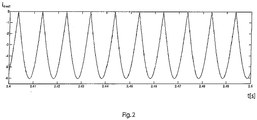
- control 5 is used to adjust the amplitude I A (as in the Figure 2 shown) and adjust the phase position of the id current with respect to the AC mains voltage U N , the generated pulsating electrical energy being stored as magnetic energy in the EC motor 1 by regulating the id current component by means of the primary control 4.
- the undesired pulsation of the motor torque caused by the pulsation of the direct voltage, as a result of a deliberately undersized capacitor capacity, can be compensated for by the controller 4, 5 of the id current.
- the id current curve required for this is shown in the Figure 2 can be seen, with only negative current pulses being generated.
Landscapes
- Engineering & Computer Science (AREA)
- Power Engineering (AREA)
- Control Of Motors That Do Not Use Commutators (AREA)
- Rectifiers (AREA)
- Control Of Ac Motors In General (AREA)
Claims (9)
- Procédé permettant de réduire l'ondulation du couple et l'émission de bruit d'un moteur EC (1) à alimentation monophasée avec un stockage intermédiaire d'énergie électrique dans le moteur EC (1) qui est réalisé avec un circuit de correction de facteur de puissance (PFC), présentant un condensateur (3), à l'entrée de réseau pour une tension alternative de réseau UN déterminée, la capacité du condensateur (CZ) étant dimensionnée de telle sorte que lorsque la tension alternative de réseau UN est appliquée, une tension continue puisée est produite dans un circuit intermédiaire (Z), l'énergie électrique pulsée ainsi produite étant stockée, par une régulation primaire (4) de la part de courant id, sous forme d'énergie magnétique dans le moteur EC (1) au moins pendant une période prédéfinie, caractérisé en ce que pour la commande du courant id, une régulation non linéaire, basée sur la platitude et commandée par des trajectoires, est utilisée dans l'espace d'états.
- Procédé selon la revendication 1, caractérisé en ce que la commande (4) destinée au stockage de l'énergie comprend l'adaptation de la part de courant id formant le champ.
- Procédé selon la revendication 1 ou 2, caractérisé en ce que la fréquence de la trajectoire de courant id correspond au double de la fréquence de réseau de la fréquence alternative de réseau UN et est synchronisée avec la fréquence de réseau.
- Procédé selon l'une quelconque des revendications précédentes, caractérisé en ce que l'amplitude et la position de phase du courant id par rapport à la tension alternative de réseau UN est réglée par une deuxième spécification de valeur de consigne id superposée à la régulation primaire de telle sorte que la pulsation de la tension continue produite dans le circuit intermédiaire (Z) est réduite ou minimisée.
- Procédé selon la revendication 4, caractérisé en ce que l'amplitude du courant id est choisie pour être aussi faible que possible lors de la régulation dans le champ de régulation amplitude/position de phase potentiel.
- Procédé selon l'une quelconque des revendications précédentes, caractérisé en ce que l'amplitude du courant id est appliquée de manière négative afin d'assurer par l'affaiblissement de champ ainsi obtenu une réduction des pertes dans le fer dans le moteur EC (1).
- Moteur EC (1) à alimentation monophasée, comprenant un ensemble de circuits (1a) doté d'un circuit intermédiaire (Z) comprenant :a. une entrée de réseau (2) pour la connexion à au moins une tension alternative de réseau UN déterminée,b. un circuit de correction de facteur de puissance (PFC) côté entrée de réseau, doté d'un condensateur (CZ), la capacité du condensateur (Ca) étant dimensionnée de telle sorte que lorsqu'une tension alternative de réseau UN est appliquée, une tension continue pulsée UZK est produite dans le circuit intermédiaire (Z),
caractérisé parc. un dispositif de régulation primaire (4) comprenant une planification de trajectoire (TP) et un régulateur d'état basé sur la platitude (FZ) pour réguler la part de courant id de telle sorte que l'énergie électrique pulsée peut être stockée sous forme d'énergie magnétique dans le moteur EC (1) au moins pendant une période prédéfinie. - Moteur EC (1) selon la revendication 7, caractérisé en ce qu'une deuxième régulation (5) est prévue pour régler l'amplitude (lA) et la position de phase du courant id par rapport à la tension alternative de réseau UN.
- Moteur EC (1) selon la revendication 8, caractérisé en ce que la deuxième régulation (5) pour l'adaptation de la position de phase et de l'amplitude du courant id est réalisée de telle sorte que la pulsation d'une tension continue produite dans le circuit intermédiaire (Z) est réduite ou minimisée par celle-ci.
Applications Claiming Priority (2)
| Application Number | Priority Date | Filing Date | Title |
|---|---|---|---|
| DE102017126150.8A DE102017126150A1 (de) | 2017-11-08 | 2017-11-08 | Kapazitätsreduzierung |
| PCT/EP2018/080395 WO2019091996A1 (fr) | 2017-11-08 | 2018-11-07 | Réduction de capacité |
Publications (2)
| Publication Number | Publication Date |
|---|---|
| EP3610570A1 EP3610570A1 (fr) | 2020-02-19 |
| EP3610570B1 true EP3610570B1 (fr) | 2021-11-03 |
Family
ID=64184091
Family Applications (1)
| Application Number | Title | Priority Date | Filing Date |
|---|---|---|---|
| EP18799749.9A Active EP3610570B1 (fr) | 2017-11-08 | 2018-11-07 | Réduction de capacité |
Country Status (5)
| Country | Link |
|---|---|
| US (1) | US11362603B2 (fr) |
| EP (1) | EP3610570B1 (fr) |
| CN (1) | CN208508827U (fr) |
| DE (1) | DE102017126150A1 (fr) |
| WO (1) | WO2019091996A1 (fr) |
Cited By (1)
| Publication number | Priority date | Publication date | Assignee | Title |
|---|---|---|---|---|
| EP4734356A1 (fr) | 2024-10-24 | 2026-04-29 | ebm-papst Mulfingen GmbH & Co. KGaA & Co. KG | Dispositif et procédé de fonctionnement d'un moteur électrique ainsi que système comprenant le dispositif et le moteur électrique |
Families Citing this family (5)
| Publication number | Priority date | Publication date | Assignee | Title |
|---|---|---|---|---|
| DE102019204576B4 (de) * | 2019-04-01 | 2021-03-11 | Robert Bosch Gmbh | Verfahren zur Reduktion von Drehmomentschwankungen einer elektrischen Drehstrommaschine eines Lenksystems |
| DE102019206872A1 (de) | 2019-05-13 | 2020-11-19 | Rolls-Royce Deutschland Ltd & Co Kg | Minimalistischer Stromrichter und Fahrzeug mit einem Stromrichter |
| US12399483B2 (en) * | 2019-10-21 | 2025-08-26 | Semiconductor Components Industries, Llc | Systems and methods for system optimization and/or failure detection |
| ES2972062T3 (es) * | 2020-04-01 | 2024-06-11 | Siemens Ag | Dispositivo de control para un convertidor de circuito intermedio y un convertidor de circuito intermedio |
| DE102023131705A1 (de) | 2023-11-14 | 2025-05-15 | Ebm-Papst Mulfingen Gmbh & Co. Kg | Mehrmotorenumrichter |
Citations (2)
| Publication number | Priority date | Publication date | Assignee | Title |
|---|---|---|---|---|
| DE19834315A1 (de) * | 1998-07-30 | 2000-02-03 | Ako Werke Gmbh & Co | Schaltungsanordnung zur Messung und Begrenzung von Strömen in Umrichtern zur Speisung von Motoren |
| EP2276162B1 (fr) * | 2009-07-17 | 2012-10-03 | ebm-papst Mulfingen GmbH & Co. KG | Procédé et système de commande destinés au fonctionnement d'un moteur électrique sans balais |
Family Cites Families (11)
| Publication number | Priority date | Publication date | Assignee | Title |
|---|---|---|---|---|
| GB2275836B (en) | 1993-02-27 | 1997-07-30 | Gold Star Co | A switched reluctance motor driving circuit |
| GB9507540D0 (en) | 1995-04-11 | 1995-05-31 | Switched Reluctance Drives Ltd | Control circuit and system for a switched reluctance machine and method of operating |
| GB9608216D0 (en) | 1996-04-19 | 1996-06-26 | Switched Reluctance Drives Ltd | Converter circuit for a polyphase switched inductive load |
| US5994869A (en) * | 1997-12-05 | 1999-11-30 | General Electric Company | Power conversion circuit for a motor |
| US7495410B2 (en) * | 2007-01-30 | 2009-02-24 | Rockwell Automation Technologies, Inc. | Systems and methods for improved motor drive power factor control |
| US8698433B2 (en) * | 2009-08-10 | 2014-04-15 | Emerson Climate Technologies, Inc. | Controller and method for minimizing phase advance current |
| JP5337663B2 (ja) * | 2009-10-15 | 2013-11-06 | 株式会社東芝 | ドライバ回路 |
| JP5212491B2 (ja) * | 2011-01-18 | 2013-06-19 | ダイキン工業株式会社 | 電力変換装置 |
| EP2482442B2 (fr) * | 2011-01-27 | 2021-02-24 | ebm-papst Mulfingen GmbH & Co. KG | Procédé et système de commande destinés au fonctionnement d'un moteur électrique sans balais |
| DE102012010092A1 (de) * | 2011-05-30 | 2012-12-06 | Secop Gmbh | Regler und Verfahren zur Regelung eines Motors für einen Verdichter |
| US9914362B2 (en) * | 2013-04-15 | 2018-03-13 | Virginia Tech Intellectual Properties, Inc. | Energy storage for power factor correction in battery charger for electric-powered vehicles |
-
2017
- 2017-11-08 DE DE102017126150.8A patent/DE102017126150A1/de not_active Withdrawn
- 2017-12-19 CN CN201721781056.0U patent/CN208508827U/zh active Active
-
2018
- 2018-11-07 EP EP18799749.9A patent/EP3610570B1/fr active Active
- 2018-11-07 WO PCT/EP2018/080395 patent/WO2019091996A1/fr not_active Ceased
- 2018-11-07 US US16/762,848 patent/US11362603B2/en active Active
Patent Citations (3)
| Publication number | Priority date | Publication date | Assignee | Title |
|---|---|---|---|---|
| DE19834315A1 (de) * | 1998-07-30 | 2000-02-03 | Ako Werke Gmbh & Co | Schaltungsanordnung zur Messung und Begrenzung von Strömen in Umrichtern zur Speisung von Motoren |
| EP0977337B1 (fr) * | 1998-07-30 | 2011-03-09 | Diehl AKO Stiftung & Co. KG | Circuit de mesure et de limitation des courants dans des convertisseurs pour l'alimentation des moteurs |
| EP2276162B1 (fr) * | 2009-07-17 | 2012-10-03 | ebm-papst Mulfingen GmbH & Co. KG | Procédé et système de commande destinés au fonctionnement d'un moteur électrique sans balais |
Cited By (2)
| Publication number | Priority date | Publication date | Assignee | Title |
|---|---|---|---|---|
| EP4734356A1 (fr) | 2024-10-24 | 2026-04-29 | ebm-papst Mulfingen GmbH & Co. KGaA & Co. KG | Dispositif et procédé de fonctionnement d'un moteur électrique ainsi que système comprenant le dispositif et le moteur électrique |
| DE102024130971A1 (de) | 2024-10-24 | 2026-04-30 | ebm-papst Mulfingen GmbH & Co. KGaA & Co. KG | Vorrichtung und Verfahren zum Betreiben eines Elektromotors sowie System aufweisend die Vorrichtung und den Elektromotor |
Also Published As
| Publication number | Publication date |
|---|---|
| US11362603B2 (en) | 2022-06-14 |
| US20200287483A1 (en) | 2020-09-10 |
| DE102017126150A1 (de) | 2019-05-09 |
| CN208508827U (zh) | 2019-02-15 |
| WO2019091996A1 (fr) | 2019-05-16 |
| EP3610570A1 (fr) | 2020-02-19 |
Similar Documents
| Publication | Publication Date | Title |
|---|---|---|
| EP3610570B1 (fr) | Réduction de capacité | |
| EP2276162B1 (fr) | Procédé et système de commande destinés au fonctionnement d'un moteur électrique sans balais | |
| EP2979352B1 (fr) | Dispositif, en particulier machine ou installation, et procédé permettant de faire fonctionner un dispositif | |
| DE202017106787U1 (de) | Vorrichtung zur Kapazitätsreduzierung | |
| EP3642932A1 (fr) | Dispositif et procédé pour générer et injecter activement de la puissance réactive dans un système de transmission inductif | |
| CH714180B1 (de) | Konverter zur Übertragung von elektrischer Energie zwischen einem DC und einem AC-System. | |
| EP2856625B1 (fr) | Alimentation en tension pour un onduleur | |
| DE19531210A1 (de) | Steuersystem für einphasigen PWM-Wandler | |
| DE2434316A1 (de) | Statische leistungsumformungseinrichtung | |
| WO2013113540A2 (fr) | Commande sélective d'un moteur à courant alternatif ou d'un moteur à courant continu | |
| DE112018008052B4 (de) | Leistungswandlersystem | |
| WO2017050960A1 (fr) | Procédé de fonctionnement d'un convertisseur de courant modulaire à multiples niveaux, convertisseur de courant modulaire à multiples niveaux ainsi que programme d'ordinateur | |
| EP3043461B1 (fr) | Circuit d'alimentation d'un appareil de soudage | |
| WO2023066952A1 (fr) | Procédé de régulation d'un convertisseur résonnant | |
| EP1619781B1 (fr) | Circuit pour un convertisseur | |
| DE10044574A1 (de) | Schaltungsanordnung zum variablen Steuern von Wechselstromverbrauchern | |
| WO2010088979A1 (fr) | Procédé de régulation d'un convertisseur côté réseau à commutation automatique dans un convertisseur indirect de tension | |
| DE102012207263B4 (de) | Versorgungsstrang, Versorgungssystem und Verfahren zum Betreiben eines elektrischen Antriebs | |
| EP2778426B1 (fr) | Moteur électrique doté d'un système de convertisseur électronique de puissance et dispositif de refroidissement actif alimenté à partir de celui-ci | |
| EP2975747B1 (fr) | Amélioration d'une tension d'une liaison d'alimentation en courant | |
| WO2005114830A1 (fr) | Dispositif convertisseur de frequence pour parc a energie eolienne et procede pour exploiter un tel dispositif | |
| DE20023570U1 (de) | Gargerät mit Spannungs-, Phasen- und/oder Frequenzumwandler | |
| EP2677622A2 (fr) | Procédé et dispositif d'injection d'une puissance électrique dans un réseau d'alimentation en énergie électrique | |
| DE112024002495T5 (de) | Wechselstrom-Gleichstrom-Wandler, Drehmaschinenantrieb und Kühlkreislauf-Anwendungsgerät | |
| EP4734356A1 (fr) | Dispositif et procédé de fonctionnement d'un moteur électrique ainsi que système comprenant le dispositif et le moteur électrique |
Legal Events
| Date | Code | Title | Description |
|---|---|---|---|
| STAA | Information on the status of an ep patent application or granted ep patent |
Free format text: STATUS: UNKNOWN |
|
| STAA | Information on the status of an ep patent application or granted ep patent |
Free format text: STATUS: THE INTERNATIONAL PUBLICATION HAS BEEN MADE |
|
| PUAI | Public reference made under article 153(3) epc to a published international application that has entered the european phase |
Free format text: ORIGINAL CODE: 0009012 |
|
| STAA | Information on the status of an ep patent application or granted ep patent |
Free format text: STATUS: REQUEST FOR EXAMINATION WAS MADE |
|
| 17P | Request for examination filed |
Effective date: 20191115 |
|
| AK | Designated contracting states |
Kind code of ref document: A1 Designated state(s): AL AT BE BG CH CY CZ DE DK EE ES FI FR GB GR HR HU IE IS IT LI LT LU LV MC MK MT NL NO PL PT RO RS SE SI SK SM TR |
|
| AX | Request for extension of the european patent |
Extension state: BA ME |
|
| DAV | Request for validation of the european patent (deleted) | ||
| DAX | Request for extension of the european patent (deleted) | ||
| REG | Reference to a national code |
Ref country code: DE Ref legal event code: R079 Ref document number: 502018007709 Country of ref document: DE Free format text: PREVIOUS MAIN CLASS: H02P0006260000 Ipc: H02P0021050000 |
|
| GRAP | Despatch of communication of intention to grant a patent |
Free format text: ORIGINAL CODE: EPIDOSNIGR1 |
|
| STAA | Information on the status of an ep patent application or granted ep patent |
Free format text: STATUS: GRANT OF PATENT IS INTENDED |
|
| RIC1 | Information provided on ipc code assigned before grant |
Ipc: H02P 6/10 20060101ALI20210426BHEP Ipc: H02P 21/05 20060101AFI20210426BHEP |
|
| INTG | Intention to grant announced |
Effective date: 20210531 |
|
| GRAJ | Information related to disapproval of communication of intention to grant by the applicant or resumption of examination proceedings by the epo deleted |
Free format text: ORIGINAL CODE: EPIDOSDIGR1 |
|
| STAA | Information on the status of an ep patent application or granted ep patent |
Free format text: STATUS: REQUEST FOR EXAMINATION WAS MADE |
|
| GRAP | Despatch of communication of intention to grant a patent |
Free format text: ORIGINAL CODE: EPIDOSNIGR1 |
|
| STAA | Information on the status of an ep patent application or granted ep patent |
Free format text: STATUS: GRANT OF PATENT IS INTENDED |
|
| GRAS | Grant fee paid |
Free format text: ORIGINAL CODE: EPIDOSNIGR3 |
|
| GRAA | (expected) grant |
Free format text: ORIGINAL CODE: 0009210 |
|
| STAA | Information on the status of an ep patent application or granted ep patent |
Free format text: STATUS: THE PATENT HAS BEEN GRANTED |
|
| INTC | Intention to grant announced (deleted) | ||
| INTG | Intention to grant announced |
Effective date: 20210916 |
|
| AK | Designated contracting states |
Kind code of ref document: B1 Designated state(s): AL AT BE BG CH CY CZ DE DK EE ES FI FR GB GR HR HU IE IS IT LI LT LU LV MC MK MT NL NO PL PT RO RS SE SI SK SM TR |
|
| REG | Reference to a national code |
Ref country code: GB Ref legal event code: FG4D Free format text: NOT ENGLISH |
|
| REG | Reference to a national code |
Ref country code: AT Ref legal event code: REF Ref document number: 1444895 Country of ref document: AT Kind code of ref document: T Effective date: 20211115 Ref country code: CH Ref legal event code: EP |
|
| REG | Reference to a national code |
Ref country code: DE Ref legal event code: R096 Ref document number: 502018007709 Country of ref document: DE |
|
| REG | Reference to a national code |
Ref country code: IE Ref legal event code: FG4D Free format text: LANGUAGE OF EP DOCUMENT: GERMAN |
|
| REG | Reference to a national code |
Ref country code: NL Ref legal event code: FP |
|
| REG | Reference to a national code |
Ref country code: LT Ref legal event code: MG9D |
|
| PG25 | Lapsed in a contracting state [announced via postgrant information from national office to epo] |
Ref country code: RS Free format text: LAPSE BECAUSE OF FAILURE TO SUBMIT A TRANSLATION OF THE DESCRIPTION OR TO PAY THE FEE WITHIN THE PRESCRIBED TIME-LIMIT Effective date: 20211103 Ref country code: LT Free format text: LAPSE BECAUSE OF FAILURE TO SUBMIT A TRANSLATION OF THE DESCRIPTION OR TO PAY THE FEE WITHIN THE PRESCRIBED TIME-LIMIT Effective date: 20211103 Ref country code: FI Free format text: LAPSE BECAUSE OF FAILURE TO SUBMIT A TRANSLATION OF THE DESCRIPTION OR TO PAY THE FEE WITHIN THE PRESCRIBED TIME-LIMIT Effective date: 20211103 Ref country code: BG Free format text: LAPSE BECAUSE OF FAILURE TO SUBMIT A TRANSLATION OF THE DESCRIPTION OR TO PAY THE FEE WITHIN THE PRESCRIBED TIME-LIMIT Effective date: 20220203 |
|
| PG25 | Lapsed in a contracting state [announced via postgrant information from national office to epo] |
Ref country code: IS Free format text: LAPSE BECAUSE OF FAILURE TO SUBMIT A TRANSLATION OF THE DESCRIPTION OR TO PAY THE FEE WITHIN THE PRESCRIBED TIME-LIMIT Effective date: 20220303 Ref country code: SE Free format text: LAPSE BECAUSE OF FAILURE TO SUBMIT A TRANSLATION OF THE DESCRIPTION OR TO PAY THE FEE WITHIN THE PRESCRIBED TIME-LIMIT Effective date: 20211103 Ref country code: PT Free format text: LAPSE BECAUSE OF FAILURE TO SUBMIT A TRANSLATION OF THE DESCRIPTION OR TO PAY THE FEE WITHIN THE PRESCRIBED TIME-LIMIT Effective date: 20220303 Ref country code: PL Free format text: LAPSE BECAUSE OF FAILURE TO SUBMIT A TRANSLATION OF THE DESCRIPTION OR TO PAY THE FEE WITHIN THE PRESCRIBED TIME-LIMIT Effective date: 20211103 Ref country code: NO Free format text: LAPSE BECAUSE OF FAILURE TO SUBMIT A TRANSLATION OF THE DESCRIPTION OR TO PAY THE FEE WITHIN THE PRESCRIBED TIME-LIMIT Effective date: 20220203 Ref country code: LV Free format text: LAPSE BECAUSE OF FAILURE TO SUBMIT A TRANSLATION OF THE DESCRIPTION OR TO PAY THE FEE WITHIN THE PRESCRIBED TIME-LIMIT Effective date: 20211103 Ref country code: HR Free format text: LAPSE BECAUSE OF FAILURE TO SUBMIT A TRANSLATION OF THE DESCRIPTION OR TO PAY THE FEE WITHIN THE PRESCRIBED TIME-LIMIT Effective date: 20211103 Ref country code: GR Free format text: LAPSE BECAUSE OF FAILURE TO SUBMIT A TRANSLATION OF THE DESCRIPTION OR TO PAY THE FEE WITHIN THE PRESCRIBED TIME-LIMIT Effective date: 20220204 Ref country code: ES Free format text: LAPSE BECAUSE OF FAILURE TO SUBMIT A TRANSLATION OF THE DESCRIPTION OR TO PAY THE FEE WITHIN THE PRESCRIBED TIME-LIMIT Effective date: 20211103 |
|
| REG | Reference to a national code |
Ref country code: CH Ref legal event code: PL |
|
| PG25 | Lapsed in a contracting state [announced via postgrant information from national office to epo] |
Ref country code: SM Free format text: LAPSE BECAUSE OF FAILURE TO SUBMIT A TRANSLATION OF THE DESCRIPTION OR TO PAY THE FEE WITHIN THE PRESCRIBED TIME-LIMIT Effective date: 20211103 Ref country code: SK Free format text: LAPSE BECAUSE OF FAILURE TO SUBMIT A TRANSLATION OF THE DESCRIPTION OR TO PAY THE FEE WITHIN THE PRESCRIBED TIME-LIMIT Effective date: 20211103 Ref country code: RO Free format text: LAPSE BECAUSE OF FAILURE TO SUBMIT A TRANSLATION OF THE DESCRIPTION OR TO PAY THE FEE WITHIN THE PRESCRIBED TIME-LIMIT Effective date: 20211103 Ref country code: LU Free format text: LAPSE BECAUSE OF NON-PAYMENT OF DUE FEES Effective date: 20211107 Ref country code: EE Free format text: LAPSE BECAUSE OF FAILURE TO SUBMIT A TRANSLATION OF THE DESCRIPTION OR TO PAY THE FEE WITHIN THE PRESCRIBED TIME-LIMIT Effective date: 20211103 Ref country code: DK Free format text: LAPSE BECAUSE OF FAILURE TO SUBMIT A TRANSLATION OF THE DESCRIPTION OR TO PAY THE FEE WITHIN THE PRESCRIBED TIME-LIMIT Effective date: 20211103 Ref country code: CZ Free format text: LAPSE BECAUSE OF FAILURE TO SUBMIT A TRANSLATION OF THE DESCRIPTION OR TO PAY THE FEE WITHIN THE PRESCRIBED TIME-LIMIT Effective date: 20211103 Ref country code: BE Free format text: LAPSE BECAUSE OF NON-PAYMENT OF DUE FEES Effective date: 20211130 |
|
| REG | Reference to a national code |
Ref country code: BE Ref legal event code: MM Effective date: 20211130 |
|
| REG | Reference to a national code |
Ref country code: DE Ref legal event code: R097 Ref document number: 502018007709 Country of ref document: DE |
|
| PG25 | Lapsed in a contracting state [announced via postgrant information from national office to epo] |
Ref country code: MC Free format text: LAPSE BECAUSE OF FAILURE TO SUBMIT A TRANSLATION OF THE DESCRIPTION OR TO PAY THE FEE WITHIN THE PRESCRIBED TIME-LIMIT Effective date: 20211103 Ref country code: LI Free format text: LAPSE BECAUSE OF NON-PAYMENT OF DUE FEES Effective date: 20211130 Ref country code: CH Free format text: LAPSE BECAUSE OF NON-PAYMENT OF DUE FEES Effective date: 20211130 |
|
| PLBE | No opposition filed within time limit |
Free format text: ORIGINAL CODE: 0009261 |
|
| STAA | Information on the status of an ep patent application or granted ep patent |
Free format text: STATUS: NO OPPOSITION FILED WITHIN TIME LIMIT |
|
| 26N | No opposition filed |
Effective date: 20220804 |
|
| PG25 | Lapsed in a contracting state [announced via postgrant information from national office to epo] |
Ref country code: IE Free format text: LAPSE BECAUSE OF NON-PAYMENT OF DUE FEES Effective date: 20211107 Ref country code: AL Free format text: LAPSE BECAUSE OF FAILURE TO SUBMIT A TRANSLATION OF THE DESCRIPTION OR TO PAY THE FEE WITHIN THE PRESCRIBED TIME-LIMIT Effective date: 20211103 |
|
| PG25 | Lapsed in a contracting state [announced via postgrant information from national office to epo] |
Ref country code: SI Free format text: LAPSE BECAUSE OF FAILURE TO SUBMIT A TRANSLATION OF THE DESCRIPTION OR TO PAY THE FEE WITHIN THE PRESCRIBED TIME-LIMIT Effective date: 20211103 |
|
| P01 | Opt-out of the competence of the unified patent court (upc) registered |
Effective date: 20230522 |
|
| PG25 | Lapsed in a contracting state [announced via postgrant information from national office to epo] |
Ref country code: CY Free format text: LAPSE BECAUSE OF FAILURE TO SUBMIT A TRANSLATION OF THE DESCRIPTION OR TO PAY THE FEE WITHIN THE PRESCRIBED TIME-LIMIT Effective date: 20211103 |
|
| PG25 | Lapsed in a contracting state [announced via postgrant information from national office to epo] |
Ref country code: HU Free format text: LAPSE BECAUSE OF FAILURE TO SUBMIT A TRANSLATION OF THE DESCRIPTION OR TO PAY THE FEE WITHIN THE PRESCRIBED TIME-LIMIT; INVALID AB INITIO Effective date: 20181107 |
|
| PG25 | Lapsed in a contracting state [announced via postgrant information from national office to epo] |
Ref country code: MK Free format text: LAPSE BECAUSE OF FAILURE TO SUBMIT A TRANSLATION OF THE DESCRIPTION OR TO PAY THE FEE WITHIN THE PRESCRIBED TIME-LIMIT Effective date: 20211103 |
|
| PG25 | Lapsed in a contracting state [announced via postgrant information from national office to epo] |
Ref country code: MT Free format text: LAPSE BECAUSE OF FAILURE TO SUBMIT A TRANSLATION OF THE DESCRIPTION OR TO PAY THE FEE WITHIN THE PRESCRIBED TIME-LIMIT Effective date: 20211103 |
|
| PG25 | Lapsed in a contracting state [announced via postgrant information from national office to epo] |
Ref country code: TR Free format text: LAPSE BECAUSE OF FAILURE TO SUBMIT A TRANSLATION OF THE DESCRIPTION OR TO PAY THE FEE WITHIN THE PRESCRIBED TIME-LIMIT Effective date: 20211103 |
|
| PGFP | Annual fee paid to national office [announced via postgrant information from national office to epo] |
Ref country code: NL Payment date: 20251119 Year of fee payment: 8 |
|
| PGFP | Annual fee paid to national office [announced via postgrant information from national office to epo] |
Ref country code: DE Payment date: 20251118 Year of fee payment: 8 |
|
| PGFP | Annual fee paid to national office [announced via postgrant information from national office to epo] |
Ref country code: GB Payment date: 20251120 Year of fee payment: 8 |
|
| PGFP | Annual fee paid to national office [announced via postgrant information from national office to epo] |
Ref country code: AT Payment date: 20251117 Year of fee payment: 8 |
|
| PGFP | Annual fee paid to national office [announced via postgrant information from national office to epo] |
Ref country code: IT Payment date: 20251128 Year of fee payment: 8 |
|
| PGFP | Annual fee paid to national office [announced via postgrant information from national office to epo] |
Ref country code: FR Payment date: 20251125 Year of fee payment: 8 |