EP3610823B1 - Steuersystem mit entfernbarem sterilisierbarem knopf - Google Patents
Steuersystem mit entfernbarem sterilisierbarem knopf Download PDFInfo
- Publication number
- EP3610823B1 EP3610823B1 EP18188657.3A EP18188657A EP3610823B1 EP 3610823 B1 EP3610823 B1 EP 3610823B1 EP 18188657 A EP18188657 A EP 18188657A EP 3610823 B1 EP3610823 B1 EP 3610823B1
- Authority
- EP
- European Patent Office
- Prior art keywords
- button
- sterilizable
- removable
- control
- control system
- Prior art date
- Legal status (The legal status is an assumption and is not a legal conclusion. Google has not performed a legal analysis and makes no representation as to the accuracy of the status listed.)
- Active
Links
Images



Classifications
-
- A—HUMAN NECESSITIES
- A61—MEDICAL OR VETERINARY SCIENCE; HYGIENE
- A61C—DENTISTRY; APPARATUS OR METHODS FOR ORAL OR DENTAL HYGIENE
- A61C19/00—Dental auxiliary appliances
- A61C19/06—Implements for therapeutic treatment
-
- A—HUMAN NECESSITIES
- A61—MEDICAL OR VETERINARY SCIENCE; HYGIENE
- A61B—DIAGNOSIS; SURGERY; IDENTIFICATION
- A61B17/00—Surgical instruments, devices or methods
- A61B17/16—Instruments for performing osteoclasis; Drills or chisels for bones; Trepans
- A61B17/1613—Component parts
- A61B17/1626—Control means; Display units
-
- A—HUMAN NECESSITIES
- A61—MEDICAL OR VETERINARY SCIENCE; HYGIENE
- A61C—DENTISTRY; APPARATUS OR METHODS FOR ORAL OR DENTAL HYGIENE
- A61C1/00—Dental machines for boring or cutting ; General features of dental machines or apparatus, e.g. hand-piece design
- A61C1/0007—Control devices or systems
- A61C1/0015—Electrical systems
-
- A—HUMAN NECESSITIES
- A61—MEDICAL OR VETERINARY SCIENCE; HYGIENE
- A61L—METHODS OR APPARATUS FOR STERILISING MATERIALS OR OBJECTS IN GENERAL; DISINFECTION, STERILISATION OR DEODORISATION OF AIR; CHEMICAL ASPECTS OF BANDAGES, DRESSINGS, ABSORBENT PADS OR SURGICAL ARTICLES; MATERIALS FOR BANDAGES, DRESSINGS, ABSORBENT PADS OR SURGICAL ARTICLES
- A61L2/00—Disinfection or sterilisation of materials or objects, in general; Accessories therefor
- A61L2/26—Accessories
-
- E—FIXED CONSTRUCTIONS
- E05—LOCKS; KEYS; WINDOW OR DOOR FITTINGS; SAFES
- E05B—LOCKS; ACCESSORIES THEREFOR; HANDCUFFS
- E05B1/00—Knobs or handles for wings; Knobs, handles, or press buttons for locks or latches on wings
- E05B1/0069—Sanitary doorknobs or handles, e.g. comprising a disinfectant
-
- G—PHYSICS
- G05—CONTROLLING; REGULATING
- G05G—CONTROL DEVICES OR SYSTEMS INSOFAR AS CHARACTERISED BY MECHANICAL FEATURES ONLY
- G05G1/00—Controlling members, e.g. knobs or handles; Assemblies or arrangements thereof; Indicating position of controlling members
- G05G1/04—Controlling members for hand actuation by pivoting movement, e.g. levers
-
- G—PHYSICS
- G06—COMPUTING OR CALCULATING; COUNTING
- G06F—ELECTRIC DIGITAL DATA PROCESSING
- G06F3/00—Input arrangements for transferring data to be processed into a form capable of being handled by the computer; Output arrangements for transferring data from processing unit to output unit, e.g. interface arrangements
- G06F3/01—Input arrangements or combined input and output arrangements for interaction between user and computer
- G06F3/03—Arrangements for converting the position or the displacement of a member into a coded form
- G06F3/033—Pointing devices displaced or positioned by the user, e.g. mice, trackballs, pens or joysticks; Accessories therefor
-
- G—PHYSICS
- G06—COMPUTING OR CALCULATING; COUNTING
- G06F—ELECTRIC DIGITAL DATA PROCESSING
- G06F3/00—Input arrangements for transferring data to be processed into a form capable of being handled by the computer; Output arrangements for transferring data from processing unit to output unit, e.g. interface arrangements
- G06F3/01—Input arrangements or combined input and output arrangements for interaction between user and computer
- G06F3/03—Arrangements for converting the position or the displacement of a member into a coded form
- G06F3/041—Digitisers, e.g. for touch screens or touch pads, characterised by the transducing means
- G06F3/044—Digitisers, e.g. for touch screens or touch pads, characterised by the transducing means by capacitive means
-
- A—HUMAN NECESSITIES
- A61—MEDICAL OR VETERINARY SCIENCE; HYGIENE
- A61B—DIAGNOSIS; SURGERY; IDENTIFICATION
- A61B17/00—Surgical instruments, devices or methods
- A61B2017/00017—Electrical control of surgical instruments
-
- A—HUMAN NECESSITIES
- A61—MEDICAL OR VETERINARY SCIENCE; HYGIENE
- A61B—DIAGNOSIS; SURGERY; IDENTIFICATION
- A61B17/00—Surgical instruments, devices or methods
- A61B2017/00367—Details of actuation of instruments, e.g. relations between pushing buttons, or the like, and activation of the tool, working tip, or the like
- A61B2017/00389—Button or wheel for performing multiple functions, e.g. rotation of shaft and end effector
-
- A—HUMAN NECESSITIES
- A61—MEDICAL OR VETERINARY SCIENCE; HYGIENE
- A61B—DIAGNOSIS; SURGERY; IDENTIFICATION
- A61B17/00—Surgical instruments, devices or methods
- A61B2017/00477—Coupling
-
- A—HUMAN NECESSITIES
- A61—MEDICAL OR VETERINARY SCIENCE; HYGIENE
- A61B—DIAGNOSIS; SURGERY; IDENTIFICATION
- A61B17/00—Surgical instruments, devices or methods
- A61B2017/00831—Material properties
- A61B2017/00876—Material properties magnetic
-
- A—HUMAN NECESSITIES
- A61—MEDICAL OR VETERINARY SCIENCE; HYGIENE
- A61B—DIAGNOSIS; SURGERY; IDENTIFICATION
- A61B90/00—Instruments, implements or accessories specially adapted for surgery or diagnosis and not covered by any of the groups A61B1/00 - A61B50/00, e.g. for luxation treatment or for protecting wound edges
- A61B90/08—Accessories or related features not otherwise provided for
- A61B2090/0813—Accessories designed for easy sterilising, i.e. re-usable
Definitions
- the present invention relates to the field of instruments and devices for practitioners in the medical sector, such as dentists and dental surgeons. More precisely, it relates to a control device for the motor of such devices.
- Dentists, hygienists and dental surgeons, as well as other practitioners in the sector in particular endodontics, periodontology or oral surgery or implantology often use various instruments and devices equipped with a rotating tool operated by a electric motor (micromotor). These motors have a predefined power, which is adapted to the operations to be carried out. For example, depending on the applications (cleaning, polishing, root treatment, etc.), grinding or milling operations require the application of different speeds and different torques adapted to the contact force exerted on the tool to manage effectively the level of abrasion or drilling without generating excessive overheating of the tool which could damage the surrounding tissues.
- control unit To control the micromotors of such tools, different control units are available in the market.
- the applicant's Optima control station makes it possible, for example, to carry out prophylactic or restorative interventions by providing an alternative to turbines, usually used for this type of operations, but which has the disadvantage of being much noisier due to the very high rotation speed (greater than 100,000 revolutions per minute) of the tool driven by pneumatic means.
- Speed control is carried out using a central wheel placed on the front of the console, provided specifically and only for this purpose.
- control units In the field of implantology and maxillofacial surgery, other types of control units are also known, such as the applicant's Chiropro console, which is provided with a control screen as well as several keys. commands arranged on a substantially flat keyboard. The different operating modes are selected using arrows and activated using a central validation key.
- a first disadvantage of this type of console is linked to the relatively non-ergonomic nature of the control interface, often requiring multiple successive presses on the different buttons to change programs.
- a second disadvantage of this type of control unit is linked to the process of disinfection and decontamination of the console keyboard, which during each operation is likely to be completely contaminated following the various manipulations carried out by the surgeon.
- the aim of the invention is to provide a control system provided with a simple interface, practical to use, and easy to sterilize if necessary.
- a control system for a micromotor for dental or surgical use comprising a control box provided with an adjustment wheel rotatably mounted around an axis of rotation, characterized in that the wheel adjustment is formed of a rotary control support around said axis of rotation (AA) and secured to an encoder integrated into the housing, and a sterilizable button coupled magnetically removably to the control support, that is to say in order to allow manual assembly and disassembly of said sterilizable button without the use of tools.
- the adjustment wheel it is possible to easily assemble and disassemble the part handled by the surgeon and sterilize the latter independently of the rest of the control box.
- the sterilizable part can now be considered as a wearing part that can be replaced in a modular manner independently of the rest of the control system, and the latter can therefore be sterilized and washed with more effective, more aggressive chemicals.
- the coupling is carried out magnetically, which allows manual assembly and disassembly of the removable sterilizable button, that is to say without the aid of any auxiliary tool.
- the ease of use is thus greatly improved for this type of assembly and replacement operations of the removable sterilizable part.
- the adjustment wheel is provided both for rotational selection and for actuation by pressure of functions, which can be viewed on a control screen of the housing, which makes it possible to reinforce the level of ergonomics compared to existing products, in which these two functionalities were until now achieved using separate actuation elements.
- the removable sterilizable button is terminated, at its lower end, by a collar extending radially outwards, which has the advantage, on the one hand, of avoiding any contamination accidental damage to the housing when handling the adjustment wheel, and on the other hand, to facilitate the dismantling of the removable sterilizable button by increasing the diameter of the object at the level of the gripping area and thus facilitates manual gripping. Furthermore, in the event that pressure is necessary on the wheel, this can also be carried out more easily by pressing the fingers on the exterior surface of the collar.
- the removable sterilizable button is preferably coupled to the control support so that, in the assembled position, an operating clearance of at least 0.2mm remains axially between the lower end of the sterilizable button and the external surface of the housing when it is at rest, that is to say in the non-pressed position.
- the fingers can pass slightly behind the button to easily grasp it and extract it from the housing during a disassembly operation.
- the removable sterilizable button has a central cavity provided with at least a first interior contact surface for coupling to a support surface and axial retaining and rotation drive means arranged on either side of the removable sterilizable button and the control support.
- the central cavity of the removable sterilizable button opens onto an interior peripheral shoulder.
- Such an arrangement aims to ensure the regularity of the quality of the coupling between removable sterilizable button to the control support independently of the manufacturing dimensions, which can fluctuate slightly for each of these parts depending on the assembly tolerances.
- the quality of this coupling makes it possible in particular to ensure good systematic transmission of torque to the encoder.
- the removable sterilizable button is magnetically coupled to the control support, an active magnetic part being integrated into the support and a passive magnetic part being integrated into the removable sterilizable button, the intensity of the magnetic force exerted being between 5 and 15 Newton.
- the removable sterilizable button comprises a central cavity, as according to a preferred embodiment previously described, but which also contains a second conical interior contact surface, brought into support, in assembled position of the adjustment wheel, against a lateral mating surface of the control support, and these surfaces have an inclination of 15 degrees relative to the axis of rotation (A-A) of the adjustment wheel.
- A-A axis of rotation
- the active magnetic part integrated in the control support is a first permanent magnet arranged so as to present a magnetization oriented perpendicular to the axis of rotation of the adjustment wheel , and a second permanent magnet is integrated into the removable sterilizable button so as to present a magnetization oriented parallel to the first permanent magnet.
- a force of magnetic attraction be established between the button and the support, but a magnetic torque between the button and the support exerted via the two permanent magnets will naturally orient the button on the support when it is placed.
- the active magnetic part integrated into the support control is a first permanent magnet arranged so as to present a magnetization oriented this time directly along the axis of rotation (AA) of the adjustment wheel, and a second permanent magnet is integrated into the removable sterilizable button so as to present a magnetization also oriented along the axis of rotation (AA) of the adjustment wheel, but in the opposite direction to that of this first permanent magnet.
- Such a configuration of magnets in opposite polarity facing each other makes it possible to establish a repulsive force between the button and the support when they are distant from each other, and to simultaneously ensure a significant magnetic attraction force when the button is brought close to the support, thanks to the deviation of the magnetic field lines caused by the ferromagnetic component (i.e. the passive magnetic part) integrated into the button cover.
- the ferromagnetic component i.e. the passive magnetic part
- the user will simply need to move the button slightly away or tilt it relative to the axis of the support to benefit from a magnetic repulsion force favoring its extraction, this which will make it even more effective to avoid any unintentional contact between the contaminated button and the screen or any other part of the control box.
- the removable sterilizable button can be coupled by friction to the control support thanks to O-ring type seals inserted in lateral coupling grooves arranged either on the removable sterilizable button or the control bracket for the adjustment wheel.
- the removable sterilizable button can be assembled to the control support at using elastically deformable clips, and which are provided with coupling lugs intended to be inserted into hooking grooves.
- Such an arrangement also makes it possible to use the same elements both for axial retention and for rotational drive; such a solution is however subject to creep which does not ensure the long-term quality of the coupling.
- the present invention further relates to a control box as well as a sterilizable button taken independently of each other, because these two products can be sold separately, even if they relate to the same control system proposed.
- FIGS. 1A and 1B represent perspective views of a control system 1 provided with a removable sterilizable button 21 according to a preferred embodiment for the present invention, using a magnetic coupling mode.
- the control system 1 uses a control box 10 which conventionally comprises a control screen 11 provided at the external surface 12 of the control box 10, as well as an adjustment wheel 2, provided with an encoder - no visible in these figures but which is represented later in particular on the Figure 3 - and with which he is You can select modes or preset functions by rotating it in one direction or the other. Then, to validate or respectively activate the modes or functions, light pressure can be exerted on wheel 2.
- the level of ergonomics is significantly improved compared to control systems using dedicated keys or any elements separated for the selection and activation of modes or functions.
- the adjustment wheel 2 does not seem to differ from a usual wheel secured to the control box 10 and permanently fixed thereon; we can also distinguish a collar 22 terminating the wheel 2, or more precisely the sterilizable button 21 removable from it, on the side of the housing.
- This flange 22 extends radially outwards, which makes it easier to grip during selection and activation operations while protecting the exterior surface 12 of the control box 10 from unwanted contact with the fingers.
- the operation of dismantling the removable part of the adjustment wheel 2 is also made easier thanks to the slight increase in diameter which makes it easier to pass the fingers just under the removable sterilizable button 21 to grasp it with a view to detach it from the control box 10.
- FIG. 1B illustrates on the other hand the removable nature of the coupling between the sterilizable button 21 and a control support 20 secured to the housing 10.
- the control support 20 is rotatably mounted vis-à-vis the control box of the control system 1, and constitutes a first part of adjustment wheel 2; the other part being formed by a sterilizable button 21 on which is formed the collar 22 extending radially outwards at its base.
- FIG. 2 shows the removable sterilizable button 21 taken in isolation from the rest of the control system 1, and which can thus also be sold separately.
- This sterilizable button 21 is preferably made up of at least partially of a ferromagnetic material such as magnetizable steel in order to constitute a passive magnetic part 5 intended to cooperate with an active magnetic part 4 such as a magnet placed in the control support 20 of the adjustment wheel 2.
- the shape of the removable sterilizable button 21 corresponds substantially to that of a hat, with a collar 22 extending radially at its base and revealing a central cavity 23 allowing the insertion of the control support 20.
- the central cavity 23 is closed by a bottom comprising a first interior contact surface 23a, preferably planar, and intended to be coupled to a bearing surface 24 of the adjustment support 20, and has a second interior contact surface 23b, preferably conical, on which a lateral mating surface 25 of the adjustment support 20 comes to rest.
- An interior peripheral shoulder 28 is however provided to provide additional space at the entrance to the central cavity 23.
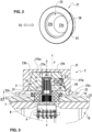
- FIG. 3 explains the mode of coupling between the adjustment support 20 and the removable sterilizable button 21 according to a preferred embodiment of the invention, in which the coupling is magnetic and the lateral surfaces of both the adjustment support 20 and the button removable sterilizable are conical with an inclination between 10 and 20 degrees, and preferably 15 degrees, so as to present an optimal orientation with respect to the field lines generated by the magnet integrated in the control support 20 of the adjustment wheel 2 and whose direction of magnetization is here oriented perpendicular to the axis of rotation AA of the adjustment wheel 2.
- an active magnetic part 4 that is to say the permanent magnet integrated into the control support 20, while the entirety of the removable sterilizable button 21 constitutes a passive magnetic part 5.
- the section of the control support 20 is here trapezoidal, materializing a volume of conical shape truncated at its top.
- the upper part of the trapezoid thus corresponds to the bearing surface 24 of the flat support, which is brought into abutment against the first interior contact surface 23 of the removable sterilizable button 21, constituting the internal face of the cover 210.
- the force of attraction magnetic thus alone constitutes axial retaining means to keep these two surfaces resting against each other.
- the inclination of the second interior contact surface 23b and the lateral coupling surface 25 allows, when the button is rotated by the user, to rotate the encoder 3 integrated into the control support 20 more effectively than with a cooperation of cylindrical surfaces, for which torque transmission is not optimal.
- the encoder 3 is formed here by a threaded rod 31 rotatably mounted along the axis AA of rotation of the adjustment wheel 2 relative to the control box 10, and a screw 32 mounted perpendicular to this axis of rotation AA.
- the cover 210 forming the top of the removable sterilizable button 21, and the axial skirt 211 whose lateral thickness thins as we descend downwards, until reaching the collar 22 oriented radially outwards.
- the external lateral surface 211a of the removable sterilizable button 21 is substantially cylindrical, in order to allow easy gripping of the latter for rotational actuation for selection, typically by means of a drop-down menu.
- the control support 20 will then be driven downwards going against the restoring force F of the spring 8 oriented upwards to make an electrical contact of the resistive type with the electronic control circuit 9.
- the control support 20 will be returned to its rest position under the action of the return force F exerted by the return spring 8.
- the adjustment wheel 2 is mounted in an insertion tube 7 in the housing, which has an upper shoulder 72 partially covering the external surface 12 of the control box 10, and which is affixed to a sealing joint 71.
- an additional volume is however generated above the latter, and which should not prevent the action of pressure on the button - transmitted directly to the control support 20 - until electrical contact is obtained with the control circuit 9.
- the interior peripheral shoulder 28 materialized by the hatched part
- the interior peripheral shoulder 28 is provided at the mouth of the central cavity 23 to provide an additional recess avoiding any potential interference with the upper shoulder 72 of the wheel insertion tube.
- the adjustment wheel 2 is in the depressed position, while the arrow materialized by the reference E defines an operating clearance at rest, that is to say the spacing between the external surface of the housing 12 and the lower surface of the flange 22b.
- This operating clearance is defined as being preferably equal to at least 0.2 millimeters, and can preferably go up to 1 millimeter to easily allow the removable sterilizable button 21 to be grasped and removed after use.
- the removable sterilizable button 21 is magnetically coupled to the control support 20
- only an active magnetic part 4 is integrated in the control support 20
- the removable sterilizable button 21 constitutes an integral passive magnetic part 5, such that the intensity of the magnetic force exerted is preferably between 5 and 15 Newton.
- This range of values relating to the intensity of the magnetic force allows disassembly operations to remain easy without requiring any sudden or violent action to remove the removable sterilizable button 21.
- other variants are possible while always remaining within the framework of a magnetic coupling mode, for example using a removable sterilizable button 21 composed only partially of magnetic material, or even by arranging permanent magnets on both sides. other of the control support 20 and the removable sterilizable button 21, as explained using the diagrams of the figures 4 and 5 that follow.
- FIG. 4 schematically illustrates a preferred variant for a magnetic type coupling mode between the control support 20 and the removable sterilizable button 21, according to which, in addition to a first permanent magnet 4' constituting an active magnetic part 4 arranged similarly to that of there Figure 3 , that is to say with a direction of magnetization orthogonal to the axis of rotation AA of the adjustment wheel 2, a second permanent magnet 4" is arranged in the removable sterilizable button 21 in a direction of magnetization included in a parallel plane, superimposed on that of the first permanent magnet 4'.
- the two permanent magnets 4' and 4" will tend to orient themselves naturally in a direction of magnetization parallel to each other, in due to the preservation of pole alignment following the laws of physics.
- two advantageous technical effects are achieved, the first being to obtain an identical angular indexing position of the removable sterilizable button 21 following each assembly on its control support 20, and the second being to guarantee even better transmission of the torque exerted on the sterilizable button 21 removable to the control support 20 during the rotational actuation of the wheel 2 (indicated by the arrow in the direction of clockwise on the Figure 4 , also showing the direction of the field lines L and the North “N” and South “S” poles of each magnet).
- This coupling variant has the advantage of dispensing, at least partially, but virtually entirely, the removable sterilizable button 21 of any ferromagnetic material to obtain the desired effects in terms of quality of torque transmission and resistance to the control support 20 ; however, here again we will favor, with or without the presence of passive ferromagnetic material, preferably an arrangement of permanent magnets making it possible to obtain an attractive force within the same value ranges as those mentioned previously, namely between 5 and 15 Newtons.
- FIG. 5 illustrates yet another preferred variant using a magnetic coupling mode using two permanent magnets arranged respectively on either side of the control support 20 and the removable sterilizable button 21.
- the first permanent magnet 4' of the control support 20 and the second permanent magnet 4" of the removable sterilizable button are now arranged directly along the axis of rotation AA of the adjustment wheel, and in polarity opposition (the poles North “N” of each of the magnets facing each other).
- Figure 5 when the removable sterilizable button 21 is substantially distant from the control support 20, the field lines L of each of the magnets are directed relative to each other in such a way that a repulsive effect materialized by the arrow is generated between these two parts .
- the magnetic repulsion force transforms into a magnetic attraction force, in view of the spatial reorganization of the field lines L which tends to maximize the magnetic flux through the different components.
- the assembly operation provides a sort of "click effect" as soon as the threshold of mutual proximity between removable sterilizable button 21 and the control support 20 is crossed, transforming the force of magnetic repulsion to a force of magnetic attraction.
- the advantage common to all the preferred variants using a magnetic coupling mode between the removable sterilizable button 21 and the control support 20 is that the assembly and disassembly operations are particularly simple, requiring no tools, and that these operations can be repeated a very large number of times without harming the holding of the removable sterilizable button 21 on the control support 20 nor the transmission of the torque exerted by the user to the encoder 3 of the adjustment wheel 2.
- magnets are inserted in the removable sterilizable button 21, it is possible, using for example magnets made from Samarium Cobalt, to subject the latter to several hundred sterilization cycles at 135°C or more without altering their properties magnetic because their Curie temperature exceeds 300°C.
- the mode of coupling between the removable sterilizable button 21 and the control support 20 can be achieved by friction, for example using one or more O-type coupling joints.
- ring 6 inserted into coupling grooves 29.
- a first coupling groove 29 is arranged just under the cover 210, i.e. in a fairly high portion of the control support 20, and a second coupling groove 29 is arranged at the bottom of the control support, such that the friction forces are distributed over two O-ring seals 6, the compression of which against respective portions of the second interior contact surface 23b of the removable sterilizable button 21 jointly makes it possible to avoid any tearing of the latter and to transmit the torque exerted on him to encoder 3.
- the coupling can be carried out by clipping using at least one elastically deformable clip 26 (on the Figure 7 , we can distinguish 6) and made up for example of a plastic material, having a lug 26a at its end, which is intended to be inserted into a hooking groove 27 arranged in the control support 20.
- the cooperation of the The lug 26a in the hooking groove 27 makes it possible on the one hand to guarantee the axial retention of the removable sterilizable button 21 on the control support 20 to avoid any tearing, and also to guarantee the transmission of torque.
- the magnetic coupling in other ways by, for example, reversing the arrangement of the passive and active magnetic parts respectively in the control support and the removable sterilizable button, or even by arranging a number of permanent magnets different distributed between each of these two pieces to be assembled. It is also possible to use different geometric shapes for the control support 20, as well as for the removable sterilizable button 21, particularly with regard to the axial and lateral coupling bearing surfaces. Similarly, the number of elements provided for hooking & rotational drive (i.e. the tabs or clips 26, the lateral coupling grooves 29 for the placement of the O-rings 6, etc.
Landscapes
- Health & Medical Sciences (AREA)
- Engineering & Computer Science (AREA)
- Life Sciences & Earth Sciences (AREA)
- Public Health (AREA)
- General Engineering & Computer Science (AREA)
- Theoretical Computer Science (AREA)
- General Health & Medical Sciences (AREA)
- Epidemiology (AREA)
- Veterinary Medicine (AREA)
- Animal Behavior & Ethology (AREA)
- General Physics & Mathematics (AREA)
- Physics & Mathematics (AREA)
- Oral & Maxillofacial Surgery (AREA)
- Dentistry (AREA)
- Surgery (AREA)
- Human Computer Interaction (AREA)
- Nuclear Medicine, Radiotherapy & Molecular Imaging (AREA)
- Water Supply & Treatment (AREA)
- Molecular Biology (AREA)
- Medical Informatics (AREA)
- Heart & Thoracic Surgery (AREA)
- Biomedical Technology (AREA)
- Automation & Control Theory (AREA)
- Orthopedic Medicine & Surgery (AREA)
- Dental Tools And Instruments Or Auxiliary Dental Instruments (AREA)
Claims (10)
- Steuersystem (1) für einen Mikromotor für einen zahnmedizinischen oder chirurgischen Einsatz, umfassend eine Steuerbox (10), die mit einem Einstelldrehknopf (2) versehen ist, welcher so angeordnet ist, dass er um eine Drehachse (A-A) drehbar ist, dadurch gekennzeichnet, dass der Einstelldrehknopf (2) aus einem Steuerträger (20), der um die Drehachse (A-A) drehbar und integral mit einem in der Steuerbox (2) integrierten Encoder (3) ist, und aus einem sterilisierbaren Knopf (21) geformt ist, der magnetisch in einer abnehmbaren Weise an dem Steuerträger (20) verbunden ist, um insbesondere manuelle Montage und Demontage des sterilisierbaren Knopfs (21) ohne den Einsatz von Werkzeugen zu ermöglichen.
- Steuersystem (1) für einen Mikromotor für einen zahnmedizinischen oder chirurgischen Einsatz nach Anspruch 1, dadurch gekennzeichnet, dass der Einstelldrehknopf (2) zur Drehauswahl und Druckbestätigung von Funktionen vorgesehen ist, die auf einem Steuerbildschirm (11) der Box (10) sichtbar sind.
- Steuersystem (1) für einen Mikromotor für einen zahnmedizinischen oder chirurgischen Einsatz nach einem der vorhergehenden Ansprüche, dadurch gekennzeichnet, dass der abnehmbare sterilisierbare Knopf (21) durch einen Kragen (22) begrenzt ist, der sich radial nach aussen erstreckt.
- Steuersystem (1) für einen Mikromotor für einen zahnmedizinischen oder chirurgischen Einsatz nach einem der vorhergehenden Ansprüche, dadurch gekennzeichnet, dass der abnehmbare sterilisierbare Knopf (21) mit dem Steuerträger (20) derart gekoppelt ist, dass in montierter Position ein Betriebsspiel (E) von mindestens 0.2 mm axial zwischen dem unteren Ende des sterilisierbaren Knopfs und der Aussenfläche (12) der Box (10) besteht.
- Steuersystem (1) für einen Mikromotor für einen zahnmedizinischen oder chirurgischen Einsatz nach einem der vorhergehenden Ansprüche, dadurch gekennzeichnet, dass der lösbare sterilisierbare Knopf (21) einen zentralen Hohlraum (23) aufweist, der mit mindestens einer ersten inneren Kontaktfläche (23a) zur Kopplung mit einer Stützfläche (24) versehen ist und dass Mittel zum axialen Zurückhalten und zum Drehantrieb zu beiden Seiten des abnehmbaren sterilisierbaren Knopfs (21) und dem Steuerträger (20) vorgesehen sind.
- Steuersystem (1) für einen Mikromotor für einen zahnmedizinischen oder chirurgischen Einsatz nach einem der vorhergehenden Ansprüche, dadurch gekennzeichnet der zentrale Hohlraum (23) des abnehmbaren sterilisierbaren Knopfs (21) in eine innere Umfangsschulter (28) mündet.
- Steuersystem (1) für einen Mikromotor für einen zahnmedizinischen oder chirurgischen Einsatz nach einem der vorhergehenden Ansprüche, dadurch gekennzeichnet der abnehmbare sterilisierbare Knopf (21) magnetisch mit dem Steuerträger (20) gekoppelt ist, ein aktives magnetisches Teil (4) in dem Steuerträger (20) integriert ist und ein passives magnetisches Teil (5) in dem abnehmbaren sterilisierbaren Knopf (21) integriert ist, und die Intensität der wirkenden magnetischen Kraft zwischen 5 und 15 Newton liegt.
- Steuersystem (1) für einen Mikromotor für einen zahnmedizinischen oder chirurgischen Einsatz nach Anspruch 7, wenn abhängig von Anspruch 5, dadurch gekennzeichnet, dass der zentrale Hohlraum (23) des abnehmbaren sterilisierbaren Knopfs (21) eine zweite konische innere Kontaktfläche (23b) aufweist, die in der montierten Position des Einstelldrehknopfs (2) gegen eine laterale Kopplungsfläche (25) des Steuerträgers (20) in Anlage gebracht ist, wobei die innere Kontaktfläche (23b) und die laterale Kopplungsfläche (25) eine Neigung von 15° in Bezug auf die Drehachse (A-A) des Einstelldrehknopfs (2) aufweisen.
- Steuersystem (1) für einen Mikromotor für einen zahnmedizinischen oder chirurgischen Einsatz nach Anspruch 7 oder 8, dadurch gekennzeichnet, dass das in dem Steuerträger (20) integrierte, aktive magnetische Teil ein erster Permanentmagnet (4') ist, der derart angeordnet ist, dass er eine Magnetisierung aufweist, die senkrecht zur Drehachse (A-A) des Einstelldrehknopfs (2) gerichtet ist, und dass ein zweiter Permanentmagneten (4") in dem abnehmbaren sterilisierbaren Knopf (21) integriert ist, um eine Magnetisierung zu haben, die in einer Magnetisierungsrichtung in einer parallelen Ebene orientiert ist, die der des ersten Permanentmagneten überlagert ist.
- Steuersystem (1) für einen Mikromotor für einen zahnmedizinischen oder chirurgischen Einsatz nach Anspruch 7 oder 8, dadurch gekennzeichnet, dass das in dem Steuerträger (20) integrierte aktive magnetische Teil ein erster Permanentmagnet (4') ist, der so angeordnet ist, um eine Magnetisierung zu haben, die entlang der Drehachse (A-A) des Einstelldrehknopfs (2) orientiert ist, und dass ein zweiter Permanentmagnet (4") in dem abnehmbaren sterilisierbaren Knopf (21) derart integriert ist, dass er eine Magnetisierung hat, welche ebenfalls entlang der Drehachse (A-A) des Einstelldrehknopfs (2) orientiert ist, aber in entgegengesetzter Richtung relativ zu derjenigen des ersten Permanentmagneten (4').
Priority Applications (8)
| Application Number | Priority Date | Filing Date | Title |
|---|---|---|---|
| ES23198217T ES3029234T3 (en) | 2018-08-13 | 2018-08-13 | Control system with removable sterilizable button |
| EP18188657.3A EP3610823B1 (de) | 2018-08-13 | 2018-08-13 | Steuersystem mit entfernbarem sterilisierbarem knopf |
| EP23198217.4A EP4275625B1 (de) | 2018-08-13 | 2018-08-13 | Steuerungssystem mit entfernbarem sterilisierbarem knopf |
| ES18188657T ES2989474T3 (es) | 2018-08-13 | 2018-08-13 | Sistema de control con botón esterilizable extraíble |
| JP2019142659A JP7527101B2 (ja) | 2018-08-13 | 2019-08-02 | 取外し可能な殺菌可能ボタンを備えた制御システム |
| US16/532,832 US11681398B2 (en) | 2018-08-13 | 2019-08-06 | Control system with removable sterilizable button |
| CN202511002471.0A CN120899422A (zh) | 2018-08-13 | 2019-08-13 | 具有可移除的可消毒按钮的控制系统 |
| CN201910743387.2A CN110811898A (zh) | 2018-08-13 | 2019-08-13 | 具有可移除的可消毒按钮的控制系统 |
Applications Claiming Priority (1)
| Application Number | Priority Date | Filing Date | Title |
|---|---|---|---|
| EP18188657.3A EP3610823B1 (de) | 2018-08-13 | 2018-08-13 | Steuersystem mit entfernbarem sterilisierbarem knopf |
Related Child Applications (2)
| Application Number | Title | Priority Date | Filing Date |
|---|---|---|---|
| EP23198217.4A Division EP4275625B1 (de) | 2018-08-13 | 2018-08-13 | Steuerungssystem mit entfernbarem sterilisierbarem knopf |
| EP23198217.4A Division-Into EP4275625B1 (de) | 2018-08-13 | 2018-08-13 | Steuerungssystem mit entfernbarem sterilisierbarem knopf |
Publications (2)
| Publication Number | Publication Date |
|---|---|
| EP3610823A1 EP3610823A1 (de) | 2020-02-19 |
| EP3610823B1 true EP3610823B1 (de) | 2024-06-12 |
Family
ID=63244454
Family Applications (2)
| Application Number | Title | Priority Date | Filing Date |
|---|---|---|---|
| EP23198217.4A Active EP4275625B1 (de) | 2018-08-13 | 2018-08-13 | Steuerungssystem mit entfernbarem sterilisierbarem knopf |
| EP18188657.3A Active EP3610823B1 (de) | 2018-08-13 | 2018-08-13 | Steuersystem mit entfernbarem sterilisierbarem knopf |
Family Applications Before (1)
| Application Number | Title | Priority Date | Filing Date |
|---|---|---|---|
| EP23198217.4A Active EP4275625B1 (de) | 2018-08-13 | 2018-08-13 | Steuerungssystem mit entfernbarem sterilisierbarem knopf |
Country Status (5)
| Country | Link |
|---|---|
| US (1) | US11681398B2 (de) |
| EP (2) | EP4275625B1 (de) |
| JP (1) | JP7527101B2 (de) |
| CN (2) | CN110811898A (de) |
| ES (2) | ES3029234T3 (de) |
Families Citing this family (5)
| Publication number | Priority date | Publication date | Assignee | Title |
|---|---|---|---|---|
| KR102639085B1 (ko) * | 2019-08-06 | 2024-02-22 | 현대자동차주식회사 | 전자석을 이용한 탈착식 조작계 및 그 제어 방법 |
| CN111150858B (zh) * | 2020-03-12 | 2024-09-06 | 晋江纳创新环境技术有限公司 | 一种金属按键高压灭菌自清洁装置 |
| US20240141691A1 (en) * | 2022-11-02 | 2024-05-02 | Zachary Dan Griffith | Universal door lock indicating devices, kits, and methods |
| US20240344357A1 (en) * | 2022-11-02 | 2024-10-17 | Zachary Dan Griffith | Universal door lock indicating devices, kits, and methods |
| US20240263486A1 (en) * | 2022-11-02 | 2024-08-08 | Zachary Dan Griffith | Universal door lock indicating devices, kits, and methods |
Family Cites Families (15)
| Publication number | Priority date | Publication date | Assignee | Title |
|---|---|---|---|---|
| JPH0631730U (ja) * | 1992-10-08 | 1994-04-26 | 株式会社長田中央研究所 | 操作パネルカバー |
| DE10212929A1 (de) * | 2002-03-19 | 2003-10-02 | Ego Elektro Geraetebau Gmbh | Bedienvorrichtung für ein Elektrogerät |
| EP1400828A1 (de) * | 2002-09-17 | 2004-03-24 | Möller-Wedel GmbH | Operationsmikroskopsystem |
| US7934335B2 (en) * | 2006-10-20 | 2011-05-03 | Leupold & Stevens, Inc. | Pop-up adjustment cap system for sighting device |
| US20100286791A1 (en) * | 2006-11-21 | 2010-11-11 | Goldsmith David S | Integrated system for the ballistic and nonballistic infixion and retrieval of implants |
| GB2449906A (en) * | 2007-06-07 | 2008-12-10 | Zagonda Ltd | Fastener with magnet and mechanical coupling requiring rotation to release |
| CN101444631B (zh) * | 2007-11-26 | 2012-07-11 | 杰森医疗设备(上海)有限公司 | 可拆卸的消毒手柄 |
| US20100084249A1 (en) * | 2008-10-07 | 2010-04-08 | Itt Manufacturing Enterprises, Inc. | Snap-on, push button, rotary magnetic encoder knob assembly |
| WO2011146668A2 (en) * | 2010-05-18 | 2011-11-24 | Seektech, Inc. | User interface devices, apparatus, and methods |
| CN102455190B (zh) * | 2010-10-23 | 2013-11-20 | 深圳市鑫汇科电子有限公司 | 一种磁感应式防水编码器 |
| US9205340B2 (en) * | 2012-08-03 | 2015-12-08 | Intel Corporation | Stowable expanding controller for a mobile gaming device, apparatus and system |
| FR2997008B1 (fr) * | 2012-10-18 | 2015-03-06 | Satelec Soc | Dispositif de controle d'une piece a main chirurgicale |
| US20150150646A1 (en) * | 2013-11-07 | 2015-06-04 | Timothy Pryor | Autoclavable input devices |
| CN206867159U (zh) | 2017-01-22 | 2018-01-12 | 九阳股份有限公司 | 一种豆浆机 |
| CN207516864U (zh) | 2017-12-28 | 2018-06-19 | 九阳股份有限公司 | 一种伸缩旋钮组件及烹饪器具 |
-
2018
- 2018-08-13 EP EP23198217.4A patent/EP4275625B1/de active Active
- 2018-08-13 EP EP18188657.3A patent/EP3610823B1/de active Active
- 2018-08-13 ES ES23198217T patent/ES3029234T3/es active Active
- 2018-08-13 ES ES18188657T patent/ES2989474T3/es active Active
-
2019
- 2019-08-02 JP JP2019142659A patent/JP7527101B2/ja active Active
- 2019-08-06 US US16/532,832 patent/US11681398B2/en active Active
- 2019-08-13 CN CN201910743387.2A patent/CN110811898A/zh active Pending
- 2019-08-13 CN CN202511002471.0A patent/CN120899422A/zh active Pending
Also Published As
| Publication number | Publication date |
|---|---|
| JP2020032179A (ja) | 2020-03-05 |
| JP7527101B2 (ja) | 2024-08-02 |
| EP4275625A3 (de) | 2024-01-17 |
| US11681398B2 (en) | 2023-06-20 |
| CN110811898A (zh) | 2020-02-21 |
| EP4275625B1 (de) | 2025-03-12 |
| ES2989474T3 (es) | 2024-11-26 |
| EP3610823A1 (de) | 2020-02-19 |
| CN120899422A (zh) | 2025-11-07 |
| EP4275625A2 (de) | 2023-11-15 |
| ES3029234T3 (en) | 2025-06-23 |
| US20200046330A1 (en) | 2020-02-13 |
Similar Documents
| Publication | Publication Date | Title |
|---|---|---|
| EP3610823B1 (de) | Steuersystem mit entfernbarem sterilisierbarem knopf | |
| EP3870323B1 (de) | Spiele-controller mit mindestens einem abnehmbaren verstellelement zur anpassung des anschlagwinkels eines schwenkbaren steuerelements des controllers | |
| EP2688506B1 (de) | Mechanisierte chirurgische ausrüstung mit einem instrument und einem instrumentenhalter, entsprechende verpackung und instrumentenhalter | |
| FR3087665A1 (fr) | Manette de jeu comportant au moins un organe de commande pivotant dont l’angle d’arret est modifiable | |
| FR2967753A1 (fr) | Lampe scialytique avec une meilleure fonctionnalite de commande | |
| FR3066081A1 (fr) | Etui d'application d'un produit cosmetique et ensemble pour un tel etui | |
| EP3312862B1 (de) | Manuelle bedienungsvorrichtung für ein elektrohaushaltsgerät | |
| EP2788999A1 (de) | Rotierende elektrische steuerungsvorrichtung | |
| CA2512218C (fr) | Perfectionnement aux instruments dentaires mecanises, notamment aux instruments d'endodontie et piece a main, dit "contre-angle" | |
| FR3002660A1 (fr) | Dispositifs de protection pour boutons de commande rotatifs | |
| EP3088063A1 (de) | Personalisierbarer drehbarer steuerknopf für eine steuereingangsvorrichtung | |
| EP4511713B1 (de) | Druckknopf | |
| EP4511714B1 (de) | Druckknopf | |
| EP2438841B1 (de) | Elektrogerät zur Zubereitung von Speisen, das mit einem Zubehör zur Aufhängung von Küchenwerkzeugen ausgestattet ist | |
| EP1529472B1 (de) | Elektrisches Haushaltsgerät zur Nahrungszubereitung mit einer lösbar an einem Gehäuse gekoppelten Zusatzvorrichtung | |
| WO2015113173A1 (fr) | Instrument de serrage ou de vissage de pieces medicales, orthopediques et/ou de prothese dentaire | |
| FR2702877A3 (fr) | Dispositif de commutation de sécurité pour appareil électrique. | |
| CA3114196C (fr) | Manette de jeu comportant au moins un element de reglage amovible permettant le reglage de l'angle d'arret d'un organe de commande pivotant de la manette | |
| FR2624661A3 (fr) | Tableau a touches pour appareils electriques | |
| EP3312858A1 (de) | Manuelle bedienungsvorrichtung für ein elektrohaushaltsgerät | |
| HK40021073A (en) | Control system with removable sterilizable button | |
| WO2009027489A1 (fr) | Dispositif de crantage pour tableau de commande | |
| WO2022229722A1 (fr) | Organe de commande rotatif, ensemble commande et appareil le comprenant | |
| FR2895928A1 (fr) | Outil portatif et rotatif comprenant des moyens d'inversion du sens de rotation destines a etre actionnes sensiblement dans une direction reliant les parties avant et arriere du corps de l'outil | |
| FR2971180A1 (fr) | Outil motorise tournant portatif dont les moyens d'actionnement comprennent un levier monte pivotant par l'une de ses extremites |
Legal Events
| Date | Code | Title | Description |
|---|---|---|---|
| PUAI | Public reference made under article 153(3) epc to a published international application that has entered the european phase |
Free format text: ORIGINAL CODE: 0009012 |
|
| STAA | Information on the status of an ep patent application or granted ep patent |
Free format text: STATUS: THE APPLICATION HAS BEEN PUBLISHED |
|
| AK | Designated contracting states |
Kind code of ref document: A1 Designated state(s): AL AT BE BG CH CY CZ DE DK EE ES FI FR GB GR HR HU IE IS IT LI LT LU LV MC MK MT NL NO PL PT RO RS SE SI SK SM TR |
|
| AX | Request for extension of the european patent |
Extension state: BA ME |
|
| STAA | Information on the status of an ep patent application or granted ep patent |
Free format text: STATUS: REQUEST FOR EXAMINATION WAS MADE |
|
| 17P | Request for examination filed |
Effective date: 20200811 |
|
| RBV | Designated contracting states (corrected) |
Designated state(s): AL AT BE BG CH CY CZ DE DK EE ES FI FR GB GR HR HU IE IS IT LI LT LU LV MC MK MT NL NO PL PT RO RS SE SI SK SM TR |
|
| STAA | Information on the status of an ep patent application or granted ep patent |
Free format text: STATUS: EXAMINATION IS IN PROGRESS |
|
| 17Q | First examination report despatched |
Effective date: 20210429 |
|
| GRAP | Despatch of communication of intention to grant a patent |
Free format text: ORIGINAL CODE: EPIDOSNIGR1 |
|
| STAA | Information on the status of an ep patent application or granted ep patent |
Free format text: STATUS: GRANT OF PATENT IS INTENDED |
|
| INTG | Intention to grant announced |
Effective date: 20231006 |
|
| GRAJ | Information related to disapproval of communication of intention to grant by the applicant or resumption of examination proceedings by the epo deleted |
Free format text: ORIGINAL CODE: EPIDOSDIGR1 |
|
| STAA | Information on the status of an ep patent application or granted ep patent |
Free format text: STATUS: EXAMINATION IS IN PROGRESS |
|
| GRAP | Despatch of communication of intention to grant a patent |
Free format text: ORIGINAL CODE: EPIDOSNIGR1 |
|
| STAA | Information on the status of an ep patent application or granted ep patent |
Free format text: STATUS: GRANT OF PATENT IS INTENDED |
|
| INTC | Intention to grant announced (deleted) | ||
| INTG | Intention to grant announced |
Effective date: 20240129 |
|
| GRAS | Grant fee paid |
Free format text: ORIGINAL CODE: EPIDOSNIGR3 |
|
| GRAA | (expected) grant |
Free format text: ORIGINAL CODE: 0009210 |
|
| STAA | Information on the status of an ep patent application or granted ep patent |
Free format text: STATUS: THE PATENT HAS BEEN GRANTED |
|
| AK | Designated contracting states |
Kind code of ref document: B1 Designated state(s): AL AT BE BG CH CY CZ DE DK EE ES FI FR GB GR HR HU IE IS IT LI LT LU LV MC MK MT NL NO PL PT RO RS SE SI SK SM TR |
|
| REG | Reference to a national code |
Ref country code: GB Ref legal event code: FG4D Free format text: NOT ENGLISH |
|
| REG | Reference to a national code |
Ref country code: CH Ref legal event code: EP |
|
| REG | Reference to a national code |
Ref country code: IE Ref legal event code: FG4D Free format text: LANGUAGE OF EP DOCUMENT: FRENCH |
|
| REG | Reference to a national code |
Ref country code: DE Ref legal event code: R096 Ref document number: 602018070466 Country of ref document: DE |
|
| PG25 | Lapsed in a contracting state [announced via postgrant information from national office to epo] |
Ref country code: BG Free format text: LAPSE BECAUSE OF FAILURE TO SUBMIT A TRANSLATION OF THE DESCRIPTION OR TO PAY THE FEE WITHIN THE PRESCRIBED TIME-LIMIT Effective date: 20240612 |
|
| PG25 | Lapsed in a contracting state [announced via postgrant information from national office to epo] |
Ref country code: HR Free format text: LAPSE BECAUSE OF FAILURE TO SUBMIT A TRANSLATION OF THE DESCRIPTION OR TO PAY THE FEE WITHIN THE PRESCRIBED TIME-LIMIT Effective date: 20240612 Ref country code: FI Free format text: LAPSE BECAUSE OF FAILURE TO SUBMIT A TRANSLATION OF THE DESCRIPTION OR TO PAY THE FEE WITHIN THE PRESCRIBED TIME-LIMIT Effective date: 20240612 |
|
| REG | Reference to a national code |
Ref country code: LT Ref legal event code: MG9D |
|
| PG25 | Lapsed in a contracting state [announced via postgrant information from national office to epo] |
Ref country code: GR Free format text: LAPSE BECAUSE OF FAILURE TO SUBMIT A TRANSLATION OF THE DESCRIPTION OR TO PAY THE FEE WITHIN THE PRESCRIBED TIME-LIMIT Effective date: 20240913 |
|
| REG | Reference to a national code |
Ref country code: NL Ref legal event code: MP Effective date: 20240612 |
|
| PG25 | Lapsed in a contracting state [announced via postgrant information from national office to epo] |
Ref country code: LV Free format text: LAPSE BECAUSE OF FAILURE TO SUBMIT A TRANSLATION OF THE DESCRIPTION OR TO PAY THE FEE WITHIN THE PRESCRIBED TIME-LIMIT Effective date: 20240612 |
|
| PG25 | Lapsed in a contracting state [announced via postgrant information from national office to epo] |
Ref country code: NO Free format text: LAPSE BECAUSE OF FAILURE TO SUBMIT A TRANSLATION OF THE DESCRIPTION OR TO PAY THE FEE WITHIN THE PRESCRIBED TIME-LIMIT Effective date: 20240912 Ref country code: LV Free format text: LAPSE BECAUSE OF FAILURE TO SUBMIT A TRANSLATION OF THE DESCRIPTION OR TO PAY THE FEE WITHIN THE PRESCRIBED TIME-LIMIT Effective date: 20240612 Ref country code: HR Free format text: LAPSE BECAUSE OF FAILURE TO SUBMIT A TRANSLATION OF THE DESCRIPTION OR TO PAY THE FEE WITHIN THE PRESCRIBED TIME-LIMIT Effective date: 20240612 Ref country code: GR Free format text: LAPSE BECAUSE OF FAILURE TO SUBMIT A TRANSLATION OF THE DESCRIPTION OR TO PAY THE FEE WITHIN THE PRESCRIBED TIME-LIMIT Effective date: 20240913 Ref country code: FI Free format text: LAPSE BECAUSE OF FAILURE TO SUBMIT A TRANSLATION OF THE DESCRIPTION OR TO PAY THE FEE WITHIN THE PRESCRIBED TIME-LIMIT Effective date: 20240612 Ref country code: BG Free format text: LAPSE BECAUSE OF FAILURE TO SUBMIT A TRANSLATION OF THE DESCRIPTION OR TO PAY THE FEE WITHIN THE PRESCRIBED TIME-LIMIT Effective date: 20240612 Ref country code: RS Free format text: LAPSE BECAUSE OF FAILURE TO SUBMIT A TRANSLATION OF THE DESCRIPTION OR TO PAY THE FEE WITHIN THE PRESCRIBED TIME-LIMIT Effective date: 20240912 |
|
| PG25 | Lapsed in a contracting state [announced via postgrant information from national office to epo] |
Ref country code: NL Free format text: LAPSE BECAUSE OF FAILURE TO SUBMIT A TRANSLATION OF THE DESCRIPTION OR TO PAY THE FEE WITHIN THE PRESCRIBED TIME-LIMIT Effective date: 20240612 |
|
| REG | Reference to a national code |
Ref country code: ES Ref legal event code: FG2A Ref document number: 2989474 Country of ref document: ES Kind code of ref document: T3 Effective date: 20241126 |
|
| PG25 | Lapsed in a contracting state [announced via postgrant information from national office to epo] |
Ref country code: NL Free format text: LAPSE BECAUSE OF FAILURE TO SUBMIT A TRANSLATION OF THE DESCRIPTION OR TO PAY THE FEE WITHIN THE PRESCRIBED TIME-LIMIT Effective date: 20240612 |
|
| PG25 | Lapsed in a contracting state [announced via postgrant information from national office to epo] |
Ref country code: PT Free format text: LAPSE BECAUSE OF FAILURE TO SUBMIT A TRANSLATION OF THE DESCRIPTION OR TO PAY THE FEE WITHIN THE PRESCRIBED TIME-LIMIT Effective date: 20241014 |
|
| PG25 | Lapsed in a contracting state [announced via postgrant information from national office to epo] |
Ref country code: PT Free format text: LAPSE BECAUSE OF FAILURE TO SUBMIT A TRANSLATION OF THE DESCRIPTION OR TO PAY THE FEE WITHIN THE PRESCRIBED TIME-LIMIT Effective date: 20241014 |
|
| PG25 | Lapsed in a contracting state [announced via postgrant information from national office to epo] |
Ref country code: PL Free format text: LAPSE BECAUSE OF FAILURE TO SUBMIT A TRANSLATION OF THE DESCRIPTION OR TO PAY THE FEE WITHIN THE PRESCRIBED TIME-LIMIT Effective date: 20240612 |
|
| PG25 | Lapsed in a contracting state [announced via postgrant information from national office to epo] |
Ref country code: EE Free format text: LAPSE BECAUSE OF FAILURE TO SUBMIT A TRANSLATION OF THE DESCRIPTION OR TO PAY THE FEE WITHIN THE PRESCRIBED TIME-LIMIT Effective date: 20240612 |
|
| PG25 | Lapsed in a contracting state [announced via postgrant information from national office to epo] |
Ref country code: IS Free format text: LAPSE BECAUSE OF FAILURE TO SUBMIT A TRANSLATION OF THE DESCRIPTION OR TO PAY THE FEE WITHIN THE PRESCRIBED TIME-LIMIT Effective date: 20241012 |
|
| PG25 | Lapsed in a contracting state [announced via postgrant information from national office to epo] |
Ref country code: CZ Free format text: LAPSE BECAUSE OF FAILURE TO SUBMIT A TRANSLATION OF THE DESCRIPTION OR TO PAY THE FEE WITHIN THE PRESCRIBED TIME-LIMIT Effective date: 20240612 |
|
| PG25 | Lapsed in a contracting state [announced via postgrant information from national office to epo] |
Ref country code: RO Free format text: LAPSE BECAUSE OF FAILURE TO SUBMIT A TRANSLATION OF THE DESCRIPTION OR TO PAY THE FEE WITHIN THE PRESCRIBED TIME-LIMIT Effective date: 20240612 Ref country code: SK Free format text: LAPSE BECAUSE OF FAILURE TO SUBMIT A TRANSLATION OF THE DESCRIPTION OR TO PAY THE FEE WITHIN THE PRESCRIBED TIME-LIMIT Effective date: 20240612 |
|
| PG25 | Lapsed in a contracting state [announced via postgrant information from national office to epo] |
Ref country code: SM Free format text: LAPSE BECAUSE OF FAILURE TO SUBMIT A TRANSLATION OF THE DESCRIPTION OR TO PAY THE FEE WITHIN THE PRESCRIBED TIME-LIMIT Effective date: 20240612 |
|
| PG25 | Lapsed in a contracting state [announced via postgrant information from national office to epo] |
Ref country code: SM Free format text: LAPSE BECAUSE OF FAILURE TO SUBMIT A TRANSLATION OF THE DESCRIPTION OR TO PAY THE FEE WITHIN THE PRESCRIBED TIME-LIMIT Effective date: 20240612 Ref country code: SK Free format text: LAPSE BECAUSE OF FAILURE TO SUBMIT A TRANSLATION OF THE DESCRIPTION OR TO PAY THE FEE WITHIN THE PRESCRIBED TIME-LIMIT Effective date: 20240612 Ref country code: RO Free format text: LAPSE BECAUSE OF FAILURE TO SUBMIT A TRANSLATION OF THE DESCRIPTION OR TO PAY THE FEE WITHIN THE PRESCRIBED TIME-LIMIT Effective date: 20240612 Ref country code: PL Free format text: LAPSE BECAUSE OF FAILURE TO SUBMIT A TRANSLATION OF THE DESCRIPTION OR TO PAY THE FEE WITHIN THE PRESCRIBED TIME-LIMIT Effective date: 20240612 Ref country code: IS Free format text: LAPSE BECAUSE OF FAILURE TO SUBMIT A TRANSLATION OF THE DESCRIPTION OR TO PAY THE FEE WITHIN THE PRESCRIBED TIME-LIMIT Effective date: 20241012 Ref country code: EE Free format text: LAPSE BECAUSE OF FAILURE TO SUBMIT A TRANSLATION OF THE DESCRIPTION OR TO PAY THE FEE WITHIN THE PRESCRIBED TIME-LIMIT Effective date: 20240612 Ref country code: CZ Free format text: LAPSE BECAUSE OF FAILURE TO SUBMIT A TRANSLATION OF THE DESCRIPTION OR TO PAY THE FEE WITHIN THE PRESCRIBED TIME-LIMIT Effective date: 20240612 |
|
| REG | Reference to a national code |
Ref country code: DE Ref legal event code: R097 Ref document number: 602018070466 Country of ref document: DE |
|
| PG25 | Lapsed in a contracting state [announced via postgrant information from national office to epo] |
Ref country code: DK Free format text: LAPSE BECAUSE OF FAILURE TO SUBMIT A TRANSLATION OF THE DESCRIPTION OR TO PAY THE FEE WITHIN THE PRESCRIBED TIME-LIMIT Effective date: 20240612 |
|
| PG25 | Lapsed in a contracting state [announced via postgrant information from national office to epo] |
Ref country code: LU Free format text: LAPSE BECAUSE OF NON-PAYMENT OF DUE FEES Effective date: 20240813 |
|
| PLBE | No opposition filed within time limit |
Free format text: ORIGINAL CODE: 0009261 |
|
| STAA | Information on the status of an ep patent application or granted ep patent |
Free format text: STATUS: NO OPPOSITION FILED WITHIN TIME LIMIT |
|
| PG25 | Lapsed in a contracting state [announced via postgrant information from national office to epo] |
Ref country code: MC Free format text: LAPSE BECAUSE OF FAILURE TO SUBMIT A TRANSLATION OF THE DESCRIPTION OR TO PAY THE FEE WITHIN THE PRESCRIBED TIME-LIMIT Effective date: 20240612 |
|
| 26N | No opposition filed |
Effective date: 20250313 |
|
| GBPC | Gb: european patent ceased through non-payment of renewal fee |
Effective date: 20240912 |
|
| REG | Reference to a national code |
Ref country code: BE Ref legal event code: MM Effective date: 20240831 |
|
| PG25 | Lapsed in a contracting state [announced via postgrant information from national office to epo] |
Ref country code: GB Free format text: LAPSE BECAUSE OF NON-PAYMENT OF DUE FEES Effective date: 20240912 |
|
| PG25 | Lapsed in a contracting state [announced via postgrant information from national office to epo] |
Ref country code: BE Free format text: LAPSE BECAUSE OF NON-PAYMENT OF DUE FEES Effective date: 20240831 |
|
| PG25 | Lapsed in a contracting state [announced via postgrant information from national office to epo] |
Ref country code: IE Free format text: LAPSE BECAUSE OF NON-PAYMENT OF DUE FEES Effective date: 20240813 |
|
| PG25 | Lapsed in a contracting state [announced via postgrant information from national office to epo] |
Ref country code: SE Free format text: LAPSE BECAUSE OF FAILURE TO SUBMIT A TRANSLATION OF THE DESCRIPTION OR TO PAY THE FEE WITHIN THE PRESCRIBED TIME-LIMIT Effective date: 20240612 |
|
| PGFP | Annual fee paid to national office [announced via postgrant information from national office to epo] |
Ref country code: ES Payment date: 20250926 Year of fee payment: 8 |
|
| PGFP | Annual fee paid to national office [announced via postgrant information from national office to epo] |
Ref country code: DE Payment date: 20250820 Year of fee payment: 8 |
|
| PGFP | Annual fee paid to national office [announced via postgrant information from national office to epo] |
Ref country code: IT Payment date: 20250820 Year of fee payment: 8 |
|
| PGFP | Annual fee paid to national office [announced via postgrant information from national office to epo] |
Ref country code: FR Payment date: 20250828 Year of fee payment: 8 Ref country code: AT Payment date: 20250821 Year of fee payment: 8 |
|
| PGFP | Annual fee paid to national office [announced via postgrant information from national office to epo] |
Ref country code: CH Payment date: 20250901 Year of fee payment: 8 |
|
| REG | Reference to a national code |
Ref country code: AT Ref legal event code: UEP Ref document number: 1693573 Country of ref document: AT Kind code of ref document: T Effective date: 20240612 |
|
| PG25 | Lapsed in a contracting state [announced via postgrant information from national office to epo] |
Ref country code: CY Free format text: LAPSE BECAUSE OF FAILURE TO SUBMIT A TRANSLATION OF THE DESCRIPTION OR TO PAY THE FEE WITHIN THE PRESCRIBED TIME-LIMIT; INVALID AB INITIO Effective date: 20180813 |
|
| PG25 | Lapsed in a contracting state [announced via postgrant information from national office to epo] |
Ref country code: HU Free format text: LAPSE BECAUSE OF FAILURE TO SUBMIT A TRANSLATION OF THE DESCRIPTION OR TO PAY THE FEE WITHIN THE PRESCRIBED TIME-LIMIT; INVALID AB INITIO Effective date: 20180813 |