EP3312858A1 - Manuelle bedienungsvorrichtung für ein elektrohaushaltsgerät - Google Patents
Manuelle bedienungsvorrichtung für ein elektrohaushaltsgerät Download PDFInfo
- Publication number
- EP3312858A1 EP3312858A1 EP17197200.3A EP17197200A EP3312858A1 EP 3312858 A1 EP3312858 A1 EP 3312858A1 EP 17197200 A EP17197200 A EP 17197200A EP 3312858 A1 EP3312858 A1 EP 3312858A1
- Authority
- EP
- European Patent Office
- Prior art keywords
- support
- support plate
- control
- control device
- piece
- Prior art date
- Legal status (The legal status is an assumption and is not a legal conclusion. Google has not performed a legal analysis and makes no representation as to the accuracy of the status listed.)
- Granted
Links
Images

Classifications
-
- H—ELECTRICITY
- H01—ELECTRIC ELEMENTS
- H01H—ELECTRIC SWITCHES; RELAYS; SELECTORS; EMERGENCY PROTECTIVE DEVICES
- H01H3/00—Mechanisms for operating contacts
- H01H3/02—Operating parts, i.e. for operating driving mechanism by a mechanical force external to the switch
- H01H3/08—Turn knobs
-
- G—PHYSICS
- G05—CONTROLLING; REGULATING
- G05G—CONTROL DEVICES OR SYSTEMS INSOFAR AS CHARACTERISED BY MECHANICAL FEATURES ONLY
- G05G1/00—Controlling members, e.g. knobs or handles; Assemblies or arrangements thereof; Indicating position of controlling members
- G05G1/08—Controlling members for hand actuation by rotary movement, e.g. hand wheels
-
- H—ELECTRICITY
- H01—ELECTRIC ELEMENTS
- H01H—ELECTRIC SWITCHES; RELAYS; SELECTORS; EMERGENCY PROTECTIVE DEVICES
- H01H19/00—Switches operated by an operating part which is rotatable about a longitudinal axis thereof and which is acted upon directly by a solid body external to the switch, e.g. by a hand
- H01H19/02—Details
- H01H19/10—Movable parts; Contacts mounted thereon
- H01H19/14—Operating parts, e.g. turn knob
-
- H—ELECTRICITY
- H01—ELECTRIC ELEMENTS
- H01H—ELECTRIC SWITCHES; RELAYS; SELECTORS; EMERGENCY PROTECTIVE DEVICES
- H01H3/00—Mechanisms for operating contacts
- H01H3/02—Operating parts, i.e. for operating driving mechanism by a mechanical force external to the switch
- H01H3/08—Turn knobs
- H01H3/10—Means for securing to shaft of driving mechanism
- H01H2003/105—Means for securing to shaft of driving mechanism with compensation of misalignment in the link between the operating part, the driving mechanism and the switch, e.g. misalignment between two axis
-
- H—ELECTRICITY
- H01—ELECTRIC ELEMENTS
- H01H—ELECTRIC SWITCHES; RELAYS; SELECTORS; EMERGENCY PROTECTIVE DEVICES
- H01H19/00—Switches operated by an operating part which is rotatable about a longitudinal axis thereof and which is acted upon directly by a solid body external to the switch, e.g. by a hand
- H01H2019/008—Switches operated by an operating part which is rotatable about a longitudinal axis thereof and which is acted upon directly by a solid body external to the switch, e.g. by a hand with snap mounting of rotatable part on fixed part, e.g. rotor on stator, operating knob on switch panel
-
- H—ELECTRICITY
- H01—ELECTRIC ELEMENTS
- H01H—ELECTRIC SWITCHES; RELAYS; SELECTORS; EMERGENCY PROTECTIVE DEVICES
- H01H25/00—Switches with compound movement of handle or other operating part
- H01H25/06—Operating part movable both angularly and rectilinearly, the rectilinear movement being along the axis of angular movement
- H01H25/065—Operating part movable both angularly and rectilinearly, the rectilinear movement being along the axis of angular movement using separate operating parts, e.g. a push button surrounded by a rotating knob
Definitions
- the present invention relates to a manual control device, such as a joystick, for a household appliance.
- a manual control device for triggering an action command on the control device.
- a control device such as a control handle or a control button in a household appliance makes it possible to establish the value of operating parameters of the appliance such as the power of a cooking appliance, the oven temperature, washing or drying program, etc.
- the manual control device or joystick is mounted on a support plate forming a control panel or control interface of a household appliance.
- the control interface allows the users of the appliance to, for example, select operating programs or values for operating parameters.
- a manual control device is connected to a control shaft, a control shaft being a part extending longitudinally along an axis and connected at one of its ends to a sensor or an actuator mechanical or electromechanical.
- a movement action on the manual control device causes a rotational movement of the control shaft about the axis, this rotational movement of the control shaft implementing an associated control.
- a user wishing to select the value of a parameter such as a cooking power, or a program of operation of the appliance, exerts an action on the control handle, such as a movement of rotation of the joystick or a translational movement in the case of a push button.
- the control lever being integral with the control shaft, causes the control axis to move in position so as to allow the actual execution of the selection implemented by the user.
- control shaft is driven in motion by a movement action on the control handle so as to implement a command.
- control handle can be removed from the control shaft by a user
- a withdrawal of the controller for example involuntary shape may present a risk for a user.
- the present invention aims to provide a control device for an appliance to avoid risks for a user.
- the invention aims, in a first aspect, a manual control device for a household appliance, the control device being shaped to be connected to a control axis, a movement action on the control device resulting in a movement on the control shaft
- the control device is locked, that is to say that it can be removed only if the locking element is removed from the room of support.
- the locking member is positioned on one side of the support member which is opposed to the side on which is positioned the moving part receiving motion actions representative of commands.
- the first side of the support piece is mounted accessible to users so that the moving part can receive actions. of movement.
- the locking member being positioned on a side opposite the first side, is not accessible to users and can not be removed from the support piece when the controller is in use.
- control device can not be disassembled by mistake.
- the support member comprises a base
- the locking element comprises a central portion and at least one end cooperating with said fixing means, the fastening means projecting from the base.
- the control device remains locked once it is mounted.
- said at least one end comprises a hem and the fastening means comprise at least one clipping element, said at least one hem engaging in said at least one clipping element.
- the hem engaged in the clipping member blocks the clipping member so that the support piece can not be disassembled once it has been mounted.
- the central portion has a substantially cylindrical shape and the support member has a central opening housing said central portion of said locking member.
- the central portion of the locking member is introduced into a recess formed by the central opening of the support member, said clipping member thus being positioned around the central portion of the locking member.
- the central portion comprises a peripheral surface which is disposed facing an inner face of said at least one clipping member, said at least one end projecting from said peripheral surface and being in contact with a external face of said at least one clip element.
- the peripheral surface of the central part of the locking element is thus arranged projecting with respect to the base of the support piece.
- said at least one clipping member is surrounded by the locking member, the central portion of the locking member being in contact with the inner face of the clipping member, and the end of the clipping member. locking being in contact with the outer face of the clipping element.
- the device further comprises a transmission element transmitting a movement of the moving part relative to the support part, to the control axis.
- the moving part and the control shaft cooperate through the transmission element which transmits a movement of the moving part to the control shaft.
- the present invention relates to a control interface comprising at least one control device, and a support plate, the support plate having an opening receiving the support part of said at least one control device.
- control device once the control device is mounted on a support plate, it is locked by the locking element and can only be disassembled if the locking element is removed from the control device.
- control device allows that when the control device is in use, i.e. mounted on a support plate of a household appliance, the control element can be manipulated in any safety due to the impossibility of disassembly without removing the locking piece.
- the locking piece is in fact placed on the opposite side to the moving part, this moving part being the part of the control element accessible to the users.
- the support plate comprises a front face and a rear face, a base of the support piece being supported on the support plate, the moving part being positioned at the front face of the support plate, and the fastening means and the locking member being positioned at said rear face of said support plate.
- the moving part receiving the movement actions is thus located on one side of the plate and the locking element is located on the opposite side of the plate.
- the locking element is inaccessible on the side of the plate accessible to users or the side where the moving part is located.
- the locking element comprises a front edge positioned bearing on the rear face of the support plate.
- the locking element is immobilized between the support plate and the clipping element of the support piece.
- the support plate and the support part comprise means for cooperation and positioning of the support part with respect to a support plate.
- the support piece is indexed on a support plate.
- the support plate comprises a tab cooperating with a notch formed in the support piece so that a base of the support piece bears on the support plate and that said support piece is immobilized in directions parallel to the plane in which said support plate extends.
- the base of the support piece bears against the support plate, and the notch is positioned on the bracket plate.
- the control device is thus positioned on the plate stably and motionless in parallel directions to the plane in which the base extends.
- the locking element cooperating with the fixing means prevents movements of the support piece in a direction perpendicular to the plane in which the base extends.
- the support piece remains stationary relative to the support plate, the movable part being movable relative to an assembly formed by the support plate and the support piece.
- the present invention relates to a household appliance comprising a control interface according to the invention.
- control interface and the appliance have features and advantages similar to those previously described in connection with the control device.
- the present invention finds its application in all types of household appliances, such as a hob, a cooking oven or a stove, a washing machine and / or dryer, or refrigerator.
- An appliance comprises a user or control interface having control means, such as manual control devices that allow a user to configure the operation of the appliance.
- control means can act on the control means to configure operating parameters of the appliance.
- the user or control interface may further include display means for displaying information on the operation of the appliance, such as user selected user settings.
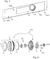
- the figure 1 illustrates a control interface 1000 for an appliance according to one embodiment.
- the control interface comprises a support plate 500 and a control device 100.
- the support plate 500 constitutes a control panel on which is mounted at least one control device 100 (here a single control device 100) and which may for example further comprise display means (not shown) associated with the control device. command 100.
- a user can act on the controller 100 to configure operating parameters of the appliance carrying this control panel.
- the support plate 500 has a face named " face having " 500a and a face called "back face” 500b.
- the "front face” of any element corresponds to the face of the element facing the user when the control device is installed in the appliance, that is to say say facing the outside of the appliance.
- the "backside" of an element refers to the opposite face of the front face, i.e., an inward facing face of the appliance.
- control panel may be attached to a wall of an appliance or may be part of the wall itself.
- This last embodiment is the case of a control interface forming part of the glass-ceramic plate of a hob or part of the door of a furnace.
- the support plate 500 comprises a support member 51 and an outer plate 52 fixed on the support member 51, for example by gluing.
- the outer plate 52 may, for example, be a decorative element.
- the support member 51 is attached to a wall of the appliance or constitutes a wall of the appliance.
- the outer plate 52 has an opening 53.
- the opening 53 may be in the form of a window to show, for example, display means (not shown in the figures) arranged between the support member 51 and the outer plate 52.
- the opening 53 may leave visible in addition to the display means, other control devices such as sensitive keys.
- the opening 53 has in this example a rectangular shape.
- the window may have other shapes in other embodiments.
- the support plate forming the control panel is formed by a single element.
- the support plate is a wall of a household appliance, the control device being directly fixed on this wall.
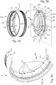
- the figure 2 illustrates in perspective according to an exploded view, a manual control device 100, or joystick for a household appliance (not shown in the figures) according to one embodiment.
- control device 100 In order to implement a command associated with an action from a user on the manual control device or joystick, the control device 100 is associated with a control axis 200.
- a movement (or change of position) action on the controller 100 causes a movement (or change of position) on the control axis 200.
- a movement action on the controller 100 may be defined as any action performed by a user of the appliance on the control device causing the modification of the position of a portion of the manual control device.
- the user By the action of movement, the user aims to implement a command, for example the establishment of a parameter to a specific value or the selection of a program of operation.
- a motion action can be, for example, a positioning of the controller 100 on a position to select a value for a parameter or to select a program, for example a value power of a cooking stove in a hob, or a cooking mode of a cooking oven.
- the manual control device or joystick 100 may be rotated or pushed by a user to for example select an operating parameter or a program of operation of the appliance.
- the control spindle 200 is mounted on an electronic card 2000 having control means necessary for the implementation of a command according to the movements of the control spindle 200.
- the manual control device or control lever 100 comprises a control element 100A comprising a moving part 1 mounted on a support piece 2.
- the moving part 1 comprises, as will be described with reference to the figure 3 , a movable ring 11, a transverse part 3 and a stop element 4.
- the moving part 1 is mounted on a first side of the support part 2 and is shaped to receive a movement action representative of a control.
- the support member 2 comprises, on a second side opposite said first side, fastening means for fixing said support member 2 to a support plate 500.
- support 2 is fixed on its second side to a support plate 500, the movable part 1 being fixed to the first side of the support part 2.
- the assembly formed by the mobile ring 11 and the transverse part 3 is rotatable relative to the support part 2, the transverse part 3 being movable in translation relative to the mobile ring 11.
- the element stop 4 limits the displacement in translation of the transverse part 3 with respect to the mobile ring 11.
- the assembly formed by the moving part 1, the support part 2 and the transverse part forms the control element 100A of the control device 100.
- a movement action on the manual control device 100 corresponds to a movement action on the moving part 1.
- the support part 2 and the moving part 1 comprise connecting means for connecting the movable part 1 and the support part 2 between them.
- the connecting means of the support part 2 and the movable part 1 cooperate with each other so as to keep these two parts connected, while allowing the mobile part 1 to move relative to the support part 2.
- the manual control device or control lever 100 further comprises a transmission element 30 transmitting a movement of the moving part 1 with respect to the support part 2 to the control shaft 200.
- the controller 100 further includes a locking member 6 which is for locking the position of the manual control device or joystick 100 on the support plate 500.
- the locking member will be described with reference to Figures 6A and 6B .
- the locking element 6 is mounted on the second side of said support member 2 and cooperates, as will be described, with the attachment means 26 of the support member to the support plate 500, to lock said support member 2.
- the moving part 1, the support part 2 and the transmission element 30 will be described in detail below.
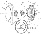
- the Figures 3A and 3B respectively illustrate the movable ring 11 of the moving part 1 and the support part 2 according to one embodiment.
- the figure 3C illustrates in perspective a sectional view of the movable ring.
- the support piece 2 ( figure 3B ) comprises a base 21 and a connecting element 22 to the movable ring 11, the base 21 extending in a plane P.
- the support piece 2 comprises a first face called “front face” (or first side) 2a and a second face called “back face” (or second side) 2b.
- the support member 2 has a central opening 29 having a shape and a size adequate to accommodate and allow the displacement of the transmission element 30 (not visible in these figures).
- the base 21 and the connecting element 22 are positioned around the central opening 29.
- the connecting element 22 projects from the base 21 in a direction perpendicular to a plane P in which the base 21 extends and towards the front face 2a of the support part 2.
- the connecting element 22 has a peripheral surface 20.
- the base 21 has substantially a crown shape, that is to say a surface formed by two concentric circles, and has a peripheral surface 210.
- the peripheral surfaces of the base 210 and the connecting element 20 are cylindrical, the circumference formed by the peripheral surface 20 of the connecting element being of smaller diameter than the peripheral surface 210 of the base 21.
- the mobile ring 11 ( figure 3A ) comprises a central opening 19.
- the movable ring 11 has a cylindrical shape in this embodiment.
- the shape and size of the central opening 19 are such that the movable ring 11 is mounted on the support piece 2, in particular that the movable ring 11 is mounted on the peripheral surface 20 of the connecting element 22 of the support part 2.
- the movable ring may be mounted on an inner surface of the support member of the support member.
- the movable ring has a front face 11a and a rear face 11b, the rear face 11b being positioned on the base 21 of the support piece 2 once the moving part 1, and in particular the movable ring 11 is mounted on the support part 2.
- the movable ring 11 and the connecting element 22 of the support part 2 are mounted one in contact with each other.
- the shapes of the movable ring 11 and the connecting element 22 of the support part 2 are complementary and the sizes are similar so that one can be inserted inside the other while allowing the rotation of one with respect to the other.
- the mobile ring 1, the base 21 and the connecting element 22 of the support part 2 are cylindrical.
- a first inner surface 11c of the movable ring 11 is mounted on the peripheral surface 20 of the connecting element 22.
- the movable ring 11c when the movable ring 11c is positioned on the support member 2, the first inner surface 11a of the movable ring 11 and the peripheral surface 20 of the connecting element 22 are concentric, the movable ring 11 being placed outside the connecting element 22, in particular outside the peripheral surface 20 of the connecting element 22.
- the circumference formed by the first inner surface 11c of the movable ring 11 is thus slightly greater than the circumference formed by the peripheral surface 20 of the connecting element 22.
- the movable ring 11 and the connecting element 22 of the support piece 2 respectively comprise connecting means 12, 23.
- the connecting means 12 of the mobile ring 11 comprise a groove or groove 12 formed at the rear face 1b of the mobile ring 11.
- the groove or groove 12 is formed on the first inner surface 11c of the movable ring 11 and cooperates with the connecting means 23 of the support piece 2 when the movable ring 11 is mounted on the piece of support 2.
- the first inner surface 11c is cylindrical and the groove 12 is formed in an entire circumference formed by the first inner surface 11c.
- the groove may be formed non-continuously along the circumference.
- the connecting means 23 of the support part 2 are formed in the connecting element 22 so as to maintain a continuity of the peripheral surface 20.
- the connecting means 23 are clipping members 23, the clipping members 23 cooperating with the groove or groove 12 of the movable ring 11 so that the movable ring 11 and the support part 2 remain interconnected. once the moving part 1, and in particular the mobile ring 11 is mounted on the support part 2.
- Each clip member 23 has a tab 23a projecting from the base 21 in a direction perpendicular to the plane P, the outer surface of the tab 23a being in continuity with the peripheral surface 20.
- the clipping member 23 further comprises a head 23b for engaging the clipping member 23 with the groove 12.
- the head 23b of the clipping element 23 is housed in the groove 12 when the mobile ring 11 is mounted on the support part 2.
- the number of clipping elements 23 is three, this number may be different in other embodiments.
- the rear face 11b of the mobile ring 11 is positioned in contact with a front face 21a of the base 21 and the connecting means 12 of the mobile ring 11 cooperate with the connecting means 23 of the support piece 2 so as to make integral the support piece 2 and the moving part 1, in particular the mobile ring 11.
- the clipping members 23 have a height from the base 21, such that they can fit into the groove 12 of the movable ring 11 and prevent any axial displacement of the mobile ring 11 with respect to the support part 2.
- the support piece 2 further comprises means for guiding the movement 24 of the mobile ring 11 with respect to the support piece 2.
- the movement guide means 24 comprise a set of protuberances or protuberances formed on the peripheral surface 20 of the connecting element 22.
- the protrusions or protuberances 24 have a half-cylinder shape extending on the peripheral surface 20. starting from the base 21 in a direction perpendicular to the plane P in which the base 21 extends.
- the rounded shape of the protuberances 24 makes it possible to guide the mobile ring 11 in movement relative to the support part 2.
- the shape of the excrescences 24 makes it possible to guide the mobile ring 11 in rotation with respect to the support part 2, and in particular with respect to the connecting element 22.
- the dimensions of the protuberances 24 as well as those of the peripheral surface 20 of the support piece 2 are determined so as to be able to introduce the connecting element 22 of the support piece 2 into the mobile ring 11
- the protuberances 24 form part of a cylinder of diameter substantially smaller than or equal to the diameter of the first internal surface 11c in order to allow the rotation without play of the mobile ring 11 with respect to the support part 2.
- the excrescences 24 are three in number and are equidistantly distributed on the peripheral surface 20 of the connecting element 22.
- the number of excrescences may be different and the shapes may vary while allowing the guide of the rotating ring in rotation relative to the support piece.
- a user exerts a rotational movement or a pushing movement on the mobile ring 11 when he wants to implement a command associated with the control device 100.
- the movable ring 11 has a second inner surface 11d disposed between the groove 12 and the front face 11a of the movable ring 11.
- second inner surface 11 d is composed of several faces 111 ( figure 3C ) forming a polygonal shape.
- the shape of the inner surface 11 d is complementary to that of the transverse element 3, as will be described with reference to the figure 4 .
- the support piece 2 further comprises fastening means 26 for fastening the support piece 2 to the support plate 500, as will be described with reference to FIG. Figure 5A .
- the fastening means 26 project from the base 21 in a direction perpendicular to the plane P in the opposite direction to the connecting element 22 and consequently to the moving part 1 when the moving part 1 is mounted on the part 2. In other words, the fastening means 26 extend towards the rear face 2b of the support piece 2.
- the fixing means 26 are positioned starting from a rear face of the base 21b and the connecting element 22 is positioned starting from the front face 21a of the base 21.
- the fixing means 26 comprise clipping elements.
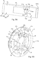
- the figure 4 illustrates in perspective a part of the movable part 1, the support part 2 and a transmission element 30 according to the embodiment (shown in FIGS. figures 2 and 3 ).
- the transmission element 30 is mounted between the moving part 1 and the control shaft 200.
- the transmission element 30 is intended to transmit a movement of the moving part 1 to the control shaft 200.
- a rotation exerted on the moving part 1 is transformed into a rotation of the control shaft 200.
- the moving part 1 and the transmission element 30 have complementary cooperation means allowing the transmission of a movement of the moving part 1 to the control axis 200.
- the transmission element 30 is not fixed to the moving part 1, that is to say that the transmission element 30 is independent of the moving part 1.
- the moving part 1 comprises a transverse part 3 positioned in contact with the movable ring 11. This transverse part 3 constitutes cooperation means of the moving part 1 with the transmission element 30.
- the transverse part 3 comprises a plate 31 positioned at the front of the moving part 1.
- the transverse part 3 is positioned inside the movable ring 11 in contact with a second inner surface 11 d (see FIG. figure 3A ), so that the plate 31 is disposed in a plane P1 parallel to the plane P in which the base 21 of the support part 2 extends when the moving part 1 is mounted on the support part 2.
- the plate 31 has a shape complementary to the second inner surface 11d of the mobile ring 11.
- the plate 31 has a polygonal shape.
- the second inner surface 11d of the movable ring 11 has a complementary shape so that the peripheral surface 31a of the plate 31 is in contact with the second inner surface 11d of the movable ring 11.
- Such a polygonal shape advantageously allows to allow axial displacement of the crosspiece 3 relative to the movable ring 11 while ensuring that the crosspiece 3 and the movable ring 11 are integral in rotation.
- the moving part 1 further comprises a stop element 4 (see figure 1 ) for stopping in translation along an axis X perpendicular to the plane P around which the control device 200 is located.
- the transverse part 3 is held in the mobile ring 11 by the stop element 4.
- the stop element 4 is in this embodiment a stop ring positioned in a front end or front edge 11a of the movable ring 11.
- the stop ring 4 is an element attached to the movable ring 11 and secured, for example by screwing, crimping, wrapping or gluing.
- the mobile ring itself, may comprise a rim ensuring the stopping of the support piece in translation along an axis X perpendicular to the plane P around which the control device is located, the stop ring and the mobile ring then forming a single piece.
- the transverse piece 3 further comprises at least one lug 32 projecting in a direction perpendicular to the plane P1 in which the plate 31 extends.
- the plate 31 When the transverse part 3 is positioned on the mobile ring 1, the plate 31 is placed towards the front face 11a of the mobile ring 11 and the lugs 32 towards the rear face 11b of the mobile ring 11.
- the lugs 32 constitute the cooperation means of the moving part 1 with the transmission element 30.
- the lugs 32 are two in number. Of course, the number of lugs may be different.
- the transmission element 30 is thus intended to transmit a movement of the moving part 1 to the control shaft 200, while allowing axial misalignment between the moving part 1 and the control axis 200.
- the transmission element 30 allows the transmission of a movement of the workpiece mobile 1 to the control axis 200 by overcoming the axial misalignment between the two elements.
- the transmission element 30 is in this embodiment of the " Oldham seal " type and comprises at least one opening 302 of complementary shape to a lug 32 of the transverse part 3 of the moving part 1.
- the opening 302 houses the lug 32 so that a movement of the transverse part 3 causes a movement of the transmission element 30.
- the transmission element 30 is housed in the central opening 29 formed in the support part 2.
- the transmission element 30 is fixed to the control shaft 200 so that when the moving part 1 receives a movement, the movement is transmitted to the control shaft 200.
- the lug 32 being housed by the opening 302 of the transmission element 30, rotates the transmission element 30, this rotation driving the control shaft 200 in rotation.
- the opening 302 constitutes means of cooperation of the transmission element 30 with the moving part 1.
- an axial translation movement on the transverse part 3 generates an axial translational movement of the transmission element 30, the latter generating an axial translation movement on the control axis 200.
- the transverse part 3 When the transverse part 3 is driven in axial translation due to a bearing action of a user, it returns to its initial position by means of spring parts 28 positioned at the front face 2a of the support part 2 .
- the transverse part 3 for receiving the user's support action and to move axially due to this support performs the function of push button.
- the control spindle 200 is thus driven in motion although there is no direct link between the moving part 1 and the control spindle 200.
- the transmission element 30 makes it possible to mount the moving part 1 relative to the support part 2, and to the support plate 500 on which the support part 2 is mounted, and not with respect to the axis 200.
- control axis 200 can be misaligned with respect to the moving part 1, this misalignment not being apparent on the control device 100 installed on a support plate 500.
- control device can be accurately positioned with respect to indicative marks, for example a parameter value or a program of operation.
- the moving part 1 when the moving part 1 is mounted on the support part 2, the moving part 1 can not be disassembled by a user.
- the stop ring 4 prevents disassembly of the transverse part 3 and the transverse part 3 prevents a user from deforming the connecting means 23 of the support part 2 in order to extract the moving part 1.
- FIGS. 5A and 5B illustrate in perspective the support plate 500 and the support part 2 of the embodiment of the figure 1 .
- the support plate 500 ( Figure 5A ) has an opening 50 shaped to receive the support piece 2.
- the opening 50 has a substantially circular shape having a diameter adapted to receive the support piece 2.
- the support plate 500 comprises a support member 51 and an outer plate 52.
- the support member 51 has an opening 51a.
- the opening 50 of the support plate 500 is formed by the opening 51a of the support member and the opening 53 of the outer plate 52.
- the support plate 500 comprises at least one tab 54 located at the opening 50 of the support plate 500, shaped to cooperate with the support part 2, as will be described below, so that the piece of support 2 is placed stably on the support plate 500.
- the support plate 500 has two lugs 54.
- the tabs 54 are formed on the outer plate 52.
- the tabs 54 are formed on a lateral side 53a of the opening 53 extending inwardly of the opening 53.
- the side lateral 53a on which are formed the legs 54 has a shape in a half-circle or half-moon 53aa between the two legs 54.
- the outer plate or decoration 52 is disposed on the support member 51 so that the opening 53, and in particular the tabs 54 and the half-circle portion 53aa of the lateral side 53a of the opening 53 are arranged in an overlay of the opening 51 formed in the support member 51.
- the opening 50 formed by the support member 51 and the outer plate 52 has a shape adapted or shaped to receive the support member 2, the support member 2 being placed on the support plate 500 stably.
- the opening 50 has a first portion of the contour formed in the support member 51 and a second portion of the contour formed by the lateral side 53a (including the legs 54 and the semicircular shape 53aa) of the window. 53 formed in the outer plate 52.
- first and second portions of the contour are not continuous, the second portion of the contour being located on the outer plate 52 and the first portion of the contour being located on the support 51 and thus being slightly offset rearward of the support plate 500 of the front face 52a of the outer plate 52.
- the support member 2 is shaped to be mounted on the opening 50 having such first and second contour portions.
- the rear face 21b of the base 21 of the support piece 2 is discontinuous, that is to say it comprises a first half-surface 21 x and a second half-surface 21 extending respectively in parallel planes.
- the planes have a distance between them of value substantially equal to the thickness of the outer plate 52.
- the first half-surface 21 x is intended to cooperate with the front surface 51a of the support element 51 or with the first part of the contour of the opening 50 and the second half-surface 21 is intended to cooperate with the face before 52a of the outer plate 52 or with the second part of the contour of the opening 50.
- the support plate could consist of a single element in which are formed a window leaving visible the display means and an opening for fixing the support device (this mode of realization is not shown in the figures).
- the opening of the outer plate and a window for showing display means of the outer plate are distinct (this embodiment is not shown in the figures).
- the support piece 2 comprises at least one notch 27 shaped to accommodate said at least one lug 54 of the support plate 500 so that the base 21 of the support piece 2 bears against the front face 500a of the support plate. support 500.
- the number of notches 27 is two, each notch 27 housing a tab 54.
- the notch 27 and the tab 54 have complementary shapes so that the tab 54 bears on the notch 27 once the support piece 2 is installed on the support plate 500.
- the notch 27 and the leg 54 form means of cooperation between the support member 2 and the support plate 500.
- These cooperation means also constitute means for positioning the support 2 relative to the support plate 500.
- the Figure 6A shows a rear view of the control interface 1000 of the figure 1 .
- the support member 51 of the support plate 500 is not shown in the figure so that the controller 100 is visible.
- Lateral faces 27b, 27c of the notch 27 of the support piece 2 are placed substantially in contact with the lateral faces 54b, 54c of the tab 54 of the support plate 500.
- the support piece 2 is immobilized in directions parallel to a plane P2 in which the support plate 500 extends, as well as in directions parallel to the plane P in which the base 21 of the support piece extends. 2.
- the support member 2 can not rotate with respect to the support plate 500 or the X-axis movements in a direction towards the rear face 500b of the support plate 500.
- the number of notches 27 and tabs 54 is two.
- the Figure 6A further illustrates fastening means 26 for attaching the support piece 2 to the support plate 52.
- the fixing means 26 are clipping elements on which a locking element 6 is positioned so as to immobilize the control device 100 on the support plate 500.
- the locking element 6 cooperates with the fastening means 26 of the support piece 2.
- the fastening means 26 are arranged in such a way as to be able to penetrate without effort into the opening 50, for example by entering into a circle of diameter substantially smaller than or equal to the diameter of the opening 50.
- the locking element 6 is illustrated by the Figure 6B .
- the locking member 6 is for locking the position of the manual control device or control handle 100 on the support plate 500.
- the locking element 6 extends on a plane which is parallel to the plane P on which the base 21 extends when the locking element 6 is located in the control device 100.
- the locking member 6 When mounting the controller 100 on a support plate 500, the locking member 6 is positioned on the rear face 500b of the support plate 500, i.e. on the opposite side of the support plate 500 to the side on which is positioned the base 21 of the support piece 2.
- locking element 6 is mounted on the rear face 2b or the second side of the support piece 2.
- the locking element 6 has a central opening 60 so as to surround the assembly formed by the transmission element 30 and the control shaft 200.
- the locking element 6 has a central portion 62 having substantially a crown or cylinder shape about the X axis (see figure 2 ) and forming the central opening 60.
- the central portion 62 surrounds the transmission member 30 and the control shaft 200 once the controller 100 is mounted.
- the central portion 62 comprises a peripheral surface 64. This peripheral surface 64 is disposed opposite an inner face 26a of the clipping element 26 of the support part 2 when the locking element 6 is mounted in the device of FIG. command 100.
- the locking element 6 further comprises at least one end 63 extending radially from the peripheral surface 64 and being shaped to come into contact with an external face 26b of the clipping element 26 of the support part 2.
- the locking element 6, and in particular the end 63 cooperates with the fastening means 26 of the support part 2 so as to immobilize the control device 100.
- the locking element 6 has three ends 63, each end 63 cooperating with a fixing means 26 of the support part 2.
- Each end 63 comprises a periphery 630 having a peripheral surface 631 which is in continuity with the peripheral surface 64 of the central portion 62 of the locking element 6.
- Each end 63 of the locking element 6 comprises a hem or engaging piece 61.
- the hem or engagement piece 61 extends transversely to the periphery 630.
- the hem or engaging piece 61 extends in a direction perpendicular to the plane in which the peripheral surface 631 of the end 63 extends towards the central portion 62.
- the hems or engaging pieces 61 engage respectively in the clipping members 26 of the support member 2, when the controller 100 is mounted.
- the hems 61 engaged in the clipping elements 23, block the clipping members 26 so that the support piece 2 can be dismounted only by removing the locking element 6.
- the central part 62 of the locking element 6 is housed in the embodiment described by the central opening 29 of the support part 2.
- the locking element 6 comprises at least one blocking element or hem 61 intended to cooperate with a clipping element 26 of the support part 2.
- the hem 61 has a shape complementary to a clipping member 26, so that the hem 61 and the clipping member 26 cooperate, the locking member 6 being retained by this cooperation.
- clipping elements are known to those skilled in the art. It will be recalled, however, that the elastic deformation of the clipping elements 26 allows the insertion of the locking element 6 and then the return of the clipping elements 26 substantially to their initial position, while maintaining a significant deformation of the locking element. 6, causing a significant constraint of the locking element 6 on the hem 61.
- the locking element 6 once mounted on the support part 2 and the support plate 500, rests on the rear face 500b of the support plate 500 and is retained in this position by the cooperation between the hem 61 and the clip member 26 of the support piece 2.
- the locking element 6 comprises a front face 6a which is positioned at the ends 63 resting on the rear face 500b of the support plate 500, in particular on the rear face 51b of the support element. support 51 (not shown on the Figure 6A ), when the control device 100 is mounted on the support plate 500.
- the support part 2 can not be dismantled by the front face 500a of the support plate 500.
- a user of a household appliance comprising such a control device 100 or such a control interface 1000 could not dismount.
- the control device 100 according to the invention outside the electronic device, preventing the user from being in contact with parts of the household appliance that may represent a danger.
- the locking of the support member with respect to the support plate could be carried out according to an alternative embodiment.
- clipping members could be arranged at the periphery of the support part 2 so that the end of the latter fits into a circle of diameter substantially greater than the opening of the support plate, the elements of clipping deforming during the insertion of the rear part of the support part into the opening and then returning to their initial position and bearing on the rear face of the support plate.
- the support piece 2 is made of electrically insulating material.
- control shaft 200 is electrically insulated from the support plate 52, this support plate 500 being in direct contact with the user.
Landscapes
- Physics & Mathematics (AREA)
- General Physics & Mathematics (AREA)
- Engineering & Computer Science (AREA)
- Automation & Control Theory (AREA)
- Mechanical Control Devices (AREA)
Applications Claiming Priority (1)
| Application Number | Priority Date | Filing Date | Title |
|---|---|---|---|
| FR1660196A FR3057989B1 (fr) | 2016-10-20 | 2016-10-20 | Dispositif de commande manuelle pour un appareil electromenager |
Publications (2)
| Publication Number | Publication Date |
|---|---|
| EP3312858A1 true EP3312858A1 (de) | 2018-04-25 |
| EP3312858B1 EP3312858B1 (de) | 2021-08-18 |
Family
ID=58455110
Family Applications (1)
| Application Number | Title | Priority Date | Filing Date |
|---|---|---|---|
| EP17197200.3A Active EP3312858B1 (de) | 2016-10-20 | 2017-10-19 | Manuelle bedienungsvorrichtung für ein elektrohaushaltsgerät |
Country Status (4)
| Country | Link |
|---|---|
| EP (1) | EP3312858B1 (de) |
| ES (1) | ES2894853T3 (de) |
| FR (1) | FR3057989B1 (de) |
| MA (1) | MA43854A (de) |
Families Citing this family (1)
| Publication number | Priority date | Publication date | Assignee | Title |
|---|---|---|---|---|
| DE102022108429A1 (de) * | 2022-04-07 | 2023-10-12 | Abb Schweiz Ag | Gerät der Hausinstallationstechnik |
Citations (6)
| Publication number | Priority date | Publication date | Assignee | Title |
|---|---|---|---|---|
| US5430249A (en) * | 1993-06-07 | 1995-07-04 | Motorola, Inc. | Knob assembly |
| US20050002664A1 (en) * | 2003-07-04 | 2005-01-06 | Chi-Yu Liao | Multi-function button with mode selection |
| US20080289940A1 (en) * | 2007-05-25 | 2008-11-27 | Samsung Electronics Co., Ltd. | Washing machine and control panel assembly thereof |
| DE102008013945A1 (de) * | 2008-03-12 | 2009-09-17 | Stiebel Eltron Gmbh & Co. Kg | Bedienelement für ein Haustechnikgerät und Haustechnikgerät |
| US20120087721A1 (en) * | 2009-06-11 | 2012-04-12 | Masahiro Nishijima | Structure for preventing encoder button from coming out of place |
| DE102011007236A1 (de) * | 2011-04-12 | 2012-10-18 | BSH Bosch und Siemens Hausgeräte GmbH | Bedienelement für ein Haushaltsgerät und Haushaltsgerät |
-
2016
- 2016-10-20 FR FR1660196A patent/FR3057989B1/fr active Active
-
2017
- 2017-10-19 EP EP17197200.3A patent/EP3312858B1/de active Active
- 2017-10-19 ES ES17197200T patent/ES2894853T3/es active Active
- 2017-10-19 MA MA043854A patent/MA43854A/fr unknown
Patent Citations (6)
| Publication number | Priority date | Publication date | Assignee | Title |
|---|---|---|---|---|
| US5430249A (en) * | 1993-06-07 | 1995-07-04 | Motorola, Inc. | Knob assembly |
| US20050002664A1 (en) * | 2003-07-04 | 2005-01-06 | Chi-Yu Liao | Multi-function button with mode selection |
| US20080289940A1 (en) * | 2007-05-25 | 2008-11-27 | Samsung Electronics Co., Ltd. | Washing machine and control panel assembly thereof |
| DE102008013945A1 (de) * | 2008-03-12 | 2009-09-17 | Stiebel Eltron Gmbh & Co. Kg | Bedienelement für ein Haustechnikgerät und Haustechnikgerät |
| US20120087721A1 (en) * | 2009-06-11 | 2012-04-12 | Masahiro Nishijima | Structure for preventing encoder button from coming out of place |
| DE102011007236A1 (de) * | 2011-04-12 | 2012-10-18 | BSH Bosch und Siemens Hausgeräte GmbH | Bedienelement für ein Haushaltsgerät und Haushaltsgerät |
Also Published As
| Publication number | Publication date |
|---|---|
| ES2894853T3 (es) | 2022-02-16 |
| EP3312858B1 (de) | 2021-08-18 |
| MA43854A (fr) | 2021-04-07 |
| FR3057989B1 (fr) | 2018-11-02 |
| FR3057989A1 (fr) | 2018-04-27 |
Similar Documents
| Publication | Publication Date | Title |
|---|---|---|
| EP1344476B1 (de) | Dampfdruckkochgerät mit einer drehenden Verriegelungsvorrichtung | |
| EP3312862B1 (de) | Manuelle bedienungsvorrichtung für ein elektrohaushaltsgerät | |
| EP2687132B1 (de) | Druckkochgerät mit verbesserter Bedienungsvorrichtung | |
| FR2851491A1 (fr) | Outil electrique a bouton d'actionnement pour commander le fonctionnement soit en mode entrainement en rotation soie en mode frappe | |
| EP2433533B1 (de) | Haushaltsgerät mit einem Gefäß, das ein von einem Motor angetriebenes Schneidewerkzeug umfasst | |
| EP0981005A1 (de) | Kupplungsvorrichtung eines Gerätes auf einer unter Druck stehenden Kassette | |
| EP2433534B1 (de) | Haushaltsgerät mit einem Gefäß, das ein von einem Motor angetriebenes Schneidewerkzeug umfasst | |
| EP3312858B1 (de) | Manuelle bedienungsvorrichtung für ein elektrohaushaltsgerät | |
| FR2908620A1 (fr) | Appareil de preparation culinaire comportant des moyens particuliers d'immobilisation du recipient | |
| EP2535785B2 (de) | Vorrichtung zur Steuerung eines Haushaltsgeräts | |
| EP2937027B1 (de) | Elektrohaushaltsgerät zur essenszubereitung, das einen entfernbaren behälter umfasst, der durch eine einfache verschiebungsbewegung auf einem gehäuse abgestellt werden kann | |
| EP1566129B1 (de) | Elektrisches Haushaltsgerät zur Nahrungszubereitung | |
| EP1072811B1 (de) | Haltevorrichtung für zwei ringförmige Federn der Synchronsperre in einer Synchronisationsnabe geeignet für Synchronisiereinrichtungen bei Kraftfahrzeug-Getrieben | |
| EP2438841B1 (de) | Elektrogerät zur Zubereitung von Speisen, das mit einem Zubehör zur Aufhängung von Küchenwerkzeugen ausgestattet ist | |
| EP1030332A1 (de) | Bedienungsschalter für elektrische Kochgeräte | |
| EP1529472B1 (de) | Elektrisches Haushaltsgerät zur Nahrungszubereitung mit einer lösbar an einem Gehäuse gekoppelten Zusatzvorrichtung | |
| EP2384676B1 (de) | Mit einer Sicherheitsvorrichtung verschließbares Elektro-Haushaltsgerät zur Essenszubereitung | |
| EP2433531B1 (de) | Vorrichtung zum Befestigen eines Gefässes oder eines Deckels eines Haushaltsgeräts | |
| WO2012045977A1 (fr) | Chaussure à semelle et tige interchangeables l'une par rapport à l'autre | |
| FR2913737A1 (fr) | Appareil electromenager comprenant un bandeau de commande et un moyen de verrouillage | |
| EP0225222B1 (de) | Elektrisches Gerät mit verbessertem Zusammenbau | |
| EP2549138A1 (de) | Doppelscheibenkupplung mit gestanztem Auflageelement | |
| EP3829014A1 (de) | Gerät mit einer kippbaren gerätehalterung und einem verriegelungssystem, das mittels eines kippbaren betätigungsknopfes entriegelt werden kann | |
| FR2623885A1 (fr) | Table de cuisson | |
| FR2900216A1 (fr) | Cartouche de gaz |
Legal Events
| Date | Code | Title | Description |
|---|---|---|---|
| PUAI | Public reference made under article 153(3) epc to a published international application that has entered the european phase |
Free format text: ORIGINAL CODE: 0009012 |
|
| STAA | Information on the status of an ep patent application or granted ep patent |
Free format text: STATUS: THE APPLICATION HAS BEEN PUBLISHED |
|
| AK | Designated contracting states |
Kind code of ref document: A1 Designated state(s): AL AT BE BG CH CY CZ DE DK EE ES FI FR GB GR HR HU IE IS IT LI LT LU LV MC MK MT NL NO PL PT RO RS SE SI SK SM TR |
|
| AX | Request for extension of the european patent |
Extension state: BA ME |
|
| STAA | Information on the status of an ep patent application or granted ep patent |
Free format text: STATUS: REQUEST FOR EXAMINATION WAS MADE |
|
| 17P | Request for examination filed |
Effective date: 20181012 |
|
| RAV | Requested validation state of the european patent: fee paid |
Extension state: MA Effective date: 20181012 |
|
| RBV | Designated contracting states (corrected) |
Designated state(s): AL AT BE BG CH CY CZ DE DK EE ES FI FR GB GR HR HU IE IS IT LI LT LU LV MC MK MT NL NO PL PT RO RS SE SI SK SM TR |
|
| STAA | Information on the status of an ep patent application or granted ep patent |
Free format text: STATUS: EXAMINATION IS IN PROGRESS |
|
| 17Q | First examination report despatched |
Effective date: 20200214 |
|
| GRAP | Despatch of communication of intention to grant a patent |
Free format text: ORIGINAL CODE: EPIDOSNIGR1 |
|
| STAA | Information on the status of an ep patent application or granted ep patent |
Free format text: STATUS: GRANT OF PATENT IS INTENDED |
|
| INTG | Intention to grant announced |
Effective date: 20210311 |
|
| RIN1 | Information on inventor provided before grant (corrected) |
Inventor name: BRASILLET, PASCAL |
|
| GRAS | Grant fee paid |
Free format text: ORIGINAL CODE: EPIDOSNIGR3 |
|
| GRAA | (expected) grant |
Free format text: ORIGINAL CODE: 0009210 |
|
| STAA | Information on the status of an ep patent application or granted ep patent |
Free format text: STATUS: THE PATENT HAS BEEN GRANTED |
|
| AK | Designated contracting states |
Kind code of ref document: B1 Designated state(s): AL AT BE BG CH CY CZ DE DK EE ES FI FR GB GR HR HU IE IS IT LI LT LU LV MC MK MT NL NO PL PT RO RS SE SI SK SM TR |
|
| REG | Reference to a national code |
Ref country code: GB Ref legal event code: FG4D Free format text: NOT ENGLISH |
|
| REG | Reference to a national code |
Ref country code: CH Ref legal event code: EP |
|
| REG | Reference to a national code |
Ref country code: DE Ref legal event code: R096 Ref document number: 602017044184 Country of ref document: DE |
|
| REG | Reference to a national code |
Ref country code: IE Ref legal event code: FG4D Free format text: LANGUAGE OF EP DOCUMENT: FRENCH Ref country code: AT Ref legal event code: REF Ref document number: 1422380 Country of ref document: AT Kind code of ref document: T Effective date: 20210915 |
|
| REG | Reference to a national code |
Ref country code: LT Ref legal event code: MG9D |
|
| REG | Reference to a national code |
Ref country code: NL Ref legal event code: MP Effective date: 20210818 |
|
| REG | Reference to a national code |
Ref country code: AT Ref legal event code: MK05 Ref document number: 1422380 Country of ref document: AT Kind code of ref document: T Effective date: 20210818 |
|
| PG25 | Lapsed in a contracting state [announced via postgrant information from national office to epo] |
Ref country code: RS Free format text: LAPSE BECAUSE OF FAILURE TO SUBMIT A TRANSLATION OF THE DESCRIPTION OR TO PAY THE FEE WITHIN THE PRESCRIBED TIME-LIMIT Effective date: 20210818 Ref country code: SE Free format text: LAPSE BECAUSE OF FAILURE TO SUBMIT A TRANSLATION OF THE DESCRIPTION OR TO PAY THE FEE WITHIN THE PRESCRIBED TIME-LIMIT Effective date: 20210818 Ref country code: HR Free format text: LAPSE BECAUSE OF FAILURE TO SUBMIT A TRANSLATION OF THE DESCRIPTION OR TO PAY THE FEE WITHIN THE PRESCRIBED TIME-LIMIT Effective date: 20210818 Ref country code: LT Free format text: LAPSE BECAUSE OF FAILURE TO SUBMIT A TRANSLATION OF THE DESCRIPTION OR TO PAY THE FEE WITHIN THE PRESCRIBED TIME-LIMIT Effective date: 20210818 Ref country code: BG Free format text: LAPSE BECAUSE OF FAILURE TO SUBMIT A TRANSLATION OF THE DESCRIPTION OR TO PAY THE FEE WITHIN THE PRESCRIBED TIME-LIMIT Effective date: 20211118 Ref country code: AT Free format text: LAPSE BECAUSE OF FAILURE TO SUBMIT A TRANSLATION OF THE DESCRIPTION OR TO PAY THE FEE WITHIN THE PRESCRIBED TIME-LIMIT Effective date: 20210818 Ref country code: NO Free format text: LAPSE BECAUSE OF FAILURE TO SUBMIT A TRANSLATION OF THE DESCRIPTION OR TO PAY THE FEE WITHIN THE PRESCRIBED TIME-LIMIT Effective date: 20211118 Ref country code: PT Free format text: LAPSE BECAUSE OF FAILURE TO SUBMIT A TRANSLATION OF THE DESCRIPTION OR TO PAY THE FEE WITHIN THE PRESCRIBED TIME-LIMIT Effective date: 20211220 Ref country code: FI Free format text: LAPSE BECAUSE OF FAILURE TO SUBMIT A TRANSLATION OF THE DESCRIPTION OR TO PAY THE FEE WITHIN THE PRESCRIBED TIME-LIMIT Effective date: 20210818 |
|
| REG | Reference to a national code |
Ref country code: ES Ref legal event code: FG2A Ref document number: 2894853 Country of ref document: ES Kind code of ref document: T3 Effective date: 20220216 |
|
| PG25 | Lapsed in a contracting state [announced via postgrant information from national office to epo] |
Ref country code: PL Free format text: LAPSE BECAUSE OF FAILURE TO SUBMIT A TRANSLATION OF THE DESCRIPTION OR TO PAY THE FEE WITHIN THE PRESCRIBED TIME-LIMIT Effective date: 20210818 Ref country code: LV Free format text: LAPSE BECAUSE OF FAILURE TO SUBMIT A TRANSLATION OF THE DESCRIPTION OR TO PAY THE FEE WITHIN THE PRESCRIBED TIME-LIMIT Effective date: 20210818 Ref country code: GR Free format text: LAPSE BECAUSE OF FAILURE TO SUBMIT A TRANSLATION OF THE DESCRIPTION OR TO PAY THE FEE WITHIN THE PRESCRIBED TIME-LIMIT Effective date: 20211119 |
|
| PG25 | Lapsed in a contracting state [announced via postgrant information from national office to epo] |
Ref country code: NL Free format text: LAPSE BECAUSE OF FAILURE TO SUBMIT A TRANSLATION OF THE DESCRIPTION OR TO PAY THE FEE WITHIN THE PRESCRIBED TIME-LIMIT Effective date: 20210818 |
|
| PG25 | Lapsed in a contracting state [announced via postgrant information from national office to epo] |
Ref country code: DK Free format text: LAPSE BECAUSE OF FAILURE TO SUBMIT A TRANSLATION OF THE DESCRIPTION OR TO PAY THE FEE WITHIN THE PRESCRIBED TIME-LIMIT Effective date: 20210818 |
|
| REG | Reference to a national code |
Ref country code: DE Ref legal event code: R097 Ref document number: 602017044184 Country of ref document: DE |
|
| REG | Reference to a national code |
Ref country code: CH Ref legal event code: PL |
|
| PG25 | Lapsed in a contracting state [announced via postgrant information from national office to epo] |
Ref country code: SM Free format text: LAPSE BECAUSE OF FAILURE TO SUBMIT A TRANSLATION OF THE DESCRIPTION OR TO PAY THE FEE WITHIN THE PRESCRIBED TIME-LIMIT Effective date: 20210818 Ref country code: SK Free format text: LAPSE BECAUSE OF FAILURE TO SUBMIT A TRANSLATION OF THE DESCRIPTION OR TO PAY THE FEE WITHIN THE PRESCRIBED TIME-LIMIT Effective date: 20210818 Ref country code: RO Free format text: LAPSE BECAUSE OF FAILURE TO SUBMIT A TRANSLATION OF THE DESCRIPTION OR TO PAY THE FEE WITHIN THE PRESCRIBED TIME-LIMIT Effective date: 20210818 Ref country code: EE Free format text: LAPSE BECAUSE OF FAILURE TO SUBMIT A TRANSLATION OF THE DESCRIPTION OR TO PAY THE FEE WITHIN THE PRESCRIBED TIME-LIMIT Effective date: 20210818 Ref country code: CZ Free format text: LAPSE BECAUSE OF FAILURE TO SUBMIT A TRANSLATION OF THE DESCRIPTION OR TO PAY THE FEE WITHIN THE PRESCRIBED TIME-LIMIT Effective date: 20210818 Ref country code: AL Free format text: LAPSE BECAUSE OF FAILURE TO SUBMIT A TRANSLATION OF THE DESCRIPTION OR TO PAY THE FEE WITHIN THE PRESCRIBED TIME-LIMIT Effective date: 20210818 |
|
| REG | Reference to a national code |
Ref country code: BE Ref legal event code: MM Effective date: 20211031 |
|
| PLBE | No opposition filed within time limit |
Free format text: ORIGINAL CODE: 0009261 |
|
| STAA | Information on the status of an ep patent application or granted ep patent |
Free format text: STATUS: NO OPPOSITION FILED WITHIN TIME LIMIT |
|
| PG25 | Lapsed in a contracting state [announced via postgrant information from national office to epo] |
Ref country code: MC Free format text: LAPSE BECAUSE OF FAILURE TO SUBMIT A TRANSLATION OF THE DESCRIPTION OR TO PAY THE FEE WITHIN THE PRESCRIBED TIME-LIMIT Effective date: 20210818 |
|
| 26N | No opposition filed |
Effective date: 20220519 |
|
| GBPC | Gb: european patent ceased through non-payment of renewal fee |
Effective date: 20211118 |
|
| PG25 | Lapsed in a contracting state [announced via postgrant information from national office to epo] |
Ref country code: LU Free format text: LAPSE BECAUSE OF NON-PAYMENT OF DUE FEES Effective date: 20211019 Ref country code: BE Free format text: LAPSE BECAUSE OF NON-PAYMENT OF DUE FEES Effective date: 20211031 |
|
| PG25 | Lapsed in a contracting state [announced via postgrant information from national office to epo] |
Ref country code: SI Free format text: LAPSE BECAUSE OF FAILURE TO SUBMIT A TRANSLATION OF THE DESCRIPTION OR TO PAY THE FEE WITHIN THE PRESCRIBED TIME-LIMIT Effective date: 20210818 Ref country code: LI Free format text: LAPSE BECAUSE OF NON-PAYMENT OF DUE FEES Effective date: 20211031 Ref country code: CH Free format text: LAPSE BECAUSE OF NON-PAYMENT OF DUE FEES Effective date: 20211031 |
|
| PG25 | Lapsed in a contracting state [announced via postgrant information from national office to epo] |
Ref country code: IE Free format text: LAPSE BECAUSE OF NON-PAYMENT OF DUE FEES Effective date: 20211019 Ref country code: GB Free format text: LAPSE BECAUSE OF NON-PAYMENT OF DUE FEES Effective date: 20211118 |
|
| PG25 | Lapsed in a contracting state [announced via postgrant information from national office to epo] |
Ref country code: HU Free format text: LAPSE BECAUSE OF FAILURE TO SUBMIT A TRANSLATION OF THE DESCRIPTION OR TO PAY THE FEE WITHIN THE PRESCRIBED TIME-LIMIT; INVALID AB INITIO Effective date: 20171019 |
|
| PG25 | Lapsed in a contracting state [announced via postgrant information from national office to epo] |
Ref country code: CY Free format text: LAPSE BECAUSE OF FAILURE TO SUBMIT A TRANSLATION OF THE DESCRIPTION OR TO PAY THE FEE WITHIN THE PRESCRIBED TIME-LIMIT Effective date: 20210818 |
|
| PG25 | Lapsed in a contracting state [announced via postgrant information from national office to epo] |
Ref country code: MK Free format text: LAPSE BECAUSE OF FAILURE TO SUBMIT A TRANSLATION OF THE DESCRIPTION OR TO PAY THE FEE WITHIN THE PRESCRIBED TIME-LIMIT Effective date: 20210818 |
|
| VS25 | Lapsed in a validation state [announced via postgrant information from nat. office to epo] |
Ref country code: MA Free format text: LAPSE BECAUSE OF FAILURE TO SUBMIT A TRANSLATION OF THE DESCRIPTION OR TO PAY THE FEE WITHIN THE PRESCRIBED TIME-LIMIT Effective date: 20210818 |
|
| PG25 | Lapsed in a contracting state [announced via postgrant information from national office to epo] |
Ref country code: MT Free format text: LAPSE BECAUSE OF FAILURE TO SUBMIT A TRANSLATION OF THE DESCRIPTION OR TO PAY THE FEE WITHIN THE PRESCRIBED TIME-LIMIT Effective date: 20210818 |
|
| PG25 | Lapsed in a contracting state [announced via postgrant information from national office to epo] |
Ref country code: TR Free format text: LAPSE BECAUSE OF FAILURE TO SUBMIT A TRANSLATION OF THE DESCRIPTION OR TO PAY THE FEE WITHIN THE PRESCRIBED TIME-LIMIT Effective date: 20210818 |
|
| PGFP | Annual fee paid to national office [announced via postgrant information from national office to epo] |
Ref country code: DE Payment date: 20251015 Year of fee payment: 9 |
|
| PGFP | Annual fee paid to national office [announced via postgrant information from national office to epo] |
Ref country code: IT Payment date: 20251007 Year of fee payment: 9 |
|
| PGFP | Annual fee paid to national office [announced via postgrant information from national office to epo] |
Ref country code: FR Payment date: 20251022 Year of fee payment: 9 |
|
| PGFP | Annual fee paid to national office [announced via postgrant information from national office to epo] |
Ref country code: ES Payment date: 20251110 Year of fee payment: 9 |