EP3610962A1 - Pressformkörper, strukturelement für kraftfahrzeuge damit und herstellungsverfahren für pressformkörper - Google Patents
Pressformkörper, strukturelement für kraftfahrzeuge damit und herstellungsverfahren für pressformkörper Download PDFInfo
- Publication number
- EP3610962A1 EP3610962A1 EP18784833.8A EP18784833A EP3610962A1 EP 3610962 A1 EP3610962 A1 EP 3610962A1 EP 18784833 A EP18784833 A EP 18784833A EP 3610962 A1 EP3610962 A1 EP 3610962A1
- Authority
- EP
- European Patent Office
- Prior art keywords
- formed product
- portions
- press formed
- press
- vertical wall
- Prior art date
- Legal status (The legal status is an assumption and is not a legal conclusion. Google has not performed a legal analysis and makes no representation as to the accuracy of the status listed.)
- Granted
Links
Images





Classifications
-
- B—PERFORMING OPERATIONS; TRANSPORTING
- B21—MECHANICAL METAL-WORKING WITHOUT ESSENTIALLY REMOVING MATERIAL; PUNCHING METAL
- B21D—WORKING OR PROCESSING OF SHEET METAL OR METAL TUBES, RODS OR PROFILES WITHOUT ESSENTIALLY REMOVING MATERIAL; PUNCHING METAL
- B21D22/00—Shaping without cutting, by stamping, spinning, or deep-drawing
- B21D22/20—Deep-drawing
- B21D22/26—Deep-drawing for making peculiarly, e.g. irregularly, shaped articles
-
- B—PERFORMING OPERATIONS; TRANSPORTING
- B21—MECHANICAL METAL-WORKING WITHOUT ESSENTIALLY REMOVING MATERIAL; PUNCHING METAL
- B21D—WORKING OR PROCESSING OF SHEET METAL OR METAL TUBES, RODS OR PROFILES WITHOUT ESSENTIALLY REMOVING MATERIAL; PUNCHING METAL
- B21D19/00—Flanging or other edge treatment, e.g. of tubes
-
- B—PERFORMING OPERATIONS; TRANSPORTING
- B21—MECHANICAL METAL-WORKING WITHOUT ESSENTIALLY REMOVING MATERIAL; PUNCHING METAL
- B21D—WORKING OR PROCESSING OF SHEET METAL OR METAL TUBES, RODS OR PROFILES WITHOUT ESSENTIALLY REMOVING MATERIAL; PUNCHING METAL
- B21D22/00—Shaping without cutting, by stamping, spinning, or deep-drawing
- B21D22/02—Stamping using rigid devices or tools
- B21D22/06—Stamping using rigid devices or tools having relatively-movable die parts
-
- B—PERFORMING OPERATIONS; TRANSPORTING
- B21—MECHANICAL METAL-WORKING WITHOUT ESSENTIALLY REMOVING MATERIAL; PUNCHING METAL
- B21D—WORKING OR PROCESSING OF SHEET METAL OR METAL TUBES, RODS OR PROFILES WITHOUT ESSENTIALLY REMOVING MATERIAL; PUNCHING METAL
- B21D24/00—Special deep-drawing arrangements in, or in connection with, presses
-
- B—PERFORMING OPERATIONS; TRANSPORTING
- B21—MECHANICAL METAL-WORKING WITHOUT ESSENTIALLY REMOVING MATERIAL; PUNCHING METAL
- B21D—WORKING OR PROCESSING OF SHEET METAL OR METAL TUBES, RODS OR PROFILES WITHOUT ESSENTIALLY REMOVING MATERIAL; PUNCHING METAL
- B21D24/00—Special deep-drawing arrangements in, or in connection with, presses
- B21D24/005—Multi-stage presses
-
- B—PERFORMING OPERATIONS; TRANSPORTING
- B21—MECHANICAL METAL-WORKING WITHOUT ESSENTIALLY REMOVING MATERIAL; PUNCHING METAL
- B21D—WORKING OR PROCESSING OF SHEET METAL OR METAL TUBES, RODS OR PROFILES WITHOUT ESSENTIALLY REMOVING MATERIAL; PUNCHING METAL
- B21D37/00—Tools as parts of machines covered by this subclass
- B21D37/08—Dies with different parts for several steps in a process
-
- B—PERFORMING OPERATIONS; TRANSPORTING
- B21—MECHANICAL METAL-WORKING WITHOUT ESSENTIALLY REMOVING MATERIAL; PUNCHING METAL
- B21D—WORKING OR PROCESSING OF SHEET METAL OR METAL TUBES, RODS OR PROFILES WITHOUT ESSENTIALLY REMOVING MATERIAL; PUNCHING METAL
- B21D53/00—Making other particular articles
- B21D53/88—Making other particular articles other parts for vehicles, e.g. cowlings, mudguards
-
- B—PERFORMING OPERATIONS; TRANSPORTING
- B62—LAND VEHICLES FOR TRAVELLING OTHERWISE THAN ON RAILS
- B62D—MOTOR VEHICLES; TRAILERS
- B62D25/00—Superstructure or monocoque structure sub-units; Parts or details thereof not otherwise provided for
- B62D25/20—Floors or bottom sub-units
-
- B—PERFORMING OPERATIONS; TRANSPORTING
- B62—LAND VEHICLES FOR TRAVELLING OTHERWISE THAN ON RAILS
- B62D—MOTOR VEHICLES; TRAILERS
- B62D25/00—Superstructure or monocoque structure sub-units; Parts or details thereof not otherwise provided for
- B62D25/04—Door pillars ; windshield pillars
-
- B—PERFORMING OPERATIONS; TRANSPORTING
- B62—LAND VEHICLES FOR TRAVELLING OTHERWISE THAN ON RAILS
- B62D—MOTOR VEHICLES; TRAILERS
- B62D25/00—Superstructure or monocoque structure sub-units; Parts or details thereof not otherwise provided for
- B62D25/06—Fixed roofs
Definitions
- the present invention relates to a press formed product, an automobile structural member with the press formed product, and a method for producing the press formed product.
- Patent Literature 1 Japanese Patent Application Publication No. 2008-265609
- Patent Literature 2 Japanese Patent Application Publication No. 2008-155749
- an impact absorbing member which includes a portion where a steel sheet is folded over into three layers.
- Patent Literature 3 Japanese Patent Application Publication No. 2010-242168 discloses a method for forming a recessed portion on a wall portion of a member having a substantially hat shape in cross section. In this method, the wall portion is pressed by a power supply roller, thus forming the recessed portion. Accordingly, a portion which projects from the wall portion is not formed with this method before the recessed portion is formed.
- Patent Literature 4 Japanese Patent Application Publication No. 2011-67841
- Patent Literature 5 Japanese Patent Application Publication No. 2011-83807
- Patent Literature 6 Japanese Patent Application Publication No. 2013-27894
- Patent Literatures 4 and 5 take a component having a hat shape in cross section which has a large number of ridge lines in cross section (paragraph [0003] of Patent Literatures 4 and 5). Further, as an example of a component having high collision safety even without using a high tensile strength material, Patent Literatures 4 to 6 take a component where recessed portions (bead portions) are formed along the longitudinal direction (paragraph [0003] of Patent Literatures 4 and 5, and paragraph [0004] of Patent Literature 6).
- Patent Literature 4 discloses, as a component having high safety even without using a high tensile strength material, a component having a hollow columnar shape where connection regions between vertical wall portions and a top wall portion bulge outward. In order to increase the number of ridge lines in cross section, the bulged portion is not folded.
- Patent Literature 5 discloses, as a method for producing a component having high safety even without using a high tensile strength material, a method for producing a component having a hat shape in cross section where groove-shaped bead portions are formed on vertical wall portions along the longitudinal direction.
- Patent Literature 6 discloses, as a component having high safety even without using a high tensile strength material, a frame component which includes reinforcing portions each of which is formed at a connection portion between a top wall portion and a vertical wall portion. This reinforcing portion is formed of an overlapping portion rolled into a cylindrical shape ([0015] of Patent Literature 6).
- a press formed product is a press formed product formed from a single steel sheet.
- This press formed product includes two vertical wall portions, a top plate portion which connects the two vertical wall portions with each other, and at least one projecting portion which projects from at least one boundary portion of two boundary portions each of which connects the vertical wall portion and the top plate portion with each other.
- the steel sheet extending from the vertical wall portion and the steel sheet extending from the top plate portion project from the boundary portion so as to overlap at an overlapping portion located at least at a distal end of the projecting portion.
- the projecting portion is present at least at a portion of the press formed product in a longitudinal direction. An angle formed between the top plate portion and the overlapping portion is larger than 180°.
- a structural member according to one embodiment of the present invention is an automobile structural member which includes the press formed product of this embodiment, and another member. Another member is fixed to the press formed product such that the press formed product and another member form a closed cross section.
- a production method is a method for producing the press formed product of this embodiment.
- This production method includes: a first step of forming a preformed product including two first portions to be formed into the two vertical wall portions and a second portion to be formed into the top plate portion by deforming a blank steel sheet; and a second step of forming the press formed product by performing press forming on the preformed product.
- the preformed product includes a surplus portion for forming the projecting portion.
- at least portions of the blank steel sheet constituting the surplus portion are made to overlap with each other, thus forming the overlapping portion.
- the press formed product it is possible to acquire a press formed product having higher characteristics in a three-point bending test, and an automobile structural member with the press formed product. Further, according to the production method of this embodiment, the press formed product can be easily produced.
- a press formed product of this embodiment is a press formed product formed from a single steel sheet.
- this press formed product may be referred to as "press formed product (P)".
- the press formed product (P) includes two vertical wall portions, a top plate portion which connects the two vertical wall portions with each other, and at least one projecting portion which projects from at least one boundary portion of two boundary portions each of which connects the vertical wall portion and the top plate portion with each other.
- the steel sheet extending from the vertical wall portion (the steel sheet which is contiguous from the vertical wall portion) and the steel sheet extending from the top plate portion (the steel sheet which is contiguous from the top plate portion) project from the boundary portion so as to overlap at an overlapping portion located at least at the distal end of the projecting portion.
- the projecting portion is present at least at a portion of the press formed product (P) in the longitudinal direction.
- An angle formed between the top plate portion and the overlapping portion is larger than 180°.
- the angle formed between the top plate portion and the overlapping portion may be referred to as "angle X" hereinafter.
- the angle X is described in detail in a first embodiment.
- the press formed product (P) of this embodiment may include two flange portions which extend from edge portions of the two vertical wall portions (edge portions on a side opposite to the top plate portion), respectively.
- the steel sheet extending from the top plate portion and the steel sheet extending from the vertical wall portion are made to overlap with each other, thus forming two layers.
- a portion of the projecting portion where the steel sheets are made to overlap with each other so as to form two layers may be referred to as "overlapping portion".
- the steel sheet is bent at the distal end portion of the projecting portion.
- the press formed product (P) of this embodiment can be formed by deforming a single steel sheet (blank steel sheet). Specifically, the press formed product (P) of this embodiment can be produced by performing press forming on a single blank steel sheet by a production method of this embodiment. The blank steel sheet which is used as a material is described later.
- the press formed product (P) of this embodiment has a long and thin shape as a whole. All of the vertical wall portions, the top plate portion, the flange portions, and the projecting portions extend along the longitudinal direction of the press formed product (P).
- the projecting portion may be formed over the entire press formed product (P) in the longitudinal direction, or may be formed only at a portion of the press formed product (P) in the longitudinal direction.
- a region surrounded by the two vertical wall portions, an imaginary surface which connects the edge portions of the two vertical wall portions with each other, and the top plate portion may be referred to as "the inside of the press formed product (P)". Further, a region on a side opposite to the inside with respect to the vertical wall portions and the top plate portion may be referred to as "the outside of the press formed product (P)".
- the top plate portion connects the two vertical wall portions with each other.
- the top plate portion connects the two vertical wall portions with each other via projecting portions.
- the top plate portion is a lateral wall portion which connects the two vertical wall portions with each other. Accordingly, in this specification, the top plate portion may be alternatively referred to as a lateral wall portion.
- the lateral wall portion may be also referred to as bottom plate portion. In this specification, however, the case where the lateral wall portion is disposed on the upper side is used as a reference so that the lateral wall portion is referred to as top plate portion.
- Each angle Y formed between the top plate portion and the vertical wall portion is usually 90° or an angle around 90°.
- the angle Y is described in the first embodiment.
- the angle Y may be less than 90°.
- the angle Y is usually 90° or more, and may fall within a range from 90° to 150°.
- Two angles Y may differ from each other. However, it is preferable that the two angles Y be substantially equal to each other (the difference between the two angles Y be equal to or less than 10°).
- the two angles Y may be equal to each other.
- the press formed product (P) of this embodiment include two projecting portions which respectively project from the two boundary portions.
- one projecting portion projects from each of the two boundary portions.
- the angles X at the two projecting portions be substantially equal to each other (the difference between the angles X be equal to or less than 10°).
- the angles X at the two projecting portions may be equal to each other.
- the two projecting portions be formed so as to have shapes which are line-symmetrical with each other in cross section perpendicular to the longitudinal direction. However, the two projecting portions may not be formed so as to be line-symmetrical with each other.
- the angle X formed between the top plate portion and the overlapping portion may be larger than 180° and 270° or less.
- the length of the projecting portion in cross section perpendicular to the longitudinal direction may be 3 mm or more (5 mm or more, 10 mm or more, or 15 mm or more, for example).
- the upper limit of the length is not particularly limited. However, the length may be 25 mm or less, for example.
- the steel sheet extending from the vertical wall portion and the steel sheet extending from the top plate portion may be welded to each other at the projecting portion.
- the steel sheets which are formed into two layers at the overlapping portion may be welded by spot welding or laser welding.
- the steel sheet extending from the vertical wall portion and the steel sheet extending from the top plate portion may be joined with each other by arc welding (fillet welding) at the root portions of the projecting portion (a boundary between the top plate portion and the projecting portion, and a boundary between the vertical wall portion and the projecting portion).
- the lengths of the two projecting portions may or may not be equal to each other.
- the tensile strength of the steel sheet which forms the press formed product may be 340 MPa or more (for example, 490 MPa or more, 590 MPa or more, 780 MPa or more, 980 MPa or more, or 1200 MPa or more).
- the tensile strength of a press formed product can be made higher than the tensile strength of the steel sheet (blank) which is used as a material.
- the press formed product (P) of this embodiment can be used for various applications.
- the press formed product (P) of this embodiment can be used for a structural member of various transportation means (an automobile, a motorcycle, a railway vehicle, a ship, an aircraft) or for a structural member of various machines.
- An example of an automobile structural member may be a side sill, a pillar (a front pillar, a front pillar lower, a center pillar or the like), a roof rail, a roof arch, a bumper beam, a belt line reinforcement, and a door impact beam.
- the automobile structural member may be a structural member other than the above-mentioned structural members.
- the press formed product (P) of this embodiment may be directly used as any of various structural members. That is, an automobile structural member of this embodiment includes the press formed product (P) of this embodiment.
- the automobile structural member of this embodiment may be referred to as "structural member (S)" hereinafter.
- the structural member described hereinafter can be used as a structural member for a product other than an automobile.
- the structural member (S) of this embodiment may include the press formed product (P) and another member. Another member may be referred to as "another member (M)" or “member (M)” hereinafter. Another member (M) may be fixed to the press formed product (P) such that the press formed product (P) and another member (M) form a closed cross section. In the case where the press formed product (P) includes the above-mentioned two flange portions, another member (M) may be fixed to the two flange portions such that the press formed product (P) and another member (M) form a closed cross section.
- the member (M) is a member (steel sheet member) formed from a steel sheet, for example.
- a steel sheet of the same kind as a steel sheet for forming the press formed product (P) may be used as a steel sheet for forming the member (M).
- One example of the member (M) is the press formed product (P) of this embodiment. In this case, two press formed products (P) are fixed to each other.
- a method for fixing the press formed product (P) and another member (M) with each other is not limited.
- the press formed product (P) and another member (M) may be fixed with each other by welding, or by another fixing method. Examples of the welding include the above-mentioned examples.
- a production method of this embodiment is a method for producing the press formed product (P) of this embodiment.
- the description of the press formed product (P) of this embodiment is applicable to the production method of this embodiment and hence, a repeated description may be omitted. Further, the description of the production method of this embodiment is applicable to the press formed product (P) of this embodiment.
- the production method of this embodiment includes a first step and a second step.
- a preformed product which includes two first portions to be formed into two vertical wall portions and a second portion to be formed into the top plate portion, is formed by deforming a blank steel sheet.
- the preformed product is subjected to press forming, thus forming a press formed product (P).
- the preformed product includes surplus portions for forming the projecting portions.
- at least portions of a blank steel sheet (deformed blank steel sheet) constituting the surplus portion are made to overlap with each other, thus forming an overlapping portion.
- the preformed product may include a U-shaped portion having a U shape in cross section perpendicular to the longitudinal direction.
- This U-shaped portion forms the two vertical wall portions, the top plate portion, and the projecting portion.
- cross section means a cross section in a direction perpendicular to the longitudinal direction in principle.
- the first step is not particularly limited, and may be performed by known press forming.
- the second step is described later.
- a press formed product acquired from the second step may be further subjected to post processing.
- the press formed product acquired from the second step (or acquired from post processing performed thereafter) may be directly used, or may be used in combination with another member.
- a steel sheet (blank steel sheet) which is a starting material may be referred to as "blank".
- the blank is usually a steel sheet having a flat plate shape, and has a plane shape which corresponds to the shape of the press formed product (P) to be produced.
- the thickness and physical properties of the blank are selected according to characteristics which the press formed product (P) is required to possess.
- a press formed product (P) is an automobile structural member
- a blank which is suitable for the automobile structural member is selected.
- the thickness of the blank may fall within a range from 0.4 mm to 4.0 mm, or a range from 0.8 mm to 2.0 mm, for example.
- the wall thickness of the press formed product (P) of this embodiment is determined by the thickness of the blank and processing steps, and may fall within a range of the thickness of the blank exemplified in this paragraph.
- the blank be formed of a high tensile strength steel sheet (high tensile strength material) having tensile strength of 340 MPa or more (for example, 490 MPa or more, 590 MPa or more, 780 MPa or more, 980 MPa or more, or 1200 MPa or more).
- high tensile strength it is preferable that the blank have high tensile strength. It is more preferable that the blank have tensile strength of 590 MPa or more (980 MPa or more, or 1180 MPa or more, for example).
- the tensile strength of a blank is 2000 MPa or less.
- the tensile strength of the press formed product (P) of this embodiment is usually equal to or higher than the tensile strength of the blank.
- the tensile strength of the press formed product (P) of this embodiment may fall within a range exemplified in this paragraph.
- the second step may be performed by hot stamping (hot pressing).
- hot stamping hot pressing
- a blank has high tensile strength
- cold pressing easily causes cracks at the distal end portion of a projecting portion.
- the second step may be performed by hot stamping even in the case of using a blank having tensile strength of less than 590 MPa.
- a blank may be used which has a known composition suitable for hot stamping.
- a blank has tensile strength of 590 MPa or more and a wall thickness of 1.4 mm or more
- Heated steel sheet has high ductility. Accordingly, in the case of performing the second step by hot stamping, there is a low occurrence of cracks even if the wall thickness of a blank is 3.2 mm.
- Patent Literatures 4, 5, nor 6 discloses a production method which uses hot stamping. However, as described above, it is preferable to perform the second step by hot stamping in the case of using a high tensile strength material.
- the amount of deformation in the first step is not especially large. Accordingly, usually, the first step can be performed by cold working (cold pressing, for example) regardless of tensile strength of a blank. However, the first step may be performed by hot working (hot pressing, for example) when necessary. In a preferred example, the first step is performed by cold working, and the second step is performed by hot stamping.
- hot stamping is described hereinafter.
- a workpiece a blank or a preformed product
- the quenching temperature is a temperature higher than the A3 transformation point (more specifically, the Ac3 transformation point) at which the workpiece is austenitized.
- the quenching temperature may be 910 °C or above, for example.
- the heated workpiece is pressed by a pressing device.
- the workpiece is heated already and hence, cracks do not easily occur even if the workpiece is significantly deformed.
- the workpiece is rapidly cooled in pressing the workpiece. With such rapid cooling, the workpiece is quenched at the time of pressing.
- the workpiece can be rapidly cooled by cooling a press tooling, or by injecting water to the workpiece from the press tooling.
- the procedure (heating and pressing and the like) of the hot stamping and a device used for the hot stamping is not particularly limited. A known procedure and a known device may be used.
- the second step may be performed using a press die including a lower die, an upper die, and slide dies which are movable in the horizontal direction toward the lower die.
- the second step may include the following step (i) and step (ii).
- the step (i) is a step where the two first portions (portions to be formed into vertical wall portions) are constrained by the lower die and the slide die.
- the step (ii) is a step where, in a state where the two first portions are constrained, the second portion (a portion to be formed into a top plate portion) is pressed by the lower die and the upper die, and the surplus portions are pressed by the upper die and the slide dies, thus forming a press formed product.
- the lower die may include a lower die body, and a pad connected to the lower die body via an extension and contraction mechanism.
- the production method of this embodiment may include a step (iii) and a step (iv).
- the step (iii) is a step where, after the step (ii), constraint (constraint of the vertical wall portions) by the lower die and the slide dies is released, and the upper die and the pad are moved upward, thus moving the press formed product upward.
- the step (iv) is a step where, after the step (iii), the slide dies are separated from the lower die.
- the production method of this embodiment may include a third step of forming the flange portions after the second step.
- a third step of forming the flange portions is described in a third embodiment.
- FIG. 1 is a perspective view schematically showing a press formed product 100 of the first embodiment.
- FIG. 2 is a cross-sectional view schematically showing the cross section perpendicular to the longitudinal direction of the press formed product 100.
- FIG. 3A and FIG. 3B are cross-sectional views schematically showing a projecting portion 115 and an area around the projecting portion 115.
- the upper side in FIG. 2 top plate portion 112 side
- the lower side in FIG. 2 flange portion 113 side
- the press formed product 100 is formed from a single steel sheet 101.
- the press formed product 100 includes two vertical wall portions 111, top plate portion 112, two flange portions 113, and two projecting portions 115.
- Each of the vertical wall portion 111, the top plate portion 112, and the flange portion 113 has a flat plate shape.
- the top plate portion 112 connects the two vertical wall portions 111 with each other via the two projecting portions 115.
- the two flange portions 113 extend substantially horizontally toward the outside from lower edge portions of the two vertical wall portions 111. That is, the flange portions 113 are substantially parallel to the top plate portion 112.
- each projecting portion 115 projects outward from a boundary portion which connects the vertical wall portion 111 and the top plate portion 112 with each other (see portions indicated by dotted lines in FIG. 2 ).
- a portion which is bent toward the projecting portion 115 from the upper edge side of the vertical wall portion 111 is assumed as a corner portion 114. That is, the corner portion 114 is formed of a portion ranging from a position where the vertical wall portion 111 starts to bend toward the projecting portion 115 to the upper edge portion of an overlapping portion 115d of the projecting portion 115.
- Each projecting portion 115 is formed of a steel sheet 101a extending from the top plate portion 112, and a steel sheet 101b extending from the vertical wall portion 111.
- a portion extending outward from a bent portion at the edge portion of the top plate portion 112 is assumed as the steel sheet 101a.
- a portion extending from the vertical wall portion 111 and which is bent at the corner portion 114 so as to extend outward is assumed as the steel sheet 101b.
- the steel sheet 101a is bent at a distal end portion 115t of the projecting portion 115, and is connected to the steel sheet 101b.
- the surface of the steel sheet 101a on the lower side and the surface of the steel sheet 101b on the upper side are made to overlap and are brought into close contact with each other within a range from the corner portion 114 to the projecting portion 115.
- Each of the steel sheet 101a and the steel sheet 101b forms a portion of the steel sheet 101.
- the press formed product 100 excluding the projecting portions 115 has a substantially hat shape in cross section (cross section perpendicular to the longitudinal direction).
- an angle formed between the top plate portion 112 and the overlapping portion 115d in cross section is assumed as an angle X.
- the angle X is an angle formed between a surface 112s of the top plate portion 112 on the upper side of the surfaces of the top plate portion 112 and a surface 115us of the overlapping portion 115d on the upper side of the surfaces of the overlapping portion 115d.
- the overlapping portion 115d of the projecting portion 115 includes a straight line shape in cross section (see FIG. 8C , FIG. 8D and FIG.
- an angle formed between the surface 115us of the straight line portion of the overlapping portion 115d and the surface 112s of the top plate portion 112 is assumed as the angle X.
- the cross sectional shape of the overlapping portion 115d does not include a straight line shape as shown in FIG. 8F , of the surface of the steel sheet 101a on the upper side, the edge portion of the overlapping portion 115d on the distal end portion 115t side is assumed as an edge 101at.
- An angle formed between an imaginary tangential line (a dotted line extending in the vertical direction in FIG. 8F ) at the edge 101at and the surface 112s of the top plate portion 112 is assumed as the angle X.
- the angle X is larger than 90°, when the press formed product 100 is viewed from above the top plate portion 112, the steel sheet 101b which forms the projecting portion 115 cannot be observed due to the steel sheet 101a.
- Such a portion may be referred to as negative angle portion.
- the negative angle portion is a portion which has an inverse gradient when press forming is performed only by an upper die and a lower die.
- the angle X formed between the top plate portion 112 and the overlapping portion 115d is larger than 180° and 270° or less.
- the angle X falls within such a range, there is no possibility that the overlapping portion 115d of the projecting portion 115 (the steel sheet 101b on the inner side) is brought into close contact with the vertical wall portion 111 and hence, a clearance is ensured between the projecting portion 115 and the vertical wall portion 111.
- the stress is received by the entire vertical wall portions 111, thus improving collision characteristics. Further, it is possible to prevent that the corner portion 114 is locally deformed, or the vertical wall portion 111 is inclined outward using the corner portion 114 as a fulcrum. Accordingly, even in the case where the vertical wall portion 111 is deformed, the vertical wall portion 111 is deformed so as to be inclined inward.
- each projecting portion 115 is brought into close contact with the vertical wall portion 111
- stress of the collision load is applied to the portion of each vertical wall portion 111 which is brought into close contact with the overlapping portion 115d via the overlapping portion 115d in a concentrated manner. Accordingly, the vertical wall portion 111 is deformed so as to be locally inclined inward from the portion of the vertical wall portion 111 which is brought into close contact with the overlapping portion 115d. In this case, collision characteristics are reduced.
- FIG. 2 shows one example of the case where an angle Y formed between the vertical wall portion 111 and the top plate portion 112 is 90°.
- the angle Y is an angle shown in FIG. 2 , that is, an angle formed between the vertical wall portion 111 and the top plate portion 112 on the inside of the press formed product 100.
- a corner portion 116 which connects the vertical wall portion 111 and the flange portion 113 have a round shape in cross section. Causing the corner portion 116 to have a round shape can suppress occurrence of buckling at the corner portion 116.
- the corner portion 114 (corresponding to "Ra" in FIG. 8B ) at the boundary between the steel sheet 101b forming the projecting portion 115 and the vertical wall portion 111 have a curved surface. Causing the corner portion 114 to have a curved surface allows stress applied to the top plate portion 112 from above to be dispersed at the corner portion 114 and hence, it is possible to suppress buckling of the corner portion 114.
- the radius of curvature r of the corner portion 114 may fall within a range from 3 to 15 mm (range from 3 to 10 mm, for example). However, the radius of curvature r is shorter than the length of the projecting portion 115 in cross section.
- the lower limit of the radius of curvature r of the corner portion 114 may be half of the sheet thickness of the steel sheet 101, or 1 mm, whichever is greater.
- the upper limit of the radius of curvature r of the corner portion 114 may be a value ten times greater than the sheet thickness.
- a clearance between the projecting portion 115 and the vertical wall portion 111 has a value of at least half or the sheet thickness or 1 mm, whichever is greater.
- the radius of curvature r of the corner portion 114 means, the radius of curvature of an outer surface 114s of the corner portion 114 in cross section perpendicular to the longitudinal direction of the press formed product 100.
- the outer surface 114s of the corner portion 114 is a surface which is positioned between an upper edge 111sp of an outer surface 111s of the vertical wall portion 111 and an upper edge 101bsp of a surface 101bs of the steel sheet 101b forming the projecting portion 115.
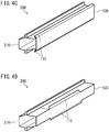
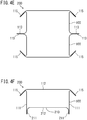
- FIG. 4A to FIG. 4H are views each of which schematically shows a cross section perpendicular to the longitudinal direction of the structural member (S).
- FIG. 4C and FIG. 4D are perspective views each of which schematically shows the structural member (S).
- Each of all structural members (S) shown in FIG. 4A to FIG. 4H has a closed cross section.
- a structural member 200 shown in FIG. 4A includes a press formed product 100 which includes projecting portions 115, and a member 210 (another member (M)) having a flat plate shape.
- the member 210 is fixed to two flange portions 113 of the press formed product 100 such that the press formed product 100 and the member 210 form a closed cross section.
- a structural member 200 shown in FIG. 4B includes a press formed product 100 which includes projecting portions 115, and another member 210.
- the member 210 is a member having a substantially hat shape in cross section, and includes two flange portions 213.
- the two flange portions 113 of the press formed product 100 are fixed to the two flange portions 213 of the member 210 such that the inside of the press formed product 100 and the inside of the member 210 oppose to each other.
- FIG. 4C is a perspective view showing one example of a structural member having the cross section shown in FIG. 4B
- FIG. 4D is a perspective view showing another example.
- the projecting portions 115 are formed over the entire structural member 200 in the longitudinal direction.
- the projecting portions 115 are only partially formed on the structural member 200 in the longitudinal direction.
- a structural member 200 shown in FIG. 4E includes two press formed products 100 each of which includes projecting portions 115. Flange portions 113 are fixed with each other such that the inside of one press formed product 100 and the inside of another press formed product 100 oppose to each other. Either one of the two press formed products 100 may be assumed as another member (M).
- a structural member 200 shown in FIG. 4F includes a press formed product 100 which includes projecting portions 115, and a member 210.
- the press formed product 100 includes two vertical wall portions 111 and a top plate portion 112 which connects the two vertical wall portions 111 with each other.
- the member 210 includes two vertical wall portions 211 and a top plate portion 212 which connects the two vertical wall portions 211 with each other.
- neither of the press formed product 100 nor the member 210 includes a flange portion.
- the vertical wall portions 111 of the press formed product 100 and the vertical wall portions 211 of the member 210 are fixed with each other such that the top plate portions have the same direction with respect to the vertical wall portions.
- a structural member 200 shown in FIG. 4G differs from the structural member 200 shown in FIG. 4F only with respect to the direction of fixing the member 210.
- vertical wall portions 111 of a press formed product 100 and vertical wall portions 211 of a member 210 are fixed with each other such that the inside of the press formed product 100 and the inside of the member 210 oppose to each other.
- a structural member 200 shown in FIG. 4H includes two press formed products 100 each of which includes projecting portions 115. Neither of the two press formed products 100 includes a flange portion. Vertical wall portions 111 of one press formed product 100 and vertical wall portions 111 of another press formed product 100 are fixed with each other such that the inside of the one press formed product 100 and the inside of another press formed product 100 oppose to each other.
- a method for producing the press formed product (P) according to the present invention is described.
- a preformed product is formed in a first step, and the preformed product is pressed in a second step.
- the press formed product (P) 100 of this embodiment can be produced.
- the second step is performed by hot stamping is described.
- a blank steel sheet is deformed so as to form a preformed product 301 which includes two portions (first portions) to be formed into two vertical wall portions 111, and a portion (second portion) to be formed into a top plate portion 112.
- the first step can be performed by the above-mentioned method (by pressing, for example).
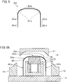
- FIG. 5 schematically shows a cross section (cross section perpendicular to the longitudinal direction) of one example of the preformed product 301 formed in the first step.
- the preformed product 301 has a substantially U shape in cross section (inverted in FIG. 5 ).
- the preformed product 301 includes two first portions 301a to be formed into the two vertical wall portions 111, and a second portion 301b to be formed into the top plate portion 112.
- the preformed product 301 further includes portions (surplus portions 301c) to be formed into projecting portions 115.
- FIG. 5 shows the case where the preformed product 301 includes third portions 301d to be formed into flange portions 113.
- a preformed product 301 includes no third portion 301d.
- the second step is performed by hot stamping.
- the preformed product 301 is heated to a temperature of the Ac3 transformation point or above (a temperature greater than the Ac3 transformation point by 80°C or greater, for example). This heating is performed by heating the preformed product 301 in a heater, for example.
- the heated preformed product 301 is pressed by a pressing device.
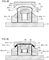
- a pressing device One example of the configuration of a press die used for pressing is shown in FIG. 6A .
- the pressing device includes a pair of press dies 10, a plate 13, and two slide dies 14.
- the pair of press dies 10 includes an upper die 11 (die) and a lower die 12 (punch).
- the lower die 12 includes a lower die body 12a and a pad 12b.
- the pad 12b is connected to the lower die body 12a via an extension and contraction mechanism 12c which can be extended and contracted.
- a known extension and contraction mechanism such as a spring or a hydraulic cylinder, may be used as the extension and contraction mechanism.
- the slide dies 14 slide on the plate 13 in the horizontal direction.
- the slide dies 14 may be caused to slide using a cam mechanism which moves with the movement of the press die 10.
- the slide dies 10 may be caused to slide using an actuator, such as a hydraulic cylinder.
- the preformed product 301 is set between the upper die 11 and the lower die 12.
- the slide dies 14 are caused to slide toward the lower die 12, thus constraining the two first portions 301a by the lower die 12 (lower die body 12a) and the slide dies 14 (step (i)).
- the first portions 301a are formed into the vertical wall portions 111.
- the second portion 301b and the surplus portions 301c can be freely deformed.
- the upper die 11 is moved downward so as to press the second portion 301b by the lower die 12 and the upper die 11, and so as to press the surplus portions 301c by the upper die 11 and the slide dies 14.
- the press formed product 100 is formed (step (ii)).
- the second portion 301b is sandwiched between the pad 12b and the upper die 11, and is moved downward while maintaining such a state and, then, reaches the upper surface of the lower die body 12a.
- the top plate portion 112 is formed.
- Each surplus portion 301c comes into contact with the upper die 11 and the slide die 14 with the downward movement of the upper die 11, thus being gradually bent and, then, being formed into two layers.
- the projecting portions 115 are formed each of which includes an overlapping portion, and projects obliquely downward.
- the press formed product 100 which includes the projecting portions 115 can be acquired in this manner.
- the heated preformed product 301 is cooled at the time of performing press forming so that press forming and quenching are performed.
- Each projecting portion 115 of the press formed product 100 projects obliquely downward. Accordingly, it is preferable to move the press formed product 100 upward before the slide dies 14 are returned to an original position. Specifically, first, as shown in FIG. 6D , after the step (ii) is performed, constraint of the vertical wall portions 111 performed by the lower die 12 and the slide dies 14 is released, and the upper die 11 and the pad 12b are moved upward, thus moving the press formed product 100 upward (step (iii)). At this point of operation, the press formed product 100 is moved upward such that the lower edges of the projecting portions 115 (distal end portions 115t) are positioned above the upper edges of the slide dies 14. Constraint of the vertical wall portions 111 can be released by slightly separating the slide dies 14 from the lower die 12.
- step (iii) the slide dies 14 are separated from the lower die 12 (step (iv)).
- the slide dies 14 are caused to slide such that the slide dies 14 are positioned further outward than the distal end portions 115t of the projecting portions 115.
- the press formed product 100 is taken out from the pressing device.
- FIG. 7A and FIG. 7B One example of a method for forming a flange portion is shown in FIG. 7A and FIG. 7B .
- a pressing device shown in FIG. 7A includes an upper die 21, a lower die 22, and a posture holding die 23.
- the upper die 21 includes a projecting portion 21a, a recessed portion 21b, a pad 21c, and an extension and contraction mechanism 21d.
- the pad 21c is connected to the recessed portion 21b by the extension and contraction mechanism 21d which can be extended and contracted.
- the press formed product 100 is set on the pressing device.
- the posture holding die 23 is provided for preventing the press formed product 100 from being inclined so that the posture holding die 23 does not constrain the press formed product 100.
- the upper die 21 is moved downward. With the downward movement of the upper die 21, first, a portion of the vertical wall portion 111 is fixed by the pad 21c and the lower die 22. When the upper die 21 is further moved downward, the extension and contraction mechanism 21d is constrained, and a third portion 301d which is contiguous from the vertical wall portion 111 is bent.
- One flange portion 113 is formed as described above. The other flange portion is formed in the same manner so that the press formed product (P) which includes two flange portions can be acquired.
- a simulation of a three-point bending test was performed on a structural member (S) with the press formed product (P) of this embodiment.
- a general-purpose FEM (finite element method) software made by LIVERMORE SOFTWARE TECHNOLOGY, trade name: LS-DYNA was used.
- FIG. 8A is a cross-sectional view schematically showing a sample 1 used in the simulation as a Comparative Example.
- the sample 1 shown in FIG. 8A is formed of two U-shaped members 31 and 32.
- Each of the U-shaped members 31 and 32 includes two vertical wall portions and a top plate portion which connects the two vertical wall portions.
- FIG. 8A it is assumed that the U-shaped member 31 and the U-shaped member 32 are joined by spot welding at fixing portions 33 of the vertical wall portions. Sizes of respective portions of the sample 1 are shown in FIG. 8A .
- the length of the sample 1 in the longitudinal direction is set to 800 mm.
- FIG. 8B is a cross-sectional view schematically showing a sample 2 used in the simulation as a reference example 1.
- the sample 2 shown in FIG. 8B includes a press formed product 100a and a member 210 having a U shape in cross section.
- the angle X is set to 180°.
- the press formed product 100a shown in FIG. 8B is different from the press formed product (P) of this embodiment.
- the press formed product 100a includes projecting portions 115. It is assumed that the press formed product 100a and the member 210 are joined by spot welding at fixing portions 211 of vertical wall portions 111.
- the shape of the sample 2 is as follows. Angle X: 180° Angle Y (see FIG.
- FIG. 8C , FIG. 8D, FIG. 8E, and FIG. 8F are cross-sectional views respectively showing projecting portions of the samples having the angle X of 202°, 225°, 247°, and 270°, and areas around the projecting portions.
- FIG. 8G is a cross-sectional view schematically showing a sample 3 used in the simulation as a reference example 2.
- a steel sheet is folded over into three layers at an upper edge portion of each vertical wall portion 111 so that portions which correspond to the projecting portions 115 are brought into close contact with the vertical wall portions 111. That is, portions which correspond to the projecting portions 115 do not substantially project from boundary portions each of which connects the vertical wall portion 111 and the top plate portion 112 with each other.
- the shape of the sample 3 other than the above-mentioned portions is equal to the shape of the sample 2.
- each of all samples is formed of a steel sheet having a thickness of 1.4 mm, and tensile strength of 1500 MPa. It is assumed that the press formed product and another member are fixed by spot welding at pitches of 40 mm.
- FIG. 9 A method of the three-point bending test used in the simulation is schematically shown in FIG. 9 .
- the three-point bending test was performed such that a sample is placed on two fulcrums 1, and the sample is pressed from above by an impactor 2.
- a distance S between the two fulcrums 1 was set to 400 mm or 700 mm.
- the radius of curvature of the fulcrum 1 was set to 50 mm.
- the radius of curvature of the impactor 2 was set to 150 mm.
- the collision speed of the impactor 2 was set to 7.2 km/h.
- the simulation was performed by taking into account spot welding and breaking off of material.
- the impactor 2 was caused to collide with each sample from above (from the top plate portion side).
- the collision direction of the impactor 2 is indicated by an arrow in FIG. 8A and FIG. 8B .
- FIG. 10 shows the results of the case where the distance S is set to 700 mm.
- FIG. 11 shows the results of the case where the distance S is set to 400 mm.
- the abscissa in FIG. 10 and FIG. 11 shows the amount of movement (amount of displacement) of the impactor 2 after the impactor 2 collides with the sample.
- the ordinate in FIG. 10 and FIG. 11 shows a load generated in the impactor 2.
- the ordinate in FIG. 12 shows the amount of energy absorption until the displacement amount reaches 60 mm.
- FIG. 13 shows a maximum load generated in the impactor 2. Both of FIG. 12 and FIG. 13 show the results of the case where the distance S is set to 700 mm.
- the sample of the Inventive Example of the present invention has higher characteristics than the Comparative Example (sample 1), the reference example 1 (sample 2), and the reference example 2 (sample 3).
- the Comparative Example (sample 1) and the reference example 2 (sample 3) have remarkably low characteristics.
- the distance S was set to 700 mm, and the displacement amount was set to 30 mm
- the vertical wall portions of the sample 1 were inclined outward.
- the vertical wall portions of the sample 3 were also inclined outward.
- this embodiment it is possible to acquire a structural member having high characteristics in the three-point bending test. With the use of the structural member of this embodiment, it is possible to improve collision safety of an automobile, and reduce the weight of an automobile.
- the present invention can be used for a press formed product, an automobile structural member with the press formed product, and a method for producing the press formed product.
Landscapes
- Engineering & Computer Science (AREA)
- Mechanical Engineering (AREA)
- Chemical & Material Sciences (AREA)
- Combustion & Propulsion (AREA)
- Transportation (AREA)
- Shaping Metal By Deep-Drawing, Or The Like (AREA)
- Body Structure For Vehicles (AREA)
- Mounting, Exchange, And Manufacturing Of Dies (AREA)
Applications Claiming Priority (2)
| Application Number | Priority Date | Filing Date | Title |
|---|---|---|---|
| JP2017077433 | 2017-04-10 | ||
| PCT/JP2018/015002 WO2018190320A1 (ja) | 2017-04-10 | 2018-04-10 | プレス成形品およびそれを用いた自動車用の構造部材、ならびにプレス成形品の製造方法 |
Publications (3)
| Publication Number | Publication Date |
|---|---|
| EP3610962A1 true EP3610962A1 (de) | 2020-02-19 |
| EP3610962A4 EP3610962A4 (de) | 2021-01-27 |
| EP3610962B1 EP3610962B1 (de) | 2025-08-20 |
Family
ID=63793691
Family Applications (1)
| Application Number | Title | Priority Date | Filing Date |
|---|---|---|---|
| EP18784833.8A Active EP3610962B1 (de) | 2017-04-10 | 2018-04-10 | Strukturelement für kraftfahrzeuge mit pressformkörper und herstellungsverfahren für strukturelement für kraftfahrzeuge |
Country Status (10)
| Country | Link |
|---|---|
| US (1) | US11534815B2 (de) |
| EP (1) | EP3610962B1 (de) |
| JP (1) | JP6769546B2 (de) |
| KR (2) | KR102379059B1 (de) |
| CN (1) | CN110475628B (de) |
| BR (1) | BR112019020366A2 (de) |
| CA (1) | CA3059161A1 (de) |
| MX (1) | MX2019012082A (de) |
| RU (1) | RU2019135689A (de) |
| WO (1) | WO2018190320A1 (de) |
Families Citing this family (7)
| Publication number | Priority date | Publication date | Assignee | Title |
|---|---|---|---|---|
| JP7288183B2 (ja) * | 2019-03-20 | 2023-06-07 | 日本製鉄株式会社 | 車体部材 |
| JP6760539B1 (ja) * | 2019-10-09 | 2020-09-23 | 日本製鉄株式会社 | 成形品およびそれを用いた構造部材、ならびに成形品の製造方法 |
| MX2022004499A (es) * | 2019-10-14 | 2022-05-06 | Autotech Eng Sl | Sistemas y metodos de prensado. |
| WO2023043135A1 (ko) * | 2021-09-14 | 2023-03-23 | 이효진 | 금속용기 드로잉 성형장치 및 방법 |
| CN116393586B (zh) * | 2023-06-07 | 2023-09-12 | 镇江先锋汽车零部件有限公司 | 一种电机外壳轴向双层叠料成型工艺 |
| CN121511187A (zh) * | 2023-07-19 | 2026-02-10 | 日本制铁株式会社 | A柱上部外构件、门环结构体和门环结构体的制造方法 |
| JPWO2025017990A1 (de) * | 2023-07-19 | 2025-01-23 |
Family Cites Families (19)
| Publication number | Priority date | Publication date | Assignee | Title |
|---|---|---|---|---|
| JPS5639698Y2 (de) * | 1975-10-01 | 1981-09-16 | ||
| JPS54119121U (de) * | 1978-02-07 | 1979-08-21 | ||
| JPS58209615A (ja) | 1982-05-28 | 1983-12-06 | Hashimoto Forming Co Ltd | 車輌用ドアサツシ要素の製造方法 |
| JPS6361627A (ja) * | 1986-09-01 | 1988-03-17 | Nissan Motor Co Ltd | 自動車用ドアガ−ドバ− |
| JP3452441B2 (ja) * | 1996-03-14 | 2003-09-29 | 住友金属工業株式会社 | 接合構造部材 |
| DE19756459A1 (de) * | 1997-11-25 | 1999-06-02 | Wagon Automotive Gmbh | Aufprallträger für eine Kraftfahrzeugtür |
| US7407219B2 (en) * | 2004-03-24 | 2008-08-05 | Shape Corporation | Energy management beam |
| KR100440161B1 (ko) * | 2002-06-28 | 2004-07-12 | 현대자동차주식회사 | 캠형 프레스 장치 |
| US7021099B2 (en) * | 2003-06-12 | 2006-04-04 | General Motors Corporation | Extraction system for hot formed parts |
| JP4973180B2 (ja) | 2006-12-22 | 2012-07-11 | 住友金属工業株式会社 | 衝撃吸収部材の製造方法 |
| JP4983373B2 (ja) | 2007-04-23 | 2012-07-25 | 住友金属工業株式会社 | 衝撃吸収部材及びその製造方法 |
| US8516874B2 (en) * | 2007-12-27 | 2013-08-27 | Toyota Motor Engineering & Manufacturing North America, Inc. | Pillar for motor vehicle and tool for making the same |
| JP2010242168A (ja) | 2009-04-06 | 2010-10-28 | Daihatsu Motor Co Ltd | 金属板の製造方法、金属板の補強方法および金属板 |
| JP2011067841A (ja) | 2009-09-25 | 2011-04-07 | Daihatsu Motor Co Ltd | 中空柱状部品の製造方法 |
| JP2011083807A (ja) | 2009-10-16 | 2011-04-28 | Daihatsu Motor Co Ltd | 断面ハット状部品の製造方法 |
| JP2012121377A (ja) * | 2010-12-06 | 2012-06-28 | Yorozu Corp | フレーム部材とその製造方法 |
| JP5835768B2 (ja) * | 2011-07-27 | 2015-12-24 | ダイハツ工業株式会社 | フレーム部品の製造方法 |
| JP6001884B2 (ja) * | 2012-03-09 | 2016-10-05 | 株式会社神戸製鋼所 | プレス成形品の製造方法およびプレス成形品 |
| EP2977120B8 (de) * | 2013-03-21 | 2018-07-25 | Nippon Steel & Sumitomo Metal Corporation | Verfahren zur herstellung eines pressgeformten teils und pressformvorrichtung |
-
2018
- 2018-04-10 KR KR1020217015179A patent/KR102379059B1/ko active Active
- 2018-04-10 US US16/498,238 patent/US11534815B2/en active Active
- 2018-04-10 RU RU2019135689A patent/RU2019135689A/ru not_active Application Discontinuation
- 2018-04-10 MX MX2019012082A patent/MX2019012082A/es unknown
- 2018-04-10 JP JP2019512513A patent/JP6769546B2/ja active Active
- 2018-04-10 WO PCT/JP2018/015002 patent/WO2018190320A1/ja not_active Ceased
- 2018-04-10 KR KR1020197032338A patent/KR102286789B1/ko active Active
- 2018-04-10 EP EP18784833.8A patent/EP3610962B1/de active Active
- 2018-04-10 CA CA3059161A patent/CA3059161A1/en not_active Abandoned
- 2018-04-10 CN CN201880023300.8A patent/CN110475628B/zh active Active
- 2018-04-10 BR BR112019020366A patent/BR112019020366A2/pt not_active Application Discontinuation
Also Published As
| Publication number | Publication date |
|---|---|
| JPWO2018190320A1 (ja) | 2020-05-14 |
| KR102286789B1 (ko) | 2021-08-06 |
| EP3610962A4 (de) | 2021-01-27 |
| WO2018190320A1 (ja) | 2018-10-18 |
| US11534815B2 (en) | 2022-12-27 |
| CN110475628A (zh) | 2019-11-19 |
| KR102379059B1 (ko) | 2022-03-28 |
| RU2019135689A (ru) | 2021-05-11 |
| EP3610962B1 (de) | 2025-08-20 |
| CN110475628B (zh) | 2022-02-01 |
| US20200038934A1 (en) | 2020-02-06 |
| JP6769546B2 (ja) | 2020-10-14 |
| CA3059161A1 (en) | 2018-10-18 |
| BR112019020366A2 (pt) | 2020-04-28 |
| KR20190131566A (ko) | 2019-11-26 |
| RU2019135689A3 (de) | 2021-05-11 |
| MX2019012082A (es) | 2019-11-11 |
| KR20210060673A (ko) | 2021-05-26 |
Similar Documents
| Publication | Publication Date | Title |
|---|---|---|
| EP3610962B1 (de) | Strukturelement für kraftfahrzeuge mit pressformkörper und herstellungsverfahren für strukturelement für kraftfahrzeuge | |
| EP3485996B1 (de) | Heissgestanztes artikel, strukturelles element mit verwendung davon und verfahren zur herstellung eines heissgestanzten artikel | |
| US11097789B2 (en) | Structural member for automobiles and method for producing the same | |
| US10239105B2 (en) | Blank steel plate, production method and production device therefor, and production method for press-formed product using blank steel plate | |
| EP3485995B1 (de) | Heissgestanztes formprodukt, automobilteil und verfahren zur herstellung eines heissgestanzten formprodukts | |
| KR102730155B1 (ko) | 성형품 및 그것을 사용한 구조 부재, 그리고 성형품의 제조 방법 | |
| JP7155923B2 (ja) | 成形品の製造方法 | |
| CN114585456A (zh) | 成型品的制造方法、成型品以及使用其的构造部件 |
Legal Events
| Date | Code | Title | Description |
|---|---|---|---|
| STAA | Information on the status of an ep patent application or granted ep patent |
Free format text: STATUS: THE INTERNATIONAL PUBLICATION HAS BEEN MADE |
|
| PUAI | Public reference made under article 153(3) epc to a published international application that has entered the european phase |
Free format text: ORIGINAL CODE: 0009012 |
|
| STAA | Information on the status of an ep patent application or granted ep patent |
Free format text: STATUS: REQUEST FOR EXAMINATION WAS MADE |
|
| 17P | Request for examination filed |
Effective date: 20190927 |
|
| AK | Designated contracting states |
Kind code of ref document: A1 Designated state(s): AL AT BE BG CH CY CZ DE DK EE ES FI FR GB GR HR HU IE IS IT LI LT LU LV MC MK MT NL NO PL PT RO RS SE SI SK SM TR |
|
| AX | Request for extension of the european patent |
Extension state: BA ME |
|
| DAV | Request for validation of the european patent (deleted) | ||
| DAX | Request for extension of the european patent (deleted) | ||
| A4 | Supplementary search report drawn up and despatched |
Effective date: 20210111 |
|
| RIC1 | Information provided on ipc code assigned before grant |
Ipc: B21D 24/00 20060101ALI20201218BHEP Ipc: B21D 22/20 20060101ALI20201218BHEP Ipc: B62D 25/20 20060101ALI20201218BHEP Ipc: B62D 25/06 20060101ALI20201218BHEP Ipc: B62D 25/04 20060101ALI20201218BHEP Ipc: B21D 22/26 20060101AFI20201218BHEP Ipc: B21D 37/08 20060101ALI20201218BHEP |
|
| STAA | Information on the status of an ep patent application or granted ep patent |
Free format text: STATUS: EXAMINATION IS IN PROGRESS |
|
| 17Q | First examination report despatched |
Effective date: 20240411 |
|
| GRAP | Despatch of communication of intention to grant a patent |
Free format text: ORIGINAL CODE: EPIDOSNIGR1 |
|
| STAA | Information on the status of an ep patent application or granted ep patent |
Free format text: STATUS: GRANT OF PATENT IS INTENDED |
|
| INTG | Intention to grant announced |
Effective date: 20250522 |
|
| GRAS | Grant fee paid |
Free format text: ORIGINAL CODE: EPIDOSNIGR3 |
|
| GRAA | (expected) grant |
Free format text: ORIGINAL CODE: 0009210 |
|
| STAA | Information on the status of an ep patent application or granted ep patent |
Free format text: STATUS: THE PATENT HAS BEEN GRANTED |
|
| AK | Designated contracting states |
Kind code of ref document: B1 Designated state(s): AL AT BE BG CH CY CZ DE DK EE ES FI FR GB GR HR HU IE IS IT LI LT LU LV MC MK MT NL NO PL PT RO RS SE SI SK SM TR |
|
| REG | Reference to a national code |
Ref country code: GB Ref legal event code: FG4D |
|
| REG | Reference to a national code |
Ref country code: CH Ref legal event code: EP |
|
| REG | Reference to a national code |
Ref country code: IE Ref legal event code: FG4D |
|
| REG | Reference to a national code |
Ref country code: DE Ref legal event code: R096 Ref document number: 602018084777 Country of ref document: DE |
|
| REG | Reference to a national code |
Ref country code: NL Ref legal event code: MP Effective date: 20250820 |
|
| PG25 | Lapsed in a contracting state [announced via postgrant information from national office to epo] |
Ref country code: IS Free format text: LAPSE BECAUSE OF FAILURE TO SUBMIT A TRANSLATION OF THE DESCRIPTION OR TO PAY THE FEE WITHIN THE PRESCRIBED TIME-LIMIT Effective date: 20251220 |
|
| PG25 | Lapsed in a contracting state [announced via postgrant information from national office to epo] |
Ref country code: NO Free format text: LAPSE BECAUSE OF FAILURE TO SUBMIT A TRANSLATION OF THE DESCRIPTION OR TO PAY THE FEE WITHIN THE PRESCRIBED TIME-LIMIT Effective date: 20251120 |
|
| REG | Reference to a national code |
Ref country code: LT Ref legal event code: MG9D |
|
| PG25 | Lapsed in a contracting state [announced via postgrant information from national office to epo] |
Ref country code: PT Free format text: LAPSE BECAUSE OF FAILURE TO SUBMIT A TRANSLATION OF THE DESCRIPTION OR TO PAY THE FEE WITHIN THE PRESCRIBED TIME-LIMIT Effective date: 20251222 |
|
| PG25 | Lapsed in a contracting state [announced via postgrant information from national office to epo] |
Ref country code: FI Free format text: LAPSE BECAUSE OF FAILURE TO SUBMIT A TRANSLATION OF THE DESCRIPTION OR TO PAY THE FEE WITHIN THE PRESCRIBED TIME-LIMIT Effective date: 20250820 |
|
| PG25 | Lapsed in a contracting state [announced via postgrant information from national office to epo] |
Ref country code: NL Free format text: LAPSE BECAUSE OF FAILURE TO SUBMIT A TRANSLATION OF THE DESCRIPTION OR TO PAY THE FEE WITHIN THE PRESCRIBED TIME-LIMIT Effective date: 20250820 Ref country code: HR Free format text: LAPSE BECAUSE OF FAILURE TO SUBMIT A TRANSLATION OF THE DESCRIPTION OR TO PAY THE FEE WITHIN THE PRESCRIBED TIME-LIMIT Effective date: 20250820 |
|
| PG25 | Lapsed in a contracting state [announced via postgrant information from national office to epo] |
Ref country code: GR Free format text: LAPSE BECAUSE OF FAILURE TO SUBMIT A TRANSLATION OF THE DESCRIPTION OR TO PAY THE FEE WITHIN THE PRESCRIBED TIME-LIMIT Effective date: 20251121 |
|
| PG25 | Lapsed in a contracting state [announced via postgrant information from national office to epo] |
Ref country code: SE Free format text: LAPSE BECAUSE OF FAILURE TO SUBMIT A TRANSLATION OF THE DESCRIPTION OR TO PAY THE FEE WITHIN THE PRESCRIBED TIME-LIMIT Effective date: 20250820 |
|
| PG25 | Lapsed in a contracting state [announced via postgrant information from national office to epo] |
Ref country code: LV Free format text: LAPSE BECAUSE OF FAILURE TO SUBMIT A TRANSLATION OF THE DESCRIPTION OR TO PAY THE FEE WITHIN THE PRESCRIBED TIME-LIMIT Effective date: 20250820 |
|
| PG25 | Lapsed in a contracting state [announced via postgrant information from national office to epo] |
Ref country code: PL Free format text: LAPSE BECAUSE OF FAILURE TO SUBMIT A TRANSLATION OF THE DESCRIPTION OR TO PAY THE FEE WITHIN THE PRESCRIBED TIME-LIMIT Effective date: 20250820 Ref country code: BG Free format text: LAPSE BECAUSE OF FAILURE TO SUBMIT A TRANSLATION OF THE DESCRIPTION OR TO PAY THE FEE WITHIN THE PRESCRIBED TIME-LIMIT Effective date: 20250820 |
|
| PG25 | Lapsed in a contracting state [announced via postgrant information from national office to epo] |
Ref country code: RS Free format text: LAPSE BECAUSE OF FAILURE TO SUBMIT A TRANSLATION OF THE DESCRIPTION OR TO PAY THE FEE WITHIN THE PRESCRIBED TIME-LIMIT Effective date: 20251120 |
|
| PG25 | Lapsed in a contracting state [announced via postgrant information from national office to epo] |
Ref country code: ES Free format text: LAPSE BECAUSE OF FAILURE TO SUBMIT A TRANSLATION OF THE DESCRIPTION OR TO PAY THE FEE WITHIN THE PRESCRIBED TIME-LIMIT Effective date: 20250820 |
|
| REG | Reference to a national code |
Ref country code: AT Ref legal event code: MK05 Ref document number: 1826796 Country of ref document: AT Kind code of ref document: T Effective date: 20250820 |
|
| PG25 | Lapsed in a contracting state [announced via postgrant information from national office to epo] |
Ref country code: SM Free format text: LAPSE BECAUSE OF FAILURE TO SUBMIT A TRANSLATION OF THE DESCRIPTION OR TO PAY THE FEE WITHIN THE PRESCRIBED TIME-LIMIT Effective date: 20250820 |
|
| PG25 | Lapsed in a contracting state [announced via postgrant information from national office to epo] |
Ref country code: DK Free format text: LAPSE BECAUSE OF FAILURE TO SUBMIT A TRANSLATION OF THE DESCRIPTION OR TO PAY THE FEE WITHIN THE PRESCRIBED TIME-LIMIT Effective date: 20250820 |
|
| PG25 | Lapsed in a contracting state [announced via postgrant information from national office to epo] |
Ref country code: AT Free format text: LAPSE BECAUSE OF FAILURE TO SUBMIT A TRANSLATION OF THE DESCRIPTION OR TO PAY THE FEE WITHIN THE PRESCRIBED TIME-LIMIT Effective date: 20250820 |
|
| PG25 | Lapsed in a contracting state [announced via postgrant information from national office to epo] |
Ref country code: IT Free format text: LAPSE BECAUSE OF FAILURE TO SUBMIT A TRANSLATION OF THE DESCRIPTION OR TO PAY THE FEE WITHIN THE PRESCRIBED TIME-LIMIT Effective date: 20250820 |
|
| PG25 | Lapsed in a contracting state [announced via postgrant information from national office to epo] |
Ref country code: CZ Free format text: LAPSE BECAUSE OF FAILURE TO SUBMIT A TRANSLATION OF THE DESCRIPTION OR TO PAY THE FEE WITHIN THE PRESCRIBED TIME-LIMIT Effective date: 20250820 |
|
| PG25 | Lapsed in a contracting state [announced via postgrant information from national office to epo] |
Ref country code: SK Free format text: LAPSE BECAUSE OF FAILURE TO SUBMIT A TRANSLATION OF THE DESCRIPTION OR TO PAY THE FEE WITHIN THE PRESCRIBED TIME-LIMIT Effective date: 20250820 Ref country code: EE Free format text: LAPSE BECAUSE OF FAILURE TO SUBMIT A TRANSLATION OF THE DESCRIPTION OR TO PAY THE FEE WITHIN THE PRESCRIBED TIME-LIMIT Effective date: 20250820 |