EP3612054B1 - Procédé et dispositif destinés à fabriquer des brosses - Google Patents
Procédé et dispositif destinés à fabriquer des brosses Download PDFInfo
- Publication number
- EP3612054B1 EP3612054B1 EP18718127.6A EP18718127A EP3612054B1 EP 3612054 B1 EP3612054 B1 EP 3612054B1 EP 18718127 A EP18718127 A EP 18718127A EP 3612054 B1 EP3612054 B1 EP 3612054B1
- Authority
- EP
- European Patent Office
- Prior art keywords
- chain
- processing station
- processing
- tool
- bristle
- Prior art date
- Legal status (The legal status is an assumption and is not a legal conclusion. Google has not performed a legal analysis and makes no representation as to the accuracy of the status listed.)
- Active
Links
Images


Classifications
-
- A—HUMAN NECESSITIES
- A46—BRUSHWARE
- A46D—MANUFACTURE OF BRUSHES
- A46D3/00—Preparing, i.e. Manufacturing brush bodies
- A46D3/06—Machines for both drilling bodies and inserting bristles
- A46D3/065—Machines for both drilling bodies and inserting bristles of the belt or chain type
-
- A—HUMAN NECESSITIES
- A46—BRUSHWARE
- A46D—MANUFACTURE OF BRUSHES
- A46D3/00—Preparing, i.e. Manufacturing brush bodies
- A46D3/04—Machines for inserting or fixing bristles in bodies
-
- A—HUMAN NECESSITIES
- A46—BRUSHWARE
- A46D—MANUFACTURE OF BRUSHES
- A46D3/00—Preparing, i.e. Manufacturing brush bodies
- A46D3/08—Parts of brush-making machines
- A46D3/087—Holders or supports for brush bodies
Definitions
- the invention relates to a method and a device for producing brushes which have a bristle carrier in which one or more bristles are fixed.
- Such a device is, for example, from DE 196 34 278 A1 or the EP 0 563 419 B1 known. What these known methods and devices have in common is that the bristle carriers are moved along a revolving path on holders that are fastened to chain links of an endless chain. One or more processing stations are present along this path, through which the bristle carriers are transported and processed along the way. Such processing stations include, for example, stuffing, cutting off bristles or rounding off bristles. However, this list is not final.
- the bristle carriers are clocked into the processing stations step by step and then guided out of the processing station again via the chain in the direction of the next processing station. In the processing station, the bristle carriers usually have to be aligned in two directions that intersect if this alignment does not take place by aligning the processing tool.
- tamping station in which a tamping tool is moved along a linear or slightly curved path with individual bristles or bristle tufts against the bristle carrier in order to push the bristle or bristle tuft into corresponding openings in the bristle carrier.
- the bristle heads are realigned in two directions in order to align a free opening with the tamping tool. There are several options for this alignment.
- the DE 196 34 278 A1 proposes bringing about the orientation in the direction of rotation by moving the chain links and the orientation at right angles thereto by a relative movement of the holder on the associated chain links.
- the holders have a longitudinal guide transverse to the direction of rotation, in which the holders are moved.
- a brush manufacturing machine which has a spatially curved guide track in several directions. Corresponding curves run vertically but also horizontally in order to make the overall length of the brush manufacturing machine as small as possible and the transport device as compact as possible.
- a chain consisting of several chain elements is guided in the guide track, on which holders for brush bodies are attached.
- the individual chain links are connected to each other via a cardan joint in order to enable the relative movement of the chain links in many spatial directions.
- the DE 10 2013 103 903 A1 also relates to a brush manufacturing machine having a track along which brush bodies are moved. Segments can be decoupled from the guide track relative to the rest of the guide track in order to move holders for brush bodies, which are moved along this guide track, in different directions during the tamping process.
- the object of the invention is to develop a method and a device that allow a simple, inexpensive construction of the device, with the method being reliable and simple.
- the holder on which the processing is currently taking place is not decoupled from the chain link in any direction, nor is the chain link to be aligned decoupled from the rest of the chain. Rather, the entire chain link located in the processing station, including adjacent chain links, is aligned so that less effort is required for positioning the bristle carrier in the processing station.
- the chain and holder can be designed simply. Individual guides between the chain link, holder and/or bristle carrier are no longer necessary.
- the processing tool can carry out several processing actions in which the bristle carrier to be processed is positioned differently from the processing tool, the different positions being approached by the positioning device by moving the chain link in two directions.
- An example of such a processing tool is a tamping tool with individual tamping strokes between which the bristle carrier has to be repositioned.
- the chain In order to align the bristle carrier in the processing station in a direction transverse to the direction of rotation of the chain, the chain is moved laterally over several chain links, beginning in front of the processing station pivoted. In order to realize the movement transverse to the direction of rotation, not only the chain link, which is located in the processing station, is moved laterally, but rather an entire section of the chain is pivoted laterally, so that the mobility of individual chain links relative to each other must be less than in the case that only the chain link located in the processing station is moved laterally to the rest of the chain.
- the chain can be folded in sections before and/or after the processing station to produce an excess chain length. When aligning the chain link in the direction of rotation, the folding is then enlarged and/or reduced. If the endless chain were tensioned between two sprockets, resulting in a kind of oval, all chain links of the chain would have to be moved as well for the rapid movement in the direction of rotation of the chain link in the processing station, since the chain is tensioned. On the one hand, this is disadvantageous due to the inertial mass of the entire chain and, moreover, the entire chain would be moved back and forth permanently in the direction of rotation, so that a separate alignment of the chain in another processing station would no longer be possible.
- the processing station is in particular a tamping station in which a tamping tool pushes at least one bristle, in particular several tufts of bristles, into associated openings in the bristle carrier.
- the bristle carrier is then positioned between the individual stuffing strokes by aligning the chain link.
- the tufting tool can only be moved back and forth against the bristle carrier along a fixed path of movement. This means the tamping tool itself is not oriented in multiple directions. Rather, the alignment takes place via the bristle carrier.
- the bristle carrier is shifted laterally between the individual movement cycles by the positioning device in order to align another opening for stuffing with the stuffing tool.
- the object mentioned above is also achieved by a device for producing brushes which have a bristle carrier in which one or more bristles are fixed.
- the device according to the invention comprises a revolving, endless chain with individual chain links pivotably attached to one another, on which holders for holding bristle carriers are provided, at least one processing station for carrying out at least one manufacturing step of the brush along the chain, with a processing tool for the bristle carrier in the processing station is available.
- the device comprises a positioning device in the processing station, which is coupled to the chain link located in the processing station.
- the positioning device can align the chain link in at least two intersecting directions, with the positioning device and the processing tool being controlled in such a way that the positioning device aligns the chain link and thus the bristle base to be processed relative to the processing tool for the subsequent processing step before processing.
- the device according to the invention is intended in particular for carrying out the method according to the invention and provides that the positioning device aligns the chain link in two directions and not just the holder on the chain link. After the adjacent chain links are coupled unchanged to the chain link to be aligned, the adjacent chain links are also moved when aligning the chain link located in the processing station.
- the chain is preferably mounted in such a way that it can pivot several chain links laterally in front of the processing station in a direction transverse to the direction of rotation of the chain.
- the chain has a track guide, the track guide having a rigid portion over which the chain is laterally positioned remote from the work station.
- the chain is laterally movable, in particular pivotable, between the rigid section and the processing station.
- the chain should therefore not be laterally shifted and pivoted over a large part of the chain length, but only in a relatively short section in front of the machining tool.
- the chain is precisely guided laterally, so that the holders are fitted with the bristle carriers here, for example or the bristle bases can be removed from the holders or other processing operations can be carried out, such as rounding off or cutting the bristle ends.
- Exact alignment of the movable part of the chain can be facilitated by the web guide having a pivoting section between the rigid section and the processing station, in which the chain is held transversely to the direction of rotation and is movable together with the pivoting section.
- This pivotable section of the track guide relieves the joints between adjacent chain links.
- the pivotable section is moved passively laterally, possibly also in the second direction.
- the processing station can be a tamping station with a tamping tool, the tamping tool preferably being moved against a sprocket.
- the sprocket can thus directly absorb the forces from the tufting tool, so that the bristle carrier is held stably and the entire holding system is little or not at all flexible.
- the chain runs over at least one sprocket in the processing station.
- the positioning device acts on the sprocket and moves it and thus the chain in two directions. This means that the chain itself is positioned very precisely, because the sprocket engages with the chain in a form-fitting manner.
- the sprocket is in particular a driven sprocket.
- a sprocket can act on opposite outer sides of the chain, with the two sprockets being rotationally coupled to one another. This means that the chain link located in the processing station is held directly on the sprocket at its two outer ends as viewed in the directions of circulation.
- pivotable section of the web guide runs between the rigid section and the positionable chain wheel.
- a simple configuration of the positioning device is an X-Y carriage, which can be a cheap purchased part and, for example, comprises two electric motors, in particular servomotors, that can be moved in two vertical directions.
- the drive of the sprocket is preferably seated on such an X-Y carriage so that the sprocket and drive are moved together.
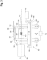
- a device for manufacturing brushes which comprises a number of stations, namely a feed station 10 for bristle carriers 12 (see FIG figure 2 ), a tamping station 14 with a tamping tool 16 in which the bristle carrier is stuffed with tufts of bristles, a shearing station 18 in which the free ends of the tufts of bristles are cut off, and a subsequent rounding station 20 in which the free ends of the bristle tufts that have been cut are rounded off .
- the processing tools are consequently stuffing tools, cutting tools and rounding tools.
- a removal station 22 is also provided, in which the finished brushes 24 are removed from the device.
- the bristle carriers 12 are transported through the stations and partly in the stations by a driven, revolving, endless chain 26, see FIG figure 2 , with chain links 28 arranged one behind the other and pivotably attached to one another, of which only two chain links are shown in figure 2 are provided with reference symbols.
- Holders 30 are seated on the chain links 28 and have corresponding holding feet or recesses in order to accommodate and fix the bristle carriers 12 .
- the holders 30 can be an integral part of the chain links 28 or, for example, can be fastened to the outside of the chain links 28 by a type of quick-release fastener.
- the attachment of separate holders 30 to the chain links 28 has the advantage that the device can be converted very quickly if other shapes of bristle carriers 12 are to be processed in the device.
- the holders 30 are fixedly mounted on the chain links 28, i. H. they are not slidable relative to their associated chain links 28 on which they are mounted during the process described below.
- the sprocket wheel 32 has two side gears 33 which are fixed to a common drive shaft 35 which in turn is driven by a drive motor 36, in particular in the form of an index motor.
- the chain 26 is held between the gears 33 laterally.
- Adjacent chain links 28, see figure 1 are connected to each other by a joint 38 which protrudes laterally opposite the chain links.
- the gear wheels 33 have recesses 41 on their circumference (see figure 1 ), which receive the joints 38 and thus transport the chain in the direction of rotation U intermittently.
- the chain 26 is guided in a track guide 40 in the area of the joints 38, namely how figure 2 shows, by two lateral, z. B. U-shaped rails 42. Between these rails 42, the chain can at most be minimally moved transversely to the direction of rotation U, so that it is very well guided laterally.
- the web guide 40 has based on the figure 1 upper strand of the chain 26 and for the lower strand in each case a rigid section 44.
- the chain as previously explained, can hardly deviate laterally in order to be guided perfectly in this direction.
- the rigid section 44 does not extend over the entire length between the two sprockets 32, 34, but extends from the sprocket 34 to a point 50 which ends several chain links 28 in front of the sprocket 32.
- a pivotable section 52 of the web guide 40 connects to the respective rigid section 44 for the upper and for the lower run.
- the movable sections 52 can preferably be pivoted via a bearing or joint 54 in the area of the transition to the respective rigid section 44, as indicated by the double arrow in FIG figure 2 shown.
- the respective pivotable section 52 can also be moved minimally in the vertical direction in a pivotable manner about bearing 56 .
- the tamping station 14 which represents a processing station, there is a positioning device 60 (see figure 3 ) available, via which the chain wheel 32 can be adjusted in two mutually perpendicular directions X and Y.
- the X direction is the direction transverse to the circumferential direction U and the Y direction is perpendicular thereto and preferably vertical.
- the chain is moved from the point 50 together with the pivotable section 52 of the web guide to open openings 62 (see Fig figure 3 ) in the bristle carrier 12, which is about to be stuffed with tufts of bristles, in this direction to the stuffing tool 16.
- the tamping tool 16 can only perform a reciprocating infeed movement in the Z direction (see figure 2 ).
- Axis Z is oriented to intersect central axis A of drive shaft 35 (see Fig figure 3 ).
- the drive motor 36 together with the chain wheel 32 is seated on an XY carriage 63 which has a base 64 on which is seated a carriage 66 which is movable along a guide 68 in the X direction by a motor 70, in particular a servo motor.
- the base 64 can be aligned vertically via guides 72 thereover.
- a drive motor 74 then moves the base 64 vertically in the Y direction.
- Motor 74 is also preferably a servo motor.
- the movement of the bristle carrier 12 in the Y-direction can also be effected by the motor 36 of the chain, in which case, however, it is then necessary for the chain to be accommodated between the gear wheels 33 without play.
- the guides 72 and the motor 74 are omitted.
- the chain 26 can optionally be folded, for example, shortly before and after the chain wheel 32, i.e. both on the upper and on the lower strand, as in Figure 1a , shown above.
- the fold bears the reference number 78.
- This additional length of the chain 26 gained by the fold 78 allows it to be moved more easily in the Y-direction by the positioning device and is decoupled from the rest of the chain in this area.
- the fold can be produced, for example, by an additional chain wheel 80 which begins after the pivotable section 52 of the web guide 40 .
- the fold can be outwards, as in Figure 1a , run or inwards towards the other strand.
- the bristle carriers 12 are slipped onto the corresponding holders 30 so that they sit on the holders 30 without play, with the openings 62, for example previously produced, pointing upwards.
- the chain 26 is driven by the motor 36 in a fixed cycle.
- a bristle carrier 12 As soon as a bristle carrier 12 has reached the tufting station 14, it is tufted with a plurality of tufts of bristles by the tufting tool 16, with figure 2 corresponding magazines 84 with differently colored bristles are shown, as is a so-called tuft separator 86.
- the tufting tool 16 can be a conventional tufting tool, which is moved back and forth along the Z direction or along a trajectory and always picks up a tuft of bristles and places it in the corresponding opening 62, which is aligned straight towards the tamping tool 16. It can be stuffed with or without an anchor.
- the positioning device 60 is used to align the bristle carrier 12 to be processed in the X and Y directions during the individual tufting strokes.
- the corresponding bristle carrier is then indexed further until it comes to the shearing station 18 where the bristle ends are trimmed and then rounded off in the rounding station 20 .
- the stations 18 and 20 can also be omitted if, for example, the bristles are not fixed in the corresponding opening 62 by an anchor, but their ends are first fused by heating in order to then be overmoulded.
- holders 30 for several bristle carriers 12 can be used on individual chain links 28 .
- a chain link 28 located in the tufting station 14 is positioned in the device in the X and Y directions, and the holder 30 is thus positioned on this chain link 28 together with the bristle carrier(s) 12 located thereon for processing positioned.
- the point 50 is about one meter away from the chain wheel 32.
Landscapes
- Engineering & Computer Science (AREA)
- Manufacturing & Machinery (AREA)
- Brushes (AREA)
- Physical Water Treatments (AREA)
- Seasonings (AREA)
- Distillation Of Fermentation Liquor, Processing Of Alcohols, Vinegar And Beer (AREA)
Claims (15)
- Procédé de fabrication de brosses (24) présentant un support de poils (12) dans lequel sont fixés un ou plusieurs poils, caractérisé par les étapes suivantes :le fournissement d'une chaîne sans fin circonférentielle (26) présentant des éléments de chaîne (28) individuels fixés de manière pivotante les uns aux autres et sur lesquels il est prévu des moyens de retenue (30) pour la retenue des supports de poils (12),le fournissement d'au moins une station de traitement pour la réalisation d'au moins une étape de fabrication de la brosse le long de la chaîne (26), un outil de traitement se trouvant dans la station de traitement,le fournissement d'un moyen de positionnement (60) à l'aide duquel les supports de poils (12) sont aptes à être alignés dans au moins deux sens qui se coupent sur leurs moyens de retenue (30) associés dans la station de traitement,l'avancement cadencé de la chaîne (26) avec les moyens de retenue (30) et les supports de poils (12) fixés sur ceux-ci jusque dans la station de traitement,l'alignement de l'élément de chaîne (28) se trouvant dans la station de traitement dans les deux sens à l'aide du moyen de positionnement (60), et ainsi l'alignement du support de poils (12) par rapport à l'outil de traitement, etla réalisation d'au moins une étape de traitement par l'outil de traitement.
- Procédé selon la revendication 1, caractérisé en ce que l'outil de traitement réalise plusieurs actions de traitement lors desquelles le support de poils (12) à traiter est positionné différemment par rapport à l'outil de traitement, les différentes positions étant atteintes par le moyen de positionnement (60) par un déplacement de l'élément de chaîne (28) dans les deux sens.
- Procédé selon la revendication 1 ou 2, caractérisé en ce que pour l'alignement du support de poils (12) dans la station de traitement (14) dans un sens perpendiculaire au sens périphérique (U) de la chaîne (26), la chaîne (26) est pivotée latéralement sur plusieurs éléments de chaîne (28) en commençant avant la station de traitement.
- Procédé selon l'une des revendications précédentes, caractérisé en ce que la chaîne (26) est pliée par tronçons avant et après la station de traitement pour produire une surlongueur de chaîne, et en ce que le pli (78) est agrandi et/ou diminué lors de l'alignement de l'élément de chaîne dans le sens périphérique (U).
- Procédé selon l'une des revendications précédentes, caractérisé en ce que la station de traitement est une station de bourrage (14) dans laquelle un outil de bourrage (16) pousse au moins un poil, en particulier plusieurs touffes de poils dans des orifices associés (62) dans le support de poils (12).
- Procédé selon la revendication 5, caractérisé en ce que l'outil de bourrage (16) est déplacé dans un mouvement de va-et-vient le long d'une trajectoire de déplacement prédéfinie de manière fixe contre le support de poils (12), et en ce que le support de poils (12) est déplacé latéralement par le moyen de positionnement (60) entre les cadences de déplacement individuelles pour aligner un autre orifice (62) pour le bourrage par rapport à l'outil de bourrage (16).
- Dispositif de fabrication de brosses (24) présentant un support de poils (12) dans lequel sont fixés un ou plusieurs poils, comprenant une chaîne sans fin circonférentielle (26) présentant des éléments de chaîne (28) individuels fixés de manière pivotante les uns aux autres et sur lesquels il est prévu des moyens de retenue (30) pour la retenue de supports de poils (12), au moins une station de traitement pour la réalisation d'au moins une étape de fabrication de la brosse le long de la chaîne (26), un outil de traitement pour le support de poils (12) se trouvant dans la station de traitement, un moyen de positionnement (60) dans la station de traitement qui est couplé à l'élément de chaîne (28) se trouvant respectivement dans la station de traitement et qui est apte à aligner l'élément de chaîne (28) dans au moins deux sens qui se coupent, le moyen de positionnement (60) et l'outil de traitement étant commandés de sorte que le moyen de positionnement (60), avant le traitement, aligne l'élément de chaîne (28) et ainsi le support de poils (12) à traiter par rapport à l'outil de traitement pour l'étape de traitement subséquente.
- Dispositif selon la revendication 7, caractérisé en ce que la chaîne (26) est montée de manière à pivoter latéralement plusieurs éléments de chaîne (28) dans un sens perpendiculaire au sens périphérique (U) de la chaîne (26) avant la station de traitement.
- Dispositif selon la revendication 8, caractérisé en ce que la chaîne (26) présente un guidage de trajectoire (40), le guidage de trajectoire (40) présentant un tronçon rigide (44) au moyen duquel la chaîne (26) est positionnée latéralement à distance de la station de traitement, et en ce que la chaîne (26) est mobile et est en particulier pivotante latéralement entre le tronçon rigide (44) et la station de traitement.
- Dispositif selon la revendication 9, caractérisé en ce que le guidage de trajectoire (40) présente un tronçon pivotant (52) entre le tronçon rigide (44) et la station de traitement dans lequel la chaîne (26) est maintenue perpendiculairement au sens périphérique (U) et est mobile ensemble avec le tronçon pivotant.
- Dispositif selon l'une des revendications 7 à 10, caractérisé en ce que dans la station de traitement, la chaîne (26) passe sur au moins une roue dentée à chaîne (32) et en ce que le moyen de positionnement (60) s'engage sur la roue dentée à chaîne (32) et déplace celle-ci et ainsi la chaîne (26) dans les deux sens.
- Dispositif selon la revendication 11, caractérisé en ce que la roue dentée à chaîne (32) est entraînée.
- Dispositif selon la revendication 10 et aussi selon la revendication 11 ou 12, caractérisé en ce que le tronçon pivotant (52) du guidage de trajectoire (40) s'étend entre le tronçon rigide (44) et la roue dentée à chaîne (32) positionnable.
- Dispositif selon l'une des revendications 7 à 14, caractérisé en ce que le moyen de positionnement (60) est un chariot à mouvement X-Y, en particulier en ce que la roue dentée à chaîne (32) est agencée sur le chariot à mouvement X-Y ensemble avec son entraînement.
- Dispositif selon l'une des revendications 7 à 14, caractérisé en ce que la station de traitement est une station de bourrage (14) qui comprend un outil de bourrage (16), l'outil de bourrage (16) étant en particulier déplacé contre la roue dentée à chaîne (32) positionnable.
Applications Claiming Priority (2)
| Application Number | Priority Date | Filing Date | Title |
|---|---|---|---|
| BE2017/5279A BE1024675B1 (de) | 2017-04-21 | 2017-04-21 | Verfahren und Vorrichtung zum Herstellen von Bürsten |
| PCT/EP2018/059235 WO2018192811A1 (fr) | 2017-04-21 | 2018-04-11 | Procédé et dispositif destinés à fabriquer des brosses |
Publications (2)
| Publication Number | Publication Date |
|---|---|
| EP3612054A1 EP3612054A1 (fr) | 2020-02-26 |
| EP3612054B1 true EP3612054B1 (fr) | 2023-07-05 |
Family
ID=58692243
Family Applications (1)
| Application Number | Title | Priority Date | Filing Date |
|---|---|---|---|
| EP18718127.6A Active EP3612054B1 (fr) | 2017-04-21 | 2018-04-11 | Procédé et dispositif destinés à fabriquer des brosses |
Country Status (4)
| Country | Link |
|---|---|
| EP (1) | EP3612054B1 (fr) |
| BE (1) | BE1024675B1 (fr) |
| TW (1) | TWI789387B (fr) |
| WO (1) | WO2018192811A1 (fr) |
Families Citing this family (1)
| Publication number | Priority date | Publication date | Assignee | Title |
|---|---|---|---|---|
| CN109866527B (zh) * | 2019-04-11 | 2022-11-29 | 常州纺织服装职业技术学院 | 一种梳式毛笔笔头装配装置 |
Family Cites Families (5)
| Publication number | Priority date | Publication date | Assignee | Title |
|---|---|---|---|---|
| ES2086572T3 (es) | 1992-03-31 | 1996-07-01 | Boucherie Nv G B | Metodo de producir cepillos. |
| DE19634278A1 (de) * | 1996-08-24 | 1998-02-26 | Zahoransky Anton Gmbh & Co | Vorrichtung zum Herstellen von Bürsten |
| US20140054244A1 (en) * | 2011-03-03 | 2014-02-27 | Lns Management Sa | Filtering chip conveyor |
| BE1020650A3 (nl) * | 2012-04-26 | 2014-02-04 | Gb Boucherie Nv | Borstelvervaardigingsinrichting. |
| DE102015008583B3 (de) * | 2015-07-02 | 2016-09-15 | Zahoransky Ag | Bürstenherstellungsmaschine |
-
2017
- 2017-04-21 BE BE2017/5279A patent/BE1024675B1/de not_active IP Right Cessation
-
2018
- 2018-04-11 WO PCT/EP2018/059235 patent/WO2018192811A1/fr not_active Ceased
- 2018-04-11 EP EP18718127.6A patent/EP3612054B1/fr active Active
- 2018-04-20 TW TW107113425A patent/TWI789387B/zh active
Also Published As
| Publication number | Publication date |
|---|---|
| BE1024675B1 (de) | 2018-05-17 |
| EP3612054A1 (fr) | 2020-02-26 |
| TW201841577A (zh) | 2018-12-01 |
| TWI789387B (zh) | 2023-01-11 |
| WO2018192811A1 (fr) | 2018-10-25 |
Similar Documents
| Publication | Publication Date | Title |
|---|---|---|
| DE102014103599C5 (de) | Maschine und Verfahren zur Herstellung von Bürsten | |
| DE102015008583B3 (de) | Bürstenherstellungsmaschine | |
| EP3037016B1 (fr) | Machine de fabrication de brosse et procede d'insertion de faisceaux de soies dans des ouvertures d'un support de faisceau | |
| EP3031572A1 (fr) | Dispositif de changement d'outil destine a etre utilise dans un centre d'usinage et centre d'usinage destine a l'usinage mecanique d'une piece a usiner | |
| WO2016131826A1 (fr) | Support profilé | |
| DE2731762C2 (de) | Verfahren und Vorrichtung zum Herstellen von Bürsten | |
| DE102008032909A1 (de) | Verfahren und Fertigungseinrichtung zum Fertigen von Rohkarosserien von Fahrzeugen | |
| WO2017186652A2 (fr) | Machine de fabrication de brosses | |
| AT518262B1 (de) | Abkantpresse | |
| EP3612054B1 (fr) | Procédé et dispositif destinés à fabriquer des brosses | |
| EP4132324A1 (fr) | Machine de production de brosses et procédé de production de brosses | |
| DE10249039B4 (de) | Vorrichtung zum Verzahnen und Nachbearbeiten von Werkstücken | |
| DE102013103904A1 (de) | Bürstenherstellungsvorrichtung | |
| DE1919859A1 (de) | Verfahren fuer die gruppenweise Zufuhr von Werkstuecken einer Arbeitsmaschine sowie Vorrichtung zur Ausfuehrung des Verfahrens | |
| DE19706315A1 (de) | Bürstenherstellungsmaschine | |
| DE2210983A1 (de) | Verfahren und Vorrichtung zur Montage von Einfach- und Mehrfach-Antriebsrollenketten | |
| EP0710534B1 (fr) | Procédé et dispositif pour fabriquer des corps de brosse à partir d'au moins deux composants de matière plastique | |
| DE69600883T2 (de) | Verfahren und Maschine zur Herstellung von Bürsten | |
| DE102005057658B4 (de) | Vorrichtung zur Mehrfachbearbeitung | |
| DE102017104266B4 (de) | Vorrichtung zum Transport länglicher Stücke an eine Aufnahmestelle und zu deren Ablage an dieser | |
| DE102007044457A1 (de) | Drehmaschine | |
| EP4427865A1 (fr) | Procédé et dispositif de soudage en chaîne | |
| DE102013103903A1 (de) | Bürstenherstellungsvorrichtung | |
| DE102011102042A1 (de) | Getaktetes Presswerk | |
| EP0487456A1 (fr) | Procédé et dispositif pour avancer une bande continue, en particulier pour découper des ébauches |
Legal Events
| Date | Code | Title | Description |
|---|---|---|---|
| STAA | Information on the status of an ep patent application or granted ep patent |
Free format text: STATUS: UNKNOWN |
|
| STAA | Information on the status of an ep patent application or granted ep patent |
Free format text: STATUS: THE INTERNATIONAL PUBLICATION HAS BEEN MADE |
|
| PUAI | Public reference made under article 153(3) epc to a published international application that has entered the european phase |
Free format text: ORIGINAL CODE: 0009012 |
|
| STAA | Information on the status of an ep patent application or granted ep patent |
Free format text: STATUS: REQUEST FOR EXAMINATION WAS MADE |
|
| 17P | Request for examination filed |
Effective date: 20191120 |
|
| AK | Designated contracting states |
Kind code of ref document: A1 Designated state(s): AL AT BE BG CH CY CZ DE DK EE ES FI FR GB GR HR HU IE IS IT LI LT LU LV MC MK MT NL NO PL PT RO RS SE SI SK SM TR |
|
| AX | Request for extension of the european patent |
Extension state: BA ME |
|
| DAV | Request for validation of the european patent (deleted) | ||
| DAX | Request for extension of the european patent (deleted) | ||
| GRAP | Despatch of communication of intention to grant a patent |
Free format text: ORIGINAL CODE: EPIDOSNIGR1 |
|
| STAA | Information on the status of an ep patent application or granted ep patent |
Free format text: STATUS: GRANT OF PATENT IS INTENDED |
|
| INTG | Intention to grant announced |
Effective date: 20230201 |
|
| GRAS | Grant fee paid |
Free format text: ORIGINAL CODE: EPIDOSNIGR3 |
|
| GRAA | (expected) grant |
Free format text: ORIGINAL CODE: 0009210 |
|
| STAA | Information on the status of an ep patent application or granted ep patent |
Free format text: STATUS: THE PATENT HAS BEEN GRANTED |
|
| AK | Designated contracting states |
Kind code of ref document: B1 Designated state(s): AL AT BE BG CH CY CZ DE DK EE ES FI FR GB GR HR HU IE IS IT LI LT LU LV MC MK MT NL NO PL PT RO RS SE SI SK SM TR |
|
| REG | Reference to a national code |
Ref country code: CH Ref legal event code: EP |
|
| REG | Reference to a national code |
Ref country code: AT Ref legal event code: REF Ref document number: 1584003 Country of ref document: AT Kind code of ref document: T Effective date: 20230715 |
|
| REG | Reference to a national code |
Ref country code: DE Ref legal event code: R096 Ref document number: 502018012613 Country of ref document: DE |
|
| REG | Reference to a national code |
Ref country code: IE Ref legal event code: FG4D Free format text: LANGUAGE OF EP DOCUMENT: GERMAN |
|
| REG | Reference to a national code |
Ref country code: LT Ref legal event code: MG9D |
|
| REG | Reference to a national code |
Ref country code: NL Ref legal event code: MP Effective date: 20230705 |
|
| PG25 | Lapsed in a contracting state [announced via postgrant information from national office to epo] |
Ref country code: NL Free format text: LAPSE BECAUSE OF FAILURE TO SUBMIT A TRANSLATION OF THE DESCRIPTION OR TO PAY THE FEE WITHIN THE PRESCRIBED TIME-LIMIT Effective date: 20230705 |
|
| PG25 | Lapsed in a contracting state [announced via postgrant information from national office to epo] |
Ref country code: GR Free format text: LAPSE BECAUSE OF FAILURE TO SUBMIT A TRANSLATION OF THE DESCRIPTION OR TO PAY THE FEE WITHIN THE PRESCRIBED TIME-LIMIT Effective date: 20231006 |
|
| PG25 | Lapsed in a contracting state [announced via postgrant information from national office to epo] |
Ref country code: ES Free format text: LAPSE BECAUSE OF FAILURE TO SUBMIT A TRANSLATION OF THE DESCRIPTION OR TO PAY THE FEE WITHIN THE PRESCRIBED TIME-LIMIT Effective date: 20230705 |
|
| PG25 | Lapsed in a contracting state [announced via postgrant information from national office to epo] |
Ref country code: IS Free format text: LAPSE BECAUSE OF FAILURE TO SUBMIT A TRANSLATION OF THE DESCRIPTION OR TO PAY THE FEE WITHIN THE PRESCRIBED TIME-LIMIT Effective date: 20231105 |
|
| PG25 | Lapsed in a contracting state [announced via postgrant information from national office to epo] |
Ref country code: SE Free format text: LAPSE BECAUSE OF FAILURE TO SUBMIT A TRANSLATION OF THE DESCRIPTION OR TO PAY THE FEE WITHIN THE PRESCRIBED TIME-LIMIT Effective date: 20230705 Ref country code: RS Free format text: LAPSE BECAUSE OF FAILURE TO SUBMIT A TRANSLATION OF THE DESCRIPTION OR TO PAY THE FEE WITHIN THE PRESCRIBED TIME-LIMIT Effective date: 20230705 Ref country code: PT Free format text: LAPSE BECAUSE OF FAILURE TO SUBMIT A TRANSLATION OF THE DESCRIPTION OR TO PAY THE FEE WITHIN THE PRESCRIBED TIME-LIMIT Effective date: 20231106 Ref country code: NO Free format text: LAPSE BECAUSE OF FAILURE TO SUBMIT A TRANSLATION OF THE DESCRIPTION OR TO PAY THE FEE WITHIN THE PRESCRIBED TIME-LIMIT Effective date: 20231005 Ref country code: LV Free format text: LAPSE BECAUSE OF FAILURE TO SUBMIT A TRANSLATION OF THE DESCRIPTION OR TO PAY THE FEE WITHIN THE PRESCRIBED TIME-LIMIT Effective date: 20230705 Ref country code: LT Free format text: LAPSE BECAUSE OF FAILURE TO SUBMIT A TRANSLATION OF THE DESCRIPTION OR TO PAY THE FEE WITHIN THE PRESCRIBED TIME-LIMIT Effective date: 20230705 Ref country code: IS Free format text: LAPSE BECAUSE OF FAILURE TO SUBMIT A TRANSLATION OF THE DESCRIPTION OR TO PAY THE FEE WITHIN THE PRESCRIBED TIME-LIMIT Effective date: 20231105 Ref country code: HR Free format text: LAPSE BECAUSE OF FAILURE TO SUBMIT A TRANSLATION OF THE DESCRIPTION OR TO PAY THE FEE WITHIN THE PRESCRIBED TIME-LIMIT Effective date: 20230705 Ref country code: GR Free format text: LAPSE BECAUSE OF FAILURE TO SUBMIT A TRANSLATION OF THE DESCRIPTION OR TO PAY THE FEE WITHIN THE PRESCRIBED TIME-LIMIT Effective date: 20231006 Ref country code: FI Free format text: LAPSE BECAUSE OF FAILURE TO SUBMIT A TRANSLATION OF THE DESCRIPTION OR TO PAY THE FEE WITHIN THE PRESCRIBED TIME-LIMIT Effective date: 20230705 Ref country code: ES Free format text: LAPSE BECAUSE OF FAILURE TO SUBMIT A TRANSLATION OF THE DESCRIPTION OR TO PAY THE FEE WITHIN THE PRESCRIBED TIME-LIMIT Effective date: 20230705 |
|
| PG25 | Lapsed in a contracting state [announced via postgrant information from national office to epo] |
Ref country code: PL Free format text: LAPSE BECAUSE OF FAILURE TO SUBMIT A TRANSLATION OF THE DESCRIPTION OR TO PAY THE FEE WITHIN THE PRESCRIBED TIME-LIMIT Effective date: 20230705 |
|
| REG | Reference to a national code |
Ref country code: DE Ref legal event code: R097 Ref document number: 502018012613 Country of ref document: DE |
|
| PG25 | Lapsed in a contracting state [announced via postgrant information from national office to epo] |
Ref country code: SM Free format text: LAPSE BECAUSE OF FAILURE TO SUBMIT A TRANSLATION OF THE DESCRIPTION OR TO PAY THE FEE WITHIN THE PRESCRIBED TIME-LIMIT Effective date: 20230705 Ref country code: RO Free format text: LAPSE BECAUSE OF FAILURE TO SUBMIT A TRANSLATION OF THE DESCRIPTION OR TO PAY THE FEE WITHIN THE PRESCRIBED TIME-LIMIT Effective date: 20230705 Ref country code: EE Free format text: LAPSE BECAUSE OF FAILURE TO SUBMIT A TRANSLATION OF THE DESCRIPTION OR TO PAY THE FEE WITHIN THE PRESCRIBED TIME-LIMIT Effective date: 20230705 Ref country code: DK Free format text: LAPSE BECAUSE OF FAILURE TO SUBMIT A TRANSLATION OF THE DESCRIPTION OR TO PAY THE FEE WITHIN THE PRESCRIBED TIME-LIMIT Effective date: 20230705 Ref country code: CZ Free format text: LAPSE BECAUSE OF FAILURE TO SUBMIT A TRANSLATION OF THE DESCRIPTION OR TO PAY THE FEE WITHIN THE PRESCRIBED TIME-LIMIT Effective date: 20230705 Ref country code: SK Free format text: LAPSE BECAUSE OF FAILURE TO SUBMIT A TRANSLATION OF THE DESCRIPTION OR TO PAY THE FEE WITHIN THE PRESCRIBED TIME-LIMIT Effective date: 20230705 |
|
| PLBE | No opposition filed within time limit |
Free format text: ORIGINAL CODE: 0009261 |
|
| STAA | Information on the status of an ep patent application or granted ep patent |
Free format text: STATUS: NO OPPOSITION FILED WITHIN TIME LIMIT |
|
| 26N | No opposition filed |
Effective date: 20240408 |
|
| PG25 | Lapsed in a contracting state [announced via postgrant information from national office to epo] |
Ref country code: SI Free format text: LAPSE BECAUSE OF FAILURE TO SUBMIT A TRANSLATION OF THE DESCRIPTION OR TO PAY THE FEE WITHIN THE PRESCRIBED TIME-LIMIT Effective date: 20230705 |
|
| PG25 | Lapsed in a contracting state [announced via postgrant information from national office to epo] |
Ref country code: BG Free format text: LAPSE BECAUSE OF FAILURE TO SUBMIT A TRANSLATION OF THE DESCRIPTION OR TO PAY THE FEE WITHIN THE PRESCRIBED TIME-LIMIT Effective date: 20230705 |
|
| PG25 | Lapsed in a contracting state [announced via postgrant information from national office to epo] |
Ref country code: MC Free format text: LAPSE BECAUSE OF FAILURE TO SUBMIT A TRANSLATION OF THE DESCRIPTION OR TO PAY THE FEE WITHIN THE PRESCRIBED TIME-LIMIT Effective date: 20230705 |
|
| PG25 | Lapsed in a contracting state [announced via postgrant information from national office to epo] |
Ref country code: MC Free format text: LAPSE BECAUSE OF FAILURE TO SUBMIT A TRANSLATION OF THE DESCRIPTION OR TO PAY THE FEE WITHIN THE PRESCRIBED TIME-LIMIT Effective date: 20230705 Ref country code: BG Free format text: LAPSE BECAUSE OF FAILURE TO SUBMIT A TRANSLATION OF THE DESCRIPTION OR TO PAY THE FEE WITHIN THE PRESCRIBED TIME-LIMIT Effective date: 20230705 |
|
| REG | Reference to a national code |
Ref country code: CH Ref legal event code: PL |
|
| PG25 | Lapsed in a contracting state [announced via postgrant information from national office to epo] |
Ref country code: LU Free format text: LAPSE BECAUSE OF NON-PAYMENT OF DUE FEES Effective date: 20240411 |
|
| GBPC | Gb: european patent ceased through non-payment of renewal fee |
Effective date: 20240411 |
|
| PG25 | Lapsed in a contracting state [announced via postgrant information from national office to epo] |
Ref country code: LU Free format text: LAPSE BECAUSE OF NON-PAYMENT OF DUE FEES Effective date: 20240411 |
|
| PG25 | Lapsed in a contracting state [announced via postgrant information from national office to epo] |
Ref country code: GB Free format text: LAPSE BECAUSE OF NON-PAYMENT OF DUE FEES Effective date: 20240411 |
|
| PG25 | Lapsed in a contracting state [announced via postgrant information from national office to epo] |
Ref country code: FR Free format text: LAPSE BECAUSE OF NON-PAYMENT OF DUE FEES Effective date: 20240430 |
|
| PG25 | Lapsed in a contracting state [announced via postgrant information from national office to epo] |
Ref country code: GB Free format text: LAPSE BECAUSE OF NON-PAYMENT OF DUE FEES Effective date: 20240411 Ref country code: FR Free format text: LAPSE BECAUSE OF NON-PAYMENT OF DUE FEES Effective date: 20240430 Ref country code: CH Free format text: LAPSE BECAUSE OF NON-PAYMENT OF DUE FEES Effective date: 20240430 |
|
| PG25 | Lapsed in a contracting state [announced via postgrant information from national office to epo] |
Ref country code: IE Free format text: LAPSE BECAUSE OF NON-PAYMENT OF DUE FEES Effective date: 20240411 |
|
| REG | Reference to a national code |
Ref country code: AT Ref legal event code: MM01 Ref document number: 1584003 Country of ref document: AT Kind code of ref document: T Effective date: 20240411 |
|
| PGFP | Annual fee paid to national office [announced via postgrant information from national office to epo] |
Ref country code: DE Payment date: 20250408 Year of fee payment: 8 |
|
| PGFP | Annual fee paid to national office [announced via postgrant information from national office to epo] |
Ref country code: IT Payment date: 20250424 Year of fee payment: 8 Ref country code: BE Payment date: 20250418 Year of fee payment: 8 |
|
| PG25 | Lapsed in a contracting state [announced via postgrant information from national office to epo] |
Ref country code: AT Free format text: LAPSE BECAUSE OF NON-PAYMENT OF DUE FEES Effective date: 20240411 |
|
| PG25 | Lapsed in a contracting state [announced via postgrant information from national office to epo] |
Ref country code: CY Free format text: LAPSE BECAUSE OF FAILURE TO SUBMIT A TRANSLATION OF THE DESCRIPTION OR TO PAY THE FEE WITHIN THE PRESCRIBED TIME-LIMIT; INVALID AB INITIO Effective date: 20180411 |
|
| PG25 | Lapsed in a contracting state [announced via postgrant information from national office to epo] |
Ref country code: HU Free format text: LAPSE BECAUSE OF FAILURE TO SUBMIT A TRANSLATION OF THE DESCRIPTION OR TO PAY THE FEE WITHIN THE PRESCRIBED TIME-LIMIT; INVALID AB INITIO Effective date: 20180411 |