EP3612419B1 - Verfahren zum erzeugen von bremskraft durch betätigen mindestens eines elektrischen bremsmotors in einer fahrzeug-feststellbremse - Google Patents
Verfahren zum erzeugen von bremskraft durch betätigen mindestens eines elektrischen bremsmotors in einer fahrzeug-feststellbremse Download PDFInfo
- Publication number
- EP3612419B1 EP3612419B1 EP18720764.2A EP18720764A EP3612419B1 EP 3612419 B1 EP3612419 B1 EP 3612419B1 EP 18720764 A EP18720764 A EP 18720764A EP 3612419 B1 EP3612419 B1 EP 3612419B1
- Authority
- EP
- European Patent Office
- Prior art keywords
- vehicle
- brake
- control unit
- braking
- unit
- Prior art date
- Legal status (The legal status is an assumption and is not a legal conclusion. Google has not performed a legal analysis and makes no representation as to the accuracy of the status listed.)
- Active
Links
Images


Classifications
-
- B—PERFORMING OPERATIONS; TRANSPORTING
- B60—VEHICLES IN GENERAL
- B60T—VEHICLE BRAKE CONTROL SYSTEMS OR PARTS THEREOF; BRAKE CONTROL SYSTEMS OR PARTS THEREOF, IN GENERAL; ARRANGEMENT OF BRAKING ELEMENTS ON VEHICLES IN GENERAL; PORTABLE DEVICES FOR PREVENTING UNWANTED MOVEMENT OF VEHICLES; VEHICLE MODIFICATIONS TO FACILITATE COOLING OF BRAKES
- B60T8/00—Arrangements for adjusting wheel-braking force to meet varying vehicular or ground-surface conditions, e.g. limiting or varying distribution of braking force
- B60T8/32—Arrangements for adjusting wheel-braking force to meet varying vehicular or ground-surface conditions, e.g. limiting or varying distribution of braking force responsive to a speed condition, e.g. acceleration or deceleration
-
- B—PERFORMING OPERATIONS; TRANSPORTING
- B60—VEHICLES IN GENERAL
- B60T—VEHICLE BRAKE CONTROL SYSTEMS OR PARTS THEREOF; BRAKE CONTROL SYSTEMS OR PARTS THEREOF, IN GENERAL; ARRANGEMENT OF BRAKING ELEMENTS ON VEHICLES IN GENERAL; PORTABLE DEVICES FOR PREVENTING UNWANTED MOVEMENT OF VEHICLES; VEHICLE MODIFICATIONS TO FACILITATE COOLING OF BRAKES
- B60T13/00—Transmitting braking action from initiating means to ultimate brake actuator with power assistance or drive; Brake systems incorporating such transmitting means, e.g. air-pressure brake systems
- B60T13/10—Transmitting braking action from initiating means to ultimate brake actuator with power assistance or drive; Brake systems incorporating such transmitting means, e.g. air-pressure brake systems with fluid assistance, drive, or release
- B60T13/66—Electrical control in fluid-pressure brake systems
- B60T13/662—Electrical control in fluid-pressure brake systems characterised by specified functions of the control system components
-
- B—PERFORMING OPERATIONS; TRANSPORTING
- B60—VEHICLES IN GENERAL
- B60T—VEHICLE BRAKE CONTROL SYSTEMS OR PARTS THEREOF; BRAKE CONTROL SYSTEMS OR PARTS THEREOF, IN GENERAL; ARRANGEMENT OF BRAKING ELEMENTS ON VEHICLES IN GENERAL; PORTABLE DEVICES FOR PREVENTING UNWANTED MOVEMENT OF VEHICLES; VEHICLE MODIFICATIONS TO FACILITATE COOLING OF BRAKES
- B60T13/00—Transmitting braking action from initiating means to ultimate brake actuator with power assistance or drive; Brake systems incorporating such transmitting means, e.g. air-pressure brake systems
- B60T13/74—Transmitting braking action from initiating means to ultimate brake actuator with power assistance or drive; Brake systems incorporating such transmitting means, e.g. air-pressure brake systems with electrical assistance or drive
- B60T13/741—Transmitting braking action from initiating means to ultimate brake actuator with power assistance or drive; Brake systems incorporating such transmitting means, e.g. air-pressure brake systems with electrical assistance or drive acting on an ultimate actuator
-
- B—PERFORMING OPERATIONS; TRANSPORTING
- B60—VEHICLES IN GENERAL
- B60T—VEHICLE BRAKE CONTROL SYSTEMS OR PARTS THEREOF; BRAKE CONTROL SYSTEMS OR PARTS THEREOF, IN GENERAL; ARRANGEMENT OF BRAKING ELEMENTS ON VEHICLES IN GENERAL; PORTABLE DEVICES FOR PREVENTING UNWANTED MOVEMENT OF VEHICLES; VEHICLE MODIFICATIONS TO FACILITATE COOLING OF BRAKES
- B60T7/00—Brake-action initiating means
- B60T7/02—Brake-action initiating means for personal initiation
- B60T7/04—Brake-action initiating means for personal initiation foot actuated
- B60T7/042—Brake-action initiating means for personal initiation foot actuated by electrical means, e.g. using travel or force sensors
-
- B—PERFORMING OPERATIONS; TRANSPORTING
- B60—VEHICLES IN GENERAL
- B60T—VEHICLE BRAKE CONTROL SYSTEMS OR PARTS THEREOF; BRAKE CONTROL SYSTEMS OR PARTS THEREOF, IN GENERAL; ARRANGEMENT OF BRAKING ELEMENTS ON VEHICLES IN GENERAL; PORTABLE DEVICES FOR PREVENTING UNWANTED MOVEMENT OF VEHICLES; VEHICLE MODIFICATIONS TO FACILITATE COOLING OF BRAKES
- B60T7/00—Brake-action initiating means
- B60T7/12—Brake-action initiating means for automatic initiation; for initiation not subject to will of driver or passenger
-
- B—PERFORMING OPERATIONS; TRANSPORTING
- B60—VEHICLES IN GENERAL
- B60T—VEHICLE BRAKE CONTROL SYSTEMS OR PARTS THEREOF; BRAKE CONTROL SYSTEMS OR PARTS THEREOF, IN GENERAL; ARRANGEMENT OF BRAKING ELEMENTS ON VEHICLES IN GENERAL; PORTABLE DEVICES FOR PREVENTING UNWANTED MOVEMENT OF VEHICLES; VEHICLE MODIFICATIONS TO FACILITATE COOLING OF BRAKES
- B60T8/00—Arrangements for adjusting wheel-braking force to meet varying vehicular or ground-surface conditions, e.g. limiting or varying distribution of braking force
- B60T8/17—Using electrical or electronic regulation means to control braking
-
- B—PERFORMING OPERATIONS; TRANSPORTING
- B60—VEHICLES IN GENERAL
- B60T—VEHICLE BRAKE CONTROL SYSTEMS OR PARTS THEREOF; BRAKE CONTROL SYSTEMS OR PARTS THEREOF, IN GENERAL; ARRANGEMENT OF BRAKING ELEMENTS ON VEHICLES IN GENERAL; PORTABLE DEVICES FOR PREVENTING UNWANTED MOVEMENT OF VEHICLES; VEHICLE MODIFICATIONS TO FACILITATE COOLING OF BRAKES
- B60T8/00—Arrangements for adjusting wheel-braking force to meet varying vehicular or ground-surface conditions, e.g. limiting or varying distribution of braking force
- B60T8/32—Arrangements for adjusting wheel-braking force to meet varying vehicular or ground-surface conditions, e.g. limiting or varying distribution of braking force responsive to a speed condition, e.g. acceleration or deceleration
- B60T8/321—Arrangements for adjusting wheel-braking force to meet varying vehicular or ground-surface conditions, e.g. limiting or varying distribution of braking force responsive to a speed condition, e.g. acceleration or deceleration deceleration
-
- B—PERFORMING OPERATIONS; TRANSPORTING
- B60—VEHICLES IN GENERAL
- B60T—VEHICLE BRAKE CONTROL SYSTEMS OR PARTS THEREOF; BRAKE CONTROL SYSTEMS OR PARTS THEREOF, IN GENERAL; ARRANGEMENT OF BRAKING ELEMENTS ON VEHICLES IN GENERAL; PORTABLE DEVICES FOR PREVENTING UNWANTED MOVEMENT OF VEHICLES; VEHICLE MODIFICATIONS TO FACILITATE COOLING OF BRAKES
- B60T13/00—Transmitting braking action from initiating means to ultimate brake actuator with power assistance or drive; Brake systems incorporating such transmitting means, e.g. air-pressure brake systems
- B60T13/74—Transmitting braking action from initiating means to ultimate brake actuator with power assistance or drive; Brake systems incorporating such transmitting means, e.g. air-pressure brake systems with electrical assistance or drive
- B60T13/746—Transmitting braking action from initiating means to ultimate brake actuator with power assistance or drive; Brake systems incorporating such transmitting means, e.g. air-pressure brake systems with electrical assistance or drive and mechanical transmission of the braking action
-
- B—PERFORMING OPERATIONS; TRANSPORTING
- B60—VEHICLES IN GENERAL
- B60T—VEHICLE BRAKE CONTROL SYSTEMS OR PARTS THEREOF; BRAKE CONTROL SYSTEMS OR PARTS THEREOF, IN GENERAL; ARRANGEMENT OF BRAKING ELEMENTS ON VEHICLES IN GENERAL; PORTABLE DEVICES FOR PREVENTING UNWANTED MOVEMENT OF VEHICLES; VEHICLE MODIFICATIONS TO FACILITATE COOLING OF BRAKES
- B60T17/00—Component parts, details, or accessories of power brake systems not covered by groups B60T8/00, B60T13/00 or B60T15/00, or presenting other characteristic features
- B60T17/18—Safety devices; Monitoring
- B60T17/22—Devices for monitoring or checking brake systems; Signal devices
- B60T17/221—Procedure or apparatus for checking or keeping in a correct functioning condition of brake systems
-
- B—PERFORMING OPERATIONS; TRANSPORTING
- B60—VEHICLES IN GENERAL
- B60T—VEHICLE BRAKE CONTROL SYSTEMS OR PARTS THEREOF; BRAKE CONTROL SYSTEMS OR PARTS THEREOF, IN GENERAL; ARRANGEMENT OF BRAKING ELEMENTS ON VEHICLES IN GENERAL; PORTABLE DEVICES FOR PREVENTING UNWANTED MOVEMENT OF VEHICLES; VEHICLE MODIFICATIONS TO FACILITATE COOLING OF BRAKES
- B60T2270/00—Further aspects of brake control systems not otherwise provided for
- B60T2270/40—Failsafe aspects of brake control systems
- B60T2270/402—Back-up
-
- B—PERFORMING OPERATIONS; TRANSPORTING
- B60—VEHICLES IN GENERAL
- B60T—VEHICLE BRAKE CONTROL SYSTEMS OR PARTS THEREOF; BRAKE CONTROL SYSTEMS OR PARTS THEREOF, IN GENERAL; ARRANGEMENT OF BRAKING ELEMENTS ON VEHICLES IN GENERAL; PORTABLE DEVICES FOR PREVENTING UNWANTED MOVEMENT OF VEHICLES; VEHICLE MODIFICATIONS TO FACILITATE COOLING OF BRAKES
- B60T2270/00—Further aspects of brake control systems not otherwise provided for
- B60T2270/40—Failsafe aspects of brake control systems
- B60T2270/413—Plausibility monitoring, cross check, redundancy
-
- B—PERFORMING OPERATIONS; TRANSPORTING
- B60—VEHICLES IN GENERAL
- B60T—VEHICLE BRAKE CONTROL SYSTEMS OR PARTS THEREOF; BRAKE CONTROL SYSTEMS OR PARTS THEREOF, IN GENERAL; ARRANGEMENT OF BRAKING ELEMENTS ON VEHICLES IN GENERAL; PORTABLE DEVICES FOR PREVENTING UNWANTED MOVEMENT OF VEHICLES; VEHICLE MODIFICATIONS TO FACILITATE COOLING OF BRAKES
- B60T2270/00—Further aspects of brake control systems not otherwise provided for
- B60T2270/40—Failsafe aspects of brake control systems
- B60T2270/414—Power supply failure
Definitions
- the invention relates to a method for generating braking force by actuating at least one electric brake motor in a vehicle parking brake.
- a braking system for a vehicle which includes a hydraulic vehicle brake and an electromechanical parking brake with an electric brake motor.
- the brake motor of the parking brake is integrated into a wheel brake unit of the hydraulic vehicle brake.
- the electric brake motor moves a brake piston toward a brake disc to lock the vehicle at a standstill. In a regular braking process while driving, the brake piston is acted upon by the brake pressure when the hydraulic vehicle brake is actuated.
- the electric brake motor is controlled by a control unit of an ESP system (electronic stability program).
- a system for operating an electromechanical parking brake for a vehicle which comprises two control units for evaluating a driver's parking brake request.
- the two control units are connected to an actuator for actuating the parking brake. If an error occurs, a power-supplied control unit controls the actuator in such a way that the Vehicle is fixed in a parking position if there is a corresponding driver parking brake request.
- control device for realizing an automatic parking and roll-away lock for a motor vehicle.
- the control device includes a control unit and an actuator, which is controlled by the control unit when it is determined on the basis of sensor signals from a seat belt buckle sensor, a seat occupancy sensor and/or a bonnet or trunk lid opening sensor that the driver has exited the vehicle or wishes to exit.
- the DE 10 2007 031 819 A1 discloses a parking brake system for a motor vehicle with a first and a second control unit for controlling a brake control motor. Normally, the brake control motor is controlled by the first control unit. The second control unit generates an error signal if the brake control motor is not working properly.
- braking force can be generated by actuating at least one electric brake motor in a vehicle parking brake.
- the braking force serves to fix the vehicle when it is stationary and to secure it against unintentional rolling away.
- the vehicle parking brake can also be used to generate a braking force while the vehicle is being driven, so that the speed of the moving vehicle is reduced, particularly in the low speed range, for example during a parking process carried out by the driver or automatically.
- the vehicle parking brake to which driving relates, comprises at least two control units, via which at least one brake motor of the parking brake can be controlled.
- the brake motor is preferably arranged in a wheel brake unit and adjusts a brake piston against a brake disc.
- the wheel brake unit is part of a hydraulic vehicle brake in the vehicle, with actuation of the hydraulic vehicle brake, the piston is displaced by the hydraulic brake pressure against the brake disc.
- the parking brake it is possible for the parking brake to be designed independently and separately from the hydraulic vehicle brake.
- Two control unit/brake motor units each with a control unit and a brake motor, are formed in the vehicle parking brake.
- at least one control unit/brake motor unit is actuated in order to generate a braking force when there is a corresponding request, which is present either as a driver request or generated by a driver assistance system.
- the parking brake control units communicate with each other so that information can be exchanged from one control unit to another control unit.
- the second control unit/brake motor unit is automatically activated via the second control unit to generate braking force.
- This generation of braking force takes place automatically and automatically without the driver having to take any action if, as an additional condition, the vehicle speed is below an assigned limit value and/or a parameter in the vehicle indicates that the vehicle is already standing still or is at least about to come to a standstill. Only in this case is the automatic activation of the at least one brake motor via the second functional control unit, which together with a likewise functional brake motor forms the second control unit/brake motor unit.
- the additional condition ensures that the vehicle is already stationary or at least is only moving at a relatively low speed below the speed limit.
- the driving state variable of the vehicle corresponding to the speed can also be used, from which the vehicle speed can also be inferred directly or indirectly.
- an environment sensor system can be used to determine whether or how the sensor information changes.
- the vehicle speed or a corresponding driving state variable is sufficient to determine that the vehicle is stationary or that the vehicle speed is low.
- the ignition status, the status of a door contact switch, the status of a seat occupancy detection unit or the status of a seat belt buckle can be taken into account.
- the ignition status "off" indicates that the vehicle is stationary, as does an open vehicle door or an open trunk lid, which can be determined using a corresponding contact switch.
- the seat occupancy detection unit can be used to determine whether the driver's seat is occupied, so that in the case of a manual driving mode when the driver's seat is not occupied, it can be concluded that the vehicle is stationary.
- the current state of the belt buckle on the driver's seat also provides at least a supporting indication of the occupancy of the driver's seat, with an open belt buckle indicating that the driver's seat is not occupied or at least that the driver intends to leave the vehicle.
- the parameters indicating that the vehicle is or is about to come to a standstill can, if necessary, be combined with the vehicle speed or with the driving state variable that corresponds to the vehicle speed, or with one another, as a result of which a higher degree of reliability is gained when the vehicle is already stationary or is about to be stationary.
- the first control unit/brakemotor unit is formed by the first control unit and the brakemotor, and the second control unit/brakemotor unit by the second control unit and the brakemotor, so that the brakemotor is part of both control units/brakemotor units.
- intact Control unit switched which together with the functional brake motor forms the second control unit/brake motor unit, via which the braking force is automatically generated when the other conditions are met.
- the parking brake there are exactly two control units and exactly two brake motors in the parking brake.
- the first control unit and a first brake motor form the first control unit/brake motor unit
- the second control unit and the brake motor form the second control unit/brake motor unit.
- the two brake motors are preferably located on the left and right vehicle wheels on a common vehicle axle.
- control units it is advantageous here for the control units to communicate with one another and for information to be passed on from one control unit to the other control unit.
- the first control unit to form a master control unit and the second control unit to form a slave control unit, with the master control unit evaluating the vehicle status or driving status, for example the vehicle speed and the driver's request, when the parking brake components are fully functional Actuation of the parking brake, and forwards this information to the slave controller, whereupon both controllers / brake motor units are preferably operated in a synchronous manner.
- the parking brake can be closed to build up braking force, opened to reduce braking force or remain unactivated.
- both the master control unit and the slave control unit can each be used to generate it be controlled independently of each other by braking force.
- control unit/brake motor unit If there is a fault in a control unit or in a brake motor, the other control unit/brake motor unit, which is still intact, is activated to automatically generate braking force.
- the intact control unit controls the intact brake motor assigned to it.
- the information about the vehicle speed is preferably transmitted via a sensor system carried in the vehicle determined, for example the sensors of an ESP system (electronic stability program).
- the automatic generation of braking force is only carried out after a defined period of time has elapsed since the standstill of the vehicle was detected.
- the advantage is achieved that, for example when maneuvering, the parking brake only generates a braking force when the parking process is complete. This applies both to parking performed by the driver and to automated parking, in which the driver may also be outside of the vehicle. Due to the time-delayed activation of the braking force, such parking maneuvers can be carried out comfortably.
- the period of time that must elapse since the vehicle was detected as stationary so that automatic braking force is generated can either be fixed be specified, for example two seconds, or be determined depending on other driving condition variables or other parameters in the vehicle. Furthermore, it is possible to To make time delay representative period of time in a parking process performed by the driver and an automated parking process of different lengths, wherein advantageously the time delay in a parking process performed by the driver is longer than in an automated parking process performed.
- the braking force is also automatically reduced again if a desire to start off is determined.
- a desire to start off is present, for example, if the drive torque in the vehicle exceeds an assigned limit value.
- This design also increases the availability of the vehicle in the event of a fault in the vehicle's parking brake. The braking force generated by the parking brake is automatically reduced again so that the vehicle can be moved as desired.
- One of the control units is, for example, the control unit that is part of the hydraulic vehicle brake, for example the ESP (electronic stability program) control unit, which can be used to control the valves in the hydraulic vehicle brake and a hydraulic pump in the brake system.
- the ESP control unit assumes the additional function of a control unit in a control unit/brake motor unit. This is in particular the master control unit.
- the second control device is advantageously also a control device for the hydraulic vehicle brake, for example a control device for an electrically actuable brake booster in the hydraulic vehicle brake, such as an iBooster.
- This second control unit is part of the second control unit/brake motor unit and, in particular, takes on the function of the slave control unit.
- the invention also relates to a control unit system or a combination of at least two control units for controlling the adjustable components of the parking brake, in particular the preferably two electric brake motors.
- the invention relates to a vehicle parking brake for fixing the vehicle at a standstill with at least two control units and at least one brake motor, preferably two brake motors, which can be controlled via a control unit.
- the at least one electric brake motor adjusts a brake piston in the direction of a brake disk in order to generate braking force.
- the vehicle parking brake may be part of a braking system for a vehicle that also includes a hydraulic vehicle brake.
- the hydraulic brake pressure of the vehicle brake and the electric brake motor of the parking brake act on the same brake piston.
- the invention relates to a vehicle with a vehicle parking brake as described above.
- the invention relates to a vehicle with a braking system that includes a hydraulic vehicle brake and the vehicle parking brake described above.
- the invention also relates to a computer program product with a program code that is designed to carry out the method steps described above.
- the computer program product runs in the control units.
- the braking system shown for a vehicle comprises a hydraulic vehicle brake 1 with a front-axle brake circuit 2 and a rear-axle brake circuit 3 for supplying and controlling wheel brake units 9 on each wheel of the vehicle with brake fluid under hydraulic pressure.
- the brake circuits can also be designed as two diagonal brake circuits, each with a front wheel and a rear wheel arranged diagonally thereto.
- the two brake circuits 2, 3 are connected to a common master brake cylinder 4, which is designed as a tandem cylinder and is supplied with brake fluid via a brake fluid reservoir 5.
- the master brake cylinder piston inside the master brake cylinder 4 is actuated by the driver via the brake pedal 6 , the pedal travel exerted by the driver is measured via a pedal travel sensor 7 .
- a brake booster 10 which comprises, for example, an electric motor which actuates the master brake cylinder 4 via a transmission (iBooster).
- the brake booster 10 represents an active brake component for influencing the hydraulic brake pressure.
- the actuating movement of the brake pedal 6 measured by the pedal travel sensor 7 is transmitted as a sensor signal to a control unit 11 of the brake system, in which actuating signals for actuating the brake booster 10 are generated.
- the wheel brake units 9 are supplied with brake fluid in each brake circuit 2, 3 via various switching valves which, together with other units, are part of a brake hydraulic system 8.
- the brake hydraulics 8 includes the Furthermore, a hydraulic pump, which is part of an electronic stability program (ESP), to which another control unit is assigned.
- the hydraulic pump is also an active braking component for influencing the hydraulic braking pressure.
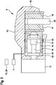
- a wheel brake unit 9 arranged on wheels on the rear axle of the vehicle is shown in detail.
- the wheel brake unit 9 is part of the hydraulic vehicle brake 1 and is supplied with brake fluid 22 from the rear axle brake circuit.
- the wheel brake unit 9 also has an electromechanical braking device, which is part of a parking brake for fixing a vehicle, but can also be used to brake the vehicle when the vehicle is moving, especially at lower vehicle speeds below a speed limit value. Wheel brake units 9 of this type can optionally also be arranged on the wheels of the front axle of the vehicle.
- the electromechanical braking device includes a brake caliper 12 with a caliper 19 which engages over a brake disc 20 .
- the braking device has a motor-gear unit with a DC electric motor as the brake motor 13, the rotor shaft of which drives a spindle 14 in rotation, on which a spindle nut 15 is mounted in a rotationally fixed manner.
- the spindle 14 rotates, the spindle nut 15 is adjusted axially.
- the spindle nut 15 moves within a brake piston 16 which is the carrier of a brake pad 17 which is pressed against the brake disc 20 by the brake piston 16 .
- On the opposite side of the brake disc 20 there is another brake pad 18 which is held in place on the pliers 19 .
- the outside of the brake piston 16 is sealed in a pressure-tight manner with respect to the receiving housing by means of an encompassing sealing ring 23 .
- the spindle nut 15 can move axially forwards in the direction of the brake disc 20 when the spindle 14 rotates, or axially backwards when the spindle 14 rotates in the opposite direction until it reaches an end stop 21.
- the spindle nut 15 acts on the inner end face of the brake piston 16, as a result of which the brake piston 16, which is mounted so as to be axially displaceable in the braking device, is pressed with the brake lining 17 against the facing end face of the brake disc 20.
- the spindle nut 15 represents a transmission element between the brake motor and the brake piston.
- the hydraulic pressure of the brake fluid 22 from the hydraulic vehicle brake 1 acts on the brake piston 16 for the hydraulic braking force.
- the hydraulic pressure can also have a supporting effect when the vehicle is stationary when the electromechanical braking device is actuated, so that the total braking force is made up of the proportion provided by the electric motor and composed of the hydraulic part. While the vehicle is moving, either only the hydraulic vehicle brake is active, or both the hydraulic vehicle brake and the electromechanical braking device, or only the electromechanical braking device, in order to generate braking force.
- the control signals for controlling both the adjustable components of the hydraulic vehicle brake 1 and the electromechanical braking device are generated in the control unit 11, 24, which is the control unit 11 of the brake booster 10 (iBooster) or the ESP control unit 24.
- the parking brake each includes an electromechanical braking device according to 2 on the two rear wheels of the vehicle.
- ESP control unit 24 is assigned to one braking device, for example on the left rear wheel, and control unit 11 of brake booster 10 is assigned to the other braking device.
- the parking brake comprises the two electromechanical braking devices 25a and 25b on the left and right rear wheels of the vehicle, with each electromechanical braking device 25a, 25b having an electric brake motor 13a, 13b.
- the braking device 25a is, for example, the braking device on the left rear wheel and the Braking device 25b around the braking device on the right rear wheel of the vehicle.
- the ESP control device 24 belongs to the braking device 25a, and the iBooster control device 11 to the braking device 25b in order to control the respective brake motors 13a and 13b.
- Each control unit 11, 24 includes a standstill management unit 26a, 26b, a logic unit 27a, 27b and a hardware unit 28a, 28b.
- Standstill management unit 26a, 26b receives signals from other units 29 and 30 in the vehicle, unit 29 being a parking brake switch and unit 30 being a vehicle or vehicle environment sensor system.
- Standstill management unit 26a in ESP control unit 24 receives signals from both parking brake switch 29 and sensors 30.
- Standstill management unit 26b in iBooster control unit 11 only receives signals from sensors 30 and not from parking brake switch 29.
- the logic unit 27a, 27b in the control unit 11, 24 contains the control logic for controlling the respective brake motors 13a, 13b and is implemented in particular as software in the control units.
- the hardware units 28a, 28b include the power electronics for acting on the brake motors 13a, 13b, for example H-bridges.
- the driver can manually generate a trigger signal for activating the parking brake with both electromechanical braking devices 25a and 25b.
- the triggering signal of the parking brake switch 29 is fed to the standstill management unit 26a in the ESP control device 24 as an input signal.
- the triggering signal is transmitted from standstill management unit 26a of ESP control unit 24 to standstill management unit 26b of iBooster control unit 11, so that the triggering signal is available in both control units 11, 24 and accordingly about both Control units 11, 24, the relevant electric brake motors 13a, 13b are controlled.
- the first electromechanical braking device 25a is activated by the ESP control unit 24 when a trigger signal is present, which acts on the electric brake motor 13a via the power electronics 28a.
- the second electric brake motor 13b of the second electromechanical braking device 25b can be controlled by the iBooster control device 11 .
- the triggering signal of the parking brake switch 29 is not available, so that an alternative triggering signal must be generated, which is obtained from the vehicle or vehicle environment sensor system 30 .
- information about the standstill of the vehicle can be obtained from the vehicle's drive motor or from the environment sensors and used as a trigger signal.
- the sensor system 30 also includes a further input system in the vehicle, for example a touch-sensitive screen, via which the driver can trigger the actuation of the parking brake independently of the parking brake switch 29 .
- a further input system in the vehicle for example a touch-sensitive screen, via which the driver can trigger the actuation of the parking brake independently of the parking brake switch 29 .
- brake lights 31a, 31b can be actuated when one or both electromechanical brake devices 25a, 25b are actuated.
- a further communication between the braking devices 25a, 25b takes place via interface units 32a, 32b.
- Each control device also supplies information to a respective diagnostic unit 33a, 33b.
- hydraulic brake booster can be provided via ESP control unit 24 via ESP pump 34 and iBooster control unit 11 can provide electromechanical support via brake booster or iBooster 10 .
- control unit 11, 24, together with an associated brake motor 13, forms a control unit/brake motor unit for generating braking force, in particular for fixing the vehicle at a standstill. If a control unit/brakemotor assembly fails, the remaining, intact control unit/brakemotor assembly can generate braking power. The failure in one of the control unit/brake motor assemblies can involve both the associated control unit and the associated brake motor. It is also possible that the communication between the control units 11, 24 is interrupted, so that no signal can be transmitted from the control unit 24 to the control unit 11.
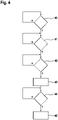
- FIG 4 shows in detail a flowchart with various method steps for generating braking force by actuating the parking brake in the event that a control unit/brake motor unit or the communication between the control units has failed.
- the remaining control unit/brake motor unit is automatically activated if the vehicle speed falls below a limit value or if a parameter in the vehicle indicates that the vehicle is or is about to be stationary.
- a control unit / brake motor unit has failed or the communication between the control units is interrupted.
- the failure of a control unit/brake motor unit can affect both the failure of a control unit and the failure of a brake motor or an interruption in the signal and power transmission. If the query in the first method step 40 reveals that there is actually a failure of a control unit/brake motor unit or an interruption in communication between the control unit, the Yes branch ("Y") is followed to the next method step 41 . Otherwise it is fully functional and the No branch is taken ("N") following returned to the query according to method step 40, which is run through again at cyclic intervals.
- step 41 which is run through in the event of a fault in the parking brake, the query is made as to whether the vehicle speed or a corresponding driving state variable falls below an assigned limit value.
- the limit value is advantageously in the order of a maximum of 10 km/h.
- a parameter can also be considered that indicates an existing or imminent vehicle standstill, for example the ignition status of the drive motor in the vehicle, the status of a door contact switch, in particular on the driver's door, the status of a seat occupancy detection unit for the driver's seat or the State of a buckle for the driver's seat belt. It is also possible to take into account the status of a contact switch on the trunk. If the corresponding parameter indicates a stationary vehicle or an impending vehicle standstill, for example when the driver's door is open or the trunk lid is open, this information can also be used for the method according to the invention for automatically activating the intact control unit/brake motor unit. In a preferred embodiment, the vehicle speed is checked to see whether it falls below the assigned limit value and one or more parameters that indicate an existing or imminent vehicle standstill are taken into account. This increases the safety and plausibility with regard to the automatic generation of braking force.
- step 41 If the query in step 41 shows that the vehicle speed has not fallen below the assigned limit value and/or the parameters under consideration in the vehicle do not indicate an existing or imminent vehicle standstill, the no-branch following the return to the beginning of method step 41 and this step repeated at cyclic intervals. Otherwise, if one condition is met or the various conditions in step 41, the next step 42 is advanced following the yes branch.
- the results of the query in method step 41 are yes, the conditions are in principle present that the intact control unit/brake motor unit can be activated automatically and the braking force can be generated.
- a time increase which is the subject of method step 42, is also taken into account.
- the system waits a defined period of time after detecting that the vehicle is at a standstill before the braking force is automatically generated by the control unit/brake motor unit. By waiting for the period of time in method step 42, a higher level of driving comfort is achieved, in particular during a parking or parking maneuver in the vehicle.
- step 42 If the query in step 42 reveals that a defined period of time has not yet elapsed, following the No branch, a return is made to the beginning of step 42 and this step 42 is run through again at cyclic intervals. If, on the other hand, the query shows that the defined period of time has expired, the Yes branch is followed to the next method step 43, in which the intact control unit/brake motor unit is activated and braking force is generated automatically.
- step 44 conditions are queried that lead to an abortion of braking force generation by the parking brake.
- the automatic generation of braking force by the parking brake is also automatically reduced again when one or more corresponding termination conditions are met, which are checked in method step 44 .
- This is, for example, the drive torque of the drive motor in the vehicle. If the drive torque does not exceed an assigned limit value, the braking force of the parking brake is maintained and, following the No branch, the system returns to the start of the query according to step 44 and runs through the query again at cyclic intervals. If, on the other hand, the query in step 44 shows that the drive torque exceeds the assigned limit value, it must be assumed that vehicle travel is to be resumed, whereupon the yes branch following advanced to step 45 and the braking force of the parking brake is automatically reduced again.
Landscapes
- Engineering & Computer Science (AREA)
- Transportation (AREA)
- Mechanical Engineering (AREA)
- Valves And Accessory Devices For Braking Systems (AREA)
- Regulating Braking Force (AREA)
- Braking Systems And Boosters (AREA)
Description
- Die Erfindung bezieht sich auf ein Verfahren zum Erzeugen von Bremskraft durch Betätigen mindestens eines elektrischen Bremsmotors in einer Fahrzeug-Feststellbremse.
- In der
DE 10 2004 004 992 A1 wird ein Bremssystem für ein Fahrzeug beschrieben, das eine hydraulische Fahrzeugbremse und eine elektromechanische Feststellbremse mit einem elektrischen Bremsmotor umfasst. Der Bremsmotor der Feststellbremse ist in eine Radbremseinheit der hydraulischen Fahrzeugbremse integriert. Der elektrische Bremsmotor verstellt einen Bremskolben in Richtung auf eine Bremsscheibe, um das Fahrzeug im Stillstand festzusetzen. Bei einem regulären Bremsvorgang während der Fahrt wird der Bremskolben bei einer Betätigung der hydraulischen Fahrzeugbremse vom Bremsdruck beaufschlagt. Der elektrische Bremsmotor wird von einem Steuergerät eines ESP-Systems (Elektronisches Stabilitätsprogramm) angesteuert. - In der
DE 10 2007 059 684 A1 wird ein System zum Betreiben einer elektromechanischen Parkbremse für ein Fahrzeug beschrieben, das zwei Steuereinheiten zum Auswerten eines Fahrerparkbremswunsches umfasst. Die beiden Steuereinheiten stehen mit einem Aktuator zum Betätigen der Parkbremse in Verbindung. Beim Auftreten eines Fehlers steuert eine mit Energie versorgte Steuereinheit den Aktuator in der Weise an, dass das Fahrzeug in einer Parkposition festgesetzt wird, sofern ein entsprechender Fahrerparkbremswunsch vorliegt. - In der
EP 1 063 453 B1 wird eine Steuereinrichtung zur Realisierung einer automatischen Park- und Wegrollsperre für ein Kraftfahrzeug beschrieben. Die Steuereinrichtung umfasst ein Steuergerät und einen Aktuator, der von dem Steuergerät angesteuert wird, wenn aufgrund von Sensorsignalen eines Gurtschlosssensors, eines Sitzplatzbelegungssensors und/oder eines Motorhauben- oder Kofferraumklappenöffnungssensors festgestellt wird, dass der Fahrer das Fahrzeug verlassen hat oder zu verlassen wünscht. - Die
DE 10 2007 031 819 A1 offenbart ein Feststellbremssystem für ein Kraftfahrzeug mit einem ersten und einem zweiten Steuergerät zur Ansteuerung eines Bremssteuermotors. Im Normalfall wird der Bremssteuermotor vom ersten Steuergerät angesteuert. Das zweite Steuergerät erzeugt ein Fehlersignal, falls der Bremssteuermotor nicht ordnungsgemäß arbeitet. - Mithilfe des erfindungsgemäßen Verfahrens kann Bremskraft durch Betätigen mindestens eines elektrischen Bremsmotors in einer Fahrzeug-Feststellbremse erzeugt werden. Die Bremskraft dient dazu, das Fahrzeug im Stillstand festzusetzen und gegen ein unbeabsichtigtes Wegrollen zu sichern. Gegebenenfalls kann mithilfe der Fahrzeug-Feststellbremse auch eine Bremskraft während des Fahrens des Fahrzeugs erzeugt werden, so dass die Geschwindigkeit des fahrenden Fahrzeugs verringert wird, insbesondere im niedrigen Geschwindigkeitsbereich, zum Beispiel während eines vom Fahrer oder automatisch durchgeführten Parkvorgangs.
- Die Fahrzeug-Feststellbremse, auf die sich das Fahren bezieht, umfasst zumindest zwei Steuergeräte, über die mindestens ein Bremsmotor der Feststellbremse ansteuerbar ist. Der Bremsmotor ist bevorzugt in einer Radbremseinheit angeordnet und verstellt einen Bremskolben gegen eine Bremsscheibe. Vorteilhafterweise ist die Radbremseinheit Bestandteil einer hydraulischen Fahrzeugbremse im Fahrzeug, wobei bei einer Betätigung der hydraulischen Fahrzeugbremse der Kolben von dem hydraulischen Bremsdruck gegen die Bremsscheibe verstellt wird. In einer alternativen Ausführung ist es möglich, dass die Feststellbremse unabhängig und separat von der hydraulischen Fahrzeugbremse ausgebildet ist.
- In der Fahrzeug-Feststellbremse sind zwei Steuergerät/Bremsmotor-Einheiten mit jeweils einem Steuergerät und einem Bremsmotor gebildet. Im regulären, voll funktionstüchtigen Betrieb der Feststellbremse wird bei einer entsprechenden Anforderung, welche entweder als Fahrerwunsch oder von einem Fahrerassistenzsystem generiert vorliegt, mindestens eine Steuergerät/Bremsmotor-Einheit angesteuert, um eine Bremskraft zu erzeugen. Die Steuergeräte der Feststellbremse kommunizieren miteinander, so dass Informationen von einem Steuergerät zum anderen Steuergerät ausgetauscht werden können.
- Bei dem erfindungsgemäßen Verfahren wird bei einem Ausfall einer ersten Steuergerät/Bremsmotor-Einheit über das zweite Steuergerät selbsttätig die zweite Steuergerät/Bremsmotor-Einheit zur Erzeugung von Bremskraft in Gang gesetzt. Diese Erzeugung von Bremskraft erfolgt ohne Tätigwerden des Fahrers in selbsttätiger und automatisierter Weise, sofern als zusätzliche Bedingung die Fahrzeuggeschwindigkeit unterhalb eines zugeordneten Grenzwerts liegt und/oder eine Kenngröße im Fahrzeug auf einen bereits bestehenden oder zumindest bevorstehenden Fahrzeugstillstand hinweist. Nur für diesen Fall erfolgt die selbsttätige Ansteuerung des mindestens einen Bremsmotors über das zweite, funktionstüchtige Steuergerät, das gemeinsam mit einem ebenfalls funktionstüchtigen Bremsmotor die zweite Steuergerät/Bremsmotor-Einheit bildet. Die zusätzliche Bedingung stellt sicher, dass das Fahrzeug sich bereits im Stillstand befindet oder zumindest sich nur mit einer verhältnismäßig geringen Geschwindigkeit unterhalb des Geschwindigkeitsgrenzwerts bewegt.
- Alternativ zur Geschwindigkeitsbetrachtung kann auch mit der Geschwindigkeit korrespondierende Fahrzustandsgröße des Fahrzeugs herangezogen werden, aus der direkt oder indirekt auch die Fahrzeuggeschwindigkeit geschlossen werden kann. Es kann zum Beispiel über eine Umfeldsensorik ermittelt werden, ob bzw. in welcher Weise sich die Sensorinformationen ändern.
- Die Betrachtung der Fahrzeuggeschwindigkeit oder einer korrespondierenden Fahrzustandsgröße reicht grundsätzlich aus, um den Fahrzeugstillstand oder eine niedrige Geschwindigkeit des Fahrzeugs festzustellen. Zusätzlich oder alternativ kann es aber auch zweckmäßig sein, mindestens eine Kenngröße im Fahrzeug zu analysieren, aus der auf einen bestehenden oder bevorstehenden Fahrzeugstillstand geschlossen werden kann. Hierbei können zum Beispiel der Zündungszustand, der Zustand eines Türkontaktschalters, der Zustand einer Sitzbelegungserkennungseinheit oder der Zustand eines Gurtschlosses berücksichtigt werden. Zum Beispiel deutet der Zündungszustand "aus" auf einen Fahrzeugstillstand hin, ebenso eine geöffnete Fahrzeugtür oder ein geöffneter Kofferraumdeckel, was mit einem entsprechenden Kontaktschalter ermittelbar ist. Aus der Sitzbelegungserkennungseinheit kann festgestellt werden, ob der Fahrersitz belegt ist, so dass im Fall eines manuellen Fahrmodus bei einem nicht belegten Fahrersitz auf einen Fahrzeugstillstand geschlossen werden kann. Auch der aktuelle Zustand des Gurtschlosses am Fahrersitz liefert einen zumindest stützenden Hinweis auf die Belegung des Fahrersitzes, wobei ein offenes Gurtschloss auf einen nicht belegten Fahrersitz oder zumindest auf eine Fahrzeugverlassensabsicht des Fahrers schließen lässt.
- Die auf den bestehenden oder bevorstehenden Fahrzeugstillstand hinweisenden Kenngrößen können gegebenenfalls mit der Fahrzeuggeschwindigkeit oder der mit der Fahrzeuggeschwindigkeit korrespondierenden Fahrzustandsgröße oder untereinander kombiniert werden, wodurch ein höheres Maß an Sicherheit bei der Erkennung eines bereits erfolgten Fahrzeugstillstands oder eines bevorstehenden Fahrzeugstillstands gewonnen wird.
- Es genügt grundsätzlich, genau zwei Steuergeräte und genau einen elektrischen Bremsmotor in der Fahrzeug-Feststellbremse anzuordnen. Die erste Steuergerät/Bremsmotor-Einheit wird in diesem Fall von dem ersten Steuergerät und dem Bremsmotor und die zweite Steuergerät/Bremsmotor-Einheit von dem zweiten Steuergerät und dem Bremsmotor gebildet, so dass der Bremsmotor Bestandteil beider Steuergeräte/Bremsmotor-Einheiten ist. Im Fehlerfall - bei einem Ausfall eines Steuergerätes oder einer Kommunikations- bzw. Energieversorgungsleitung zum Steuergerät - wird auf das andere, intakte Steuergerät umgeschaltet, das gemeinsam mit dem funktionstüchtigen Bremsmotor die zweite Steuergerät/Bremsmotor-Einheit bildet, über die bei Vorliegen der weiteren Bedingungen selbsttätig die Bremskraft erzeugt wird.
- Gemäß einer vorteilhaften Ausführung sind insgesamt genau zwei Steuergeräte und genau zwei Bremsmotoren in der Feststellbremse vorhanden. Das erste Steuergerät und ein erster Bremsmotor bilden die erste Steuergerät/Bremsmotor-Einheit, das zweite Steuergerät und der Bremsmotor die zweite Steuergerät/Bremsmotor-Einheit. Im Normalfall - bei vollständig intakter Funktionstüchtigkeit sämtlicher Komponenten der Feststellbremse - kann sowohl über die erste als auch die zweite Steuergerät/Bremsmotor-Einheit eine Bremskraft zum Festsetzen des Fahrzeugs oder zum Abbremsen des Fahrzeugs erzeugt werden. Die beiden Bremsmotoren sitzen vorzugsweise am linken und rechten Fahrzeugrad an einer gemeinsamen Fahrzeugachse.
- Hierbei ist es vorteilhaft, dass die Steuergeräte miteinander kommunizieren und Informationen von einem Steuergerät an das andere Steuergerät weitergereicht werden. So ist es beispielsweise möglich, dass das erste Steuergerät ein Master-Steuergerät und das zweite Steuergerät ein Slave-Steuergerät bilden, wobei das Master-Steuergerät bei voller Funktionstüchtigkeit der Komponenten der Feststellbremse den Fahrzeugzustand bzw. Fahrzustand auswertet, beispielsweise die Fahrzeuggeschwindigkeit und den Fahrerwunsch zur Betätigung der Feststellbremse, und diese Informationen an das Slave-Steuergerät weiterleitet, woraufhin beide Steuergeräte/Bremsmotor-Einheiten bevorzugt in synchroner Weise betätigt werden. Hierbei kann die Feststellbremse zum Aufbau von Bremskraft geschlossen, zum Abbau von Bremskraft geöffnet werden oder ohne Ansteuerung bleiben.
- Im Fehlerfall, bei dem eine Steuergerät/Bremsmotor-Einheit nicht mehr verfügbar ist oder die Kommunikation zwischen den Steuergeräten gestört ist, wobei die Nichtverfügbarkeit sowohl einen Fehler in einem Steuergerät als auch einen Fehler in einem Bremsmotor betreffen kann, übernimmt die verbleibende, intakte Steuergerät/Bremsmotor-Einheit die selbsttätige Erzeugung von Bremskraft, sofern die Zusatzbedingung im Hinblick auf die Fahrzeuggeschwindigkeit oder den bestehenden bzw. bevorstehenden Fahrzeugstillstand erfüllt ist.
- Beispielsweise wird bei einer gestörten Kommunikation zwischen den Steuergeräten nur die Steuergerät/Bremsmotor-Einheit mit dem Master-Steuergerät zur Erzeugung von Bremskraft angesteuert. Alternativ kann bei einer gestörten Kommunikation zwischen den Steuergeräten nur die Steuergerät/Bremsmotor-Einheit mit dem Slave-Steuergerät zur Erzeugung von Bremskraft angesteuert werden, oder, gemäß noch einer weiteren Alternative, sowohl das Master-Steuergerät als auch das Slave-Steuergerät jeweils zur Erzeugung von Bremskraft unabhängig voneinander angesteuert werden.
- Liegt ein Fehler in einem Steuergerät oder in einem Bremsmotor vor, so wird die jeweils andere Steuergerät/Bremsmotor-Einheit, welche noch intakt ist, zur selbsttätigen Erzeugung von Bremskraft aktiviert. Hierbei steuert das intakte Steuergerät den ihm zugeordneten, intakten Bremsmotor an.
- Sofern die Fahrzeuggeschwindigkeit oder eine hiermit korrespondierende Fahrzustandsgröße für die Entscheidung betrachtet wird, ob bei einem Ausfall einer Steuergerät/Bremsmotor-Einheit selbsttätig über die zweite Steuergerät/Bremsmotor-Einheit Bremskraft erzeugt wird, wird die Information über die Fahrzeuggeschwindigkeit vorzugsweise über eine im Fahrzeug mitgeführte Sensorik ermittelt, beispielsweise die Sensorik eines ESP-Systems (Elektronisches Stabilitätsprogramm).
- Die selbsttätige Bremskrafterzeugung wird erst durchgeführt, nachdem eine definierte Zeitspanne seit dem Erkennen des Fahrzeugstillstands verstrichen ist. Mit dieser zeitverzögerten Betätigung der zweiten, intakten Steuergerät/Bremsmotor-Einheit wird der Vorteil erreicht, dass beispielsweise bei Rangiervorgängen die Feststellbremse erst dann eine Bremskraft erzeugt, wenn der Parkvorgang abgeschlossen ist. Dies gilt sowohl für ein vom Fahrer durchgeführtes Einparken als auch für ein automatisiert geführtes Einparken, bei dem sich der Fahrer gegebenenfalls auch außerhalb des Fahrzeugs befinden kann. Durch die zeitverzögerte Aktivierung der Bremskraft können derartige Einparkvorgänge komfortabel durchgeführt werden.
- Die Zeitspanne, die seit dem Erkennen des Fahrzeugstillstands verstreichen muss, damit selbsttätige Bremskraft erzeugt wird, kann entweder fest vorgegeben werden, beispielsweise zwei Sekunden betragen, oder in Abhängigkeit weiterer Fahrzustandsgrößen oder sonstiger Kenngrößen im Fahrzeug bestimmt werden. Des Weiteren ist es möglich, diese die Zeitverzögerung darstellende Zeitspanne bei einem vom Fahrer durchgeführten Einparkvorgang und einem automatisierten Einparkvorgang unterschiedlich lang zu gestalten, wobei vorteilhafterweise die Zeitverzögerung bei einem vom Fahrer durchgeführten Einparkvorgang länger ist als bei einem automatisiert durchgeführten Einparkvorgang.
- Gemäß noch einer weiteren vorteilhaften Ausführung wird im Anschluss an die selbsttätige Bremskrafterzeugung die Bremskraft auch wieder selbsttätig abgebaut, sofern ein Anfahrwunsch festgestellt wird. Ein derartiger Anfahrwunsch liegt beispielsweise dann vor, falls das Antriebsmoment im Fahrzeug einen zugeordneten Grenzwert übersteigt. Diese Ausführung erhöht die Verfügbarkeit des Fahrzeugs auch für den Fall eines Fehlers in der Fahrzeugfeststellbremse. Die Bremskraft, welche von der Feststellbremse erzeugt wird, wird selbsttätig wieder abgebaut, so dass das Fahrzeug wunschgemäß bewegt werden kann.
- Bei einem der Steuergeräte handelt es sich beispielsweise um dasjenige Steuergerät, das Bestandteil der hydraulischen Fahrzeugbremse ist, beispielsweise um das ESP-Steuergerät (Elektronisches Stabilitätsprogramm), über das Ventile in der hydraulischen Fahrzeugbremse und eine hydraulische Pumpe im Bremssystem angesteuert werden können. Das ESP-Steuergerät übernimmt die zusätzliche Funktion als Steuergerät in einer Steuergerät/Bremsmotor-Einheit. Es handelt sich hierbei insbesondere um das Master-Steuergerät.
- Bei dem zweiten Steuergerät handelt es sich vorteilhafterweise ebenfalls um ein Steuergerät der hydraulischen Fahrzeugbremse, beispielsweise um ein Steuergerät eines elektrisch betätigbaren Bremskraftverstärkers in der hydraulischen Fahrzeugbremse wie zum Beispiel einem iBooster. Dieses zweite Steuergerät ist Bestandteil der zweiten Steuergerät/Bremsmotor-Einheit und übernimmt insbesondere die Funktion des Slave-Steuergeräts.
- Die Erfindung bezieht sich außerdem auf ein Steuergerätesystem bzw. eine Kombination von zumindest zwei Steuergeräten zur Ansteuerung der einstellbaren Komponenten der Feststellbremse, insbesondere der vorzugsweise zwei elektrischen Bremsmotoren.
- Des Weiteren bezieht sich die Erfindung auf eine Fahrzeug-Feststellbremse zum Festsetzen des Fahrzeugs im Stillstand mit zumindest zwei Steuergeräten und mindestens einem Bremsmotor, vorzugsweise zwei Bremsmotoren, der bzw. die über ein Steuergerät ansteuerbar sind. Der mindestens eine elektrische Bremsmotor verstellt zur Erzeugung von Bremskraft einen Bremskolben in Richtung auf eine Bremsscheibe.
- Die Fahrzeug-Feststellbremse kann Bestandteil eines Bremssystems für ein Fahrzeug sein, das außerdem eine hydraulische Fahrzeugbremse umfasst. Vorteilhafterweise wirken der hydraulische Bremsdruck der Fahrzeugbremse und der elektrische Bremsmotor der Feststellbremse auf den gleichen Bremskolben.
- Des Weiteren bezieht sich die Erfindung auf ein Fahrzeug mit einer vorbeschriebenen Fahrzeug-Feststellbremse. In einer weiteren Ausführung bezieht sich die Erfindung auf ein Fahrzeug mit einem Bremssystem, das eine hydraulische Fahrzeugbremse und die vorbeschriebene Fahrzeug-Feststellbremse umfasst.
- Die Erfindung bezieht sich außerdem auf ein Computerprogrammprodukt mit einem Programmcode, der dazu ausgelegt ist, die vorbeschriebenen Verfahrensschritte auszuführen. Das Computerprogrammprodukt läuft in den Steuergeräten ab.
- Weitere Vorteile und zweckmäßige Ausführungen sind den weiteren Ansprüchen, der Figurenbeschreibung und den Zeichnungen zu entnehmen. Es zeigen:
- Fig. 1
- eine schematische Darstellung einer hydraulischen Fahrzeugbremse mit Radbremseinheiten, die zusätzlich mit einem elektrischen Bremsmotor als Teil einer Feststellbremse ausgestattet sind,
- Fig. 2
- einen Schnitt durch eine Feststellbremse mit einem elektrischen Bremsmotor,
- Fig. 3
- eine Prinzipdarstellung der Feststellbremse mit zwei elektrischen Bremsmotoren und jeweils einem Steuergerät,
- Fig. 4
- ein Ablaufschema mit Verfahrensschritten zum Erzeugen von Bremskraft durch Betätigen der Feststellbremse, wenn eine Komponente der Feststellbremse ausgefallen ist.
- In den Figuren sind gleiche Bauteile mit gleichen Bezugszeichen versehen.
- Das in
Fig. 1 dargestellte Bremssystem für ein Fahrzeug umfasst eine hydraulische Fahrzeugbremse 1 mit einem Vorderachs-Bremskreis 2 und einem Hinterachs-Bremskreis 3 zur Versorgung und Ansteuerung von Radbremseinheiten 9 an jedem Rad des Fahrzeugs mit einem unter Hydraulikdruck stehenden Bremsfluid. Die Bremskreise können auch als zwei Diagonalbremskreise mit jeweils einem Vorderrad und einem diagonal dazu angeordneten Hinterrad ausgebildet sein. - Die beiden Bremskreise 2, 3 sind an einen gemeinsamen Hauptbremszylinder 4 angeschlossen, der als Tandemzylinder ausgeführt ist und über einen Bremsflüssigkeitsvorratsbehälter 5 mit Bremsfluid versorgt wird. Der Hauptbremszylinderkolben innerhalb des Hauptbremszylinders 4 wird vom Fahrer über das Bremspedal 6 betätigt, der vom Fahrer ausgeübte Pedalweg wird über einen Pedalwegsensor 7 gemessen. Zwischen dem Bremspedal 6 und dem Hauptbremszylinder 4 befindet sich ein Bremskraftverstärker 10, der beispielsweise einen Elektromotor umfasst, welcher über ein Getriebe den Hauptbremszylinder 4 betätigt (iBooster). Der Bremskraftverstärker 10 stellt eine aktive Bremskomponente zur Beeinflussung des hydraulischen Bremsdrucks dar.
- Die vom Pedalwegsensor 7 gemessene Stellbewegung des Bremspedals 6 wird als Sensorsignal an ein Steuergerät 11 des Bremssystems übermittelt, in welchem Stellsignale zur Ansteuerung des Bremskraftverstärkers 10 erzeugt werden. Die Versorgung der Radbremseinheiten 9 mit Bremsfluid erfolgt in jedem Bremskreis 2, 3 über verschiedene Schaltventile, die gemeinsam mit weiteren Aggregaten Teil einer Bremshydraulik 8 sind. Zur Bremshydraulik 8 gehört des Weiteren eine Hydraulikpumpe, die Bestandteil eines elektronischen Stabilitätsprogramms (ESP) ist, dem ein weiteres Steuergerät zugeordnet ist. Auch die Hydraulikpumpe ist eine aktive Bremskomponente zur Beeinflussung des hydraulischen Bremsdrucks.
- In
Fig. 2 ist eine Radbremseinheit 9, die an Rädern an der Hinterachse des Fahrzeugs angeordnet ist, im Detail dargestellt. Die Radbremseinheit 9 ist Teil der hydraulischen Fahrzeugbremse 1 und wird aus dem Hinterachs-Bremskreis mit Bremsfluid 22 versorgt. Die Radbremseinheit 9 weist außerdem eine elektromechanische Bremsvorrichtung auf, die Teil einer Feststell- bzw. Parkbremse zum Festsetzen eines Fahrzeugs ist, jedoch auch bei einer Bewegung des Fahrzeugs, insbesondere bei kleineren Fahrzeuggeschwindigkeiten unterhalb eines Geschwindigkeits-Grenzwerts zum Abbremsen des Fahrzeugs eingesetzt werden kann. Derartige Radbremseinheiten 9 können gegebenenfalls auch an den Rädern der Vorderachse des Fahrzeugs angeordnet sein. - Die elektromechanische Bremsvorrichtung umfasst einen Bremssattel 12 mit einer Zange 19, welche eine Bremsscheibe 20 übergreift. Als Stellglied weist die Bremsvorrichtung eine Motor-Getriebe-Einheit mit einem Gleichstrom-Elektromotor als Bremsmotor 13 auf, dessen Rotorwelle eine Spindel 14 rotierend antreibt, auf der eine Spindelmutter 15 rotationsfest gelagert ist. Bei einer Rotation der Spindel 14 wird die Spindelmutter 15 axial verstellt. Die Spindelmutter 15 bewegt sich innerhalb eines Bremskolbens 16, der Träger eines Bremsbelags 17 ist, welcher von dem Bremskolben 16 gegen die Bremsscheibe 20 gedrückt wird. Auf der gegenüberliegenden Seite der Bremsscheibe 20 befindet sich ein weiterer Bremsbelag 18, der ortsfest an der Zange 19 gehalten ist. Der Bremskolben 16 ist auf seiner Außenseite über einen umgreifenden Dichtring 23 druckdicht gegenüber dem aufnehmenden Gehäuse abgedichtet.
- Innerhalb des Bremskolbens 16 kann sich die Spindelmutter 15 bei einer Drehbewegung der Spindel 14 axial nach vorne in Richtung auf die Bremsscheibe 20 zu bzw. bei einer entgegen gesetzten Drehbewegung der Spindel 14 axial nach hinten bis zum Erreichen eines Endanschlags 21 bewegen.
- Zum Erzeugen einer Klemmkraft beaufschlagt die Spindelmutter 15 die innere Stirnseite des Bremskolbens 16, wodurch der axial verschieblich in der Bremsvorrichtung gelagerte Bremskolben 16 mit dem Bremsbelag 17 gegen die zugewandte Stirnfläche der Bremsscheibe 20 gedrückt wird. Die Spindelmutter 15 stellt ein Übertragungsglied zwischen dem Bremsmotor und dem Bremskolben dar.
- Für die hydraulische Bremskraft wirkt auf den Bremskolben 16 der hydraulische Druck des Bremsfluids 22 aus der hydraulischen Fahrzeugbremse 1. Der hydraulische Druck kann auch im Fahrzeugstillstand bei Betätigung der elektromechanischen Bremsvorrichtung unterstützend wirksam sein, so dass sich die Gesamt-Bremskraft aus dem elektromotorisch gestellten Anteil und dem hydraulischen Anteil zusammensetzt. Während der Fahrt des Fahrzeugs ist entweder nur die hydraulische Fahrzeugbremse aktiv oder sowohl die hydraulische Fahrzeugbremse als auch die elektromechanische Bremsvorrichtung oder nur die elektromechanische Bremsvorrichtung, um Bremskraft zu erzeugen. Die Stellsignale zur Ansteuerung sowohl der einstellbaren Komponenten der hydraulischen Fahrzeugbremse 1 als auch der elektromechanischen Bremsvorrichtung werden in dem Steuergerät 11, 24 erzeugt, bei dem es sich um das Steuergerät 11 des Bremskraftverstärkers 10 (iBooster) bzw. um das ESP-Steuergerät 24 handelt.
- Die Feststellbremse umfasst jeweils eine elektromechanische Bremsvorrichtung gemäß
Fig. 2 an den beiden Hinterrädern des Fahrzeugs. Einer Bremsvorrichtung, beispielsweise am linken Hinterrad, ist das ESP-Steuergerät 24 zugeordnet, der anderen Bremsvorrichtung das Steuergerät 11 des Bremskraftverstärkers 10. - In
Fig. 3 ist die Feststellbremse schematisch dargestellt. Die Feststellbremse umfasst die beiden elektromechanischen Bremsvorrichtungen 25a und 25b am linken und rechten Hinterrad des Fahrzeugs, wobei zu jeder elektromechanischen Bremsvorrichtung 25a, 25b jeweils ein elektrischer Bremsmotor 13a, 13b gehört. Bei der Bremsvorrichtung 25a handelt es sich beispielsweise um die Bremsvorrichtung am linken Hinterrad und bei der Bremsvorrichtung 25b um die Bremsvorrichtung am rechten Hinterrad des Fahrzeugs. - Zur Bremsvorrichtung 25a gehört das ESP-Steuergerät 24, zur Bremsvorrichtung 25b das iBooster-Steuergerät 11, um die jeweiligen Bremsmotoren 13a bzw. 13b anzusteuern. Jedes Steuergerät 11, 24 umfasst eine Stillstandsmanagementeinheit 26a, 26b, eine Logikeinheit 27a, 27b sowie eine Hardwareeinheit 28a, 28b. Die Stillstandsmanagementeinheit 26a, 26b empfängt Signale von weiteren Einheiten 29 und 30 im Fahrzeug, wobei es sich bei der Einheit 29 um einen Feststellbremsen-Schalter und bei der Einheit 30 um eine Fahrzeug- bzw. Fahrzeug-Umfeldsensorik handelt. Die Stillstandsmanagementeinheit 26a im ESP-Steuergerät 24 empfängt sowohl Signale des Feststellbremsen-Schalters 29 als auch der Sensorik 30. Die Stillstandsmanagementeinheit 26b des iBooster-Steuergerätes 11 empfängt dagegen nur Signale der Sensorik 30, nicht jedoch des Feststellbremsen-Schalters 29.
- Die Logikeinheit 27a, 27b im Steuergerät 11, 24 enthält die Ansteuerungslogik zur Ansteuerung der jeweiligen Bremsmotoren 13a, 13b und ist insbesondere als Software in den Steuergeräten realisiert.
- Die Hardwareeinheiten 28a, 28b umfassen die Leistungselektronik zur Beaufschlagung der Bremsmotoren 13a, 13b, beispielsweise H-Brücken.
- Über eine Betätigung des Feststellbremsen-Schalters 29 kann der Fahrer manuell ein Auslösesignal zur Aktivierung der Feststellbremse mit beiden elektromechanischen Bremsvorrichtungen 25a und 25b erzeugen. Das Auslösesignal des Feststellbremsen-Schalters 29 wird der Stillstandsmanagementeinheit 26a im ESP-Steuergerät 24 als Eingangssignal zugeführt. Das Auslösesignal wird im Normalfall - bei voller Funktionstüchtigkeit beider Steuergeräte 11, 24 - von der Stillstandsmanagementeinheit 26a des ESP-Steuergerätes 24 zu der Stillstandsmanagementeinheit 26b des iBooster-Steuergerätes 11 übertragen, so dass das Auslösesignal in beiden Steuergeräten 11, 24 zur Verfügung steht und entsprechend über beide Steuergeräte 11, 24 die betreffenden elektrischen Bremsmotoren 13a, 13b angesteuert werden.
- Bei einem Ausfall eines Steuergerätes fällt entsprechend auch der jeweilige Bremsmotor aus, es bleibt jedoch die Funktionalität der jeweils anderen elektromechanischen Bremsvorrichtung erhalten, sofern das zweite Steuergerät intakt bleibt.
- Bei einem Ausfall des iBooster-Steuergerätes 11 wird die erste elektromechanische Bremsvorrichtung 25a bei Vorliegen eines Auslösesignals vom ESP-Steuergerät 24 angesteuert, das über die Leistungselektronik 28a den elektrischen Bremsmotor 13a beaufschlagt.
- Bei einem Ausfall des ESP-Steuergerätes 24 kann der zweite elektrische Bremsmotor 13b der zweiten elektromechanischen Bremsvorrichtung 25b von dem iBooster-Steuergerät 11 gesteuert werden. Allerdings steht in diesem Fall das Auslösesignal des Feststellbremsen-Schalters 29 nicht zur Verfügung, so dass ein alternatives Auslösesignal erzeugt werden muss, das aus der Fahrzeug- bzw. Fahrzeugumfeldsensorik 30 gewonnen wird. Beispielsweise können Informationen über den Fahrzeugstillstand vom Antriebsmotor des Fahrzeugs oder aus der Umfeldsensorik gewonnen und als Auslösesignal herangezogen werden.
- Gegebenenfalls umfasst die Sensorik 30 auch ein weiteres Eingabesystem im Fahrzeug, beispielsweise einen berührempfindlichen Bildschirm, über den der Fahrer unabhängig von dem Feststellbremsen-Schalter 29 die Aktuierung der Feststellbremse auslösen kann.
- Über die Steuergeräte 11, 24 sind außerdem noch verschiedene weitere Einheiten ansteuerbar. Beispielsweise können Bremslichter 31a, 31b bei einer Betätigung einer oder beider elektromechanischer Bremsvorrichtungen 25a, 25b betätigt werden. Eine weitere Kommunikation zwischen den Bremsvorrichtungen 25a, 25b findet über Schnittstelleneinheiten 32a, 32b statt. Jedes Steuergerät liefert außerdem Informationen an jeweils eine Diagnoseeinheit 33a, 33b. Bei einem automatisch durchzuführenden Einparkvorgang oder gegebenenfalls auch bei sonstigen Bremsvorgängen kann über das ESP-Steuergerät 24 eine hydraulische Bremskraftunterstützung über die ESP-Pumpe 34 und über das iBooster-Steuergerät 11 eine elektromechanische Unterstützung über den Bremskraftverstärker bzw. iBooster 10 erfolgen.
- Jeweils ein Steuergerät 11, 24 bildet mit einem zugeordneten Bremsmotor 13 eine Steuergerät/Bremsmotor-Einheit zur Erzeugung von Bremskraft, insbesondere zum Festsetzen des Fahrzeugs im Stillstand. Bei einem Ausfall einer Steuergerät/Bremsmotor-Einheit kann die verbleibende, intakte Steuergerät/Bremsmotor-Einheit Bremskraft erzeugen. Der Ausfall in einer der Steuergerät/Bremsmotor-Einheiten kann sowohl das zugehörige Steuergerät als auch den zugehörigen Bremsmotor umfassen. Außerdem ist es möglich, dass die Kommunikation zwischen den Steuergeräten 11, 24 unterbrochen ist, so dass kein Signal vom Steuergerät 24 zum Steuergerät 11 übertragen werden kann.
- In
Fig. 4 ist im Detail ein Ablaufschema mit verschiedenen Verfahrensschritten zum Erzeugen von Bremskraft durch Betätigen der Feststellbremse für den Fall dargestellt, dass eine Steuergerät/Bremsmotor-Einheit oder die Kommunikation zwischen den Steuergeräten ausgefallen ist. Bei dem Verfahren wird die verbleibende Steuergerät/Bremsmotor-Einheit selbsttätig aktiviert, sofern die Fahrzeuggeschwindigkeit einen Grenzwert unterschreitet oder eine Kenngröße im Fahrzeug auf einen bestehenden oder bevorstehenden Fahrzeugstillstand hinweist. - Gemäß
Fig. 4 wird zunächst in einem ersten Verfahrensschritt 40 überprüft, ob eine Steuergerät/Bremsmotor-Einheit ausgefallen ist oder die Kommunikation zwischen den Steuergeräten unterbrochen ist. Der Ausfall einer Steuergerät/Bremsmotor-Einheit kann sowohl den Ausfall eines Steuergerätes als auch den Ausfall eines Bremsmotors bzw. Unterbrechung in der Signal- und Stromübertragung betreffen. Ergibt die Abfrage im ersten Verfahrensschritt 40, dass tatsächlich ein Ausfall einer Steuergerät/Bremsmotor-Einheit oder eine Unterbrechung der Kommunikation zwischen Steuergerät vorliegt, wird der Ja-Verzweigung ("Y") folgend zum nächsten Verfahrensschritt 41 vorgerückt. Andernfalls liegt die volle Funktionstüchtigkeit vor, und es wird der Nein-Verzweigung ("N") folgend wieder zur Abfrage gemäß Verfahrensschritt 40 zurückgekehrt, die in zyklischen Abständen erneut durchlaufen wird. - Im Verfahrensschritt 41, der bei einer Störung in der Feststellbremse durchlaufen wird, erfolgt die Abfrage, ob die Fahrzeuggeschwindigkeit oder eine korrespondierende Fahrzustandsgröße einen zugeordneten Grenzwert unterschreitet. Der Grenzwert liegt vorteilhafterweise in einer Größenordnung von maximal 10 km/h.
- Zusätzlich oder alternativ zum Betrachten der Fahrzustandsgröße kann auch eine Kenngröße betrachtet werden, die auf einen bestehenden oder bevorstehenden Fahrzeugstillstand hinweist, beispielsweise der Zündungszustand des Antriebsmotors im Fahrzeug, der Zustand eines Türkontaktschalters, insbesondere an der Fahrertür, der Zustand einer Sitzbelegungserkennungseinheit für den Fahrersitz oder der Zustand eines Gurtschlosses für den Fahrergurt. Es ist auch möglich, den Zustand eines Kontaktschalters am Kofferraum zu berücksichtigen. Weist die entsprechende Kenngröße auf ein stillstehendes Fahrzeug oder einen bevorstehenden Fahrzeugstillstand hin, beispielsweise bei geöffneter Fahrertür oder geöffnetem Kofferraumdeckel, so kann diese Information ebenfalls für das erfindungsgemäße Verfahren zum selbsttätigen Ansteuern der intakten Steuergerät/Bremsmotor-Einheit verwendet werden. In bevorzugter Ausführung wird sowohl die Fahrzeuggeschwindigkeit auf Unterschreiten des zugeordneten Grenzwerts überprüft als auch eine oder mehrere Kenngrößen berücksichtigt, die auf einen bestehenden oder bevorstehenden Fahrzeugstillstand hinweisen. Dadurch wird die Sicherheit und Plausibilität im Hinblick auf das selbsttätige Erzeugen von Bremskraft erhöht.
- Ergibt die Abfrage im Schritt 41, dass die Fahrzeuggeschwindigkeit nicht unter den zugeordneten Grenzwert gefallen ist und/oder die betrachteten Kenngrößen im Fahrzeug nicht auf einen bestehenden oder bevorstehenden Fahrzeugstillstand hinweisen, wird der Nein-Verzweigung folgend wieder zum Beginn des Verfahrensschrittes 41 zurückgekehrt und dieser Schritt in zyklischen Abständen erneut durchlaufen. Andernfalls, bei Erfüllen der einen Bedingung oder der verschiedenen Bedingungen im Schritt 41, wird der Ja-Verzweigung folgend zum nächsten Schritt 42 vorgerückt.
- Falls der Ja-Ausgang der Abfrage im Verfahrensschritt 41 erreicht ist, liegen prinzipiell die Bedingungen vor, dass die intakte Steuergerät/Bremsmotor-Einheit selbsttätig aktiviert und die Bremskraft erzeugt werden kann. Aus Komfortgründen wird jedoch noch eine Zeitvergrößerung berücksichtigt, die Gegenstand des Verfahrensschrittes 42 ist. Hierbei wird eine definierte Zeitspanne nach dem Erkennen des Fahrzeugstillstands abgewartet, bevor die Bremskraft durch die Ansteuerung der Steuergerät/Bremsmotor-Einheit selbsttätig erzeugt wird. Mit dem Abwarten der Zeitspanne im Verfahrensschritt 42 wird ein höheres Maß an Fahrkomfort insbesondere während eines Einpark- oder Ausparkvorgangs im Fahrzeug erreicht.
- Ergibt die Abfrage im Schritt 42, dass eine definierte Zeitspanne noch nicht verstrichen ist, wird der Nein-Verzweigung folgend wieder zum Beginn des Schrittes 42 zurückgekehrt und dieser Schritt 42 in zyklischen Abständen erneut durchlaufen. Ergibt dagegen die Abfrage, dass die definierte Zeitspanne abgelaufen ist, wird der Ja-Verzweigung folgend zum nächsten Verfahrensschritt 43 vorgerückt, in welchem die intakte Steuergerät/Bremsmotor-Einheit aktiviert und Bremskraft selbsttätig erzeugt wird.
- Im folgenden Verfahrensschritt 44 werden Bedingungen abgefragt, die zu einem Abbruch der Bremskrafterzeugung durch die Feststellbremse führen. Die selbsttätige Bremskrafterzeugung durch die Feststellbremse wird auch selbsttätig wieder abgebaut, wenn eine oder mehrere entsprechende Abbruchbedingungen erfüllt sind, die in Verfahrensschritt 44 abgeprüft werden. Es handelt sich hierbei zum Beispiel um das Antriebsmoment des Antriebsmotors im Fahrzeug. Sofern das Antriebsmoment einen zugeordneten Grenzwert nicht übersteigt, bleibt die Bremskraft der Feststellbremse aufrechterhalten, und es wird der Nein-Verzweigung folgend wieder zum Beginn der Abfrage gemäß Schritt 44 zurückgekehrt und die Abfrage in zyklischen Abständen erneut durchlaufen. Ergibt dagegen die Abfrage im Schritt 44, dass das Antriebsmoment den zugeordneten Grenzwert übersteigt, muss davon ausgegangen werden, dass die Fahrzeugfahrt wieder aufgenommen werden soll, woraufhin der Ja-Verzweigung folgend zum Schritt 45 vorgerückt und die Bremskraft der Feststellbremse selbsttätig wieder abgebaut wird.
Claims (13)
- Verfahren zum Erzeugen von Bremskraft durch Betätigen mindestens eines elektrischen Bremsmotors in einer Fahrzeug-Feststellbremse, die zumindest zwei Steuergeräte (11, 24) zur Ansteuerung mindestens eines Bremsmotors (13) umfasst, wobei bei einem Ausfall einer ersten Steuergerät/Bremsmotor-Einheit selbsttätig eine zweite Steuergerät/Bremsmotor-Einheit zur Erzeugung von Bremskraft aktiviert wird, falls die Fahrzeuggeschwindigkeit oder eine korrespondierende Fahrzustandsgröße einen zugeordneten Grenzwert unterschreitet und/oder eine Kenngröße im Fahrzeug auf einen bestehenden oder bevorstehenden Fahrzeugstillstand hinweist, dadurch gekennzeichnet dass die selbsttätige Bremskrafterzeugung erst durchgeführt wird, nachdem eine definierte Zeitspanne seit dem Erkennen des Fahrzeugstillstands verstrichen ist.
- Verfahren nach Anspruch 1, dadurch gekennzeichnet, dass ein erstes Steuergerät (24) und ein erster Bremsmotor (13) die erste Steuergerät/Bremsmotor-Einheit und ein zweites Steuergerät (11) und ein zweiter Bremsmotor (13) die zweite Steuergerät/Bremsmotor-Einheit bilden.
- Verfahren nach Anspruch 1 oder 2, dadurch gekennzeichnet, dass das erste Steuergerät (24) ein Master-Steuergerät und das zweite Steuergerät (11) ein Slave-Steuergerät bilden, wobei das Master-Steuergerät (24) nach Auswertung des Fahrzeugzustands die Information über die Ansteuerung an das Slave-Steuergerät (11) weiterleitet.
- Verfahren nach einem der Ansprüche 1 bis 3, dadurch gekennzeichnet, dass die auf den bestehenden oder bevorstehenden Fahrzeugstillstand hinweisende Kenngröße der Zündungszustand, der Zustand eines Türkontaktschalters, der Zustand einer Sitzbelegungserkennungseinheit und/oder der Zustand eines Gurtschlosses ist.
- Verfahren nach einem der Ansprüche 1 bis 4, dadurch gekennzeichnet, dass zur Erkennung des bestehenden oder bevorstehenden Fahrzeugstillstands sowohl die Fahrzeuggeschwindigkeit oder eine korrespondierende Fahrzustandsgröße einen Grenzwert unterschreitet und darüber hinaus mindestens eine Kenngröße einen auf den bestehenden oder bevorstehenden Fahrzeugstillstand hinweisenden Wert einnimmt.
- Verfahren nach einem der Ansprüche 1 bis 5, dadurch gekennzeichnet, dass im Anschluss an die die selbsttätige Bremskrafterzeugung die Bremskraft selbsttätig wieder abgebaut wird, wenn ein Anfahrwunsch festgestellt wird.
- Verfahren nach Anspruch 6, dadurch gekennzeichnet, dass ein Anfahrwunsch vorliegt, falls ein Antriebsmoment im Fahrzeug einen zugeordneten Grenzwert übersteigt.
- Kombination von zumindest zwei Steuergeräten, die zur Ansteuerung der einstellbaren Komponenten der Fahrzeug-Feststellbremse zur Durchführung des Verfahrens nach einem der Ansprüche 1 bis 7 ausgelegt ist.
- Fahrzeug-Feststellbremse zum Festsetzen eines Fahrzeugs im Stillstand, mit zumindest zwei Steuergeräten (11, 24) nach Anspruch 8 und mindestens einem Bremsmotor (13), der über mindestens ein Steuergerät (11, 24) ansteuerbar ist, wobei der mindestens eine elektrische Bremsmotor (13) einen Bremskolben (16) in Richtung auf eine Bremsscheibe (20) verstellt.
- Bremssystem für ein Fahrzeug mit einer hydraulischen Fahrzeugbremse (1) und mit einer Fahrzeug-Feststellbremse nach Anspruch 9.
- Fahrzeug mit einem Bremssystem nach Anspruch 10.
- Fahrzeug mit einer Fahrzeug-Feststellbremse nach Anspruch 9.
- Computerprogrammprodukt mit einem Programmcode, der dazu ausgelegt ist, Schritte des Verfahrens nach einem der Ansprüche 1 bis 7 auszuführen, wenn das Computerprogrammprodukt in den Steuergeräten gemäß Anspruch 8 abläuft.
Applications Claiming Priority (3)
| Application Number | Priority Date | Filing Date | Title |
|---|---|---|---|
| DE102017206608 | 2017-04-19 | ||
| DE102018205811.3A DE102018205811A1 (de) | 2017-04-19 | 2018-04-17 | Verfahren zum Erzeugen von Bremskraft durch Betätigen mindestens eines elektrischen Bremsmotors in einer Fahrzeug-Feststellbremse |
| PCT/EP2018/059927 WO2018192986A1 (de) | 2017-04-19 | 2018-04-18 | Verfahren zum erzeugen von bremskraft durch betätigen mindestens eines elektrischen bremsmotors in einer fahrzeug-feststellbremse |
Publications (2)
| Publication Number | Publication Date |
|---|---|
| EP3612419A1 EP3612419A1 (de) | 2020-02-26 |
| EP3612419B1 true EP3612419B1 (de) | 2023-01-25 |
Family
ID=61768256
Family Applications (1)
| Application Number | Title | Priority Date | Filing Date |
|---|---|---|---|
| EP18720764.2A Active EP3612419B1 (de) | 2017-04-19 | 2018-04-18 | Verfahren zum erzeugen von bremskraft durch betätigen mindestens eines elektrischen bremsmotors in einer fahrzeug-feststellbremse |
Country Status (6)
| Country | Link |
|---|---|
| US (1) | US20200023823A1 (de) |
| EP (1) | EP3612419B1 (de) |
| JP (1) | JP6893254B2 (de) |
| CN (1) | CN110505989B (de) |
| DE (2) | DE102018205811A1 (de) |
| WO (2) | WO2018192717A1 (de) |
Families Citing this family (21)
| Publication number | Priority date | Publication date | Assignee | Title |
|---|---|---|---|---|
| KR102030842B1 (ko) * | 2017-09-29 | 2019-10-10 | 주식회사 만도 | 제동 제어 장치 및 그 제어 방법 |
| JP6891852B2 (ja) * | 2018-04-26 | 2021-06-18 | トヨタ自動車株式会社 | 車両の制動制御装置 |
| US12097833B2 (en) * | 2018-09-26 | 2024-09-24 | Hitachi Astemo, Ltd. | Electric brake, and control device |
| CN113646217B (zh) * | 2019-03-29 | 2024-04-26 | 汉拿万都株式会社 | 电子制动系统及其控制方法 |
| KR102847233B1 (ko) * | 2020-03-26 | 2025-08-18 | 에이치엘만도 주식회사 | 전자식 브레이크 시스템 |
| US12115957B2 (en) * | 2019-04-22 | 2024-10-15 | Hitachi Astemo, Ltd. | Control apparatus |
| US12522189B2 (en) * | 2019-06-07 | 2026-01-13 | Hl Mando Corporation | Control device structure of brake system |
| DE102019215189A1 (de) * | 2019-10-02 | 2021-04-08 | Robert Bosch Gmbh | Steuersystem für zumindest zwei motorisierte Bremsvorrichtungen und autonomes Bremsverfahren für ein mit zwei motorisierten Bremsvorrichtungen ausgestattetes Fahrzeug |
| DE102020202920A1 (de) | 2020-03-06 | 2021-09-09 | Continental Teves Ag & Co. Ohg | Bremsanlage mit redundanter Parkbremsfunktion |
| DE102020202919A1 (de) * | 2020-03-06 | 2021-09-09 | Continental Teves Ag & Co. Ohg | Bremsanlage mit redundanter Parkbremsenansteuerung |
| DE102020107548A1 (de) * | 2020-03-19 | 2021-09-23 | Ford Global Technologies Llc | Kraftfahrzeug und Verfahren zum Betreiben eines Kraftfahrzeugs |
| DE102020205848A1 (de) * | 2020-05-08 | 2021-11-11 | Robert Bosch Gesellschaft mit beschränkter Haftung | Verfahren und Vorrichtung zum Betreiben eines Feststellbremssystems |
| US12103509B2 (en) * | 2020-06-12 | 2024-10-01 | Robert Bosch Gmbh | Tracking hydraulic pressure support events in a vehicle |
| DE102020216209A1 (de) | 2020-12-17 | 2022-06-23 | Continental Teves Ag & Co. Ohg | Verfahren zum temporären Halten eines Kraftfahrzeugs, Bremssystem und Bremsmomentensteller |
| US12043228B2 (en) * | 2021-03-01 | 2024-07-23 | ZF Active Safety US Inc. | Apparatus and method for control of a hydraulic brake system |
| KR20220128565A (ko) * | 2021-03-12 | 2022-09-21 | 현대모비스 주식회사 | 통합 전자제동장치 및 그 제어방법 |
| DE102021206459A1 (de) * | 2021-06-23 | 2022-12-29 | Robert Bosch Gesellschaft mit beschränkter Haftung | Verfahren zur Verringerung einer Bremkraftverstärkung im Fehlerfall |
| US11904820B2 (en) | 2021-07-02 | 2024-02-20 | ZF Active Safety US Inc. | Apparatus and method for control of a hydraulic brake by wire system |
| KR20230083025A (ko) * | 2021-12-02 | 2023-06-09 | 현대자동차주식회사 | 브레이크 리던던시 장치의 작동 방법 |
| JP7831341B2 (ja) * | 2023-02-07 | 2026-03-17 | トヨタ自動車株式会社 | 車両制御装置 |
| US12434677B2 (en) | 2023-08-29 | 2025-10-07 | Bendix Commercial Vehicle Systems Llc | Redundant parking brake apparatus for a vehicle and method of operating the same |
Family Cites Families (23)
| Publication number | Priority date | Publication date | Assignee | Title |
|---|---|---|---|---|
| DE19751431A1 (de) * | 1997-11-20 | 1999-07-15 | Itt Mfg Enterprises Inc | Elektromechanische Feststellbremse |
| DE19929360A1 (de) | 1999-06-25 | 2000-12-28 | Volkswagen Ag | Steuereinrichtung zur Realisierung einer automatischen Park- und/oder Wegrollsperre für ein Kraftfahrzeug |
| EP1361124A1 (de) * | 2002-05-03 | 2003-11-12 | Conception et Développement Michelin S.A. | Elektrische Parkbremsvorrichtung |
| JP3945387B2 (ja) * | 2002-11-26 | 2007-07-18 | 株式会社日立製作所 | 電動ブレーキ,その制御装置及び電動ブレーキの制御方法 |
| DE102004004992B4 (de) * | 2004-01-30 | 2008-03-13 | Lucas Automotive Gmbh | Verfahren zum Betreiben der Bremsausrüstung eines Fahrzeugs |
| DE102004059546A1 (de) * | 2004-12-09 | 2006-06-22 | Lucas Automotive Gmbh | Elektronisches System zum Betreiben einer elektromechanischen Feststell-Bremsanlage |
| KR101253179B1 (ko) | 2006-12-14 | 2013-04-12 | 엘지전자 주식회사 | 건조기 |
| DE102007031819A1 (de) * | 2007-07-07 | 2009-01-08 | Daimler Ag | Feststellbremssystem für ein Kraftfahrzeug |
| DE102007059684A1 (de) * | 2007-12-12 | 2009-06-25 | Lucas Automotive Gmbh | Elektronisches System zum Betreiben einer elektromechanischen Parkbremse |
| KR101701125B1 (ko) * | 2009-06-18 | 2017-02-01 | 콘티넨탈 테베스 아게 운트 코. 오하게 | 유압 작동식 서비스 제동 시스템 및 전자기계 작동식 제동 시스템을 구비한 모터 차량 제동 시스템 |
| JP2012035773A (ja) * | 2010-08-09 | 2012-02-23 | Denso Corp | パーキングブレーキ制御装置 |
| DE102011084534A1 (de) * | 2010-10-18 | 2012-04-19 | Continental Teves Ag & Co. Ohg | Fehlersichere Parkbremse für Kraftfahrzeuge |
| DE102012203335A1 (de) * | 2012-03-02 | 2013-09-05 | Robert Bosch Gmbh | Feststellbremse in einem Fahrzeug |
| JP5673639B2 (ja) * | 2012-03-22 | 2015-02-18 | 株式会社アドヴィックス | 電動駐車ブレーキ制御装置 |
| DE102012010562B4 (de) * | 2012-05-26 | 2013-12-24 | Audi Ag | Feststellbremsensystem für ein Fahrzeug |
| DE102013017688B4 (de) * | 2013-10-24 | 2015-03-19 | Audi Ag | Kraftfahrzeug |
| JP6205620B2 (ja) * | 2014-03-31 | 2017-10-04 | 日立オートモティブシステムズ株式会社 | ブレーキ装置 |
| DE102015206572A1 (de) * | 2014-05-15 | 2015-11-19 | Continental Teves Ag & Co. Ohg | Bremsanlage für Kraftfahrzeuge |
| DE102014214375A1 (de) * | 2014-07-23 | 2016-01-28 | Volkswagen Aktiengesellschaft | Bremssystem für ein Fahrzeug, insbesondere einen Kraftwagen, sowie Verfahren zum Betreiben eines solchen Bremssystems |
| DE112015004408T5 (de) * | 2014-09-25 | 2017-06-29 | Honda Motor Co., Ltd. | Vorrichtung zum Steuern eines Fahrzeugs und Steuerverfahren |
| JP6466473B2 (ja) * | 2014-12-27 | 2019-02-06 | マツダ株式会社 | ブレーキ装置 |
| DE102015206034A1 (de) * | 2015-04-02 | 2016-10-06 | Robert Bosch Gmbh | Verfahren und Vorrichtung zum Betreiben eines Bremssystems eines Fahrzeugs, Bremssystem |
| DE102015116317B4 (de) * | 2015-09-28 | 2021-10-21 | Knorr-Bremse Systeme für Nutzfahrzeuge GmbH | Elektro-pneumatische Parkbremseinrichtung eines Fahrzeugs mit weiterem Steuerkreis und Zugfahrzeug mit elektro-pneumatischer Parkbremseinrichtung |
-
2018
- 2018-03-13 WO PCT/EP2018/056240 patent/WO2018192717A1/de not_active Ceased
- 2018-04-17 DE DE102018205811.3A patent/DE102018205811A1/de active Pending
- 2018-04-17 DE DE102018205829.6A patent/DE102018205829A1/de active Pending
- 2018-04-18 JP JP2019556241A patent/JP6893254B2/ja active Active
- 2018-04-18 WO PCT/EP2018/059927 patent/WO2018192986A1/de not_active Ceased
- 2018-04-18 EP EP18720764.2A patent/EP3612419B1/de active Active
- 2018-04-18 CN CN201880026137.0A patent/CN110505989B/zh active Active
- 2018-04-18 US US16/495,215 patent/US20200023823A1/en active Pending
Also Published As
| Publication number | Publication date |
|---|---|
| JP6893254B2 (ja) | 2021-06-23 |
| CN110505989A (zh) | 2019-11-26 |
| WO2018192717A1 (de) | 2018-10-25 |
| US20200023823A1 (en) | 2020-01-23 |
| DE102018205829A1 (de) | 2018-10-25 |
| WO2018192986A1 (de) | 2018-10-25 |
| EP3612419A1 (de) | 2020-02-26 |
| DE102018205811A1 (de) | 2018-10-25 |
| CN110505989B (zh) | 2022-05-24 |
| JP2020516536A (ja) | 2020-06-11 |
Similar Documents
| Publication | Publication Date | Title |
|---|---|---|
| EP3612419B1 (de) | Verfahren zum erzeugen von bremskraft durch betätigen mindestens eines elektrischen bremsmotors in einer fahrzeug-feststellbremse | |
| EP3044056B1 (de) | Fahrassistenzsystem mit gesteigerter ausfallsicherheit und verfügbarkeit | |
| EP3297877B1 (de) | Verfahren zum bereitstellen einer bremskraft in einem fahrzeug | |
| EP3580101B1 (de) | Bremsmotor-steuergerät, bremssystem für ein fahrzeug mit einem elektrischen bremsmotor und verfahren zur ansteuerung des bremsmotorsteuergeräts | |
| DE102015216214A1 (de) | Verfahren und Vorrichtung zur Fahrerassistenz | |
| EP2203334B1 (de) | Anfahrassistenzsystem mit variabler bedingung für das lösen der bremse | |
| EP3515772B1 (de) | Bremssystem-steuergerät für ein fahrzeug | |
| DE102016218209A1 (de) | Bremssystem-Steuergerät für ein Fahrzeug | |
| DE102019200955A1 (de) | Verfahren zur Aktivierung und Deaktivierung eines Steuergeräts | |
| EP3541672B1 (de) | Verfahren zum selbsttätigen abbremsen eines fahrzeugs | |
| DE102016222045A1 (de) | Verfahren und Vorrichtung zum Betreiben einer Bremsanlage eines Kraftfahrzeugs, Bremsanlage | |
| DE102016218214B4 (de) | Bremssystem-Steuergerät für ein Fahrzeug | |
| DE102016214195A1 (de) | Verfahren zur Funktionsprüfung einer elektromechanischen Bremsvorrichtung | |
| EP1807292B1 (de) | Verfahren zum betrieb einer mittels fremdkraft betätigbaren feststellbremse | |
| WO2017211495A1 (de) | Verfahren zum betreiben einer elektromechanischen bremsvorrichtung | |
| EP3436321B1 (de) | Verfahren zum bereitstellen einer bremskraft in einem fahrzeug | |
| DE102016224836A1 (de) | Verfahren zur Überwachung eines Bremssystems mit elektromechanischer Bremsvorrichtung | |
| EP3655297A1 (de) | Vorrichtung und verfahren zum betreiben eines bremssystems eines kraftfahrzeugs | |
| WO2021063577A1 (de) | Verfahren zur steuerung einer elektronisch schlupfregelbaren fremdkraftbremsanlage, insbesondere für ein kraftfahrzeug und elektronisch schlupfregelbaren fremdkraftbremsanlage, insbesondere für ein kraftfahrzeug | |
| DE102019215536A1 (de) | Fahrzeug-Feststellbremse mit einem ersten und einem zweiten elektrischen Bremsmotor | |
| WO2026046682A1 (de) | Verfahren, assistenzsystem und kraftfahrzeug für eine fahrzeugsicherung bei ausgefallener permanenter stillstandssicherung | |
| EP3687870A1 (de) | Verfahren zum einstellen oder zur regelung eines bremsdrucks in einer hydraulischen bremsanlage eines kraftfahrzeugs, vorrichtung und kraftfahrzeug |
Legal Events
| Date | Code | Title | Description |
|---|---|---|---|
| STAA | Information on the status of an ep patent application or granted ep patent |
Free format text: STATUS: UNKNOWN |
|
| STAA | Information on the status of an ep patent application or granted ep patent |
Free format text: STATUS: THE INTERNATIONAL PUBLICATION HAS BEEN MADE |
|
| PUAI | Public reference made under article 153(3) epc to a published international application that has entered the european phase |
Free format text: ORIGINAL CODE: 0009012 |
|
| STAA | Information on the status of an ep patent application or granted ep patent |
Free format text: STATUS: REQUEST FOR EXAMINATION WAS MADE |
|
| 17P | Request for examination filed |
Effective date: 20191119 |
|
| AK | Designated contracting states |
Kind code of ref document: A1 Designated state(s): AL AT BE BG CH CY CZ DE DK EE ES FI FR GB GR HR HU IE IS IT LI LT LU LV MC MK MT NL NO PL PT RO RS SE SI SK SM TR |
|
| AX | Request for extension of the european patent |
Extension state: BA ME |
|
| RAP1 | Party data changed (applicant data changed or rights of an application transferred) |
Owner name: ROBERT BOSCH GMBH |
|
| DAV | Request for validation of the european patent (deleted) | ||
| DAX | Request for extension of the european patent (deleted) | ||
| GRAP | Despatch of communication of intention to grant a patent |
Free format text: ORIGINAL CODE: EPIDOSNIGR1 |
|
| STAA | Information on the status of an ep patent application or granted ep patent |
Free format text: STATUS: GRANT OF PATENT IS INTENDED |
|
| INTG | Intention to grant announced |
Effective date: 20221107 |
|
| GRAS | Grant fee paid |
Free format text: ORIGINAL CODE: EPIDOSNIGR3 |
|
| GRAA | (expected) grant |
Free format text: ORIGINAL CODE: 0009210 |
|
| STAA | Information on the status of an ep patent application or granted ep patent |
Free format text: STATUS: THE PATENT HAS BEEN GRANTED |
|
| AK | Designated contracting states |
Kind code of ref document: B1 Designated state(s): AL AT BE BG CH CY CZ DE DK EE ES FI FR GB GR HR HU IE IS IT LI LT LU LV MC MK MT NL NO PL PT RO RS SE SI SK SM TR |
|
| REG | Reference to a national code |
Ref country code: GB Ref legal event code: FG4D Free format text: NOT ENGLISH |
|
| REG | Reference to a national code |
Ref country code: CH Ref legal event code: EP |
|
| REG | Reference to a national code |
Ref country code: DE Ref legal event code: R096 Ref document number: 502018011507 Country of ref document: DE |
|
| REG | Reference to a national code |
Ref country code: AT Ref legal event code: REF Ref document number: 1545712 Country of ref document: AT Kind code of ref document: T Effective date: 20230215 Ref country code: IE Ref legal event code: FG4D Free format text: LANGUAGE OF EP DOCUMENT: GERMAN |
|
| REG | Reference to a national code |
Ref country code: LT Ref legal event code: MG9D |
|
| REG | Reference to a national code |
Ref country code: NL Ref legal event code: MP Effective date: 20230125 |
|
| PG25 | Lapsed in a contracting state [announced via postgrant information from national office to epo] |
Ref country code: NL Free format text: LAPSE BECAUSE OF FAILURE TO SUBMIT A TRANSLATION OF THE DESCRIPTION OR TO PAY THE FEE WITHIN THE PRESCRIBED TIME-LIMIT Effective date: 20230125 |
|
| PG25 | Lapsed in a contracting state [announced via postgrant information from national office to epo] |
Ref country code: RS Free format text: LAPSE BECAUSE OF FAILURE TO SUBMIT A TRANSLATION OF THE DESCRIPTION OR TO PAY THE FEE WITHIN THE PRESCRIBED TIME-LIMIT Effective date: 20230125 Ref country code: PT Free format text: LAPSE BECAUSE OF FAILURE TO SUBMIT A TRANSLATION OF THE DESCRIPTION OR TO PAY THE FEE WITHIN THE PRESCRIBED TIME-LIMIT Effective date: 20230525 Ref country code: NO Free format text: LAPSE BECAUSE OF FAILURE TO SUBMIT A TRANSLATION OF THE DESCRIPTION OR TO PAY THE FEE WITHIN THE PRESCRIBED TIME-LIMIT Effective date: 20230425 Ref country code: LV Free format text: LAPSE BECAUSE OF FAILURE TO SUBMIT A TRANSLATION OF THE DESCRIPTION OR TO PAY THE FEE WITHIN THE PRESCRIBED TIME-LIMIT Effective date: 20230125 Ref country code: LT Free format text: LAPSE BECAUSE OF FAILURE TO SUBMIT A TRANSLATION OF THE DESCRIPTION OR TO PAY THE FEE WITHIN THE PRESCRIBED TIME-LIMIT Effective date: 20230125 Ref country code: HR Free format text: LAPSE BECAUSE OF FAILURE TO SUBMIT A TRANSLATION OF THE DESCRIPTION OR TO PAY THE FEE WITHIN THE PRESCRIBED TIME-LIMIT Effective date: 20230125 Ref country code: ES Free format text: LAPSE BECAUSE OF FAILURE TO SUBMIT A TRANSLATION OF THE DESCRIPTION OR TO PAY THE FEE WITHIN THE PRESCRIBED TIME-LIMIT Effective date: 20230125 |
|
| PG25 | Lapsed in a contracting state [announced via postgrant information from national office to epo] |
Ref country code: SE Free format text: LAPSE BECAUSE OF FAILURE TO SUBMIT A TRANSLATION OF THE DESCRIPTION OR TO PAY THE FEE WITHIN THE PRESCRIBED TIME-LIMIT Effective date: 20230125 Ref country code: PL Free format text: LAPSE BECAUSE OF FAILURE TO SUBMIT A TRANSLATION OF THE DESCRIPTION OR TO PAY THE FEE WITHIN THE PRESCRIBED TIME-LIMIT Effective date: 20230125 Ref country code: IS Free format text: LAPSE BECAUSE OF FAILURE TO SUBMIT A TRANSLATION OF THE DESCRIPTION OR TO PAY THE FEE WITHIN THE PRESCRIBED TIME-LIMIT Effective date: 20230525 Ref country code: GR Free format text: LAPSE BECAUSE OF FAILURE TO SUBMIT A TRANSLATION OF THE DESCRIPTION OR TO PAY THE FEE WITHIN THE PRESCRIBED TIME-LIMIT Effective date: 20230426 Ref country code: FI Free format text: LAPSE BECAUSE OF FAILURE TO SUBMIT A TRANSLATION OF THE DESCRIPTION OR TO PAY THE FEE WITHIN THE PRESCRIBED TIME-LIMIT Effective date: 20230125 |
|
| REG | Reference to a national code |
Ref country code: DE Ref legal event code: R097 Ref document number: 502018011507 Country of ref document: DE |
|
| PG25 | Lapsed in a contracting state [announced via postgrant information from national office to epo] |
Ref country code: SM Free format text: LAPSE BECAUSE OF FAILURE TO SUBMIT A TRANSLATION OF THE DESCRIPTION OR TO PAY THE FEE WITHIN THE PRESCRIBED TIME-LIMIT Effective date: 20230125 Ref country code: RO Free format text: LAPSE BECAUSE OF FAILURE TO SUBMIT A TRANSLATION OF THE DESCRIPTION OR TO PAY THE FEE WITHIN THE PRESCRIBED TIME-LIMIT Effective date: 20230125 Ref country code: EE Free format text: LAPSE BECAUSE OF FAILURE TO SUBMIT A TRANSLATION OF THE DESCRIPTION OR TO PAY THE FEE WITHIN THE PRESCRIBED TIME-LIMIT Effective date: 20230125 Ref country code: DK Free format text: LAPSE BECAUSE OF FAILURE TO SUBMIT A TRANSLATION OF THE DESCRIPTION OR TO PAY THE FEE WITHIN THE PRESCRIBED TIME-LIMIT Effective date: 20230125 Ref country code: CZ Free format text: LAPSE BECAUSE OF FAILURE TO SUBMIT A TRANSLATION OF THE DESCRIPTION OR TO PAY THE FEE WITHIN THE PRESCRIBED TIME-LIMIT Effective date: 20230125 |
|
| PG25 | Lapsed in a contracting state [announced via postgrant information from national office to epo] |
Ref country code: SK Free format text: LAPSE BECAUSE OF FAILURE TO SUBMIT A TRANSLATION OF THE DESCRIPTION OR TO PAY THE FEE WITHIN THE PRESCRIBED TIME-LIMIT Effective date: 20230125 |
|
| REG | Reference to a national code |
Ref country code: CH Ref legal event code: PL |
|
| PLBE | No opposition filed within time limit |
Free format text: ORIGINAL CODE: 0009261 |
|
| STAA | Information on the status of an ep patent application or granted ep patent |
Free format text: STATUS: NO OPPOSITION FILED WITHIN TIME LIMIT |
|
| PG25 | Lapsed in a contracting state [announced via postgrant information from national office to epo] |
Ref country code: LU Free format text: LAPSE BECAUSE OF NON-PAYMENT OF DUE FEES Effective date: 20230418 |
|
| 26N | No opposition filed |
Effective date: 20231026 |
|
| REG | Reference to a national code |
Ref country code: BE Ref legal event code: MM Effective date: 20230430 |
|
| PG25 | Lapsed in a contracting state [announced via postgrant information from national office to epo] |
Ref country code: MC Free format text: LAPSE BECAUSE OF FAILURE TO SUBMIT A TRANSLATION OF THE DESCRIPTION OR TO PAY THE FEE WITHIN THE PRESCRIBED TIME-LIMIT Effective date: 20230125 |
|
| PG25 | Lapsed in a contracting state [announced via postgrant information from national office to epo] |
Ref country code: SI Free format text: LAPSE BECAUSE OF FAILURE TO SUBMIT A TRANSLATION OF THE DESCRIPTION OR TO PAY THE FEE WITHIN THE PRESCRIBED TIME-LIMIT Effective date: 20230125 Ref country code: MC Free format text: LAPSE BECAUSE OF FAILURE TO SUBMIT A TRANSLATION OF THE DESCRIPTION OR TO PAY THE FEE WITHIN THE PRESCRIBED TIME-LIMIT Effective date: 20230125 Ref country code: LI Free format text: LAPSE BECAUSE OF NON-PAYMENT OF DUE FEES Effective date: 20230430 Ref country code: CH Free format text: LAPSE BECAUSE OF NON-PAYMENT OF DUE FEES Effective date: 20230430 |
|
| REG | Reference to a national code |
Ref country code: IE Ref legal event code: MM4A |
|
| PG25 | Lapsed in a contracting state [announced via postgrant information from national office to epo] |
Ref country code: BE Free format text: LAPSE BECAUSE OF NON-PAYMENT OF DUE FEES Effective date: 20230430 |
|
| PG25 | Lapsed in a contracting state [announced via postgrant information from national office to epo] |
Ref country code: IE Free format text: LAPSE BECAUSE OF NON-PAYMENT OF DUE FEES Effective date: 20230418 |
|
| PG25 | Lapsed in a contracting state [announced via postgrant information from national office to epo] |
Ref country code: IE Free format text: LAPSE BECAUSE OF NON-PAYMENT OF DUE FEES Effective date: 20230418 |
|
| PG25 | Lapsed in a contracting state [announced via postgrant information from national office to epo] |
Ref country code: IT Free format text: LAPSE BECAUSE OF FAILURE TO SUBMIT A TRANSLATION OF THE DESCRIPTION OR TO PAY THE FEE WITHIN THE PRESCRIBED TIME-LIMIT Effective date: 20230125 |
|
| REG | Reference to a national code |
Ref country code: AT Ref legal event code: MM01 Ref document number: 1545712 Country of ref document: AT Kind code of ref document: T Effective date: 20230418 |
|
| PG25 | Lapsed in a contracting state [announced via postgrant information from national office to epo] |
Ref country code: AT Free format text: LAPSE BECAUSE OF NON-PAYMENT OF DUE FEES Effective date: 20230418 |
|
| PG25 | Lapsed in a contracting state [announced via postgrant information from national office to epo] |
Ref country code: AT Free format text: LAPSE BECAUSE OF NON-PAYMENT OF DUE FEES Effective date: 20230418 |
|
| PG25 | Lapsed in a contracting state [announced via postgrant information from national office to epo] |
Ref country code: BG Free format text: LAPSE BECAUSE OF FAILURE TO SUBMIT A TRANSLATION OF THE DESCRIPTION OR TO PAY THE FEE WITHIN THE PRESCRIBED TIME-LIMIT Effective date: 20230125 |
|
| PG25 | Lapsed in a contracting state [announced via postgrant information from national office to epo] |
Ref country code: BG Free format text: LAPSE BECAUSE OF FAILURE TO SUBMIT A TRANSLATION OF THE DESCRIPTION OR TO PAY THE FEE WITHIN THE PRESCRIBED TIME-LIMIT Effective date: 20230125 |
|
| PGFP | Annual fee paid to national office [announced via postgrant information from national office to epo] |
Ref country code: DE Payment date: 20250624 Year of fee payment: 8 |
|
| PGFP | Annual fee paid to national office [announced via postgrant information from national office to epo] |
Ref country code: FR Payment date: 20250422 Year of fee payment: 8 |
|
| PG25 | Lapsed in a contracting state [announced via postgrant information from national office to epo] |
Ref country code: CY Free format text: LAPSE BECAUSE OF FAILURE TO SUBMIT A TRANSLATION OF THE DESCRIPTION OR TO PAY THE FEE WITHIN THE PRESCRIBED TIME-LIMIT; INVALID AB INITIO Effective date: 20180418 |
|
| PG25 | Lapsed in a contracting state [announced via postgrant information from national office to epo] |
Ref country code: HU Free format text: LAPSE BECAUSE OF FAILURE TO SUBMIT A TRANSLATION OF THE DESCRIPTION OR TO PAY THE FEE WITHIN THE PRESCRIBED TIME-LIMIT; INVALID AB INITIO Effective date: 20180418 |
|
| PG25 | Lapsed in a contracting state [announced via postgrant information from national office to epo] |
Ref country code: TR Free format text: LAPSE BECAUSE OF FAILURE TO SUBMIT A TRANSLATION OF THE DESCRIPTION OR TO PAY THE FEE WITHIN THE PRESCRIBED TIME-LIMIT Effective date: 20230125 |
|
| PGFP | Annual fee paid to national office [announced via postgrant information from national office to epo] |
Ref country code: GB Payment date: 20260324 Year of fee payment: 9 |