EP3612419B1 - Procédé servant à générer une force de freinage par l'actionnement d'au moins un moteur de frein électrique dans un frein de stationnement de véhicule - Google Patents
Procédé servant à générer une force de freinage par l'actionnement d'au moins un moteur de frein électrique dans un frein de stationnement de véhicule Download PDFInfo
- Publication number
- EP3612419B1 EP3612419B1 EP18720764.2A EP18720764A EP3612419B1 EP 3612419 B1 EP3612419 B1 EP 3612419B1 EP 18720764 A EP18720764 A EP 18720764A EP 3612419 B1 EP3612419 B1 EP 3612419B1
- Authority
- EP
- European Patent Office
- Prior art keywords
- vehicle
- brake
- control unit
- braking
- unit
- Prior art date
- Legal status (The legal status is an assumption and is not a legal conclusion. Google has not performed a legal analysis and makes no representation as to the accuracy of the status listed.)
- Active
Links
Images


Classifications
-
- B—PERFORMING OPERATIONS; TRANSPORTING
- B60—VEHICLES IN GENERAL
- B60T—VEHICLE BRAKE CONTROL SYSTEMS OR PARTS THEREOF; BRAKE CONTROL SYSTEMS OR PARTS THEREOF, IN GENERAL; ARRANGEMENT OF BRAKING ELEMENTS ON VEHICLES IN GENERAL; PORTABLE DEVICES FOR PREVENTING UNWANTED MOVEMENT OF VEHICLES; VEHICLE MODIFICATIONS TO FACILITATE COOLING OF BRAKES
- B60T8/00—Arrangements for adjusting wheel-braking force to meet varying vehicular or ground-surface conditions, e.g. limiting or varying distribution of braking force
- B60T8/32—Arrangements for adjusting wheel-braking force to meet varying vehicular or ground-surface conditions, e.g. limiting or varying distribution of braking force responsive to a speed condition, e.g. acceleration or deceleration
-
- B—PERFORMING OPERATIONS; TRANSPORTING
- B60—VEHICLES IN GENERAL
- B60T—VEHICLE BRAKE CONTROL SYSTEMS OR PARTS THEREOF; BRAKE CONTROL SYSTEMS OR PARTS THEREOF, IN GENERAL; ARRANGEMENT OF BRAKING ELEMENTS ON VEHICLES IN GENERAL; PORTABLE DEVICES FOR PREVENTING UNWANTED MOVEMENT OF VEHICLES; VEHICLE MODIFICATIONS TO FACILITATE COOLING OF BRAKES
- B60T13/00—Transmitting braking action from initiating means to ultimate brake actuator with power assistance or drive; Brake systems incorporating such transmitting means, e.g. air-pressure brake systems
- B60T13/10—Transmitting braking action from initiating means to ultimate brake actuator with power assistance or drive; Brake systems incorporating such transmitting means, e.g. air-pressure brake systems with fluid assistance, drive, or release
- B60T13/66—Electrical control in fluid-pressure brake systems
- B60T13/662—Electrical control in fluid-pressure brake systems characterised by specified functions of the control system components
-
- B—PERFORMING OPERATIONS; TRANSPORTING
- B60—VEHICLES IN GENERAL
- B60T—VEHICLE BRAKE CONTROL SYSTEMS OR PARTS THEREOF; BRAKE CONTROL SYSTEMS OR PARTS THEREOF, IN GENERAL; ARRANGEMENT OF BRAKING ELEMENTS ON VEHICLES IN GENERAL; PORTABLE DEVICES FOR PREVENTING UNWANTED MOVEMENT OF VEHICLES; VEHICLE MODIFICATIONS TO FACILITATE COOLING OF BRAKES
- B60T13/00—Transmitting braking action from initiating means to ultimate brake actuator with power assistance or drive; Brake systems incorporating such transmitting means, e.g. air-pressure brake systems
- B60T13/74—Transmitting braking action from initiating means to ultimate brake actuator with power assistance or drive; Brake systems incorporating such transmitting means, e.g. air-pressure brake systems with electrical assistance or drive
- B60T13/741—Transmitting braking action from initiating means to ultimate brake actuator with power assistance or drive; Brake systems incorporating such transmitting means, e.g. air-pressure brake systems with electrical assistance or drive acting on an ultimate actuator
-
- B—PERFORMING OPERATIONS; TRANSPORTING
- B60—VEHICLES IN GENERAL
- B60T—VEHICLE BRAKE CONTROL SYSTEMS OR PARTS THEREOF; BRAKE CONTROL SYSTEMS OR PARTS THEREOF, IN GENERAL; ARRANGEMENT OF BRAKING ELEMENTS ON VEHICLES IN GENERAL; PORTABLE DEVICES FOR PREVENTING UNWANTED MOVEMENT OF VEHICLES; VEHICLE MODIFICATIONS TO FACILITATE COOLING OF BRAKES
- B60T7/00—Brake-action initiating means
- B60T7/02—Brake-action initiating means for personal initiation
- B60T7/04—Brake-action initiating means for personal initiation foot actuated
- B60T7/042—Brake-action initiating means for personal initiation foot actuated by electrical means, e.g. using travel or force sensors
-
- B—PERFORMING OPERATIONS; TRANSPORTING
- B60—VEHICLES IN GENERAL
- B60T—VEHICLE BRAKE CONTROL SYSTEMS OR PARTS THEREOF; BRAKE CONTROL SYSTEMS OR PARTS THEREOF, IN GENERAL; ARRANGEMENT OF BRAKING ELEMENTS ON VEHICLES IN GENERAL; PORTABLE DEVICES FOR PREVENTING UNWANTED MOVEMENT OF VEHICLES; VEHICLE MODIFICATIONS TO FACILITATE COOLING OF BRAKES
- B60T7/00—Brake-action initiating means
- B60T7/12—Brake-action initiating means for automatic initiation; for initiation not subject to will of driver or passenger
-
- B—PERFORMING OPERATIONS; TRANSPORTING
- B60—VEHICLES IN GENERAL
- B60T—VEHICLE BRAKE CONTROL SYSTEMS OR PARTS THEREOF; BRAKE CONTROL SYSTEMS OR PARTS THEREOF, IN GENERAL; ARRANGEMENT OF BRAKING ELEMENTS ON VEHICLES IN GENERAL; PORTABLE DEVICES FOR PREVENTING UNWANTED MOVEMENT OF VEHICLES; VEHICLE MODIFICATIONS TO FACILITATE COOLING OF BRAKES
- B60T8/00—Arrangements for adjusting wheel-braking force to meet varying vehicular or ground-surface conditions, e.g. limiting or varying distribution of braking force
- B60T8/17—Using electrical or electronic regulation means to control braking
-
- B—PERFORMING OPERATIONS; TRANSPORTING
- B60—VEHICLES IN GENERAL
- B60T—VEHICLE BRAKE CONTROL SYSTEMS OR PARTS THEREOF; BRAKE CONTROL SYSTEMS OR PARTS THEREOF, IN GENERAL; ARRANGEMENT OF BRAKING ELEMENTS ON VEHICLES IN GENERAL; PORTABLE DEVICES FOR PREVENTING UNWANTED MOVEMENT OF VEHICLES; VEHICLE MODIFICATIONS TO FACILITATE COOLING OF BRAKES
- B60T8/00—Arrangements for adjusting wheel-braking force to meet varying vehicular or ground-surface conditions, e.g. limiting or varying distribution of braking force
- B60T8/32—Arrangements for adjusting wheel-braking force to meet varying vehicular or ground-surface conditions, e.g. limiting or varying distribution of braking force responsive to a speed condition, e.g. acceleration or deceleration
- B60T8/321—Arrangements for adjusting wheel-braking force to meet varying vehicular or ground-surface conditions, e.g. limiting or varying distribution of braking force responsive to a speed condition, e.g. acceleration or deceleration deceleration
-
- B—PERFORMING OPERATIONS; TRANSPORTING
- B60—VEHICLES IN GENERAL
- B60T—VEHICLE BRAKE CONTROL SYSTEMS OR PARTS THEREOF; BRAKE CONTROL SYSTEMS OR PARTS THEREOF, IN GENERAL; ARRANGEMENT OF BRAKING ELEMENTS ON VEHICLES IN GENERAL; PORTABLE DEVICES FOR PREVENTING UNWANTED MOVEMENT OF VEHICLES; VEHICLE MODIFICATIONS TO FACILITATE COOLING OF BRAKES
- B60T13/00—Transmitting braking action from initiating means to ultimate brake actuator with power assistance or drive; Brake systems incorporating such transmitting means, e.g. air-pressure brake systems
- B60T13/74—Transmitting braking action from initiating means to ultimate brake actuator with power assistance or drive; Brake systems incorporating such transmitting means, e.g. air-pressure brake systems with electrical assistance or drive
- B60T13/746—Transmitting braking action from initiating means to ultimate brake actuator with power assistance or drive; Brake systems incorporating such transmitting means, e.g. air-pressure brake systems with electrical assistance or drive and mechanical transmission of the braking action
-
- B—PERFORMING OPERATIONS; TRANSPORTING
- B60—VEHICLES IN GENERAL
- B60T—VEHICLE BRAKE CONTROL SYSTEMS OR PARTS THEREOF; BRAKE CONTROL SYSTEMS OR PARTS THEREOF, IN GENERAL; ARRANGEMENT OF BRAKING ELEMENTS ON VEHICLES IN GENERAL; PORTABLE DEVICES FOR PREVENTING UNWANTED MOVEMENT OF VEHICLES; VEHICLE MODIFICATIONS TO FACILITATE COOLING OF BRAKES
- B60T17/00—Component parts, details, or accessories of power brake systems not covered by groups B60T8/00, B60T13/00 or B60T15/00, or presenting other characteristic features
- B60T17/18—Safety devices; Monitoring
- B60T17/22—Devices for monitoring or checking brake systems; Signal devices
- B60T17/221—Procedure or apparatus for checking or keeping in a correct functioning condition of brake systems
-
- B—PERFORMING OPERATIONS; TRANSPORTING
- B60—VEHICLES IN GENERAL
- B60T—VEHICLE BRAKE CONTROL SYSTEMS OR PARTS THEREOF; BRAKE CONTROL SYSTEMS OR PARTS THEREOF, IN GENERAL; ARRANGEMENT OF BRAKING ELEMENTS ON VEHICLES IN GENERAL; PORTABLE DEVICES FOR PREVENTING UNWANTED MOVEMENT OF VEHICLES; VEHICLE MODIFICATIONS TO FACILITATE COOLING OF BRAKES
- B60T2270/00—Further aspects of brake control systems not otherwise provided for
- B60T2270/40—Failsafe aspects of brake control systems
- B60T2270/402—Back-up
-
- B—PERFORMING OPERATIONS; TRANSPORTING
- B60—VEHICLES IN GENERAL
- B60T—VEHICLE BRAKE CONTROL SYSTEMS OR PARTS THEREOF; BRAKE CONTROL SYSTEMS OR PARTS THEREOF, IN GENERAL; ARRANGEMENT OF BRAKING ELEMENTS ON VEHICLES IN GENERAL; PORTABLE DEVICES FOR PREVENTING UNWANTED MOVEMENT OF VEHICLES; VEHICLE MODIFICATIONS TO FACILITATE COOLING OF BRAKES
- B60T2270/00—Further aspects of brake control systems not otherwise provided for
- B60T2270/40—Failsafe aspects of brake control systems
- B60T2270/413—Plausibility monitoring, cross check, redundancy
-
- B—PERFORMING OPERATIONS; TRANSPORTING
- B60—VEHICLES IN GENERAL
- B60T—VEHICLE BRAKE CONTROL SYSTEMS OR PARTS THEREOF; BRAKE CONTROL SYSTEMS OR PARTS THEREOF, IN GENERAL; ARRANGEMENT OF BRAKING ELEMENTS ON VEHICLES IN GENERAL; PORTABLE DEVICES FOR PREVENTING UNWANTED MOVEMENT OF VEHICLES; VEHICLE MODIFICATIONS TO FACILITATE COOLING OF BRAKES
- B60T2270/00—Further aspects of brake control systems not otherwise provided for
- B60T2270/40—Failsafe aspects of brake control systems
- B60T2270/414—Power supply failure
Definitions
- the invention relates to a method for generating braking force by actuating at least one electric brake motor in a vehicle parking brake.
- a braking system for a vehicle which includes a hydraulic vehicle brake and an electromechanical parking brake with an electric brake motor.
- the brake motor of the parking brake is integrated into a wheel brake unit of the hydraulic vehicle brake.
- the electric brake motor moves a brake piston toward a brake disc to lock the vehicle at a standstill. In a regular braking process while driving, the brake piston is acted upon by the brake pressure when the hydraulic vehicle brake is actuated.
- the electric brake motor is controlled by a control unit of an ESP system (electronic stability program).
- a system for operating an electromechanical parking brake for a vehicle which comprises two control units for evaluating a driver's parking brake request.
- the two control units are connected to an actuator for actuating the parking brake. If an error occurs, a power-supplied control unit controls the actuator in such a way that the Vehicle is fixed in a parking position if there is a corresponding driver parking brake request.
- control device for realizing an automatic parking and roll-away lock for a motor vehicle.
- the control device includes a control unit and an actuator, which is controlled by the control unit when it is determined on the basis of sensor signals from a seat belt buckle sensor, a seat occupancy sensor and/or a bonnet or trunk lid opening sensor that the driver has exited the vehicle or wishes to exit.
- the DE 10 2007 031 819 A1 discloses a parking brake system for a motor vehicle with a first and a second control unit for controlling a brake control motor. Normally, the brake control motor is controlled by the first control unit. The second control unit generates an error signal if the brake control motor is not working properly.
- braking force can be generated by actuating at least one electric brake motor in a vehicle parking brake.
- the braking force serves to fix the vehicle when it is stationary and to secure it against unintentional rolling away.
- the vehicle parking brake can also be used to generate a braking force while the vehicle is being driven, so that the speed of the moving vehicle is reduced, particularly in the low speed range, for example during a parking process carried out by the driver or automatically.
- the vehicle parking brake to which driving relates, comprises at least two control units, via which at least one brake motor of the parking brake can be controlled.
- the brake motor is preferably arranged in a wheel brake unit and adjusts a brake piston against a brake disc.
- the wheel brake unit is part of a hydraulic vehicle brake in the vehicle, with actuation of the hydraulic vehicle brake, the piston is displaced by the hydraulic brake pressure against the brake disc.
- the parking brake it is possible for the parking brake to be designed independently and separately from the hydraulic vehicle brake.
- Two control unit/brake motor units each with a control unit and a brake motor, are formed in the vehicle parking brake.
- at least one control unit/brake motor unit is actuated in order to generate a braking force when there is a corresponding request, which is present either as a driver request or generated by a driver assistance system.
- the parking brake control units communicate with each other so that information can be exchanged from one control unit to another control unit.
- the second control unit/brake motor unit is automatically activated via the second control unit to generate braking force.
- This generation of braking force takes place automatically and automatically without the driver having to take any action if, as an additional condition, the vehicle speed is below an assigned limit value and/or a parameter in the vehicle indicates that the vehicle is already standing still or is at least about to come to a standstill. Only in this case is the automatic activation of the at least one brake motor via the second functional control unit, which together with a likewise functional brake motor forms the second control unit/brake motor unit.
- the additional condition ensures that the vehicle is already stationary or at least is only moving at a relatively low speed below the speed limit.
- the driving state variable of the vehicle corresponding to the speed can also be used, from which the vehicle speed can also be inferred directly or indirectly.
- an environment sensor system can be used to determine whether or how the sensor information changes.
- the vehicle speed or a corresponding driving state variable is sufficient to determine that the vehicle is stationary or that the vehicle speed is low.
- the ignition status, the status of a door contact switch, the status of a seat occupancy detection unit or the status of a seat belt buckle can be taken into account.
- the ignition status "off" indicates that the vehicle is stationary, as does an open vehicle door or an open trunk lid, which can be determined using a corresponding contact switch.
- the seat occupancy detection unit can be used to determine whether the driver's seat is occupied, so that in the case of a manual driving mode when the driver's seat is not occupied, it can be concluded that the vehicle is stationary.
- the current state of the belt buckle on the driver's seat also provides at least a supporting indication of the occupancy of the driver's seat, with an open belt buckle indicating that the driver's seat is not occupied or at least that the driver intends to leave the vehicle.
- the parameters indicating that the vehicle is or is about to come to a standstill can, if necessary, be combined with the vehicle speed or with the driving state variable that corresponds to the vehicle speed, or with one another, as a result of which a higher degree of reliability is gained when the vehicle is already stationary or is about to be stationary.
- the first control unit/brakemotor unit is formed by the first control unit and the brakemotor, and the second control unit/brakemotor unit by the second control unit and the brakemotor, so that the brakemotor is part of both control units/brakemotor units.
- intact Control unit switched which together with the functional brake motor forms the second control unit/brake motor unit, via which the braking force is automatically generated when the other conditions are met.
- the parking brake there are exactly two control units and exactly two brake motors in the parking brake.
- the first control unit and a first brake motor form the first control unit/brake motor unit
- the second control unit and the brake motor form the second control unit/brake motor unit.
- the two brake motors are preferably located on the left and right vehicle wheels on a common vehicle axle.
- control units it is advantageous here for the control units to communicate with one another and for information to be passed on from one control unit to the other control unit.
- the first control unit to form a master control unit and the second control unit to form a slave control unit, with the master control unit evaluating the vehicle status or driving status, for example the vehicle speed and the driver's request, when the parking brake components are fully functional Actuation of the parking brake, and forwards this information to the slave controller, whereupon both controllers / brake motor units are preferably operated in a synchronous manner.
- the parking brake can be closed to build up braking force, opened to reduce braking force or remain unactivated.
- both the master control unit and the slave control unit can each be used to generate it be controlled independently of each other by braking force.
- control unit/brake motor unit If there is a fault in a control unit or in a brake motor, the other control unit/brake motor unit, which is still intact, is activated to automatically generate braking force.
- the intact control unit controls the intact brake motor assigned to it.
- the information about the vehicle speed is preferably transmitted via a sensor system carried in the vehicle determined, for example the sensors of an ESP system (electronic stability program).
- the automatic generation of braking force is only carried out after a defined period of time has elapsed since the standstill of the vehicle was detected.
- the advantage is achieved that, for example when maneuvering, the parking brake only generates a braking force when the parking process is complete. This applies both to parking performed by the driver and to automated parking, in which the driver may also be outside of the vehicle. Due to the time-delayed activation of the braking force, such parking maneuvers can be carried out comfortably.
- the period of time that must elapse since the vehicle was detected as stationary so that automatic braking force is generated can either be fixed be specified, for example two seconds, or be determined depending on other driving condition variables or other parameters in the vehicle. Furthermore, it is possible to To make time delay representative period of time in a parking process performed by the driver and an automated parking process of different lengths, wherein advantageously the time delay in a parking process performed by the driver is longer than in an automated parking process performed.
- the braking force is also automatically reduced again if a desire to start off is determined.
- a desire to start off is present, for example, if the drive torque in the vehicle exceeds an assigned limit value.
- This design also increases the availability of the vehicle in the event of a fault in the vehicle's parking brake. The braking force generated by the parking brake is automatically reduced again so that the vehicle can be moved as desired.
- One of the control units is, for example, the control unit that is part of the hydraulic vehicle brake, for example the ESP (electronic stability program) control unit, which can be used to control the valves in the hydraulic vehicle brake and a hydraulic pump in the brake system.
- the ESP control unit assumes the additional function of a control unit in a control unit/brake motor unit. This is in particular the master control unit.
- the second control device is advantageously also a control device for the hydraulic vehicle brake, for example a control device for an electrically actuable brake booster in the hydraulic vehicle brake, such as an iBooster.
- This second control unit is part of the second control unit/brake motor unit and, in particular, takes on the function of the slave control unit.
- the invention also relates to a control unit system or a combination of at least two control units for controlling the adjustable components of the parking brake, in particular the preferably two electric brake motors.
- the invention relates to a vehicle parking brake for fixing the vehicle at a standstill with at least two control units and at least one brake motor, preferably two brake motors, which can be controlled via a control unit.
- the at least one electric brake motor adjusts a brake piston in the direction of a brake disk in order to generate braking force.
- the vehicle parking brake may be part of a braking system for a vehicle that also includes a hydraulic vehicle brake.
- the hydraulic brake pressure of the vehicle brake and the electric brake motor of the parking brake act on the same brake piston.
- the invention relates to a vehicle with a vehicle parking brake as described above.
- the invention relates to a vehicle with a braking system that includes a hydraulic vehicle brake and the vehicle parking brake described above.
- the invention also relates to a computer program product with a program code that is designed to carry out the method steps described above.
- the computer program product runs in the control units.
- the braking system shown for a vehicle comprises a hydraulic vehicle brake 1 with a front-axle brake circuit 2 and a rear-axle brake circuit 3 for supplying and controlling wheel brake units 9 on each wheel of the vehicle with brake fluid under hydraulic pressure.
- the brake circuits can also be designed as two diagonal brake circuits, each with a front wheel and a rear wheel arranged diagonally thereto.
- the two brake circuits 2, 3 are connected to a common master brake cylinder 4, which is designed as a tandem cylinder and is supplied with brake fluid via a brake fluid reservoir 5.
- the master brake cylinder piston inside the master brake cylinder 4 is actuated by the driver via the brake pedal 6 , the pedal travel exerted by the driver is measured via a pedal travel sensor 7 .
- a brake booster 10 which comprises, for example, an electric motor which actuates the master brake cylinder 4 via a transmission (iBooster).
- the brake booster 10 represents an active brake component for influencing the hydraulic brake pressure.
- the actuating movement of the brake pedal 6 measured by the pedal travel sensor 7 is transmitted as a sensor signal to a control unit 11 of the brake system, in which actuating signals for actuating the brake booster 10 are generated.
- the wheel brake units 9 are supplied with brake fluid in each brake circuit 2, 3 via various switching valves which, together with other units, are part of a brake hydraulic system 8.
- the brake hydraulics 8 includes the Furthermore, a hydraulic pump, which is part of an electronic stability program (ESP), to which another control unit is assigned.
- the hydraulic pump is also an active braking component for influencing the hydraulic braking pressure.
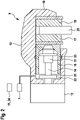
- a wheel brake unit 9 arranged on wheels on the rear axle of the vehicle is shown in detail.
- the wheel brake unit 9 is part of the hydraulic vehicle brake 1 and is supplied with brake fluid 22 from the rear axle brake circuit.
- the wheel brake unit 9 also has an electromechanical braking device, which is part of a parking brake for fixing a vehicle, but can also be used to brake the vehicle when the vehicle is moving, especially at lower vehicle speeds below a speed limit value. Wheel brake units 9 of this type can optionally also be arranged on the wheels of the front axle of the vehicle.
- the electromechanical braking device includes a brake caliper 12 with a caliper 19 which engages over a brake disc 20 .
- the braking device has a motor-gear unit with a DC electric motor as the brake motor 13, the rotor shaft of which drives a spindle 14 in rotation, on which a spindle nut 15 is mounted in a rotationally fixed manner.
- the spindle 14 rotates, the spindle nut 15 is adjusted axially.
- the spindle nut 15 moves within a brake piston 16 which is the carrier of a brake pad 17 which is pressed against the brake disc 20 by the brake piston 16 .
- On the opposite side of the brake disc 20 there is another brake pad 18 which is held in place on the pliers 19 .
- the outside of the brake piston 16 is sealed in a pressure-tight manner with respect to the receiving housing by means of an encompassing sealing ring 23 .
- the spindle nut 15 can move axially forwards in the direction of the brake disc 20 when the spindle 14 rotates, or axially backwards when the spindle 14 rotates in the opposite direction until it reaches an end stop 21.
- the spindle nut 15 acts on the inner end face of the brake piston 16, as a result of which the brake piston 16, which is mounted so as to be axially displaceable in the braking device, is pressed with the brake lining 17 against the facing end face of the brake disc 20.
- the spindle nut 15 represents a transmission element between the brake motor and the brake piston.
- the hydraulic pressure of the brake fluid 22 from the hydraulic vehicle brake 1 acts on the brake piston 16 for the hydraulic braking force.
- the hydraulic pressure can also have a supporting effect when the vehicle is stationary when the electromechanical braking device is actuated, so that the total braking force is made up of the proportion provided by the electric motor and composed of the hydraulic part. While the vehicle is moving, either only the hydraulic vehicle brake is active, or both the hydraulic vehicle brake and the electromechanical braking device, or only the electromechanical braking device, in order to generate braking force.
- the control signals for controlling both the adjustable components of the hydraulic vehicle brake 1 and the electromechanical braking device are generated in the control unit 11, 24, which is the control unit 11 of the brake booster 10 (iBooster) or the ESP control unit 24.
- the parking brake each includes an electromechanical braking device according to 2 on the two rear wheels of the vehicle.
- ESP control unit 24 is assigned to one braking device, for example on the left rear wheel, and control unit 11 of brake booster 10 is assigned to the other braking device.
- the parking brake comprises the two electromechanical braking devices 25a and 25b on the left and right rear wheels of the vehicle, with each electromechanical braking device 25a, 25b having an electric brake motor 13a, 13b.
- the braking device 25a is, for example, the braking device on the left rear wheel and the Braking device 25b around the braking device on the right rear wheel of the vehicle.
- the ESP control device 24 belongs to the braking device 25a, and the iBooster control device 11 to the braking device 25b in order to control the respective brake motors 13a and 13b.
- Each control unit 11, 24 includes a standstill management unit 26a, 26b, a logic unit 27a, 27b and a hardware unit 28a, 28b.
- Standstill management unit 26a, 26b receives signals from other units 29 and 30 in the vehicle, unit 29 being a parking brake switch and unit 30 being a vehicle or vehicle environment sensor system.
- Standstill management unit 26a in ESP control unit 24 receives signals from both parking brake switch 29 and sensors 30.
- Standstill management unit 26b in iBooster control unit 11 only receives signals from sensors 30 and not from parking brake switch 29.
- the logic unit 27a, 27b in the control unit 11, 24 contains the control logic for controlling the respective brake motors 13a, 13b and is implemented in particular as software in the control units.
- the hardware units 28a, 28b include the power electronics for acting on the brake motors 13a, 13b, for example H-bridges.
- the driver can manually generate a trigger signal for activating the parking brake with both electromechanical braking devices 25a and 25b.
- the triggering signal of the parking brake switch 29 is fed to the standstill management unit 26a in the ESP control device 24 as an input signal.
- the triggering signal is transmitted from standstill management unit 26a of ESP control unit 24 to standstill management unit 26b of iBooster control unit 11, so that the triggering signal is available in both control units 11, 24 and accordingly about both Control units 11, 24, the relevant electric brake motors 13a, 13b are controlled.
- the first electromechanical braking device 25a is activated by the ESP control unit 24 when a trigger signal is present, which acts on the electric brake motor 13a via the power electronics 28a.
- the second electric brake motor 13b of the second electromechanical braking device 25b can be controlled by the iBooster control device 11 .
- the triggering signal of the parking brake switch 29 is not available, so that an alternative triggering signal must be generated, which is obtained from the vehicle or vehicle environment sensor system 30 .
- information about the standstill of the vehicle can be obtained from the vehicle's drive motor or from the environment sensors and used as a trigger signal.
- the sensor system 30 also includes a further input system in the vehicle, for example a touch-sensitive screen, via which the driver can trigger the actuation of the parking brake independently of the parking brake switch 29 .
- a further input system in the vehicle for example a touch-sensitive screen, via which the driver can trigger the actuation of the parking brake independently of the parking brake switch 29 .
- brake lights 31a, 31b can be actuated when one or both electromechanical brake devices 25a, 25b are actuated.
- a further communication between the braking devices 25a, 25b takes place via interface units 32a, 32b.
- Each control device also supplies information to a respective diagnostic unit 33a, 33b.
- hydraulic brake booster can be provided via ESP control unit 24 via ESP pump 34 and iBooster control unit 11 can provide electromechanical support via brake booster or iBooster 10 .
- control unit 11, 24, together with an associated brake motor 13, forms a control unit/brake motor unit for generating braking force, in particular for fixing the vehicle at a standstill. If a control unit/brakemotor assembly fails, the remaining, intact control unit/brakemotor assembly can generate braking power. The failure in one of the control unit/brake motor assemblies can involve both the associated control unit and the associated brake motor. It is also possible that the communication between the control units 11, 24 is interrupted, so that no signal can be transmitted from the control unit 24 to the control unit 11.
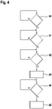
- FIG 4 shows in detail a flowchart with various method steps for generating braking force by actuating the parking brake in the event that a control unit/brake motor unit or the communication between the control units has failed.
- the remaining control unit/brake motor unit is automatically activated if the vehicle speed falls below a limit value or if a parameter in the vehicle indicates that the vehicle is or is about to be stationary.
- a control unit / brake motor unit has failed or the communication between the control units is interrupted.
- the failure of a control unit/brake motor unit can affect both the failure of a control unit and the failure of a brake motor or an interruption in the signal and power transmission. If the query in the first method step 40 reveals that there is actually a failure of a control unit/brake motor unit or an interruption in communication between the control unit, the Yes branch ("Y") is followed to the next method step 41 . Otherwise it is fully functional and the No branch is taken ("N") following returned to the query according to method step 40, which is run through again at cyclic intervals.
- step 41 which is run through in the event of a fault in the parking brake, the query is made as to whether the vehicle speed or a corresponding driving state variable falls below an assigned limit value.
- the limit value is advantageously in the order of a maximum of 10 km/h.
- a parameter can also be considered that indicates an existing or imminent vehicle standstill, for example the ignition status of the drive motor in the vehicle, the status of a door contact switch, in particular on the driver's door, the status of a seat occupancy detection unit for the driver's seat or the State of a buckle for the driver's seat belt. It is also possible to take into account the status of a contact switch on the trunk. If the corresponding parameter indicates a stationary vehicle or an impending vehicle standstill, for example when the driver's door is open or the trunk lid is open, this information can also be used for the method according to the invention for automatically activating the intact control unit/brake motor unit. In a preferred embodiment, the vehicle speed is checked to see whether it falls below the assigned limit value and one or more parameters that indicate an existing or imminent vehicle standstill are taken into account. This increases the safety and plausibility with regard to the automatic generation of braking force.
- step 41 If the query in step 41 shows that the vehicle speed has not fallen below the assigned limit value and/or the parameters under consideration in the vehicle do not indicate an existing or imminent vehicle standstill, the no-branch following the return to the beginning of method step 41 and this step repeated at cyclic intervals. Otherwise, if one condition is met or the various conditions in step 41, the next step 42 is advanced following the yes branch.
- the results of the query in method step 41 are yes, the conditions are in principle present that the intact control unit/brake motor unit can be activated automatically and the braking force can be generated.
- a time increase which is the subject of method step 42, is also taken into account.
- the system waits a defined period of time after detecting that the vehicle is at a standstill before the braking force is automatically generated by the control unit/brake motor unit. By waiting for the period of time in method step 42, a higher level of driving comfort is achieved, in particular during a parking or parking maneuver in the vehicle.
- step 42 If the query in step 42 reveals that a defined period of time has not yet elapsed, following the No branch, a return is made to the beginning of step 42 and this step 42 is run through again at cyclic intervals. If, on the other hand, the query shows that the defined period of time has expired, the Yes branch is followed to the next method step 43, in which the intact control unit/brake motor unit is activated and braking force is generated automatically.
- step 44 conditions are queried that lead to an abortion of braking force generation by the parking brake.
- the automatic generation of braking force by the parking brake is also automatically reduced again when one or more corresponding termination conditions are met, which are checked in method step 44 .
- This is, for example, the drive torque of the drive motor in the vehicle. If the drive torque does not exceed an assigned limit value, the braking force of the parking brake is maintained and, following the No branch, the system returns to the start of the query according to step 44 and runs through the query again at cyclic intervals. If, on the other hand, the query in step 44 shows that the drive torque exceeds the assigned limit value, it must be assumed that vehicle travel is to be resumed, whereupon the yes branch following advanced to step 45 and the braking force of the parking brake is automatically reduced again.
Landscapes
- Engineering & Computer Science (AREA)
- Transportation (AREA)
- Mechanical Engineering (AREA)
- Valves And Accessory Devices For Braking Systems (AREA)
- Regulating Braking Force (AREA)
- Braking Systems And Boosters (AREA)
Claims (13)
- Procédé permettant de générer une force de freinage par l'actionnement d'au moins un moteur de frein électrique dans un frein de stationnement de véhicule qui comprend au moins deux appareils de commande (11, 24) pour piloter au moins un moteur de frein (13), dans lequel, en cas de défaillance d'un premier ensemble appareil de commande/moteur de frein, un deuxième ensemble appareil de commande/moteur de frein est activé de manière autonome pour générer une force de freinage si la vitesse du véhicule ou une grandeur d'état de conduite correspondante est inférieure à une valeur limite associée, et/ou une grandeur caractéristique dans le véhicule indique un arrêt du véhicule avéré ou imminent,
caractérisé en ce que la génération autonome d'une force de freinage n'est effectuée qu'après expiration d'un délai défini depuis l'identification de l'arrêt du véhicule. - Procédé selon la revendication 1, caractérisé en ce qu'un premier appareil de commande (24) et un premier moteur de frein (13) constituent le premier ensemble appareil de commande/moteur de frein, et un deuxième appareil de commande (11) et un deuxième moteur de frein (13) constituent le deuxième ensemble appareil de commande/moteur de frein.
- Procédé selon la revendication 1 ou 2, caractérisé en ce que le premier appareil de commande (24) est un appareil de commande maître et le deuxième appareil de commande (11) est un appareil de commande esclave,
dans lequel l'appareil de commande maître (24) retransmet l'information concernant le pilotage à l'appareil de commande esclave (11) après une évaluation de l'état du véhicule. - Procédé selon l'une quelconque des revendications 1 à 3, caractérisé en ce que la grandeur caractéristique indiquant l'arrêt du véhicule avéré ou imminent est l'état d'allumage, l'état d'un contacteur de portière, l'état d'une unité d'identification d'occupation des sièges et/ou l'état d'une boucle de ceinture.
- Procédé selon l'une quelconque des revendications 1 à 4, caractérisé en ce que pour identifier l'arrêt du véhicule avéré ou imminent, à la fois la vitesse du véhicule ou une grandeur d'état du véhicule correspondante est inférieure à une valeur limite, et en plus au moins une grandeur caractéristique adopte une valeur indiquant l'arrêt du véhicule avéré ou imminent.
- Procédé selon l'une quelconque des revendications 1 à 5, caractérisé en ce que suite à la génération autonome d'une force de freinage, la force de freinage est à nouveau réduite de manière autonome si un souhait de démarrage est constaté.
- Procédé selon la revendication 6, caractérisé en ce qu'un souhait de démarrage est présent si un couple d'entraînement dans le véhicule dépasse une valeur limite associée.
- Combinaison d'au moins deux appareils de commande, qui est conçue pour piloter les composants réglables du frein de stationnement de véhicule pour exécuter le procédé selon l'une quelconque des revendications 1 à 7 .
- Frein de stationnement de véhicule pour immobiliser un véhicule à l'arrêt, comprenant au moins deux appareils de commande (11, 24) selon la revendication 8 et au moins un moteur de frein (13) qui peut être piloté par l'intermédiaire d'au moins un appareil de commande (11, 24), dans lequel ledit au moins un moteur de frein électrique (13) ajuste un piston de frein (16) en direction d'un disque de frein (20) .
- Système de freinage pour un véhicule comprenant un frein de véhicule hydraulique (1) et un frein de stationnement de véhicule selon la revendication 9.
- Véhicule comprenant un système de freinage selon la revendication 10.
- Véhicule comprenant un frein de stationnement de véhicule selon la revendication 9.
- Produit de programme informatique comprenant du code programme qui est conçu pour exécuter les étapes du procédé selon l'une quelconque des revendications 1 à 7 si le produit de programme informatique est exécuté sur les appareils de commande selon la revendication 8.
Applications Claiming Priority (3)
| Application Number | Priority Date | Filing Date | Title |
|---|---|---|---|
| DE102017206608 | 2017-04-19 | ||
| DE102018205811.3A DE102018205811A1 (de) | 2017-04-19 | 2018-04-17 | Verfahren zum Erzeugen von Bremskraft durch Betätigen mindestens eines elektrischen Bremsmotors in einer Fahrzeug-Feststellbremse |
| PCT/EP2018/059927 WO2018192986A1 (fr) | 2017-04-19 | 2018-04-18 | Procédé servant à générer une force de freinage par l'actionnement d'au moins un moteur de frein électrique dans un frein de stationnement de véhicule |
Publications (2)
| Publication Number | Publication Date |
|---|---|
| EP3612419A1 EP3612419A1 (fr) | 2020-02-26 |
| EP3612419B1 true EP3612419B1 (fr) | 2023-01-25 |
Family
ID=61768256
Family Applications (1)
| Application Number | Title | Priority Date | Filing Date |
|---|---|---|---|
| EP18720764.2A Active EP3612419B1 (fr) | 2017-04-19 | 2018-04-18 | Procédé servant à générer une force de freinage par l'actionnement d'au moins un moteur de frein électrique dans un frein de stationnement de véhicule |
Country Status (6)
| Country | Link |
|---|---|
| US (1) | US20200023823A1 (fr) |
| EP (1) | EP3612419B1 (fr) |
| JP (1) | JP6893254B2 (fr) |
| CN (1) | CN110505989B (fr) |
| DE (2) | DE102018205811A1 (fr) |
| WO (2) | WO2018192717A1 (fr) |
Families Citing this family (21)
| Publication number | Priority date | Publication date | Assignee | Title |
|---|---|---|---|---|
| KR102030842B1 (ko) * | 2017-09-29 | 2019-10-10 | 주식회사 만도 | 제동 제어 장치 및 그 제어 방법 |
| JP6891852B2 (ja) * | 2018-04-26 | 2021-06-18 | トヨタ自動車株式会社 | 車両の制動制御装置 |
| US12097833B2 (en) * | 2018-09-26 | 2024-09-24 | Hitachi Astemo, Ltd. | Electric brake, and control device |
| CN113646217B (zh) * | 2019-03-29 | 2024-04-26 | 汉拿万都株式会社 | 电子制动系统及其控制方法 |
| KR102847233B1 (ko) * | 2020-03-26 | 2025-08-18 | 에이치엘만도 주식회사 | 전자식 브레이크 시스템 |
| US12115957B2 (en) * | 2019-04-22 | 2024-10-15 | Hitachi Astemo, Ltd. | Control apparatus |
| US12522189B2 (en) * | 2019-06-07 | 2026-01-13 | Hl Mando Corporation | Control device structure of brake system |
| DE102019215189A1 (de) * | 2019-10-02 | 2021-04-08 | Robert Bosch Gmbh | Steuersystem für zumindest zwei motorisierte Bremsvorrichtungen und autonomes Bremsverfahren für ein mit zwei motorisierten Bremsvorrichtungen ausgestattetes Fahrzeug |
| DE102020202920A1 (de) | 2020-03-06 | 2021-09-09 | Continental Teves Ag & Co. Ohg | Bremsanlage mit redundanter Parkbremsfunktion |
| DE102020202919A1 (de) * | 2020-03-06 | 2021-09-09 | Continental Teves Ag & Co. Ohg | Bremsanlage mit redundanter Parkbremsenansteuerung |
| DE102020107548A1 (de) * | 2020-03-19 | 2021-09-23 | Ford Global Technologies Llc | Kraftfahrzeug und Verfahren zum Betreiben eines Kraftfahrzeugs |
| DE102020205848A1 (de) * | 2020-05-08 | 2021-11-11 | Robert Bosch Gesellschaft mit beschränkter Haftung | Verfahren und Vorrichtung zum Betreiben eines Feststellbremssystems |
| US12103509B2 (en) * | 2020-06-12 | 2024-10-01 | Robert Bosch Gmbh | Tracking hydraulic pressure support events in a vehicle |
| DE102020216209A1 (de) | 2020-12-17 | 2022-06-23 | Continental Teves Ag & Co. Ohg | Verfahren zum temporären Halten eines Kraftfahrzeugs, Bremssystem und Bremsmomentensteller |
| US12043228B2 (en) * | 2021-03-01 | 2024-07-23 | ZF Active Safety US Inc. | Apparatus and method for control of a hydraulic brake system |
| KR20220128565A (ko) * | 2021-03-12 | 2022-09-21 | 현대모비스 주식회사 | 통합 전자제동장치 및 그 제어방법 |
| DE102021206459A1 (de) * | 2021-06-23 | 2022-12-29 | Robert Bosch Gesellschaft mit beschränkter Haftung | Verfahren zur Verringerung einer Bremkraftverstärkung im Fehlerfall |
| US11904820B2 (en) | 2021-07-02 | 2024-02-20 | ZF Active Safety US Inc. | Apparatus and method for control of a hydraulic brake by wire system |
| KR20230083025A (ko) * | 2021-12-02 | 2023-06-09 | 현대자동차주식회사 | 브레이크 리던던시 장치의 작동 방법 |
| JP7831341B2 (ja) * | 2023-02-07 | 2026-03-17 | トヨタ自動車株式会社 | 車両制御装置 |
| US12434677B2 (en) | 2023-08-29 | 2025-10-07 | Bendix Commercial Vehicle Systems Llc | Redundant parking brake apparatus for a vehicle and method of operating the same |
Family Cites Families (23)
| Publication number | Priority date | Publication date | Assignee | Title |
|---|---|---|---|---|
| DE19751431A1 (de) * | 1997-11-20 | 1999-07-15 | Itt Mfg Enterprises Inc | Elektromechanische Feststellbremse |
| DE19929360A1 (de) | 1999-06-25 | 2000-12-28 | Volkswagen Ag | Steuereinrichtung zur Realisierung einer automatischen Park- und/oder Wegrollsperre für ein Kraftfahrzeug |
| EP1361124A1 (fr) * | 2002-05-03 | 2003-11-12 | Conception et Développement Michelin S.A. | Dispositif électrique de frein de parking |
| JP3945387B2 (ja) * | 2002-11-26 | 2007-07-18 | 株式会社日立製作所 | 電動ブレーキ,その制御装置及び電動ブレーキの制御方法 |
| DE102004004992B4 (de) * | 2004-01-30 | 2008-03-13 | Lucas Automotive Gmbh | Verfahren zum Betreiben der Bremsausrüstung eines Fahrzeugs |
| DE102004059546A1 (de) * | 2004-12-09 | 2006-06-22 | Lucas Automotive Gmbh | Elektronisches System zum Betreiben einer elektromechanischen Feststell-Bremsanlage |
| KR101253179B1 (ko) | 2006-12-14 | 2013-04-12 | 엘지전자 주식회사 | 건조기 |
| DE102007031819A1 (de) * | 2007-07-07 | 2009-01-08 | Daimler Ag | Feststellbremssystem für ein Kraftfahrzeug |
| DE102007059684A1 (de) * | 2007-12-12 | 2009-06-25 | Lucas Automotive Gmbh | Elektronisches System zum Betreiben einer elektromechanischen Parkbremse |
| KR101701125B1 (ko) * | 2009-06-18 | 2017-02-01 | 콘티넨탈 테베스 아게 운트 코. 오하게 | 유압 작동식 서비스 제동 시스템 및 전자기계 작동식 제동 시스템을 구비한 모터 차량 제동 시스템 |
| JP2012035773A (ja) * | 2010-08-09 | 2012-02-23 | Denso Corp | パーキングブレーキ制御装置 |
| DE102011084534A1 (de) * | 2010-10-18 | 2012-04-19 | Continental Teves Ag & Co. Ohg | Fehlersichere Parkbremse für Kraftfahrzeuge |
| DE102012203335A1 (de) * | 2012-03-02 | 2013-09-05 | Robert Bosch Gmbh | Feststellbremse in einem Fahrzeug |
| JP5673639B2 (ja) * | 2012-03-22 | 2015-02-18 | 株式会社アドヴィックス | 電動駐車ブレーキ制御装置 |
| DE102012010562B4 (de) * | 2012-05-26 | 2013-12-24 | Audi Ag | Feststellbremsensystem für ein Fahrzeug |
| DE102013017688B4 (de) * | 2013-10-24 | 2015-03-19 | Audi Ag | Kraftfahrzeug |
| JP6205620B2 (ja) * | 2014-03-31 | 2017-10-04 | 日立オートモティブシステムズ株式会社 | ブレーキ装置 |
| DE102015206572A1 (de) * | 2014-05-15 | 2015-11-19 | Continental Teves Ag & Co. Ohg | Bremsanlage für Kraftfahrzeuge |
| DE102014214375A1 (de) * | 2014-07-23 | 2016-01-28 | Volkswagen Aktiengesellschaft | Bremssystem für ein Fahrzeug, insbesondere einen Kraftwagen, sowie Verfahren zum Betreiben eines solchen Bremssystems |
| DE112015004408T5 (de) * | 2014-09-25 | 2017-06-29 | Honda Motor Co., Ltd. | Vorrichtung zum Steuern eines Fahrzeugs und Steuerverfahren |
| JP6466473B2 (ja) * | 2014-12-27 | 2019-02-06 | マツダ株式会社 | ブレーキ装置 |
| DE102015206034A1 (de) * | 2015-04-02 | 2016-10-06 | Robert Bosch Gmbh | Verfahren und Vorrichtung zum Betreiben eines Bremssystems eines Fahrzeugs, Bremssystem |
| DE102015116317B4 (de) * | 2015-09-28 | 2021-10-21 | Knorr-Bremse Systeme für Nutzfahrzeuge GmbH | Elektro-pneumatische Parkbremseinrichtung eines Fahrzeugs mit weiterem Steuerkreis und Zugfahrzeug mit elektro-pneumatischer Parkbremseinrichtung |
-
2018
- 2018-03-13 WO PCT/EP2018/056240 patent/WO2018192717A1/fr not_active Ceased
- 2018-04-17 DE DE102018205811.3A patent/DE102018205811A1/de active Pending
- 2018-04-17 DE DE102018205829.6A patent/DE102018205829A1/de active Pending
- 2018-04-18 JP JP2019556241A patent/JP6893254B2/ja active Active
- 2018-04-18 WO PCT/EP2018/059927 patent/WO2018192986A1/fr not_active Ceased
- 2018-04-18 EP EP18720764.2A patent/EP3612419B1/fr active Active
- 2018-04-18 CN CN201880026137.0A patent/CN110505989B/zh active Active
- 2018-04-18 US US16/495,215 patent/US20200023823A1/en active Pending
Also Published As
| Publication number | Publication date |
|---|---|
| JP6893254B2 (ja) | 2021-06-23 |
| CN110505989A (zh) | 2019-11-26 |
| WO2018192717A1 (fr) | 2018-10-25 |
| US20200023823A1 (en) | 2020-01-23 |
| DE102018205829A1 (de) | 2018-10-25 |
| WO2018192986A1 (fr) | 2018-10-25 |
| EP3612419A1 (fr) | 2020-02-26 |
| DE102018205811A1 (de) | 2018-10-25 |
| CN110505989B (zh) | 2022-05-24 |
| JP2020516536A (ja) | 2020-06-11 |
Similar Documents
| Publication | Publication Date | Title |
|---|---|---|
| EP3612419B1 (fr) | Procédé servant à générer une force de freinage par l'actionnement d'au moins un moteur de frein électrique dans un frein de stationnement de véhicule | |
| EP3044056B1 (fr) | Système d'aide à la conduite à sécurité intégrée et disponibilité accrues | |
| EP3297877B1 (fr) | Méthode pour réaliser une force de freinage dans un vehicule | |
| EP3580101B1 (fr) | Appareil de commande de moteur frein, système de freinage pour véhicule équipé d'un moteur frein électrique et procédé de commande de l'appareil de commande de moteur frein | |
| DE102015216214A1 (de) | Verfahren und Vorrichtung zur Fahrerassistenz | |
| EP2203334B1 (fr) | Système d'assistance au démarrage à condition variable pour le relâchement du frein | |
| EP3515772B1 (fr) | Appareil de commande de système de freinage pour un véhicule | |
| DE102016218209A1 (de) | Bremssystem-Steuergerät für ein Fahrzeug | |
| DE102019200955A1 (de) | Verfahren zur Aktivierung und Deaktivierung eines Steuergeräts | |
| EP3541672B1 (fr) | Procédé pour freiner un véhicule de manière automatique | |
| DE102016222045A1 (de) | Verfahren und Vorrichtung zum Betreiben einer Bremsanlage eines Kraftfahrzeugs, Bremsanlage | |
| DE102016218214B4 (de) | Bremssystem-Steuergerät für ein Fahrzeug | |
| DE102016214195A1 (de) | Verfahren zur Funktionsprüfung einer elektromechanischen Bremsvorrichtung | |
| EP1807292B1 (fr) | Procede pour faire fonctionner un frein de stationnement actionne par une force exterieure | |
| WO2017211495A1 (fr) | Procédé pour actionner un dispositif de freinage électromécanique | |
| EP3436321B1 (fr) | Procédé pour fournir une force de freinage dans un véhicule | |
| DE102016224836A1 (de) | Verfahren zur Überwachung eines Bremssystems mit elektromechanischer Bremsvorrichtung | |
| EP3655297A1 (fr) | Dispositif et procédé de fonctionnement d'un système de freinage d'un véhicule à moteur | |
| WO2021063577A1 (fr) | Procédé de commande d'un système de freinage assisté externe à régulation électronique de patinage, en particulier pour un véhicule automobile, et système de freinage assisté externe à régulation électronique de patinage, en particulier pour un véhicule automobile | |
| DE102019215536A1 (de) | Fahrzeug-Feststellbremse mit einem ersten und einem zweiten elektrischen Bremsmotor | |
| WO2026046682A1 (fr) | Procédé, système d'assistance et véhicule à moteur pour sécuriser un véhicule dans le cas où des moyens permanents de sécurisation d'immobilisation dysfonctionnent | |
| EP3687870A1 (fr) | Procédé de réglage ou de régulation d'une pression de freinage dans un système de freinage hydraulique d'un véhicule à moteur, dispositif et véhicule à moteur |
Legal Events
| Date | Code | Title | Description |
|---|---|---|---|
| STAA | Information on the status of an ep patent application or granted ep patent |
Free format text: STATUS: UNKNOWN |
|
| STAA | Information on the status of an ep patent application or granted ep patent |
Free format text: STATUS: THE INTERNATIONAL PUBLICATION HAS BEEN MADE |
|
| PUAI | Public reference made under article 153(3) epc to a published international application that has entered the european phase |
Free format text: ORIGINAL CODE: 0009012 |
|
| STAA | Information on the status of an ep patent application or granted ep patent |
Free format text: STATUS: REQUEST FOR EXAMINATION WAS MADE |
|
| 17P | Request for examination filed |
Effective date: 20191119 |
|
| AK | Designated contracting states |
Kind code of ref document: A1 Designated state(s): AL AT BE BG CH CY CZ DE DK EE ES FI FR GB GR HR HU IE IS IT LI LT LU LV MC MK MT NL NO PL PT RO RS SE SI SK SM TR |
|
| AX | Request for extension of the european patent |
Extension state: BA ME |
|
| RAP1 | Party data changed (applicant data changed or rights of an application transferred) |
Owner name: ROBERT BOSCH GMBH |
|
| DAV | Request for validation of the european patent (deleted) | ||
| DAX | Request for extension of the european patent (deleted) | ||
| GRAP | Despatch of communication of intention to grant a patent |
Free format text: ORIGINAL CODE: EPIDOSNIGR1 |
|
| STAA | Information on the status of an ep patent application or granted ep patent |
Free format text: STATUS: GRANT OF PATENT IS INTENDED |
|
| INTG | Intention to grant announced |
Effective date: 20221107 |
|
| GRAS | Grant fee paid |
Free format text: ORIGINAL CODE: EPIDOSNIGR3 |
|
| GRAA | (expected) grant |
Free format text: ORIGINAL CODE: 0009210 |
|
| STAA | Information on the status of an ep patent application or granted ep patent |
Free format text: STATUS: THE PATENT HAS BEEN GRANTED |
|
| AK | Designated contracting states |
Kind code of ref document: B1 Designated state(s): AL AT BE BG CH CY CZ DE DK EE ES FI FR GB GR HR HU IE IS IT LI LT LU LV MC MK MT NL NO PL PT RO RS SE SI SK SM TR |
|
| REG | Reference to a national code |
Ref country code: GB Ref legal event code: FG4D Free format text: NOT ENGLISH |
|
| REG | Reference to a national code |
Ref country code: CH Ref legal event code: EP |
|
| REG | Reference to a national code |
Ref country code: DE Ref legal event code: R096 Ref document number: 502018011507 Country of ref document: DE |
|
| REG | Reference to a national code |
Ref country code: AT Ref legal event code: REF Ref document number: 1545712 Country of ref document: AT Kind code of ref document: T Effective date: 20230215 Ref country code: IE Ref legal event code: FG4D Free format text: LANGUAGE OF EP DOCUMENT: GERMAN |
|
| REG | Reference to a national code |
Ref country code: LT Ref legal event code: MG9D |
|
| REG | Reference to a national code |
Ref country code: NL Ref legal event code: MP Effective date: 20230125 |
|
| PG25 | Lapsed in a contracting state [announced via postgrant information from national office to epo] |
Ref country code: NL Free format text: LAPSE BECAUSE OF FAILURE TO SUBMIT A TRANSLATION OF THE DESCRIPTION OR TO PAY THE FEE WITHIN THE PRESCRIBED TIME-LIMIT Effective date: 20230125 |
|
| PG25 | Lapsed in a contracting state [announced via postgrant information from national office to epo] |
Ref country code: RS Free format text: LAPSE BECAUSE OF FAILURE TO SUBMIT A TRANSLATION OF THE DESCRIPTION OR TO PAY THE FEE WITHIN THE PRESCRIBED TIME-LIMIT Effective date: 20230125 Ref country code: PT Free format text: LAPSE BECAUSE OF FAILURE TO SUBMIT A TRANSLATION OF THE DESCRIPTION OR TO PAY THE FEE WITHIN THE PRESCRIBED TIME-LIMIT Effective date: 20230525 Ref country code: NO Free format text: LAPSE BECAUSE OF FAILURE TO SUBMIT A TRANSLATION OF THE DESCRIPTION OR TO PAY THE FEE WITHIN THE PRESCRIBED TIME-LIMIT Effective date: 20230425 Ref country code: LV Free format text: LAPSE BECAUSE OF FAILURE TO SUBMIT A TRANSLATION OF THE DESCRIPTION OR TO PAY THE FEE WITHIN THE PRESCRIBED TIME-LIMIT Effective date: 20230125 Ref country code: LT Free format text: LAPSE BECAUSE OF FAILURE TO SUBMIT A TRANSLATION OF THE DESCRIPTION OR TO PAY THE FEE WITHIN THE PRESCRIBED TIME-LIMIT Effective date: 20230125 Ref country code: HR Free format text: LAPSE BECAUSE OF FAILURE TO SUBMIT A TRANSLATION OF THE DESCRIPTION OR TO PAY THE FEE WITHIN THE PRESCRIBED TIME-LIMIT Effective date: 20230125 Ref country code: ES Free format text: LAPSE BECAUSE OF FAILURE TO SUBMIT A TRANSLATION OF THE DESCRIPTION OR TO PAY THE FEE WITHIN THE PRESCRIBED TIME-LIMIT Effective date: 20230125 |
|
| PG25 | Lapsed in a contracting state [announced via postgrant information from national office to epo] |
Ref country code: SE Free format text: LAPSE BECAUSE OF FAILURE TO SUBMIT A TRANSLATION OF THE DESCRIPTION OR TO PAY THE FEE WITHIN THE PRESCRIBED TIME-LIMIT Effective date: 20230125 Ref country code: PL Free format text: LAPSE BECAUSE OF FAILURE TO SUBMIT A TRANSLATION OF THE DESCRIPTION OR TO PAY THE FEE WITHIN THE PRESCRIBED TIME-LIMIT Effective date: 20230125 Ref country code: IS Free format text: LAPSE BECAUSE OF FAILURE TO SUBMIT A TRANSLATION OF THE DESCRIPTION OR TO PAY THE FEE WITHIN THE PRESCRIBED TIME-LIMIT Effective date: 20230525 Ref country code: GR Free format text: LAPSE BECAUSE OF FAILURE TO SUBMIT A TRANSLATION OF THE DESCRIPTION OR TO PAY THE FEE WITHIN THE PRESCRIBED TIME-LIMIT Effective date: 20230426 Ref country code: FI Free format text: LAPSE BECAUSE OF FAILURE TO SUBMIT A TRANSLATION OF THE DESCRIPTION OR TO PAY THE FEE WITHIN THE PRESCRIBED TIME-LIMIT Effective date: 20230125 |
|
| REG | Reference to a national code |
Ref country code: DE Ref legal event code: R097 Ref document number: 502018011507 Country of ref document: DE |
|
| PG25 | Lapsed in a contracting state [announced via postgrant information from national office to epo] |
Ref country code: SM Free format text: LAPSE BECAUSE OF FAILURE TO SUBMIT A TRANSLATION OF THE DESCRIPTION OR TO PAY THE FEE WITHIN THE PRESCRIBED TIME-LIMIT Effective date: 20230125 Ref country code: RO Free format text: LAPSE BECAUSE OF FAILURE TO SUBMIT A TRANSLATION OF THE DESCRIPTION OR TO PAY THE FEE WITHIN THE PRESCRIBED TIME-LIMIT Effective date: 20230125 Ref country code: EE Free format text: LAPSE BECAUSE OF FAILURE TO SUBMIT A TRANSLATION OF THE DESCRIPTION OR TO PAY THE FEE WITHIN THE PRESCRIBED TIME-LIMIT Effective date: 20230125 Ref country code: DK Free format text: LAPSE BECAUSE OF FAILURE TO SUBMIT A TRANSLATION OF THE DESCRIPTION OR TO PAY THE FEE WITHIN THE PRESCRIBED TIME-LIMIT Effective date: 20230125 Ref country code: CZ Free format text: LAPSE BECAUSE OF FAILURE TO SUBMIT A TRANSLATION OF THE DESCRIPTION OR TO PAY THE FEE WITHIN THE PRESCRIBED TIME-LIMIT Effective date: 20230125 |
|
| PG25 | Lapsed in a contracting state [announced via postgrant information from national office to epo] |
Ref country code: SK Free format text: LAPSE BECAUSE OF FAILURE TO SUBMIT A TRANSLATION OF THE DESCRIPTION OR TO PAY THE FEE WITHIN THE PRESCRIBED TIME-LIMIT Effective date: 20230125 |
|
| REG | Reference to a national code |
Ref country code: CH Ref legal event code: PL |
|
| PLBE | No opposition filed within time limit |
Free format text: ORIGINAL CODE: 0009261 |
|
| STAA | Information on the status of an ep patent application or granted ep patent |
Free format text: STATUS: NO OPPOSITION FILED WITHIN TIME LIMIT |
|
| PG25 | Lapsed in a contracting state [announced via postgrant information from national office to epo] |
Ref country code: LU Free format text: LAPSE BECAUSE OF NON-PAYMENT OF DUE FEES Effective date: 20230418 |
|
| 26N | No opposition filed |
Effective date: 20231026 |
|
| REG | Reference to a national code |
Ref country code: BE Ref legal event code: MM Effective date: 20230430 |
|
| PG25 | Lapsed in a contracting state [announced via postgrant information from national office to epo] |
Ref country code: MC Free format text: LAPSE BECAUSE OF FAILURE TO SUBMIT A TRANSLATION OF THE DESCRIPTION OR TO PAY THE FEE WITHIN THE PRESCRIBED TIME-LIMIT Effective date: 20230125 |
|
| PG25 | Lapsed in a contracting state [announced via postgrant information from national office to epo] |
Ref country code: SI Free format text: LAPSE BECAUSE OF FAILURE TO SUBMIT A TRANSLATION OF THE DESCRIPTION OR TO PAY THE FEE WITHIN THE PRESCRIBED TIME-LIMIT Effective date: 20230125 Ref country code: MC Free format text: LAPSE BECAUSE OF FAILURE TO SUBMIT A TRANSLATION OF THE DESCRIPTION OR TO PAY THE FEE WITHIN THE PRESCRIBED TIME-LIMIT Effective date: 20230125 Ref country code: LI Free format text: LAPSE BECAUSE OF NON-PAYMENT OF DUE FEES Effective date: 20230430 Ref country code: CH Free format text: LAPSE BECAUSE OF NON-PAYMENT OF DUE FEES Effective date: 20230430 |
|
| REG | Reference to a national code |
Ref country code: IE Ref legal event code: MM4A |
|
| PG25 | Lapsed in a contracting state [announced via postgrant information from national office to epo] |
Ref country code: BE Free format text: LAPSE BECAUSE OF NON-PAYMENT OF DUE FEES Effective date: 20230430 |
|
| PG25 | Lapsed in a contracting state [announced via postgrant information from national office to epo] |
Ref country code: IE Free format text: LAPSE BECAUSE OF NON-PAYMENT OF DUE FEES Effective date: 20230418 |
|
| PG25 | Lapsed in a contracting state [announced via postgrant information from national office to epo] |
Ref country code: IE Free format text: LAPSE BECAUSE OF NON-PAYMENT OF DUE FEES Effective date: 20230418 |
|
| PG25 | Lapsed in a contracting state [announced via postgrant information from national office to epo] |
Ref country code: IT Free format text: LAPSE BECAUSE OF FAILURE TO SUBMIT A TRANSLATION OF THE DESCRIPTION OR TO PAY THE FEE WITHIN THE PRESCRIBED TIME-LIMIT Effective date: 20230125 |
|
| REG | Reference to a national code |
Ref country code: AT Ref legal event code: MM01 Ref document number: 1545712 Country of ref document: AT Kind code of ref document: T Effective date: 20230418 |
|
| PG25 | Lapsed in a contracting state [announced via postgrant information from national office to epo] |
Ref country code: AT Free format text: LAPSE BECAUSE OF NON-PAYMENT OF DUE FEES Effective date: 20230418 |
|
| PG25 | Lapsed in a contracting state [announced via postgrant information from national office to epo] |
Ref country code: AT Free format text: LAPSE BECAUSE OF NON-PAYMENT OF DUE FEES Effective date: 20230418 |
|
| PG25 | Lapsed in a contracting state [announced via postgrant information from national office to epo] |
Ref country code: BG Free format text: LAPSE BECAUSE OF FAILURE TO SUBMIT A TRANSLATION OF THE DESCRIPTION OR TO PAY THE FEE WITHIN THE PRESCRIBED TIME-LIMIT Effective date: 20230125 |
|
| PG25 | Lapsed in a contracting state [announced via postgrant information from national office to epo] |
Ref country code: BG Free format text: LAPSE BECAUSE OF FAILURE TO SUBMIT A TRANSLATION OF THE DESCRIPTION OR TO PAY THE FEE WITHIN THE PRESCRIBED TIME-LIMIT Effective date: 20230125 |
|
| PGFP | Annual fee paid to national office [announced via postgrant information from national office to epo] |
Ref country code: DE Payment date: 20250624 Year of fee payment: 8 |
|
| PGFP | Annual fee paid to national office [announced via postgrant information from national office to epo] |
Ref country code: FR Payment date: 20250422 Year of fee payment: 8 |
|
| PG25 | Lapsed in a contracting state [announced via postgrant information from national office to epo] |
Ref country code: CY Free format text: LAPSE BECAUSE OF FAILURE TO SUBMIT A TRANSLATION OF THE DESCRIPTION OR TO PAY THE FEE WITHIN THE PRESCRIBED TIME-LIMIT; INVALID AB INITIO Effective date: 20180418 |
|
| PG25 | Lapsed in a contracting state [announced via postgrant information from national office to epo] |
Ref country code: HU Free format text: LAPSE BECAUSE OF FAILURE TO SUBMIT A TRANSLATION OF THE DESCRIPTION OR TO PAY THE FEE WITHIN THE PRESCRIBED TIME-LIMIT; INVALID AB INITIO Effective date: 20180418 |
|
| PG25 | Lapsed in a contracting state [announced via postgrant information from national office to epo] |
Ref country code: TR Free format text: LAPSE BECAUSE OF FAILURE TO SUBMIT A TRANSLATION OF THE DESCRIPTION OR TO PAY THE FEE WITHIN THE PRESCRIBED TIME-LIMIT Effective date: 20230125 |
|
| PGFP | Annual fee paid to national office [announced via postgrant information from national office to epo] |
Ref country code: GB Payment date: 20260324 Year of fee payment: 9 |