EP3612806B1 - Capteur de température à contact - Google Patents
Capteur de température à contact Download PDFInfo
- Publication number
- EP3612806B1 EP3612806B1 EP18737896.3A EP18737896A EP3612806B1 EP 3612806 B1 EP3612806 B1 EP 3612806B1 EP 18737896 A EP18737896 A EP 18737896A EP 3612806 B1 EP3612806 B1 EP 3612806B1
- Authority
- EP
- European Patent Office
- Prior art keywords
- temperature sensor
- contact
- contact temperature
- test body
- carrier
- Prior art date
- Legal status (The legal status is an assumption and is not a legal conclusion. Google has not performed a legal analysis and makes no representation as to the accuracy of the status listed.)
- Active
Links
Images


Classifications
-
- G—PHYSICS
- G01—MEASURING; TESTING
- G01K—MEASURING TEMPERATURE; MEASURING QUANTITY OF HEAT; THERMALLY-SENSITIVE ELEMENTS NOT OTHERWISE PROVIDED FOR
- G01K1/00—Details of thermometers not specially adapted for particular types of thermometer
- G01K1/14—Supports; Fastening devices; Arrangements for mounting thermometers in particular locations
- G01K1/143—Supports; Fastening devices; Arrangements for mounting thermometers in particular locations for measuring surface temperatures
-
- G—PHYSICS
- G01—MEASURING; TESTING
- G01K—MEASURING TEMPERATURE; MEASURING QUANTITY OF HEAT; THERMALLY-SENSITIVE ELEMENTS NOT OTHERWISE PROVIDED FOR
- G01K1/00—Details of thermometers not specially adapted for particular types of thermometer
- G01K1/16—Special arrangements for conducting heat from the object to the sensitive element
- G01K1/18—Special arrangements for conducting heat from the object to the sensitive element for reducing thermal inertia
-
- G—PHYSICS
- G01—MEASURING; TESTING
- G01K—MEASURING TEMPERATURE; MEASURING QUANTITY OF HEAT; THERMALLY-SENSITIVE ELEMENTS NOT OTHERWISE PROVIDED FOR
- G01K7/00—Measuring temperature based on the use of electric or magnetic elements directly sensitive to heat ; Power supply therefor, e.g. using thermoelectric elements
- G01K7/02—Measuring temperature based on the use of electric or magnetic elements directly sensitive to heat ; Power supply therefor, e.g. using thermoelectric elements using thermoelectric elements, e.g. thermocouples
Definitions
- the invention relates to a contact temperature sensor with a temperature sensor element for detecting a temperature.
- Contact temperature sensors are electrical temperature sensors in which the heat transfer between the test object and the measuring sensor only takes place over a certain contact surface. Strap-on temperature sensors are often used for indirect temperature measurement of liquids in pipes. If the contact temperature sensors are placed on poorly heat-conducting pipes, the response time of the sensor elements of the contact temperature sensors increases and predetermined response time requirements for certain applications, for example in the automotive sector, cannot be met.
- EP 0 908 712 A1 discloses a temperature sensor which has a sensor element which consists of a carrier, on one surface of which a sensor element in the form of a thin-film element is applied by means of a thermal or electrophysical deposition process. On the surface opposite the sensor element, a layer of a metal alloy that is easy to solder or weld is applied by means of a similar deposition process, which is firmly connected to a coupling plate by means of a thermal joining process.
- the object on which the invention is based is to create a contact temperature sensor which enables sufficiently good heat transfer from a test body to a sensor element of the contact temperature sensor.
- the invention is characterized by a contact temperature sensor with a contact body.
- the contact body has a bottom wall for applying the contact temperature sensor to a test body.
- the contact temperature sensor comprises a carrier ceramic for direct thermal coupling of the contact temperature sensor with the test body.
- the carrier ceramic is arranged on a side of the bottom wall facing the test body.
- the contact temperature sensor has a temperature sensor element which is thermally coupled to the carrier ceramic.
- the carrier ceramic is arranged in such a way that it is directly thermally and mechanically coupled to the test body in a mounted state of the contact body on the test body.
- directly thermally coupled means without the interposition of further components and that the carrier ceramic and the test body are in contact.
- the direct arrangement of the carrier ceramic on the test body in the assembled state advantageously enables a reduction in heat transfer points. Due to the improved heat transfer from the surface of the test body to the temperature sensor element, faster response times of the contact temperature sensor can be achieved.
- the carrier ceramic has a metallization on a side facing the test body and / or on a side facing away from the test body.
- the metallization enables good and fast heat conduction and thus a low loss of heat energy transfer from the test body to the carrier ceramic and the temperature sensor element.
- the metallization which is arranged on the side of the carrier ceramic facing the test body and / or the metallization which is arranged on the side of the carrier ceramic facing away from the test body can in particular comprise copper or silver.
- the side of the carrier ceramic facing the test body has a full-surface area Metallization on.
- the heat transfer can advantageously be further improved in this way.
- the carrier ceramic has a structured metallization on the side facing away from the test body. This enables suitable electrical contacting of the temperature sensor element in a simple manner.
- the carrier ceramic has silicon nitride or consists of silicon nitride. Compared to other ceramic materials, silicon nitride has a higher breaking strength. Because the carrier ceramic is mounted directly on the test body, the carrier ceramic can be subject to greater mechanical and thermal loads. The use of silicon nitride as a ceramic carrier material thus has the advantage that the reliability of the contact temperature sensor can be increased. As an alternative or in addition, other ceramic materials can also be used, in particular aluminum oxide, for example.
- the temperature sensor element comprises a thermistor.
- the thermistor can also be referred to as an NTC resistor (Negative Temperature Coefficient resistor).
- the thermistor has a resistance with a negative temperature coefficient. The thermistor advantageously enables a temperature or a temperature change on the surface of the test body to be recorded very easily and inexpensively.
- the temperature sensor element is coupled to the carrier ceramic via a materially bonded joint.
- the cohesive joint connection can comprise a soldered connection.
- the Cohesive joining connection can be produced by means of a common sintering of the carrier ceramic with the temperature sensor element.
- the contact temperature sensor comprises at least one contact for electrical coupling to an evaluation device and the temperature sensor element and / or the carrier ceramic are each coupled and / or directly connected to the at least one electrical contact via an electrically conductive connecting wire.
- the connecting wire can have a plating.
- the contact includes, for example, a contact pin.
- the respective electrically conductive connecting wire comprises a conductor which has an iron-nickel alloy. Copper plating is applied to the conductor.
- the connecting wire can be designed as a Dumet wire. Such a connection wire advantageously has a lower thermal conductivity compared to standard wires made of copper or aluminum. As a result, heat dissipation from the temperature sensor element, in particular from the thermistor chip, can be reduced.
- the metallization on the side of the carrier ceramic facing away from the test body and / or the temperature sensor element is connected to the respective electrically conductive connection wire via an electrically conductive connection.
- the connection can be made by welding, soldering, bonding or gluing.
- the carrier ceramic and the temperature sensor element have a common potting.
- the encapsulation is preferably designed in such a way that the thermistor is resistant to moisture and / or other environmental influences and thus the temperature sensor element has increased reliability.
- the potting prevents moisture from penetrating the thermistor.
- Figure 1 shows a sectional view of an exemplary embodiment of a contact temperature sensor 1.
- the contact temperature sensor 1 has a contact body 3 and, for example, a tensioning clamp 5.
- One end of the tension clamp 5 is mechanically coupled to the contact body 3, for example.
- the tension clamp 5 is arranged and designed, the contact body 3 to press against a test body 7 and to fix the contact body 3 on the test body 7.
- the contact temperature sensor 1 can have a tensioning strap, which is fastened with its two ends to the contact body 3.
- a length of the tensioning strap is preferably adjustable.
- the contact temperature sensor 1 is mounted on a test body 7 in the form of a tube 9.
- a fluid not shown here, for example a coolant, can be present in the interior of the tube 9, flowing or also at rest.
- the fluid can comprise a gas and / or a liquid.
- the contact temperature measuring sensor 1 comprises a temperature sensor element 30 which is in thermal contact with the tube 9.
- the contact body 3 has a connector housing 13.
- a contact pin 15 for electrical coupling with an evaluation device is arranged in the interior of the connector housing 13 and is connected to the temperature sensor element 30 via conductive connections.
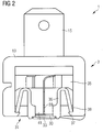
- Figure 2 shows a first sectional view of an embodiment of the contact body 3 in detail.
- the contact body 3 has a bottom wall 31 for applying the contact temperature sensor 1 to the test body 7.
- the contact body 3 comprises a carrier ceramic 33 for direct thermal coupling of the test body 7 to the contact temperature sensor 1.
- the carrier ceramic 33 is arranged on a side of the base wall 31 facing the test body 7.
- the contact body 3 has, for example, a cavity 35 with an opening.
- the opening is arranged in the bottom wall 31 of the contact body 3 and is at least partially covered or closed by the carrier ceramic 33.
- a holding element 36 is arranged at least partially in the cavity 35, for example.
- the holding element 36 is arranged and designed to hold the temperature sensor element 30 and the carrier ceramic 33.
- the retaining element 36 is designed, for example, as a retaining clip.
- the holding element 36 is held in the cavity 35 of the contact body 3, for example, by means of a clamp connection.
- an inner wall of the cavity 35 has latching hooks 37 on which the clip legs 38 of the retaining clips are supported.
- the carrier ceramic 33 is, for example, mechanically coupled to the holding element 36.
- the carrier ceramic 33 preferably has silicon nitride or consists of silicon nitride. Silicon nitride has a high breaking strength.
- the carrier ceramic 33 comprises an alternative or further ceramic material, for example aluminum oxide. That is, the ceramic material can be selected depending on the requirements in terms of breaking strength, thermal conductivity and / or processability.
- the carrier ceramic 33 preferably has a full-surface metallization on the side facing the test body 7 for efficient absorption of the thermal energy of the test body 7.
- the temperature sensor element 30 is preferably thermally and mechanically coupled directly to the carrier ceramic 33.
- the carrier ceramic 33 has a metallization, preferably a structured metallization, on the side facing away from the test body 7.
- the metallization can for example comprise silver or copper or consist of silver or copper.
- the temperature sensor element 30 is coupled to the carrier ceramic 33 via an integral joint connection.
- the cohesive joint connection can comprise a soldered connection.
- the cohesive joint connection can be produced by means of a common sintering of the carrier ceramic 33 with the temperature sensor element 30.
- the temperature sensor element 30 preferably also has a ceramic material. Sintering can be done without pressure or with pressure.
- the temperature sensor element 30 preferably comprises a thermistor, also called an NTC resistor (NTC - Negative Temperature Coefficient).
- the contact temperature sensor 1 comprises at least one contact for electrical coupling with an evaluation device.
- the temperature sensor element 30 and / or the carrier ceramic 33 are each coupled and / or directly connected to the at least one electrical contact via an electrically conductive connecting wire 39.
- the connecting wire 39 preferably has a plating.
- the respective electrically conductive connecting wire 39 has a conductor which, for example, is an iron-nickel alloy includes.
- a copper plating, for example, is applied to the conductor.
- the metallization on the side of the carrier ceramic 33 facing away from the test body 7 and / or the temperature sensor element 30 is preferably connected to the respective electrically conductive connection wire 39 via an integral connection.
- the carrier ceramic 33 and the temperature sensor element 30 preferably have a common potting 41.
- the encapsulation 41 is applied to the carrier ceramic 33 essentially on the side facing away from the test body 7 in such a way that the temperature sensor element 30 and the carrier ceramic 33 on the side facing away from the test body 7, where they are not covered by a plastic of the holding element 36 and / or of the contact body 3 are covered with the potting 41 are covered.
- the encapsulation 41 is preferably designed and arranged in such a way that no moisture can penetrate the temperature sensor element 30 and the carrier ceramic 33 is supported predominantly over the entire surface or over the entire surface on the side of the carrier ceramic 33 facing away from the test body. In this way, bending or breaking of the carrier ceramic 33 and / or the temperature sensor element 30 can be largely prevented and the reliability of the contact temperature sensor 1 is increased.
- FIG. 3 shows a second sectional view of the embodiment of the contact body 3.
Landscapes
- Physics & Mathematics (AREA)
- General Physics & Mathematics (AREA)
- Measuring Temperature Or Quantity Of Heat (AREA)
Claims (11)
- Sonde de température de contact (1) présentant un corps de contact (3), le corps de contact (3) présentant- une paroi de fond (31) destinée à mettre en contact la sonde de température de contact (1) contre une éprouvette (7) ,- une céramique support (33) pour le couplage thermique de l'éprouvette (7) avec une sonde de température de contact, laquelle céramique est disposée sur une face de la paroi de fond (31) orientée vers l'éprouvette (7), la céramique support (33) présentant une métallisation sur une face orientée vers l'éprouvette (7),- un élément capteur de température (30), qui est couplé thermiquement avec la céramique support (33),caractérisée en ce quele couplage thermique de l'éprouvette avec la sonde de température de contact est un couplage thermique direct.
- Sonde de température de contact (1) selon la revendication 1, dans laquelle la céramique support (33) présente une métallisation sur une face orientée à l'opposé de l'éprouvette (7).
- Sonde de température de contact (1) selon la revendication 1 ou 2, dans laquelle la céramique support (33) présente une métallisation sur toute la surface sur la face orientée vers l'éprouvette (7).
- Sonde de température de contact (1) selon la revendication 2 ou 3, dans laquelle la céramique support (33) présente une métallisation structurée sur la face orientée à l'opposé de l'éprouvette (7).
- Sonde de température de contact (1) selon l'une quelconque des revendications précédentes,
dans laquelle la céramique support (33) présente du nitrure de silicium ou est constituée par du nitrure de silicium. - Sonde de température de contact (1) selon l'une quelconque des revendications précédentes,
dans laquelle l'élément capteur de température (30) comprend un conducteur de chaleur. - Sonde de température de contact (1) selon l'une quelconque des revendications précédentes,
dans laquelle l'élément capteur de température (30) est couplé avec la céramique support (33) par l'intermédiaire d'un assemblage par liaison de matière. - Sonde de température de contact (1) selon l'une quelconque des revendications précédentes,
dans laquelle la sonde de température de contact (1) présente au moins un contact pour le couplage électrique avec un instrument d'évaluation et l'élément capteur de température (30) et/ou la céramique support (33) est/sont couplé(e)(s) et/ou connecté(e)(s) directement avec ledit au moins un contact électrique à chaque fois par l'intermédiaire d'un fil de connexion électroconducteur (39) qui présente un plaquage. - Sonde de température de contact (1) selon la revendication 8,
dans laquelle le fil de connexion électroconducteur (39) respectif présente un conducteur qui présente un alliage de fer-nickel et un plaquage de cuivre est appliqué sur le conducteur. - Sonde de température de contact (1) selon l'une quelconque des revendications précédentes,
dans laquelle la métallisation sur la face de la céramique support (33) orientée à l'opposé de l'éprouvette (7) et/ou l'élément capteur de température (30) est/sont relié(e)(s) au fil de connexion électroconducteur (39) respectif par l'intermédiaire d'un assemblage par liaison de matière. - Sonde de température de contact (1) selon l'une quelconque des revendications précédentes,
dans laquelle la céramique support (33) et l'élément capteur de température (30) présentent un scellement commun.
Applications Claiming Priority (2)
| Application Number | Priority Date | Filing Date | Title |
|---|---|---|---|
| DE102017116533.9A DE102017116533A1 (de) | 2017-07-21 | 2017-07-21 | Anlegetemperaturmessfühler |
| PCT/EP2018/068278 WO2019015986A1 (fr) | 2017-07-21 | 2018-07-05 | Capteur de température à contact |
Publications (2)
| Publication Number | Publication Date |
|---|---|
| EP3612806A1 EP3612806A1 (fr) | 2020-02-26 |
| EP3612806B1 true EP3612806B1 (fr) | 2021-09-01 |
Family
ID=62842122
Family Applications (1)
| Application Number | Title | Priority Date | Filing Date |
|---|---|---|---|
| EP18737896.3A Active EP3612806B1 (fr) | 2017-07-21 | 2018-07-05 | Capteur de température à contact |
Country Status (6)
| Country | Link |
|---|---|
| US (1) | US20200149974A1 (fr) |
| EP (1) | EP3612806B1 (fr) |
| JP (1) | JP2020523581A (fr) |
| CN (1) | CN110914657A (fr) |
| DE (1) | DE102017116533A1 (fr) |
| WO (1) | WO2019015986A1 (fr) |
Families Citing this family (4)
| Publication number | Priority date | Publication date | Assignee | Title |
|---|---|---|---|---|
| DE102020115856A1 (de) | 2020-06-16 | 2021-12-16 | Tdk Electronics Ag | Sensoranordnung |
| US11703395B2 (en) * | 2020-12-31 | 2023-07-18 | Endress+Hauser Wetzer Gmbh+Co. Kg | Measurement device for measuring a temperature |
| WO2022235396A1 (fr) * | 2021-05-06 | 2022-11-10 | Therm-O-Disc Incorporated | Ensemble capteur de température |
| DE102021129342B3 (de) | 2021-11-11 | 2023-02-02 | SIKA Dr. Siebert & Kühn GmbH & Co. KG | Verfahren und System zur Bestimmung der Temperatur eines durch einen Leitungskörper strömenden Fluids |
Family Cites Families (30)
| Publication number | Priority date | Publication date | Assignee | Title |
|---|---|---|---|---|
| JPH01229924A (ja) * | 1988-03-09 | 1989-09-13 | Murata Mfg Co Ltd | 温度プローブ |
| JPH03131003A (ja) * | 1989-10-16 | 1991-06-04 | Kobe Steel Ltd | ダイヤモンド薄膜サーミスタ |
| US5707151A (en) * | 1994-01-13 | 1998-01-13 | Ranco Incorporated Of Delaware | Temperature transducer assembly |
| JPH08138906A (ja) * | 1994-11-14 | 1996-05-31 | Tdk Corp | 正特性サーミスタ装置、熱検出装置及び正特性サーミスタ装置の製造方法 |
| JPH08261848A (ja) * | 1995-03-27 | 1996-10-11 | Kurabe Ind Co Ltd | 調理器具類用温度検知器 |
| JP3572312B2 (ja) * | 1996-07-12 | 2004-09-29 | いすゞ自動車株式会社 | セラミックシース型熱電対 |
| EP0908712B1 (fr) * | 1997-09-16 | 2005-06-29 | Siemens Schweiz AG | Capteur de température |
| US6257758B1 (en) * | 1998-10-09 | 2001-07-10 | Claud S. Gordon Company | Surface temperature sensor |
| JP2001215156A (ja) * | 2000-02-02 | 2001-08-10 | Sharp Corp | 接触式温度測定装置 |
| JP2002048655A (ja) * | 2000-05-24 | 2002-02-15 | Ngk Spark Plug Co Ltd | 温度センサ及びその製造管理方法 |
| US6334707B1 (en) * | 2000-07-19 | 2002-01-01 | Second Source Supply Incorporated | Temperature sensing device for test cylinder |
| JP2002188966A (ja) * | 2000-12-22 | 2002-07-05 | Ngk Spark Plug Co Ltd | 温度センサ及びその製造方法並びに製造管理方法 |
| JP2002335060A (ja) * | 2001-05-11 | 2002-11-22 | Matsushita Electric Works Ltd | 回路基板 |
| JP2003004538A (ja) * | 2001-06-20 | 2003-01-08 | Isuzu Ceramics Res Inst Co Ltd | 熱電対保護管 |
| US20060275933A1 (en) * | 2005-06-02 | 2006-12-07 | Applied Materials, Inc. | Thermally conductive ceramic tipped contact thermocouple |
| DE102006025179A1 (de) * | 2006-05-30 | 2007-12-06 | Epcos Ag | Sensoranordnung |
| US7312690B1 (en) * | 2006-12-21 | 2007-12-25 | General Electric Company | Temperature sensor |
| JP2009098042A (ja) * | 2007-10-18 | 2009-05-07 | Mitsuteru Kimura | ダイオード温度センサ素子とこれを用いた温度測定装置 |
| DE102008009817A1 (de) * | 2008-02-19 | 2009-08-27 | Epcos Ag | Verbundwerkstoff zur Temperaturmessung, Temperatursensor aufweisend den Verbundwerkstoff und Verfahren zur Herstellung des Verbundwerkstoffs und des Temperatursensors |
| DE102010052478B4 (de) * | 2010-11-26 | 2013-09-19 | Phoenix Contact Gmbh & Co. Kg | Elektrischer Streckenverbinder für Thermoelemente und Verfahren zu dessen Herstellung |
| JP2015069738A (ja) * | 2013-09-27 | 2015-04-13 | 株式会社オートネットワーク技術研究所 | 温度センサ、及び配線モジュール |
| JP6356498B2 (ja) * | 2014-06-16 | 2018-07-11 | 住友電気工業株式会社 | 測温モジュール、プリント回路板及び測温モジュールの製造方法 |
| DE102014110560A1 (de) * | 2014-07-25 | 2016-01-28 | Epcos Ag | Sensorelement, Sensoranordnung und Verfahren zur Herstellung eines Sensorelements und einer Sensoranordnung |
| DE102015114314A1 (de) * | 2015-08-28 | 2017-03-02 | Innovative Sensor Technology Ist Ag | Verfahren zur Herstellung eines Temperatursensors |
| DE102016101248A1 (de) * | 2015-11-02 | 2017-05-04 | Epcos Ag | Sensorelement und Verfahren zur Herstellung eines Sensorelements |
| JP2017102048A (ja) * | 2015-12-03 | 2017-06-08 | 株式会社オートネットワーク技術研究所 | 温度センサ、及び温度検知モジュール |
| JP6545627B2 (ja) * | 2016-02-19 | 2019-07-17 | 日本特殊陶業株式会社 | 温度センサ |
| CN109313085A (zh) * | 2016-06-30 | 2019-02-05 | 世美特株式会社 | 温度传感器及具有温度传感器的装置 |
| CN206177474U (zh) * | 2016-08-12 | 2017-05-17 | 泰科电子(上海)有限公司 | 测温组件及电器设备 |
| JP6231183B2 (ja) * | 2016-12-09 | 2017-11-15 | 日立オートモティブシステムズ株式会社 | 物理量測定装置 |
-
2017
- 2017-07-21 DE DE102017116533.9A patent/DE102017116533A1/de not_active Withdrawn
-
2018
- 2018-07-05 WO PCT/EP2018/068278 patent/WO2019015986A1/fr not_active Ceased
- 2018-07-05 CN CN201880049060.9A patent/CN110914657A/zh active Pending
- 2018-07-05 EP EP18737896.3A patent/EP3612806B1/fr active Active
- 2018-07-05 JP JP2019568213A patent/JP2020523581A/ja active Pending
- 2018-07-05 US US16/631,078 patent/US20200149974A1/en not_active Abandoned
Also Published As
| Publication number | Publication date |
|---|---|
| WO2019015986A1 (fr) | 2019-01-24 |
| CN110914657A (zh) | 2020-03-24 |
| US20200149974A1 (en) | 2020-05-14 |
| EP3612806A1 (fr) | 2020-02-26 |
| DE102017116533A1 (de) | 2019-01-24 |
| JP2020523581A (ja) | 2020-08-06 |
Similar Documents
| Publication | Publication Date | Title |
|---|---|---|
| EP3526564B1 (fr) | Sonde de température d'application | |
| EP3612806B1 (fr) | Capteur de température à contact | |
| DE102006034248B3 (de) | Temperaturfühler für ein Widerstandsthermometer, insbesondere zur Verwendung im Abgasstrang von Verbrennungsmotoren | |
| CH652533A5 (de) | Halbleiterbaustein. | |
| EP0801150A2 (fr) | Composant électronique | |
| WO2014037257A2 (fr) | Dispositif de mesure de température pour déterminer la température à la surface d'une canalisation | |
| DE102004057421A1 (de) | Druckkontaktiertes Leistungshalbleitermodul für hohe Umgebungstemperaturen und Verfahren zu seiner Herstellung | |
| WO2001096850A1 (fr) | Capteur de mesure de gaz | |
| DE2938086C2 (de) | Temperaturfühler zur Ermittlung der Kühlmitteltemperatur bei flüssigkeitsgekühlten Transformatoren | |
| EP3245672B1 (fr) | Agencement de contacts et module de puissance | |
| EP3853873B1 (fr) | Composant résistif pour montage en surface sur une carte de circuit imprimé et carte de circuit imprimé avec au moins un composant résistif agencé sur celle-ci | |
| EP0718738A2 (fr) | Elément fonctionnel thermostatique avec un élément chauffant à résistance électrique | |
| WO2019029942A1 (fr) | Module de détection | |
| DE10205408A1 (de) | Halbleitermodul | |
| DE102014221142A1 (de) | Modul mit Sinteranbindung | |
| DE102006003602B4 (de) | Oberflächensensor, Sensoranordnung und Klimaanlage | |
| DE102020212773A1 (de) | Leistungsmodul | |
| DE19816941A1 (de) | Temperatursensor und Verfahren zu seiner Herstellung | |
| EP3054480B1 (fr) | Systeme de contact et module de puissance | |
| EP3118614B1 (fr) | Élement de capteur ceramique de temperature et de gaz | |
| DE102007041096A1 (de) | Elektrische Baugruppe mit einem elektrischen Bauelement, einer Wärmesenke und einem Wärmeleitelement zwischen Bauelement und Wärmesenke | |
| WO2008145512A2 (fr) | Dispositif permettant de déterminer et/ou de surveiller une grandeur de traitement | |
| DE102016213140A1 (de) | Träger, der mit mindestens einem Leistungshalbleiterbauelement bestückt ist | |
| EP1014060B1 (fr) | Dispositif de mesure de la température | |
| DE102018104690A1 (de) | Sensorträgereinheit sowie Heizungskomponente |
Legal Events
| Date | Code | Title | Description |
|---|---|---|---|
| STAA | Information on the status of an ep patent application or granted ep patent |
Free format text: STATUS: UNKNOWN |
|
| STAA | Information on the status of an ep patent application or granted ep patent |
Free format text: STATUS: THE INTERNATIONAL PUBLICATION HAS BEEN MADE |
|
| PUAI | Public reference made under article 153(3) epc to a published international application that has entered the european phase |
Free format text: ORIGINAL CODE: 0009012 |
|
| STAA | Information on the status of an ep patent application or granted ep patent |
Free format text: STATUS: REQUEST FOR EXAMINATION WAS MADE |
|
| 17P | Request for examination filed |
Effective date: 20190927 |
|
| AK | Designated contracting states |
Kind code of ref document: A1 Designated state(s): AL AT BE BG CH CY CZ DE DK EE ES FI FR GB GR HR HU IE IS IT LI LT LU LV MC MK MT NL NO PL PT RO RS SE SI SK SM TR |
|
| AX | Request for extension of the european patent |
Extension state: BA ME |
|
| DAV | Request for validation of the european patent (deleted) | ||
| DAX | Request for extension of the european patent (deleted) | ||
| GRAP | Despatch of communication of intention to grant a patent |
Free format text: ORIGINAL CODE: EPIDOSNIGR1 |
|
| STAA | Information on the status of an ep patent application or granted ep patent |
Free format text: STATUS: GRANT OF PATENT IS INTENDED |
|
| INTG | Intention to grant announced |
Effective date: 20210318 |
|
| GRAS | Grant fee paid |
Free format text: ORIGINAL CODE: EPIDOSNIGR3 |
|
| GRAA | (expected) grant |
Free format text: ORIGINAL CODE: 0009210 |
|
| STAA | Information on the status of an ep patent application or granted ep patent |
Free format text: STATUS: THE PATENT HAS BEEN GRANTED |
|
| RIN1 | Information on inventor provided before grant (corrected) |
Inventor name: SCHMIDT, MICHAEL Inventor name: HAND, THOMAS |
|
| AK | Designated contracting states |
Kind code of ref document: B1 Designated state(s): AL AT BE BG CH CY CZ DE DK EE ES FI FR GB GR HR HU IE IS IT LI LT LU LV MC MK MT NL NO PL PT RO RS SE SI SK SM TR |
|
| REG | Reference to a national code |
Ref country code: GB Ref legal event code: FG4D Free format text: NOT ENGLISH |
|
| REG | Reference to a national code |
Ref country code: CH Ref legal event code: EP Ref country code: AT Ref legal event code: REF Ref document number: 1426700 Country of ref document: AT Kind code of ref document: T Effective date: 20210915 |
|
| REG | Reference to a national code |
Ref country code: DE Ref legal event code: R096 Ref document number: 502018006859 Country of ref document: DE |
|
| REG | Reference to a national code |
Ref country code: IE Ref legal event code: FG4D Free format text: LANGUAGE OF EP DOCUMENT: GERMAN |
|
| REG | Reference to a national code |
Ref country code: LT Ref legal event code: MG9D |
|
| REG | Reference to a national code |
Ref country code: NL Ref legal event code: MP Effective date: 20210901 |
|
| PG25 | Lapsed in a contracting state [announced via postgrant information from national office to epo] |
Ref country code: NO Free format text: LAPSE BECAUSE OF FAILURE TO SUBMIT A TRANSLATION OF THE DESCRIPTION OR TO PAY THE FEE WITHIN THE PRESCRIBED TIME-LIMIT Effective date: 20211201 Ref country code: LT Free format text: LAPSE BECAUSE OF FAILURE TO SUBMIT A TRANSLATION OF THE DESCRIPTION OR TO PAY THE FEE WITHIN THE PRESCRIBED TIME-LIMIT Effective date: 20210901 Ref country code: BG Free format text: LAPSE BECAUSE OF FAILURE TO SUBMIT A TRANSLATION OF THE DESCRIPTION OR TO PAY THE FEE WITHIN THE PRESCRIBED TIME-LIMIT Effective date: 20211201 Ref country code: SE Free format text: LAPSE BECAUSE OF FAILURE TO SUBMIT A TRANSLATION OF THE DESCRIPTION OR TO PAY THE FEE WITHIN THE PRESCRIBED TIME-LIMIT Effective date: 20210901 Ref country code: RS Free format text: LAPSE BECAUSE OF FAILURE TO SUBMIT A TRANSLATION OF THE DESCRIPTION OR TO PAY THE FEE WITHIN THE PRESCRIBED TIME-LIMIT Effective date: 20210901 Ref country code: HR Free format text: LAPSE BECAUSE OF FAILURE TO SUBMIT A TRANSLATION OF THE DESCRIPTION OR TO PAY THE FEE WITHIN THE PRESCRIBED TIME-LIMIT Effective date: 20210901 Ref country code: ES Free format text: LAPSE BECAUSE OF FAILURE TO SUBMIT A TRANSLATION OF THE DESCRIPTION OR TO PAY THE FEE WITHIN THE PRESCRIBED TIME-LIMIT Effective date: 20210901 Ref country code: FI Free format text: LAPSE BECAUSE OF FAILURE TO SUBMIT A TRANSLATION OF THE DESCRIPTION OR TO PAY THE FEE WITHIN THE PRESCRIBED TIME-LIMIT Effective date: 20210901 |
|
| PG25 | Lapsed in a contracting state [announced via postgrant information from national office to epo] |
Ref country code: PL Free format text: LAPSE BECAUSE OF FAILURE TO SUBMIT A TRANSLATION OF THE DESCRIPTION OR TO PAY THE FEE WITHIN THE PRESCRIBED TIME-LIMIT Effective date: 20210901 Ref country code: LV Free format text: LAPSE BECAUSE OF FAILURE TO SUBMIT A TRANSLATION OF THE DESCRIPTION OR TO PAY THE FEE WITHIN THE PRESCRIBED TIME-LIMIT Effective date: 20210901 Ref country code: GR Free format text: LAPSE BECAUSE OF FAILURE TO SUBMIT A TRANSLATION OF THE DESCRIPTION OR TO PAY THE FEE WITHIN THE PRESCRIBED TIME-LIMIT Effective date: 20211202 |
|
| PG25 | Lapsed in a contracting state [announced via postgrant information from national office to epo] |
Ref country code: IS Free format text: LAPSE BECAUSE OF FAILURE TO SUBMIT A TRANSLATION OF THE DESCRIPTION OR TO PAY THE FEE WITHIN THE PRESCRIBED TIME-LIMIT Effective date: 20220101 Ref country code: SM Free format text: LAPSE BECAUSE OF FAILURE TO SUBMIT A TRANSLATION OF THE DESCRIPTION OR TO PAY THE FEE WITHIN THE PRESCRIBED TIME-LIMIT Effective date: 20210901 Ref country code: SK Free format text: LAPSE BECAUSE OF FAILURE TO SUBMIT A TRANSLATION OF THE DESCRIPTION OR TO PAY THE FEE WITHIN THE PRESCRIBED TIME-LIMIT Effective date: 20210901 Ref country code: RO Free format text: LAPSE BECAUSE OF FAILURE TO SUBMIT A TRANSLATION OF THE DESCRIPTION OR TO PAY THE FEE WITHIN THE PRESCRIBED TIME-LIMIT Effective date: 20210901 Ref country code: PT Free format text: LAPSE BECAUSE OF FAILURE TO SUBMIT A TRANSLATION OF THE DESCRIPTION OR TO PAY THE FEE WITHIN THE PRESCRIBED TIME-LIMIT Effective date: 20220103 Ref country code: NL Free format text: LAPSE BECAUSE OF FAILURE TO SUBMIT A TRANSLATION OF THE DESCRIPTION OR TO PAY THE FEE WITHIN THE PRESCRIBED TIME-LIMIT Effective date: 20210901 Ref country code: EE Free format text: LAPSE BECAUSE OF FAILURE TO SUBMIT A TRANSLATION OF THE DESCRIPTION OR TO PAY THE FEE WITHIN THE PRESCRIBED TIME-LIMIT Effective date: 20210901 Ref country code: CZ Free format text: LAPSE BECAUSE OF FAILURE TO SUBMIT A TRANSLATION OF THE DESCRIPTION OR TO PAY THE FEE WITHIN THE PRESCRIBED TIME-LIMIT Effective date: 20210901 Ref country code: AL Free format text: LAPSE BECAUSE OF FAILURE TO SUBMIT A TRANSLATION OF THE DESCRIPTION OR TO PAY THE FEE WITHIN THE PRESCRIBED TIME-LIMIT Effective date: 20210901 |
|
| REG | Reference to a national code |
Ref country code: DE Ref legal event code: R097 Ref document number: 502018006859 Country of ref document: DE |
|
| PLBE | No opposition filed within time limit |
Free format text: ORIGINAL CODE: 0009261 |
|
| STAA | Information on the status of an ep patent application or granted ep patent |
Free format text: STATUS: NO OPPOSITION FILED WITHIN TIME LIMIT |
|
| PG25 | Lapsed in a contracting state [announced via postgrant information from national office to epo] |
Ref country code: IT Free format text: LAPSE BECAUSE OF FAILURE TO SUBMIT A TRANSLATION OF THE DESCRIPTION OR TO PAY THE FEE WITHIN THE PRESCRIBED TIME-LIMIT Effective date: 20210901 Ref country code: DK Free format text: LAPSE BECAUSE OF FAILURE TO SUBMIT A TRANSLATION OF THE DESCRIPTION OR TO PAY THE FEE WITHIN THE PRESCRIBED TIME-LIMIT Effective date: 20210901 |
|
| 26N | No opposition filed |
Effective date: 20220602 |
|
| PG25 | Lapsed in a contracting state [announced via postgrant information from national office to epo] |
Ref country code: SI Free format text: LAPSE BECAUSE OF FAILURE TO SUBMIT A TRANSLATION OF THE DESCRIPTION OR TO PAY THE FEE WITHIN THE PRESCRIBED TIME-LIMIT Effective date: 20210901 |
|
| PG25 | Lapsed in a contracting state [announced via postgrant information from national office to epo] |
Ref country code: MC Free format text: LAPSE BECAUSE OF FAILURE TO SUBMIT A TRANSLATION OF THE DESCRIPTION OR TO PAY THE FEE WITHIN THE PRESCRIBED TIME-LIMIT Effective date: 20210901 |
|
| REG | Reference to a national code |
Ref country code: CH Ref legal event code: PL |
|
| GBPC | Gb: european patent ceased through non-payment of renewal fee |
Effective date: 20220705 |
|
| REG | Reference to a national code |
Ref country code: BE Ref legal event code: MM Effective date: 20220731 |
|
| PG25 | Lapsed in a contracting state [announced via postgrant information from national office to epo] |
Ref country code: LU Free format text: LAPSE BECAUSE OF NON-PAYMENT OF DUE FEES Effective date: 20220705 Ref country code: LI Free format text: LAPSE BECAUSE OF NON-PAYMENT OF DUE FEES Effective date: 20220731 Ref country code: FR Free format text: LAPSE BECAUSE OF NON-PAYMENT OF DUE FEES Effective date: 20220731 Ref country code: CH Free format text: LAPSE BECAUSE OF NON-PAYMENT OF DUE FEES Effective date: 20220731 |
|
| PG25 | Lapsed in a contracting state [announced via postgrant information from national office to epo] |
Ref country code: GB Free format text: LAPSE BECAUSE OF NON-PAYMENT OF DUE FEES Effective date: 20220705 Ref country code: BE Free format text: LAPSE BECAUSE OF NON-PAYMENT OF DUE FEES Effective date: 20220731 |
|
| P01 | Opt-out of the competence of the unified patent court (upc) registered |
Effective date: 20230521 |
|
| PG25 | Lapsed in a contracting state [announced via postgrant information from national office to epo] |
Ref country code: IE Free format text: LAPSE BECAUSE OF NON-PAYMENT OF DUE FEES Effective date: 20220705 |
|
| PG25 | Lapsed in a contracting state [announced via postgrant information from national office to epo] |
Ref country code: HU Free format text: LAPSE BECAUSE OF FAILURE TO SUBMIT A TRANSLATION OF THE DESCRIPTION OR TO PAY THE FEE WITHIN THE PRESCRIBED TIME-LIMIT; INVALID AB INITIO Effective date: 20180705 |
|
| PG25 | Lapsed in a contracting state [announced via postgrant information from national office to epo] |
Ref country code: MK Free format text: LAPSE BECAUSE OF FAILURE TO SUBMIT A TRANSLATION OF THE DESCRIPTION OR TO PAY THE FEE WITHIN THE PRESCRIBED TIME-LIMIT Effective date: 20210901 Ref country code: CY Free format text: LAPSE BECAUSE OF FAILURE TO SUBMIT A TRANSLATION OF THE DESCRIPTION OR TO PAY THE FEE WITHIN THE PRESCRIBED TIME-LIMIT Effective date: 20210901 |
|
| PG25 | Lapsed in a contracting state [announced via postgrant information from national office to epo] |
Ref country code: TR Free format text: LAPSE BECAUSE OF FAILURE TO SUBMIT A TRANSLATION OF THE DESCRIPTION OR TO PAY THE FEE WITHIN THE PRESCRIBED TIME-LIMIT Effective date: 20210901 |
|
| REG | Reference to a national code |
Ref country code: AT Ref legal event code: MM01 Ref document number: 1426700 Country of ref document: AT Kind code of ref document: T Effective date: 20230705 |
|
| PG25 | Lapsed in a contracting state [announced via postgrant information from national office to epo] |
Ref country code: MT Free format text: LAPSE BECAUSE OF FAILURE TO SUBMIT A TRANSLATION OF THE DESCRIPTION OR TO PAY THE FEE WITHIN THE PRESCRIBED TIME-LIMIT Effective date: 20210901 |
|
| PG25 | Lapsed in a contracting state [announced via postgrant information from national office to epo] |
Ref country code: AT Free format text: LAPSE BECAUSE OF NON-PAYMENT OF DUE FEES Effective date: 20230705 |
|
| PG25 | Lapsed in a contracting state [announced via postgrant information from national office to epo] |
Ref country code: AT Free format text: LAPSE BECAUSE OF NON-PAYMENT OF DUE FEES Effective date: 20230705 |
|
| PGFP | Annual fee paid to national office [announced via postgrant information from national office to epo] |
Ref country code: DE Payment date: 20250723 Year of fee payment: 8 |
|
| PGFP | Annual fee paid to national office [announced via postgrant information from national office to epo] |
Ref country code: AT Payment date: 20260410 Year of fee payment: 5 |