EP3612847B1 - Fahrzeug und steuerungsverfahren dafür und system - Google Patents
Fahrzeug und steuerungsverfahren dafür und system Download PDFInfo
- Publication number
- EP3612847B1 EP3612847B1 EP18787396.3A EP18787396A EP3612847B1 EP 3612847 B1 EP3612847 B1 EP 3612847B1 EP 18787396 A EP18787396 A EP 18787396A EP 3612847 B1 EP3612847 B1 EP 3612847B1
- Authority
- EP
- European Patent Office
- Prior art keywords
- current
- electric machine
- stator
- inverter
- vehicle
- Prior art date
- Legal status (The legal status is an assumption and is not a legal conclusion. Google has not performed a legal analysis and makes no representation as to the accuracy of the status listed.)
- Active
Links
Images



Classifications
-
- H—ELECTRICITY
- H02—GENERATION; CONVERSION OR DISTRIBUTION OF ELECTRIC POWER
- H02P—CONTROL OR REGULATION OF ELECTRIC MOTORS, ELECTRIC GENERATORS OR DYNAMO-ELECTRIC CONVERTERS; CONTROLLING TRANSFORMERS, REACTORS OR CHOKE COILS
- H02P23/00—Arrangements or methods for the control of AC motors characterised by a control method other than vector control
-
- H—ELECTRICITY
- H02—GENERATION; CONVERSION OR DISTRIBUTION OF ELECTRIC POWER
- H02M—APPARATUS FOR CONVERSION BETWEEN AC AND AC, BETWEEN AC AND DC, OR BETWEEN DC AND DC, AND FOR USE WITH MAINS OR SIMILAR POWER SUPPLY SYSTEMS; CONVERSION OF DC OR AC INPUT POWER INTO SURGE OUTPUT POWER; CONTROL OR REGULATION THEREOF
- H02M7/00—Conversion of AC power input into DC power output; Conversion of DC power input into AC power output
- H02M7/42—Conversion of DC power input into AC power output without possibility of reversal
- H02M7/44—Conversion of DC power input into AC power output without possibility of reversal by static converters
- H02M7/48—Conversion of DC power input into AC power output without possibility of reversal by static converters using discharge tubes with control electrode or semiconductor devices with control electrode
- H02M7/53—Conversion of DC power input into AC power output without possibility of reversal by static converters using discharge tubes with control electrode or semiconductor devices with control electrode using devices of a triode or transistor type requiring continuous application of a control signal
- H02M7/537—Conversion of DC power input into AC power output without possibility of reversal by static converters using discharge tubes with control electrode or semiconductor devices with control electrode using devices of a triode or transistor type requiring continuous application of a control signal using semiconductor devices only, e.g. single switched pulse inverters
- H02M7/5387—Conversion of DC power input into AC power output without possibility of reversal by static converters using discharge tubes with control electrode or semiconductor devices with control electrode using devices of a triode or transistor type requiring continuous application of a control signal using semiconductor devices only, e.g. single switched pulse inverters in a bridge configuration
- H02M7/53871—Conversion of DC power input into AC power output without possibility of reversal by static converters using discharge tubes with control electrode or semiconductor devices with control electrode using devices of a triode or transistor type requiring continuous application of a control signal using semiconductor devices only, e.g. single switched pulse inverters in a bridge configuration with automatic control of output voltage or current
- H02M7/53875—Conversion of DC power input into AC power output without possibility of reversal by static converters using discharge tubes with control electrode or semiconductor devices with control electrode using devices of a triode or transistor type requiring continuous application of a control signal using semiconductor devices only, e.g. single switched pulse inverters in a bridge configuration with automatic control of output voltage or current with analogue control of three-phase output
-
- B—PERFORMING OPERATIONS; TRANSPORTING
- B60—VEHICLES IN GENERAL
- B60L—PROPULSION OF ELECTRICALLY-PROPELLED VEHICLES; SUPPLYING ELECTRIC POWER FOR AUXILIARY EQUIPMENT OF ELECTRICALLY-PROPELLED VEHICLES; ELECTRODYNAMIC BRAKE SYSTEMS FOR VEHICLES IN GENERAL; MAGNETIC SUSPENSION OR LEVITATION FOR VEHICLES; MONITORING OPERATING VARIABLES OF ELECTRICALLY-PROPELLED VEHICLES; ELECTRIC SAFETY DEVICES FOR ELECTRICALLY-PROPELLED VEHICLES
- B60L3/00—Electric devices on electrically-propelled vehicles for safety purposes; Monitoring operating variables, e.g. speed, deceleration or energy consumption
- B60L3/0023—Detecting, eliminating, remedying or compensating for drive train abnormalities, e.g. failures within the drive train
- B60L3/003—Detecting, eliminating, remedying or compensating for drive train abnormalities, e.g. failures within the drive train relating to inverters
-
- B—PERFORMING OPERATIONS; TRANSPORTING
- B60—VEHICLES IN GENERAL
- B60L—PROPULSION OF ELECTRICALLY-PROPELLED VEHICLES; SUPPLYING ELECTRIC POWER FOR AUXILIARY EQUIPMENT OF ELECTRICALLY-PROPELLED VEHICLES; ELECTRODYNAMIC BRAKE SYSTEMS FOR VEHICLES IN GENERAL; MAGNETIC SUSPENSION OR LEVITATION FOR VEHICLES; MONITORING OPERATING VARIABLES OF ELECTRICALLY-PROPELLED VEHICLES; ELECTRIC SAFETY DEVICES FOR ELECTRICALLY-PROPELLED VEHICLES
- B60L50/00—Electric propulsion with power supplied within the vehicle
- B60L50/50—Electric propulsion with power supplied within the vehicle using propulsion power supplied by batteries or fuel cells
- B60L50/51—Electric propulsion with power supplied within the vehicle using propulsion power supplied by batteries or fuel cells characterised by AC-motors
-
- B—PERFORMING OPERATIONS; TRANSPORTING
- B60—VEHICLES IN GENERAL
- B60R—VEHICLES, VEHICLE FITTINGS, OR VEHICLE PARTS, NOT OTHERWISE PROVIDED FOR
- B60R16/00—Electric or fluid circuits specially adapted for vehicles and not otherwise provided for; Arrangement of elements of electric or fluid circuits specially adapted for vehicles and not otherwise provided for
- B60R16/02—Electric or fluid circuits specially adapted for vehicles and not otherwise provided for; Arrangement of elements of electric or fluid circuits specially adapted for vehicles and not otherwise provided for electric constitutive elements
-
- G—PHYSICS
- G01—MEASURING; TESTING
- G01R—MEASURING ELECTRIC VARIABLES; MEASURING MAGNETIC VARIABLES
- G01R31/00—Arrangements for testing electric properties; Arrangements for locating electric faults; Arrangements for electrical testing characterised by what is being tested not provided for elsewhere
- G01R31/005—Testing of electric installations on transport means
- G01R31/006—Testing of electric installations on transport means on road vehicles, e.g. automobiles or trucks
-
- G—PHYSICS
- G01—MEASURING; TESTING
- G01R—MEASURING ELECTRIC VARIABLES; MEASURING MAGNETIC VARIABLES
- G01R31/00—Arrangements for testing electric properties; Arrangements for locating electric faults; Arrangements for electrical testing characterised by what is being tested not provided for elsewhere
- G01R31/34—Testing dynamo-electric machines
- G01R31/343—Testing dynamo-electric machines in operation
-
- G—PHYSICS
- G01—MEASURING; TESTING
- G01R—MEASURING ELECTRIC VARIABLES; MEASURING MAGNETIC VARIABLES
- G01R31/00—Arrangements for testing electric properties; Arrangements for locating electric faults; Arrangements for electrical testing characterised by what is being tested not provided for elsewhere
- G01R31/36—Arrangements for testing, measuring or monitoring the electrical condition of accumulators or electric batteries, e.g. capacity or state of charge [SoC]
-
- H—ELECTRICITY
- H02—GENERATION; CONVERSION OR DISTRIBUTION OF ELECTRIC POWER
- H02M—APPARATUS FOR CONVERSION BETWEEN AC AND AC, BETWEEN AC AND DC, OR BETWEEN DC AND DC, AND FOR USE WITH MAINS OR SIMILAR POWER SUPPLY SYSTEMS; CONVERSION OF DC OR AC INPUT POWER INTO SURGE OUTPUT POWER; CONTROL OR REGULATION THEREOF
- H02M1/00—Details of apparatus for conversion
- H02M1/32—Means for protecting converters other than automatic disconnection
-
- H—ELECTRICITY
- H02—GENERATION; CONVERSION OR DISTRIBUTION OF ELECTRIC POWER
- H02P—CONTROL OR REGULATION OF ELECTRIC MOTORS, ELECTRIC GENERATORS OR DYNAMO-ELECTRIC CONVERTERS; CONTROLLING TRANSFORMERS, REACTORS OR CHOKE COILS
- H02P27/00—Arrangements or methods for the control of AC motors characterised by the kind of supply voltage
- H02P27/04—Arrangements or methods for the control of AC motors characterised by the kind of supply voltage using variable-frequency supply voltage, e.g. inverter or converter supply voltage
- H02P27/06—Arrangements or methods for the control of AC motors characterised by the kind of supply voltage using variable-frequency supply voltage, e.g. inverter or converter supply voltage using DC to AC converters or inverters
-
- H—ELECTRICITY
- H02—GENERATION; CONVERSION OR DISTRIBUTION OF ELECTRIC POWER
- H02P—CONTROL OR REGULATION OF ELECTRIC MOTORS, ELECTRIC GENERATORS OR DYNAMO-ELECTRIC CONVERTERS; CONTROLLING TRANSFORMERS, REACTORS OR CHOKE COILS
- H02P29/00—Arrangements for regulating or controlling electric motors, appropriate for both AC and DC motors
- H02P29/02—Providing protection against overload without automatic interruption of supply
- H02P29/024—Detecting a fault condition, e.g. short circuit, locked rotor, open circuit or loss of load
- H02P29/0241—Detecting a fault condition, e.g. short circuit, locked rotor, open circuit or loss of load the fault being an overvoltage
-
- H—ELECTRICITY
- H02—GENERATION; CONVERSION OR DISTRIBUTION OF ELECTRIC POWER
- H02P—CONTROL OR REGULATION OF ELECTRIC MOTORS, ELECTRIC GENERATORS OR DYNAMO-ELECTRIC CONVERTERS; CONTROLLING TRANSFORMERS, REACTORS OR CHOKE COILS
- H02P29/00—Arrangements for regulating or controlling electric motors, appropriate for both AC and DC motors
- H02P29/02—Providing protection against overload without automatic interruption of supply
- H02P29/032—Preventing damage to the motor, e.g. setting individual current limits for different drive conditions
-
- H—ELECTRICITY
- H02—GENERATION; CONVERSION OR DISTRIBUTION OF ELECTRIC POWER
- H02P—CONTROL OR REGULATION OF ELECTRIC MOTORS, ELECTRIC GENERATORS OR DYNAMO-ELECTRIC CONVERTERS; CONTROLLING TRANSFORMERS, REACTORS OR CHOKE COILS
- H02P29/00—Arrangements for regulating or controlling electric motors, appropriate for both AC and DC motors
- H02P29/10—Arrangements for regulating or controlling electric motors, appropriate for both AC and DC motors for preventing overspeed or under speed
-
- H—ELECTRICITY
- H02—GENERATION; CONVERSION OR DISTRIBUTION OF ELECTRIC POWER
- H02M—APPARATUS FOR CONVERSION BETWEEN AC AND AC, BETWEEN AC AND DC, OR BETWEEN DC AND DC, AND FOR USE WITH MAINS OR SIMILAR POWER SUPPLY SYSTEMS; CONVERSION OF DC OR AC INPUT POWER INTO SURGE OUTPUT POWER; CONTROL OR REGULATION THEREOF
- H02M1/00—Details of apparatus for conversion
- H02M1/32—Means for protecting converters other than automatic disconnection
- H02M1/325—Means for protecting converters other than automatic disconnection with means for allowing continuous operation despite a fault, i.e. fault tolerant converters
-
- Y—GENERAL TAGGING OF NEW TECHNOLOGICAL DEVELOPMENTS; GENERAL TAGGING OF CROSS-SECTIONAL TECHNOLOGIES SPANNING OVER SEVERAL SECTIONS OF THE IPC; TECHNICAL SUBJECTS COVERED BY FORMER USPC CROSS-REFERENCE ART COLLECTIONS [XRACs] AND DIGESTS
- Y02—TECHNOLOGIES OR APPLICATIONS FOR MITIGATION OR ADAPTATION AGAINST CLIMATE CHANGE
- Y02T—CLIMATE CHANGE MITIGATION TECHNOLOGIES RELATED TO TRANSPORTATION
- Y02T10/00—Road transport of goods or passengers
- Y02T10/60—Other road transportation technologies with climate change mitigation effect
- Y02T10/64—Electric machine technologies in electromobility
-
- Y—GENERAL TAGGING OF NEW TECHNOLOGICAL DEVELOPMENTS; GENERAL TAGGING OF CROSS-SECTIONAL TECHNOLOGIES SPANNING OVER SEVERAL SECTIONS OF THE IPC; TECHNICAL SUBJECTS COVERED BY FORMER USPC CROSS-REFERENCE ART COLLECTIONS [XRACs] AND DIGESTS
- Y02—TECHNOLOGIES OR APPLICATIONS FOR MITIGATION OR ADAPTATION AGAINST CLIMATE CHANGE
- Y02T—CLIMATE CHANGE MITIGATION TECHNOLOGIES RELATED TO TRANSPORTATION
- Y02T10/00—Road transport of goods or passengers
- Y02T10/60—Other road transportation technologies with climate change mitigation effect
- Y02T10/70—Energy storage systems for electromobility, e.g. batteries
-
- Y—GENERAL TAGGING OF NEW TECHNOLOGICAL DEVELOPMENTS; GENERAL TAGGING OF CROSS-SECTIONAL TECHNOLOGIES SPANNING OVER SEVERAL SECTIONS OF THE IPC; TECHNICAL SUBJECTS COVERED BY FORMER USPC CROSS-REFERENCE ART COLLECTIONS [XRACs] AND DIGESTS
- Y02—TECHNOLOGIES OR APPLICATIONS FOR MITIGATION OR ADAPTATION AGAINST CLIMATE CHANGE
- Y02T—CLIMATE CHANGE MITIGATION TECHNOLOGIES RELATED TO TRANSPORTATION
- Y02T10/00—Road transport of goods or passengers
- Y02T10/60—Other road transportation technologies with climate change mitigation effect
- Y02T10/72—Electric energy management in electromobility
Definitions
- the present disclosure generally relates to the field of control, and in particular, to a vehicle capable of fault-tolerant control when a fault occurs in an inverter during running of the vehicle and a control method thereof, and a system capable of fault-tolerant control when a fault occurs in an inverter during running of an AC electric machine.
- an inverter is generally used to convert DC power from the power storage device into AC power for driving a rotating electric machine such as a motor generator.
- a rotating electric machine such as a motor generator.
- driving force generated by the rotating electric machine is used to drive a vehicle, braking force from driving wheels of the vehicle, the engine, and the like can be converted into electric energy to charge the power storage device during regenerative braking.
- a common fault for the inverter is an open circuit fault occurring in a transistor in the inverter. It is well-known that a motor at a high speed, such as a permanent magnetic motor, will cause excessively high counter electromotive force when an inverter broke down. In this case, a peak current and high torque ripple on a stator side of the motor will occur.
- One of existing vehicle control methods usually stops the inverter directly after the inverter fails. However, if the inverter is stopped, the power storage device cannot provide driving force for the rotating electric machine via the inverter. Consequently, in an electric vehicle that loses driving force of a rotating electric machine, the vehicle can only run by inertia, and when inertial running is completed and the vehicle stops, the vehicle cannot drive by its own power. As a result, it is possible to cause traffic jams because the vehicle cannot move on the road, or the vehicle cannot arrive at a repair place, but have to use a trailer.
- EP 2 048 774 A2 which relates to a rotary electric system with star-connected multiphase windings. A half wave-driving mode allows a controller to drive any one of a high side switching element and a low-side switching element per phase of multiphase stator windings.
- An aspect of the present invention provides a vehicle according to claim 1.
- Another aspect of the present invention provides a control method of a vehicle according to claim 9. Further preferred features are defined in the dependent claims.
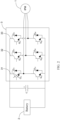
- FIG. 1 shows a schematic block diagram of an electric machine drive system of a vehicle according to a specific example of the present disclosure.
- the vehicle includes an AC electric machine 1 configured to generate traction driving force.
- the vehicle may include but is not limited to an electric vehicle, hybrid electric vehicle, and the like.
- the AC electric machine 1 may include, for example, an interior permanent magnet motor (IPM) or an induction motor (IM).
- IPM interior permanent magnet motor
- IM induction motor
- the IPM is shown as an example.
- the AC electric machine 1 may be, for example, a three-phase AC motor.
- the vehicle further includes a DC bus (DC bus, in this specific example of the present disclosure, a battery 2 is shown as an illustrative example) configured to provide a DC voltage U dc , an inverter 3, and a controller 4.
- the inverter 3 is coupled with the battery 2 and configured to convert the DC (Direct Current) voltage from the battery 2 to an AC (Alternating Current) voltage to drive the AC electric machine 1.
- a capacitor C is connected in parallel between the battery 2 and the inverter 3.
- the inverter 3 includes a plurality of transistors.
- the inverter 3 may be, for example, a three-phase inverter, and includes three bridge arms 31, 32, and 33.
- Each bridge arm has two transistors in series and two diodes, and each transistor is connected in anti-parallel with one diode.
- the bridge arm 31 includes two transistors Q 11 , Q 12 in series and two diodes D 11 , D 12 connected in anti-parallel with the transistors Q 11 , Q 12 ;
- the bridge arm 32 includes two transistors Q 21 , Q 22 in series and two diodes D 21 , D 22 connected in anti-parallel with the transistors Q 21 , Q 22 ;
- the bridge arm 33 includes two transistors Q 31 , Q 32 in series and two diodes D 31 , D 32 connected in anti-parallel with the transistors Q 31 , Q 32 .
- Each phase of the three-phase electric machine 1 is connected to connection points of two transistors in series in one of the bridge arms 31, 32, and 33 of the inverter 3.
- the controller 4 can control the inverter 3 to maintain driving force of the vehicle in a fault-tolerant manner, so as to control the vehicle to drive in such a mode as a limp-home mode or the like.
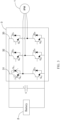
- the case in which an open circuit fault occurs in one of the transistors in the inverter 3 mentioned in the present disclosure at least includes: an open circuit fault occurs in only one transistor (for example, transistor Q 11 ) in the inverter 3 shown in FIG. 2 , and an open circuit fault occurs in both one of the transistors (for example, transistor Q 11 ) and a diode (for example, diode D 11 ) connected to the transistor in anti-parallel.
- the controller 4 of the present disclosure removes a gate driver signal provided to all the transistors of the inverter 3.
- the vehicle can only regeneratively brake, and the vehicle can reduce the vehicle speed by inertial driving or regenerative braking.
- the controller 4 removes the gate driver signal on all the transistors, the inverter 3 acts as a diode rectifier. When the diode is in ON state, a battery 1 is connected to a stator of the AC electric machine 1.
- a DC voltage U dc provided by the battery 1 may reduce an effect of counter electromotive force of the AC electric machine 1 on the stator current of the AC electric machine 1, and the current stress on the stator of the AC electric machine 1 can be reduced.
- An actual vehicle speed V act may be obtained according to a rotational speed V motor of the AC electric machine 1.
- the rotational speed V motor of the AC electric machine 1 may be measured by a speed sensor (not shown), and the rotational speed V motor of the AC electric machine 1 is transferred to the controller 4, and the controller 4 can calculate the current actual vehicle speed V act based on the rotational speed V motor of the AC electric machine 1.
- the predetermined speed threshold V th is relevant to the DC voltage U dc provided by the battery 2.
- the predetermined speed threshold V th is a function of the DC voltage U dc provided by the battery 2, and the predetermined speed threshold V th is directly proportional to the DC voltage U dc provided by the battery 2.
- the predetermined speed threshold V th is also set to be relatively high; and when the DC voltage U dc provided by the battery 2 is relatively small, the predetermined speed threshold V th is set accordingly to be relatively low.
- controller 4 of the present disclosure maintains control of healthy transistors Q 12 , Q 21 , Q 22 , Q 31 , and Q 32 when the measured vehicle speed V act decreases to be less than the predetermined speed threshold V th will be described in detail below with reference to FIGs. 1 , 4 , and 5 .
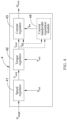
- FIG. 4 is a schematic block diagram of the controller 4 of the vehicle of the present disclosure. As shown in FIG. 4 , the controller 4 may include a speed regulator 41, a torque regulator 42, and a current regulator 43.
- the speed regulator 41 may receive the measured actual vehicle speed V act and a target vehicle speed V target , and generate a torque command T cmd of the AC electric machine 1 based on the actual vehicle speed V act and the target vehicle speed V target .
- the speed regulator 41 may include, for example, but is not limited to, a proportional integral (PI) regulator, and the speed regulator 41 calculates the torque command T cmd of the AC electric machine 1 according to the following formula (1).
- K p1 and K i1 are the proportion and the integral coefficient respectively.
- the torque regulator 42 may receive the torque command T cmd of the AC electric machine 1 from the speed regulator 41 and receive an actual torque T act .
- the actual torque T act of the AC electric machine 1 may be obtained according to the actual current I act of the stator of the AC electric machine 1.
- the actual current I act of the stator of the AC electric machine 1 may be measured first by a current measuring device (not shown), and then the actual current I act of the stator of the AC electric machine 1 is transmitted to the controller 4, and the controller 4 may calculate the actual torque T act based on the actual current I act of the stator of the AC electric machine 1.
- the torque regulator 42 may generate the current command I cmd of the stator of the AC electric machine 1 based on the torque command T cmd and the actual torque T act of the AC electric machine 1.
- the torque regulator 42 may include, but is not limited to, for example, a proportional integral (PI) regulator, and the torque regulator 42 calculates the current command T cmd of the stator of the AC electric machine 1 according to the following formula (2).
- K p2 and K i2 are the proportion and the integral coefficient respectively.
- the current regulator 43 may receive the current command I cmd from the stator of the AC electric machine 1 of the torque regulator 42 and receive the actual current I act of the stator and generate a voltage command U cmd of the stator of the AC electric machine 1 based on the current command I cmd of the stator of the AC electric machine 1 and the actual current I act of the stator.
- the current regulator 43 may include, but is not limited to, for example, a proportional integral (PI) regulator, and the current regulator 43 calculates the voltage command U cmd of the stator of the AC electric machine 1 according to the following formula (3).
- K p3 and K i3 are the proportion and the integral coefficient respectively.
- the controller 4 controls the healthy transistors Q 12 , Q 21 , Q 22 , Q 31 , and Q 32 in the inverter 3 based on the voltage command U cmd of the stator of the AC electric machine 1.
- the vehicle further includes a gate driver 5.
- the gate driver 5 is connected to all the transistors of the inverter 3 and is in communication with the controller 4, and the controller 4 can control the gate driver 5.
- the controller 4 sends the generated voltage command U cmd of the stator of the AC electric machine 1 to the gate driver 5.
- the gate driver 5 generates a pulse width modulation signal S PWM according to the voltage command U cmd of the stator of the AC electric machine 1, and then the pulse width modulation signal S PWM is sent as a gate driver signal to the healthy transistors Q 12 , Q 21 , Q 22 , Q 31 , and Q 32 in the inverter 3.
- the healthy transistors Q 12 , Q 21 , Q 22 , Q 31 , and Q 32 perform corresponding switch-on and switch-off operations according to the received pulse width modulation signal S PWM .
- the controller 4 of the present disclosure may further include a current bandwidth regulation module 44.
- the current bandwidth regulation module 44 may receive the actual current I act of the stator and the current command I cmd of the stator of the AC electric machine 1 of the torque regulator 42, and generate an adaptive current bandwidth I bw of the stator of the AC electric machine 1 according to the current command I cmd and the actual current I act of the stator of the AC electric machine 1.
- the current regulator 44 may receive the actual current I act of the stator and the current command I cmd of the stator of the AC electric machine 1 generated from the torque regulator 42, the current regulator 44 may further receive the adaptive current bandwidth I bw of the stator of the AC electric machine 1 generated by the current bandwidth regulation module 44, and then the current regulator 44 may generate the voltage command U cmd of the stator of the AC electric machine 1 based on the current command I cmd and the actual current I act of the stator of the AC electric machine 1, and the generated adaptive current bandwidth I bw .
- FIG. 5 shows a schematic diagram of the current bandwidth regulation module 44.
- the current bandwidth regulation module 44 may include a subtracter 441.
- the subtracter 441 receives the actual current I act of the stator of the AC electric machine 1 and the current command I cmd of the stator of the AC electric machine 1 generated from the torque regulator 42, and calculates a current difference ⁇ I between the current command I cmd and the actual current I act of the stator of the AC electric machine 1. This is shown in the following formula (4).
- ⁇ I I cmd ⁇ I act
- the current bandwidth regulation module 44 may reduce a current bandwidth of the stator of the AC electric machine 1 and use the reduced current bandwidth of the stator of the AC electric machine 1 as the generated adaptive current bandwidth I bw of the stator.
- a first current bandwidth I bw1 , a second current bandwidth I bw2 , a first current fluctuation value ⁇ I 1 , and a second current fluctuation value ⁇ I 2 are preset in the current bandwidth regulation module 44, the first current bandwidth I bw1 being greater than the second current bandwidth I bw2 , and the first current fluctuation value ⁇ I 1 being less than the second current fluctuation value ⁇ I 2 .
- a relationship curve 442 between the current bandwidth and the current fluctuation value is preset in the current bandwidth regulation module 44.
- the first current bandwidth I bw1 , the second current bandwidth I bw2 , the first current fluctuation value ⁇ I 1 , and the second current fluctuation value ⁇ I 2 may be determined according to the relationship curve 442 between the current bandwidth and the current fluctuation value.
- the current bandwidth regulation module 44 can determine the adaptive current bandwidth I bw of the stator of the AC electric machine 1 according to the calculated current difference ⁇ I with reference to the relationship curve 442 between the current bandwidth and the current fluctuation value.
- the adaptive current bandwidth I bw generated by the current bandwidth regulation module 44 is between the first current bandwidth I bw1 and the second current bandwidth I bw2 .
- I bw I bw 1 + I bw 2 ⁇ I bw 1 ⁇ I 2 ⁇ ⁇ I 1 ⁇ ⁇ I ⁇ ⁇ I 1 ⁇ I 1 ⁇ ⁇ I ⁇ ⁇ I 2
- the current regulator 43 may adjust the proportional and integral coefficient K p3 , and K i3 in the above formula (3) according to the adaptive current bandwidth I bw generated by the current bandwidth regulation module 44, and generate the corresponding voltage command U cmd of the stator according to the current difference ⁇ I between the current command I cmd and the actual current I act of the stator of the AC electric machine 1, so as to reduce torque ripple of the AC electric machine 1.
- the vehicle of the present disclosure can realize appropriate fault-tolerant control of the transistors in the inverter 3 according to a current actual speed V act of the vehicle. Therefore, the vehicle of the present disclosure can drive by its own driving force to a vehicle maintenance point without the help of a trailer, thereby reducing maintenance costs of the vehicle.
- the vehicle of the present disclosure can prevent a high current from being generated on the stator side of the AC electric machine 1 when a fault occurs in the inverter 3, reducing the current stress on the stator side. Furthermore, the vehicle of the present disclosure can reduce the torque ripple of the AC electric machine 1 when a fault occurs in the inverter 3.
- FIG. 6 shows a schematic flowchart of a control method of a vehicle according to a specific example of the present disclosure.
- the control method of a vehicle may include the following steps.
- a DC voltage U dc may be provided by a battery 2.
- step B2 the DC voltage U dc can be converted by the inverter 3 to an AC voltage to drive the AC electric machine 1, for example an IPM.
- step B3 traction drive force may be generated by the AC electric machine 1 to drive the vehicle.
- step B4 whether an open circuit fault occurs in any one of the transistors in the inverter 3 during the running of the vehicle is monitored.
- the process can proceed to step B5.
- step B5 the inverter 3 may be controlled by the controller 4 to maintain the vehicle to drive in a fault-tolerant mode. Specifically, in step B51, whether the measured actual vehicle speed V act is greater than a predetermined speed threshold V th is monitored. When the measured actual vehicle speed V act is greater than the predetermined speed threshold V th , the process can proceed to step B52. When the measured actual vehicle speed V act is less than the predetermined speed threshold V th , the process can proceed to step B53.
- step B52 when the measured vehicle speed V act is greater than the predetermined speed threshold V th , the controller 4 is used to remove a gate driver signal provided to all the transistors of the inverter 3.
- step B53 when the measured vehicle speed V act is less than the predetermined speed threshold V th , the controller 4 is used to maintain control of healthy transistors (Q 12 , Q 21 , Q 22 , Q 31 , and Q 32 ).
- controller 4 maintains control of healthy transistors in step B53 of FIG. 6 will be described in detail below with reference to FIG. 7 .
- a torque command T cmd of the AC electric machine 1 may be generated based on the measured vehicle speed V act and the target vehicle speed V target , for example, as shown in the above formula (1).
- step B532 the current command I cmd of the stator of the AC electric machine 1 may be generated based on the torque command T cmd of the AC electric machine 1 and the actual torque T act , as shown in the above formula (2).
- step B533 the voltage command U cmd of the stator of the AC electric machine 1 may be generated based on the current command I cmd of the stator of the AC electric machine 1 and the actual current I act of the stator, for example, as shown in the above formula (3). Then, the process can proceed to step B535.
- the step B53 of maintaining control of healthy transistors shown in FIG. 6 may further include the following step B534.
- step B534 the adaptive current bandwidth I bw of the stator of the AC electric machine 1 can be generated based on the current command I cmd of the stator of the AC electric machine 1 and the actual current I act .
- step B533 the voltage command U cmd of the stator of the AC electric machine 1 may further be generated based on the adaptive current bandwidth I bw of the stator generated in step B534.
- the generating the adaptive current bandwidth I bw in step B534 may include: when the current difference ⁇ I between the current command I cmd and the actual current I act of the stator of the AC electric machine 1 is greater than a preset current fluctuation value (for example, the first current fluctuation value ⁇ I 1 shown in FIG. 5 ), the current bandwidth of the stator of the AC electric machine 1 is reduced, and the reduced current bandwidth of the stator of the AC electric machine 1 is used as the generated adaptive current bandwidth I bw of the stator.
- the generation of the adaptive current bandwidth I bw in step B534 can be specifically referred to the above formula (5) to formula (7). Details are not described herein.
- step B535 healthy transistors in the inverter 3 can be controlled according to the voltage command U cmd of the stator of the AC electric machine 1.
- Step B535 may include the following steps.
- step B5351 the pulse width modulation signal S PWM may be generated based on the voltage command U cmd of the stator of the AC electric machine 1.
- the pulse width modulation signal S PWM may be sent to healthy transistors in the inverter 3, and the healthy transistors may perform corresponding switch-on and switch-off operations according to the received pulse width modulation signal S PWM .
- the controller 4 controls the gate driver 5 to provide a first gate driver signal to turn on the transistors of the inverter 3 to generate an AC voltage for driving the operation of the AC electric machine 1.
- the controller 4 controls, in response to the open circuit fault, the gate driver 5 to remove the first gate driver signal provided to all the transistors of the inverter 3 when the measured vehicle speed V act is greater than the predetermined speed threshold V th , and controls the gate driver 5 to provide a different second gate driver signal to turn on healthy transistors of the inverter 3 to generate a different second AC voltage that is sufficient to drive the AC electric machine 1 to move the vehicle when the measured vehicle speed V act is less than the predetermined speed threshold V th .
- control method of the present disclosure when an open circuit fault occurs in the inverter 3 of the vehicle, appropriate fault-tolerant control of the inverter 3 is performed, so as to prevent a high current from being generated on the stator side of the AC electric machine 1, reducing the current stress on the stator side. Furthermore, the control method of the vehicle of the present disclosure can further reduce the torque ripple of the AC electric machine 1.
- the present disclosure further provides a system.
- the system includes an AC electric machine 1 configured to generate driving force, a DC bus (for example, the battery 2 shown in the drawings of the present disclosure) configured to provide a DC voltage U dc , an inverter 3, and a controller 4.
- the inverter 3 is coupled with the battery 2 and configured to convert the DC voltage from the battery 2 to an AC voltage to drive the AC electric machine 1, and the inverter 3 includes a plurality of transistors.
- the controller 4 is configured to control the inverter 3 to maintain the AC electric machine 1 to operate in a fault-tolerant mode when an open circuit fault occurs in one of the transistors in the inverter 3 during operating of the AC electric machine 1.
- the controller 4 may use a rotational speed of the AC electric machine 1 instead of a vehicle speed of the vehicle as a determination criterion. Therefore, the controller 4 is configured to remove a gate driver signal provided to all the transistors of the inverter 3 if a rotational speed of the AC electric machine 1 is greater than a predetermined speed threshold, and maintain control of healthy transistors if the rotational speed of the AC electric machine 1 is less than the predetermined speed threshold.
- the controller may include a speed regulator 41, a torque regulator 42, and a current regulator 43.
- the speed regulator 41 is configured to generate a torque command T cmd of the AC electric machine 1 based on the rotational speed and a target rotational speed of the AC electric machine 1.
- the torque regulator 42 is configured to generate a current command I cmd of a stator of the AC electric machine 1 based on the torque command T cmd and an actual torque T act of the AC electric machine 1.
- the current regulator 43 is configured to generate a voltage command U cmd of the stator of the AC electric machine 1 based on the current command I cmd and an actual current I act of the stator of the AC electric machine 1.
- the controller 4 controls the healthy transistors of the inverter 3 based on the voltage command U cmd of the stator of the AC electric machine 1.
- the controller may further include a current bandwidth regulation module 44.
- the current bandwidth regulation module 44 generates an adaptive current bandwidth I bw of the stator of the AC electric machine 1 based on the current command I cmd and the actual current I act of the stator of the AC electric machine 1.
- the current regulator 43 is configured to generate the voltage command U cmd of the stator of the AC electric machine 1 based on the current command I cmd and the actual current I act of the stator of the AC electric machine 1, and the generated adaptive current bandwidth I bw .
- the generation of the adaptive current bandwidth I bw may refer to the foregoing description, and details are not described herein any more.
- the vehicle may include the above system, and the AC electric machine is an AC traction motor.
Landscapes
- Engineering & Computer Science (AREA)
- Power Engineering (AREA)
- Physics & Mathematics (AREA)
- General Physics & Mathematics (AREA)
- Mechanical Engineering (AREA)
- Sustainable Energy (AREA)
- Life Sciences & Earth Sciences (AREA)
- Sustainable Development (AREA)
- Transportation (AREA)
- Combustion & Propulsion (AREA)
- Chemical & Material Sciences (AREA)
- Electric Propulsion And Braking For Vehicles (AREA)
- Control Of Ac Motors In General (AREA)
- Inverter Devices (AREA)
- Control Of Eletrric Generators (AREA)
Claims (13)
- Fahrzeug, umfassend:eine elektrische Wechselstrommaschine (1), die so konfiguriert ist, dass sie eine Traktionsantriebskraft erzeugt;einen Gleichstrombus (2), der so konfiguriert ist, dass er eine Gleichspannung bereitstellt;einen Wechselrichter (3), der mit dem Gleichstrombus verbunden und so konfiguriert ist, dass er die Gleichspannung von dem Gleichstrombus in eine Wechselspannung umwandelt, um die elektrische Wechselstrommaschine anzutreiben, wobei der Wechselrichter eine Vielzahl von Transistoren umfasst; undeine Steuereinheit (4), die konfiguriert ist zum:Steuern des Wechselrichters (3), um das Laufen des Fahrzeugs in einem fehlertoleranten Modus aufrechtzuerhalten, wenn während des Laufens des Fahrzeugs in einem der Transistoren in dem Wechselrichter (3) eine Leitungsunterbrechung auftritt,dadurch gekennzeichnet, dass die Steuereinheit (4) ferner so konfiguriert ist, dass sie ein allen Transistoren des Wechselrichters (3) bereitgestelltes Gate-Treibersignal entfernt, wenn eine gemessene Fahrzeuggeschwindigkeit höher als ein vorgegebener Geschwindigkeitsschwellenwert ist; undAufrechterhalten der Steuerung der störungsfreien Transistoren, wenn die gemessene Fahrzeuggeschwindigkeit niedriger als der vorgegebene Geschwindigkeitsschwellenwert ist.
- Fahrzeug nach Anspruch 1, wobei die elektrische Wechselstrommaschine ein dreiphasiger Wechselstrommotor ist und der Wechselrichter drei Brückenzweige (31, 32, 33) umfasst, wobei jeder Brückenzweig zwei in Reihe geschaltete Transistoren und zwei Dioden aufweist und jeder Transistor antiparallel zu einer der beiden Dioden geschaltet ist.
- Fahrzeug nach Anspruch 1, wobei der vorgegebene Geschwindigkeitsschwellenwert mit der durch den Gleichstrombus (2) bereitgestellten Gleichspannung verknüpft ist.
- Fahrzeug nach Anspruch 1, wobei die Steuereinheit (4) umfasst:einen Geschwindigkeitsregler (41), der so konfiguriert ist, dass er auf der Grundlage der gemessenen Fahrzeuggeschwindigkeit und einer Soll-Fahrzeuggeschwindigkeit einen Drehmomentbefehl der elektrischen Wechselstrommaschine (1) erzeugt;einen Drehmomentregler (42), der so konfiguriert ist, dass er auf der Grundlage des Drehmomentbefehls und eines Ist-Drehmoments der elektrischen Wechselstrommaschine einen Strombefehl für einen Stator der elektrischen Wechselstrommaschine (1) erzeugt; undeinen Stromregler (43), der so konfiguriert ist, dass er auf der Grundlage des Strombefehls und eines Ist-Stroms des Stators der elektrischen Wechselstrommaschine (1) einen Spannungsbefehl für den Stator der elektrischen Wechselstrommaschine (1) erzeugt,wobei die Steuereinheit (4) so konfiguriert ist, dass sie die störungsfreien Transistoren des Wechselrichters auf der Grundlage des Spannungsbefehl des Stators der elektrischen Wechselstrommaschine steuert.
- Fahrzeug nach Anspruch 4, das ferner umfasst:
einen Gate-Treiber (5), der mit der Vielzahl von Transistoren des Wechselrichters (3) verbunden und so konfiguriert ist, dass er mit der Steuereinheit kommuniziert, wobei die Steuereinheit (4) so konfiguriert ist, dass sie den Gate-Treiber (5) steuert, um auf der Grundlage des Spannungsbefehl des Stators der elektrischen Wechselstrommaschine (1) ein Impulsbreitenmodulationssignal zu erzeugen, und das Impulsbreitenmodulationssignal wird als Gate-Treibersignal an die störungsfreien Transistoren des Wechselrichters (3) gesendet. - Fahrzeug nach Anspruch 4, wobei die Steuereinheit (4) ferner umfasst:ein Strombandbreitenregelungsmodul (44), das so konfiguriert ist, dass es auf der Grundlage des Strombefehls und des Ist-Stroms des Stators der elektrischen Wechselstrommaschine (1) eine adaptive Strombandbreite des Stators der elektrischen Wechselstrommaschine erzeugt,wobei der Stromregler (43) so konfiguriert ist, dass er auf der Grundlage des Strombefehls und des Ist-Stroms des Stators der elektrischen Wechselstrommaschine (1) und der erzeugten adaptiven Strombandbreite den Spannungsbefehl des Stators der elektrischen Wechselstrommaschine (1) erzeugt.
- Fahrzeug nach Anspruch 6, wobei das Strombandbreitenregelungsmodul (44) so konfiguriert ist, dass es eine Strombandbreite des Stators der elektrischen Wechselstrommaschine (1) reduziert, wenn eine Stromdifferenz zwischen dem Strombefehl und dem Ist-Strom des Stators der elektrischen Wechselstrommaschine (1) größer als ein voreingestellter Stromschwankungswert ist.
- Fahrzeug nach Anspruch 6, wobei eine erste Strombandbreite, eine zweite Strombandbreite, ein erster Stromschwankungswert und ein zweiter Stromschwankungswert in dem Strombandbreitenregelungsmodul (44) voreingestellt sind, wobei die erste Strombandbreite größer als die zweite Strombandbreite ist und der erste Stromschwankungswert kleiner als der zweite Stromschwankungswert ist, und wobeiwenn eine Stromdifferenz zwischen dem Strombefehl und dem Ist-Strom des Stators der elektrischen Wechselstrommaschine (1) kleiner als der erste Stromschwankungswert ist, die erzeugte adaptive Strombandbreite gleich der ersten Strombandbreite ist;wenn die Stromdifferenz zwischen dem Strombefehl und dem Ist-Strom des Stators der elektrischen Wechselstrommaschine (1) größer als der zweite Stromschwankungswert ist, die erzeugte adaptive Strombandbreite gleich der zweiten Strombandbreite ist; undwenn die Stromdifferenz zwischen dem Strombefehl und dem Ist-Strom des Stators der elektrischen Wechselstrommaschine (1) zwischen dem ersten und dem zweiten Stromschwankungswert liegt, die erzeugte adaptive Strombandbreite zwischen der ersten und der zweiten Strombandbreite liegt.
- Steuerungsverfahren für ein Fahrzeug, wobei das Steuerungsverfahren umfasst:(B1) Bereitstellen einer Gleichspannung;(B2) Umwandeln, durch einen Wechselrichter (3), der eine Vielzahl von Transistoren aufweist, der Gleichspannung in eine Wechselspannung, um eine elektrische Wechselstrommaschine (1) anzutreiben;(B3) Erzeugen einer Traktionsantriebskraft durch die elektrische Wechselstrommaschine (1), um das Fahrzeug anzutreiben; und(B5) Steuern des Wechselrichters (3), um das Laufen des Fahrzeugs in einem fehlertoleranten Modus aufrechtzuerhalten, wenn während des Laufens des Fahrzeugs in einem der Transistoren in dem Wechselrichter eine Leitungsunterbrechung auftritt,dadurch gekennzeichnet, dass das Steuern des Wechselrichters umfasst:(B52) Entfernen eines allen Transistoren des Wechselrichters (3) bereitgestellten Gate-Treibersignals, wenn eine gemessene Fahrzeuggeschwindigkeit höher als ein vorgegebener Geschwindigkeitsschwellenwert ist; und(B53) Aufrechterhalten der Steuerung der störungsfreien Transistoren, wenn die gemessene Fahrzeuggeschwindigkeit niedriger als der vorgegebene Geschwindigkeitsschwellenwert ist.
- Steuerungsverfahren nach Anspruch 9, wobei das Aufrechterhalten der Steuerung der störungsfreien Transistoren umfasst:(B531) Erzeugen eines Drehmomentbefehls der elektrischen Wechselstrommaschine (1) auf der Grundlage der gemessenen Fahrzeuggeschwindigkeit und einer Soll-Fahrzeuggeschwindigkeit;(B532) Erzeugen eines Strombefehls für einen Stator der elektrischen Wechselstrommaschine (1) auf der Grundlage des Drehmomentbefehls und eines Ist-Drehmoments der elektrischen Wechselstrommaschine (1);(B533) Erzeugen eines Spannungsbefehls für den Stator der elektrischen Wechselstrommaschine (1) auf der Grundlage des Strombefehls und eines Ist-Stroms des Stators der elektrischen Wechselstrommaschine (1); und(B535) Steuern der störungsfreien Transistoren des Wechselrichters auf der Grundlage des Spannungsbefehls des Stators der elektrischen Wechselstrommaschine (1).
- Steuerungsverfahren nach Anspruch 10, wobei das Aufrechterhalten der Steuerung der störungsfreien Transistoren ferner umfasst:
(B534) Erzeugen einer adaptiven Strombandbreite des Stators der elektrischen Wechselstrommaschine (1) auf der Grundlage des Strombefehls und des Ist-Stroms des Stators der elektrischen Wechselstrommaschine, wobei der Spannungsbefehl des Stators der elektrischen Wechselstrommaschine (1) ferner auf der Grundlage der erzeugten adaptiven Strombandbreite erzeugt wird. - Steuerungsverfahren nach Anspruch 11, wobei das Erzeugen der adaptiven Strombandbreite umfasst:
Reduzieren einer Strombandbreite des Stators der elektrischen Wechselstrommaschine (1), wenn eine Stromdifferenz zwischen dem Strombefehl und dem Ist-Strom des Stators der elektrischen Wechselstrommaschine (1) größer als ein voreingestellter Stromschwankungswert ist. - Steuerungsverfahren nach Anspruch 9, wobei:das Umwandeln der Gleichspannung in Wechselspannung zum Antreiben der elektrischen Wechselstrommaschine (1) das Steuern eines Gate-Treibers (5) durch eine Steuereinheit (4) umfasst, um ein erstes Gate-Treibersignal bereitzustellen, um die Transistoren des Wechselrichters einzuschalten (3), um die Wechselspannung zu erzeugen; unddas Steuern des Wechselrichters (3), um das Laufen des Fahrzeugs in einem fehlertoleranten Modus aufrechtzuerhalten, umfasst, den Gate-Treiber (5) durch die Steuereinheit (4) als Reaktion auf den Unterbrechungsfehler zu steuern, um das allen Transistoren des Wechselrichters (3) bereitgestellte erste Gate-Treibersignal zu entfernen, wenn eine gemessene Fahrzeuggeschwindigkeit höher als der vorgegebene Geschwindigkeitsschwellenwert ist; und den Gate-Treiber zu steuern, um ein anderes zweites Gate-Treibersignal bereitzustellen, um störungsfreie Transistoren des Wechselrichters einzuschalten, um eine andere zweite Wechselspannung zu erzeugen, die ausreicht, um die elektrische Wechselstrommaschine (1) anzutreiben, um das Fahrzeug zu bewegen, wenn die gemessene Fahrzeuggeschwindigkeit niedriger als der vorgegebene Geschwindigkeitsschwellenwert ist.
Applications Claiming Priority (2)
| Application Number | Priority Date | Filing Date | Title |
|---|---|---|---|
| CN201710260910.7A CN108736791B (zh) | 2017-04-20 | 2017-04-20 | 车辆及其控制方法及系统 |
| PCT/US2018/027849 WO2018195003A1 (en) | 2017-04-20 | 2018-04-17 | Vehicle and control method thereof and system |
Publications (3)
| Publication Number | Publication Date |
|---|---|
| EP3612847A1 EP3612847A1 (de) | 2020-02-26 |
| EP3612847A4 EP3612847A4 (de) | 2021-01-27 |
| EP3612847B1 true EP3612847B1 (de) | 2023-08-02 |
Family
ID=63856866
Family Applications (1)
| Application Number | Title | Priority Date | Filing Date |
|---|---|---|---|
| EP18787396.3A Active EP3612847B1 (de) | 2017-04-20 | 2018-04-17 | Fahrzeug und steuerungsverfahren dafür und system |
Country Status (5)
| Country | Link |
|---|---|
| US (1) | US11201567B2 (de) |
| EP (1) | EP3612847B1 (de) |
| CN (1) | CN108736791B (de) |
| ES (1) | ES2958657T3 (de) |
| WO (1) | WO2018195003A1 (de) |
Families Citing this family (10)
| Publication number | Priority date | Publication date | Assignee | Title |
|---|---|---|---|---|
| CN108736791B (zh) * | 2017-04-20 | 2022-03-29 | 通用电气公司 | 车辆及其控制方法及系统 |
| JP7183797B2 (ja) * | 2019-01-08 | 2022-12-06 | 株式会社デンソー | 電力変換装置 |
| WO2021034813A1 (en) | 2019-08-22 | 2021-02-25 | Cummins Inc. | Flexible control for a six-phase machine |
| US10992147B2 (en) * | 2019-09-25 | 2021-04-27 | GM Global Technology Operations LLC | Diagnostic method for electric propulsion system with reconfigurable battery system |
| CN111038261B (zh) * | 2019-12-12 | 2023-05-26 | 联合汽车电子有限公司 | 拖车保护方法 |
| CN111948573B (zh) * | 2020-07-13 | 2021-04-20 | 华中科技大学 | 一种级联多电平逆变器开路故障识别定位方法和系统 |
| CN111740676B (zh) * | 2020-08-20 | 2021-06-15 | 南京众科汇电气科技有限公司 | 电驱动系统功率管开路故障容错控制方法 |
| DE102021116963B4 (de) * | 2021-07-01 | 2023-06-15 | Schaeffler Technologies AG & Co. KG | Verfahren zur Drehmomentschätzung einer elektrischen Maschine, Steuereinheit zur Ausführung dieses Verfahrens und elektrischer Traktionsantrieb mit derartiger Steuereinheit |
| CN114679057B (zh) * | 2022-04-02 | 2026-04-24 | 苏州汇川联合动力系统股份有限公司 | 直流变换器控制方法 |
| CN116572760B (zh) * | 2023-06-25 | 2024-12-31 | 安徽锐能科技有限公司 | 一种前级容错时电动汽车驱动电机的控制方法及系统 |
Family Cites Families (24)
| Publication number | Priority date | Publication date | Assignee | Title |
|---|---|---|---|---|
| US3641539A (en) * | 1968-12-23 | 1972-02-08 | James Barber | Remote monitoring and control system |
| US4310866A (en) * | 1979-09-28 | 1982-01-12 | Borg-Warner Corporation | Shootthrough fault protection system for bipolar transistors in a voltage source transistor inverter |
| GB2073434B (en) * | 1980-03-28 | 1984-03-14 | Plessey Co Ltd | Remote switch monitoring circuit for mining |
| JP2009500994A (ja) * | 2005-06-30 | 2009-01-08 | シーメンス ヴィディーオー オートモーティヴ コーポレイション | 電気駆動機構に好適な制御方法、制御装置及び制御部材 |
| US7279862B1 (en) | 2006-08-04 | 2007-10-09 | Gm Global Technology Operations, Inc. | Fault handling of inverter driven PM motor drives |
| US7652858B2 (en) * | 2007-06-06 | 2010-01-26 | Gm Global Technology Operations, Inc. | Protection for permanent magnet motor control circuits |
| JP4609474B2 (ja) * | 2007-10-10 | 2011-01-12 | 株式会社デンソー | 回転電機装置 |
| US8174224B2 (en) | 2009-05-22 | 2012-05-08 | GM Global Technology Operations LLC | Torque production in an electric motor in response to current sensor error |
| US9071188B2 (en) | 2009-09-04 | 2015-06-30 | Black & Decker Inc. | Protective redundant subsystem for power tools |
| DE102009045351A1 (de) * | 2009-10-06 | 2011-04-14 | Robert Bosch Gmbh | Verfahren zum Betreiben eines Antriebsaggregats sowie Antriebsaggregat |
| FR2954618B1 (fr) | 2009-12-22 | 2012-12-28 | Astrium Sas | Onduleur reconfigurable, a tolerance de pannes, pour l'alimentation d'un moteur triphase synchrone a aimants permanents, et ensemble desdits onduleur et moteur |
| JP4817084B2 (ja) * | 2010-03-30 | 2011-11-16 | 株式会社安川電機 | モータ駆動システム及びモータ制御装置 |
| US8606447B2 (en) * | 2011-05-23 | 2013-12-10 | GM Global Technology Operations LLC | Method and apparatus to operate a powertrain system including an electric machine having a disconnected high-voltage battery |
| DE102011081173A1 (de) * | 2011-08-18 | 2013-02-21 | Robert Bosch Gmbh | Betriebszustandsschaltung für Wechselrichter und Verfahren zum Einstellen von Betriebszuständen eines Wechselrichters |
| KR101283892B1 (ko) | 2011-12-07 | 2013-07-08 | 기아자동차주식회사 | 친환경 차량에서 dc-dc컨버터 제어장치 및 방법 |
| CN102998588B (zh) * | 2012-12-14 | 2014-11-19 | 山东理工大学 | 一种无刷直流电机逆变器常见断路故障诊断方法 |
| CN103869208B (zh) * | 2014-03-07 | 2016-07-27 | 电子科技大学 | 相冗余容错结构的三相逆变器开路故障检测方法 |
| CN103986310B (zh) | 2014-05-30 | 2017-07-14 | 台达电子企业管理(上海)有限公司 | 变流器电路及其开路检测方法 |
| US9645185B2 (en) * | 2015-03-05 | 2017-05-09 | Ford Global Technologies, Llc | AC traction motor fault detection using DC bus leakage hardware |
| CN104779892B (zh) * | 2015-04-02 | 2017-09-26 | 福州大学 | 基于y‑△变换扩大交流电动机恒转矩变频调速范围的系统与方法 |
| US10355581B2 (en) * | 2015-09-22 | 2019-07-16 | Schlumberger Technology Corporation | Fault tolerant inverter or controlled rectifier system |
| CN108780993B (zh) * | 2015-11-13 | 2020-01-10 | 马凯特大学 | 一种用于多电平t型变换器的容错拓扑结构 |
| CN108736791B (zh) * | 2017-04-20 | 2022-03-29 | 通用电气公司 | 车辆及其控制方法及系统 |
| CN109933881A (zh) * | 2019-03-06 | 2019-06-25 | 武汉大学 | 一种基于优化深度信念网络的电力电子电路故障诊断方法 |
-
2017
- 2017-04-20 CN CN201710260910.7A patent/CN108736791B/zh active Active
-
2018
- 2018-04-17 ES ES18787396T patent/ES2958657T3/es active Active
- 2018-04-17 US US16/605,842 patent/US11201567B2/en not_active Expired - Fee Related
- 2018-04-17 WO PCT/US2018/027849 patent/WO2018195003A1/en not_active Ceased
- 2018-04-17 EP EP18787396.3A patent/EP3612847B1/de active Active
Also Published As
| Publication number | Publication date |
|---|---|
| ES2958657T3 (es) | 2024-02-13 |
| WO2018195003A1 (en) | 2018-10-25 |
| US11201567B2 (en) | 2021-12-14 |
| EP3612847A1 (de) | 2020-02-26 |
| EP3612847A4 (de) | 2021-01-27 |
| CN108736791A (zh) | 2018-11-02 |
| CN108736791B (zh) | 2022-03-29 |
| US20200076326A1 (en) | 2020-03-05 |
Similar Documents
| Publication | Publication Date | Title |
|---|---|---|
| US11201567B2 (en) | Vehicle and control method thereof and system | |
| US11299062B2 (en) | Motor drive device | |
| US8305018B2 (en) | Power supply system and electric powered vehicle using the same | |
| JP6296169B2 (ja) | インバータ制御装置及び車両用制御装置 | |
| CN111108681B (zh) | 逆变器控制装置 | |
| CN111319467A (zh) | 车辆的电源系统 | |
| US8045301B2 (en) | Motor drive device | |
| US7557543B2 (en) | Method and system for discharging a capacitive element | |
| EP3213958B1 (de) | Gleichstrombusspannungssteuerung | |
| US9236736B2 (en) | Power supply system and method for controlling the same | |
| CN112693314B (zh) | 车辆的电源系统 | |
| CN107404278B (zh) | 用于电驱动系统的故障保护 | |
| KR102829322B1 (ko) | 차량 내의 인버터를 과전압으로부터 보호하는 시스템 및 방법 | |
| KR102829354B1 (ko) | 차량 내의 인버터를 과전압으로부터 보호하는 시스템 및 방법 | |
| JP2012110200A (ja) | 車両およびその制御方法 | |
| JP2020058176A (ja) | モータ駆動システム | |
| JP5191351B2 (ja) | 電力変換装置 | |
| EP3805038A1 (de) | Wechselrichtersteuerungsverfahren und wechselrichtersteuersystem | |
| JP4905204B2 (ja) | 負荷駆動装置 | |
| JPWO2020137567A1 (ja) | モータ制御装置 | |
| JP2009225500A (ja) | モータ駆動装置およびその制御方法 | |
| JP2008141868A (ja) | 電動機システム | |
| JP4590960B2 (ja) | 電動機駆動装置 | |
| CN117227500B (zh) | 车辆制动方法、装置、设备、存储介质以及车辆 | |
| JP2011259523A (ja) | モータ制御装置 |
Legal Events
| Date | Code | Title | Description |
|---|---|---|---|
| STAA | Information on the status of an ep patent application or granted ep patent |
Free format text: STATUS: THE INTERNATIONAL PUBLICATION HAS BEEN MADE |
|
| PUAI | Public reference made under article 153(3) epc to a published international application that has entered the european phase |
Free format text: ORIGINAL CODE: 0009012 |
|
| STAA | Information on the status of an ep patent application or granted ep patent |
Free format text: STATUS: REQUEST FOR EXAMINATION WAS MADE |
|
| 17P | Request for examination filed |
Effective date: 20191112 |
|
| AK | Designated contracting states |
Kind code of ref document: A1 Designated state(s): AL AT BE BG CH CY CZ DE DK EE ES FI FR GB GR HR HU IE IS IT LI LT LU LV MC MK MT NL NO PL PT RO RS SE SI SK SM TR |
|
| AX | Request for extension of the european patent |
Extension state: BA ME |
|
| DAV | Request for validation of the european patent (deleted) | ||
| DAX | Request for extension of the european patent (deleted) | ||
| REG | Reference to a national code |
Ref country code: DE Ref legal event code: R079 Free format text: PREVIOUS MAIN CLASS: G01R0031020000 Ipc: G01R0031000000 Ref country code: DE Ref legal event code: R079 Ref document number: 602018054615 Country of ref document: DE Free format text: PREVIOUS MAIN CLASS: G01R0031020000 Ipc: G01R0031000000 |
|
| A4 | Supplementary search report drawn up and despatched |
Effective date: 20210114 |
|
| RIC1 | Information provided on ipc code assigned before grant |
Ipc: G01R 31/34 20200101ALI20201223BHEP Ipc: B60L 50/51 20190101ALI20201223BHEP Ipc: H02M 7/53862 20070101ALI20201223BHEP Ipc: H02M 7/5387 20070101ALI20201223BHEP Ipc: H02P 29/024 20160101ALI20201223BHEP Ipc: H02P 29/10 20160101ALI20201223BHEP Ipc: B60L 3/00 20190101ALI20201223BHEP Ipc: H02M 1/32 20070101ALI20201223BHEP Ipc: H02P 27/06 20060101ALI20201223BHEP Ipc: G01R 31/36 20200101ALI20201223BHEP Ipc: H02P 29/032 20160101ALI20201223BHEP Ipc: G01R 31/00 20060101AFI20201223BHEP Ipc: H02P 27/04 20160101ALI20201223BHEP |
|
| GRAP | Despatch of communication of intention to grant a patent |
Free format text: ORIGINAL CODE: EPIDOSNIGR1 |
|
| STAA | Information on the status of an ep patent application or granted ep patent |
Free format text: STATUS: GRANT OF PATENT IS INTENDED |
|
| INTG | Intention to grant announced |
Effective date: 20230314 |
|
| GRAS | Grant fee paid |
Free format text: ORIGINAL CODE: EPIDOSNIGR3 |
|
| GRAA | (expected) grant |
Free format text: ORIGINAL CODE: 0009210 |
|
| STAA | Information on the status of an ep patent application or granted ep patent |
Free format text: STATUS: THE PATENT HAS BEEN GRANTED |
|
| AK | Designated contracting states |
Kind code of ref document: B1 Designated state(s): AL AT BE BG CH CY CZ DE DK EE ES FI FR GB GR HR HU IE IS IT LI LT LU LV MC MK MT NL NO PL PT RO RS SE SI SK SM TR |
|
| REG | Reference to a national code |
Ref country code: GB Ref legal event code: FG4D |
|
| REG | Reference to a national code |
Ref country code: CH Ref legal event code: EP |
|
| REG | Reference to a national code |
Ref country code: DE Ref legal event code: R096 Ref document number: 602018054615 Country of ref document: DE |
|
| REG | Reference to a national code |
Ref country code: IE Ref legal event code: FG4D |
|
| REG | Reference to a national code |
Ref country code: LT Ref legal event code: MG9D |
|
| REG | Reference to a national code |
Ref country code: NL Ref legal event code: MP Effective date: 20230802 |
|
| REG | Reference to a national code |
Ref country code: AT Ref legal event code: MK05 Ref document number: 1595384 Country of ref document: AT Kind code of ref document: T Effective date: 20230802 |
|
| PG25 | Lapsed in a contracting state [announced via postgrant information from national office to epo] |
Ref country code: GR Free format text: LAPSE BECAUSE OF FAILURE TO SUBMIT A TRANSLATION OF THE DESCRIPTION OR TO PAY THE FEE WITHIN THE PRESCRIBED TIME-LIMIT Effective date: 20231103 |
|
| PG25 | Lapsed in a contracting state [announced via postgrant information from national office to epo] |
Ref country code: IS Free format text: LAPSE BECAUSE OF FAILURE TO SUBMIT A TRANSLATION OF THE DESCRIPTION OR TO PAY THE FEE WITHIN THE PRESCRIBED TIME-LIMIT Effective date: 20231202 |
|
| PG25 | Lapsed in a contracting state [announced via postgrant information from national office to epo] |
Ref country code: SE Free format text: LAPSE BECAUSE OF FAILURE TO SUBMIT A TRANSLATION OF THE DESCRIPTION OR TO PAY THE FEE WITHIN THE PRESCRIBED TIME-LIMIT Effective date: 20230802 Ref country code: RS Free format text: LAPSE BECAUSE OF FAILURE TO SUBMIT A TRANSLATION OF THE DESCRIPTION OR TO PAY THE FEE WITHIN THE PRESCRIBED TIME-LIMIT Effective date: 20230802 Ref country code: PT Free format text: LAPSE BECAUSE OF FAILURE TO SUBMIT A TRANSLATION OF THE DESCRIPTION OR TO PAY THE FEE WITHIN THE PRESCRIBED TIME-LIMIT Effective date: 20231204 Ref country code: NO Free format text: LAPSE BECAUSE OF FAILURE TO SUBMIT A TRANSLATION OF THE DESCRIPTION OR TO PAY THE FEE WITHIN THE PRESCRIBED TIME-LIMIT Effective date: 20231102 Ref country code: NL Free format text: LAPSE BECAUSE OF FAILURE TO SUBMIT A TRANSLATION OF THE DESCRIPTION OR TO PAY THE FEE WITHIN THE PRESCRIBED TIME-LIMIT Effective date: 20230802 Ref country code: LV Free format text: LAPSE BECAUSE OF FAILURE TO SUBMIT A TRANSLATION OF THE DESCRIPTION OR TO PAY THE FEE WITHIN THE PRESCRIBED TIME-LIMIT Effective date: 20230802 Ref country code: LT Free format text: LAPSE BECAUSE OF FAILURE TO SUBMIT A TRANSLATION OF THE DESCRIPTION OR TO PAY THE FEE WITHIN THE PRESCRIBED TIME-LIMIT Effective date: 20230802 Ref country code: IS Free format text: LAPSE BECAUSE OF FAILURE TO SUBMIT A TRANSLATION OF THE DESCRIPTION OR TO PAY THE FEE WITHIN THE PRESCRIBED TIME-LIMIT Effective date: 20231202 Ref country code: HR Free format text: LAPSE BECAUSE OF FAILURE TO SUBMIT A TRANSLATION OF THE DESCRIPTION OR TO PAY THE FEE WITHIN THE PRESCRIBED TIME-LIMIT Effective date: 20230802 Ref country code: GR Free format text: LAPSE BECAUSE OF FAILURE TO SUBMIT A TRANSLATION OF THE DESCRIPTION OR TO PAY THE FEE WITHIN THE PRESCRIBED TIME-LIMIT Effective date: 20231103 Ref country code: FI Free format text: LAPSE BECAUSE OF FAILURE TO SUBMIT A TRANSLATION OF THE DESCRIPTION OR TO PAY THE FEE WITHIN THE PRESCRIBED TIME-LIMIT Effective date: 20230802 Ref country code: AT Free format text: LAPSE BECAUSE OF FAILURE TO SUBMIT A TRANSLATION OF THE DESCRIPTION OR TO PAY THE FEE WITHIN THE PRESCRIBED TIME-LIMIT Effective date: 20230802 |
|
| REG | Reference to a national code |
Ref country code: ES Ref legal event code: FG2A Ref document number: 2958657 Country of ref document: ES Kind code of ref document: T3 Effective date: 20240213 |
|
| PG25 | Lapsed in a contracting state [announced via postgrant information from national office to epo] |
Ref country code: PL Free format text: LAPSE BECAUSE OF FAILURE TO SUBMIT A TRANSLATION OF THE DESCRIPTION OR TO PAY THE FEE WITHIN THE PRESCRIBED TIME-LIMIT Effective date: 20230802 |
|
| PG25 | Lapsed in a contracting state [announced via postgrant information from national office to epo] |
Ref country code: SM Free format text: LAPSE BECAUSE OF FAILURE TO SUBMIT A TRANSLATION OF THE DESCRIPTION OR TO PAY THE FEE WITHIN THE PRESCRIBED TIME-LIMIT Effective date: 20230802 Ref country code: RO Free format text: LAPSE BECAUSE OF FAILURE TO SUBMIT A TRANSLATION OF THE DESCRIPTION OR TO PAY THE FEE WITHIN THE PRESCRIBED TIME-LIMIT Effective date: 20230802 Ref country code: EE Free format text: LAPSE BECAUSE OF FAILURE TO SUBMIT A TRANSLATION OF THE DESCRIPTION OR TO PAY THE FEE WITHIN THE PRESCRIBED TIME-LIMIT Effective date: 20230802 Ref country code: DK Free format text: LAPSE BECAUSE OF FAILURE TO SUBMIT A TRANSLATION OF THE DESCRIPTION OR TO PAY THE FEE WITHIN THE PRESCRIBED TIME-LIMIT Effective date: 20230802 Ref country code: CZ Free format text: LAPSE BECAUSE OF FAILURE TO SUBMIT A TRANSLATION OF THE DESCRIPTION OR TO PAY THE FEE WITHIN THE PRESCRIBED TIME-LIMIT Effective date: 20230802 Ref country code: SK Free format text: LAPSE BECAUSE OF FAILURE TO SUBMIT A TRANSLATION OF THE DESCRIPTION OR TO PAY THE FEE WITHIN THE PRESCRIBED TIME-LIMIT Effective date: 20230802 |
|
| REG | Reference to a national code |
Ref country code: DE Ref legal event code: R097 Ref document number: 602018054615 Country of ref document: DE |
|
| PLBE | No opposition filed within time limit |
Free format text: ORIGINAL CODE: 0009261 |
|
| STAA | Information on the status of an ep patent application or granted ep patent |
Free format text: STATUS: NO OPPOSITION FILED WITHIN TIME LIMIT |
|
| 26N | No opposition filed |
Effective date: 20240503 |
|
| PG25 | Lapsed in a contracting state [announced via postgrant information from national office to epo] |
Ref country code: SI Free format text: LAPSE BECAUSE OF FAILURE TO SUBMIT A TRANSLATION OF THE DESCRIPTION OR TO PAY THE FEE WITHIN THE PRESCRIBED TIME-LIMIT Effective date: 20230802 |
|
| PG25 | Lapsed in a contracting state [announced via postgrant information from national office to epo] |
Ref country code: BG Free format text: LAPSE BECAUSE OF FAILURE TO SUBMIT A TRANSLATION OF THE DESCRIPTION OR TO PAY THE FEE WITHIN THE PRESCRIBED TIME-LIMIT Effective date: 20230802 |
|
| PG25 | Lapsed in a contracting state [announced via postgrant information from national office to epo] |
Ref country code: MC Free format text: LAPSE BECAUSE OF FAILURE TO SUBMIT A TRANSLATION OF THE DESCRIPTION OR TO PAY THE FEE WITHIN THE PRESCRIBED TIME-LIMIT Effective date: 20230802 |
|
| PG25 | Lapsed in a contracting state [announced via postgrant information from national office to epo] |
Ref country code: MC Free format text: LAPSE BECAUSE OF FAILURE TO SUBMIT A TRANSLATION OF THE DESCRIPTION OR TO PAY THE FEE WITHIN THE PRESCRIBED TIME-LIMIT Effective date: 20230802 Ref country code: BG Free format text: LAPSE BECAUSE OF FAILURE TO SUBMIT A TRANSLATION OF THE DESCRIPTION OR TO PAY THE FEE WITHIN THE PRESCRIBED TIME-LIMIT Effective date: 20230802 |
|
| REG | Reference to a national code |
Ref country code: CH Ref legal event code: PL |
|
| PG25 | Lapsed in a contracting state [announced via postgrant information from national office to epo] |
Ref country code: LU Free format text: LAPSE BECAUSE OF NON-PAYMENT OF DUE FEES Effective date: 20240417 |
|
| REG | Reference to a national code |
Ref country code: BE Ref legal event code: MM Effective date: 20240430 |
|
| PG25 | Lapsed in a contracting state [announced via postgrant information from national office to epo] |
Ref country code: LU Free format text: LAPSE BECAUSE OF NON-PAYMENT OF DUE FEES Effective date: 20240417 |
|
| PG25 | Lapsed in a contracting state [announced via postgrant information from national office to epo] |
Ref country code: BE Free format text: LAPSE BECAUSE OF NON-PAYMENT OF DUE FEES Effective date: 20240430 |
|
| PG25 | Lapsed in a contracting state [announced via postgrant information from national office to epo] |
Ref country code: BE Free format text: LAPSE BECAUSE OF NON-PAYMENT OF DUE FEES Effective date: 20240430 Ref country code: CH Free format text: LAPSE BECAUSE OF NON-PAYMENT OF DUE FEES Effective date: 20240430 |
|
| PG25 | Lapsed in a contracting state [announced via postgrant information from national office to epo] |
Ref country code: IE Free format text: LAPSE BECAUSE OF NON-PAYMENT OF DUE FEES Effective date: 20240417 |
|
| PGFP | Annual fee paid to national office [announced via postgrant information from national office to epo] |
Ref country code: DE Payment date: 20250429 Year of fee payment: 8 |
|
| PGFP | Annual fee paid to national office [announced via postgrant information from national office to epo] |
Ref country code: ES Payment date: 20250505 Year of fee payment: 8 Ref country code: GB Payment date: 20250428 Year of fee payment: 8 |
|
| PGFP | Annual fee paid to national office [announced via postgrant information from national office to epo] |
Ref country code: IT Payment date: 20250422 Year of fee payment: 8 |
|
| PGFP | Annual fee paid to national office [announced via postgrant information from national office to epo] |
Ref country code: FR Payment date: 20250425 Year of fee payment: 8 |
|
| PG25 | Lapsed in a contracting state [announced via postgrant information from national office to epo] |
Ref country code: CY Free format text: LAPSE BECAUSE OF FAILURE TO SUBMIT A TRANSLATION OF THE DESCRIPTION OR TO PAY THE FEE WITHIN THE PRESCRIBED TIME-LIMIT; INVALID AB INITIO Effective date: 20180417 |
|
| PG25 | Lapsed in a contracting state [announced via postgrant information from national office to epo] |
Ref country code: HU Free format text: LAPSE BECAUSE OF FAILURE TO SUBMIT A TRANSLATION OF THE DESCRIPTION OR TO PAY THE FEE WITHIN THE PRESCRIBED TIME-LIMIT; INVALID AB INITIO Effective date: 20180417 |