EP3614089A1 - Chambre à vapeur fondée sur tube caloporteur en boucle plate - Google Patents
Chambre à vapeur fondée sur tube caloporteur en boucle plate Download PDFInfo
- Publication number
- EP3614089A1 EP3614089A1 EP17906083.5A EP17906083A EP3614089A1 EP 3614089 A1 EP3614089 A1 EP 3614089A1 EP 17906083 A EP17906083 A EP 17906083A EP 3614089 A1 EP3614089 A1 EP 3614089A1
- Authority
- EP
- European Patent Office
- Prior art keywords
- heat
- vapor chamber
- flat plate
- evaporator
- attached
- Prior art date
- Legal status (The legal status is an assumption and is not a legal conclusion. Google has not performed a legal analysis and makes no representation as to the accuracy of the status listed.)
- Granted
Links
Images

Classifications
-
- F—MECHANICAL ENGINEERING; LIGHTING; HEATING; WEAPONS; BLASTING
- F28—HEAT EXCHANGE IN GENERAL
- F28D—HEAT-EXCHANGE APPARATUS, NOT PROVIDED FOR IN ANOTHER SUBCLASS, IN WHICH THE HEAT-EXCHANGE MEDIA DO NOT COME INTO DIRECT CONTACT
- F28D15/00—Heat-exchange apparatus with the intermediate heat-transfer medium in closed tubes passing into or through the conduit walls ; Heat-exchange apparatus employing intermediate heat-transfer medium or bodies
- F28D15/02—Heat-exchange apparatus with the intermediate heat-transfer medium in closed tubes passing into or through the conduit walls ; Heat-exchange apparatus employing intermediate heat-transfer medium or bodies in which the medium condenses and evaporates, e.g. heat pipes
- F28D15/0233—Heat-exchange apparatus with the intermediate heat-transfer medium in closed tubes passing into or through the conduit walls ; Heat-exchange apparatus employing intermediate heat-transfer medium or bodies in which the medium condenses and evaporates, e.g. heat pipes the conduits having a particular shape, e.g. non-circular cross-section, annular
-
- F—MECHANICAL ENGINEERING; LIGHTING; HEATING; WEAPONS; BLASTING
- F28—HEAT EXCHANGE IN GENERAL
- F28D—HEAT-EXCHANGE APPARATUS, NOT PROVIDED FOR IN ANOTHER SUBCLASS, IN WHICH THE HEAT-EXCHANGE MEDIA DO NOT COME INTO DIRECT CONTACT
- F28D15/00—Heat-exchange apparatus with the intermediate heat-transfer medium in closed tubes passing into or through the conduit walls ; Heat-exchange apparatus employing intermediate heat-transfer medium or bodies
- F28D15/02—Heat-exchange apparatus with the intermediate heat-transfer medium in closed tubes passing into or through the conduit walls ; Heat-exchange apparatus employing intermediate heat-transfer medium or bodies in which the medium condenses and evaporates, e.g. heat pipes
- F28D15/04—Heat-exchange apparatus with the intermediate heat-transfer medium in closed tubes passing into or through the conduit walls ; Heat-exchange apparatus employing intermediate heat-transfer medium or bodies in which the medium condenses and evaporates, e.g. heat pipes with tubes having a capillary structure
- F28D15/043—Heat-exchange apparatus with the intermediate heat-transfer medium in closed tubes passing into or through the conduit walls ; Heat-exchange apparatus employing intermediate heat-transfer medium or bodies in which the medium condenses and evaporates, e.g. heat pipes with tubes having a capillary structure forming loops, e.g. capillary pumped loops
-
- F—MECHANICAL ENGINEERING; LIGHTING; HEATING; WEAPONS; BLASTING
- F28—HEAT EXCHANGE IN GENERAL
- F28D—HEAT-EXCHANGE APPARATUS, NOT PROVIDED FOR IN ANOTHER SUBCLASS, IN WHICH THE HEAT-EXCHANGE MEDIA DO NOT COME INTO DIRECT CONTACT
- F28D15/00—Heat-exchange apparatus with the intermediate heat-transfer medium in closed tubes passing into or through the conduit walls ; Heat-exchange apparatus employing intermediate heat-transfer medium or bodies
- F28D15/02—Heat-exchange apparatus with the intermediate heat-transfer medium in closed tubes passing into or through the conduit walls ; Heat-exchange apparatus employing intermediate heat-transfer medium or bodies in which the medium condenses and evaporates, e.g. heat pipes
- F28D15/0266—Heat-exchange apparatus with the intermediate heat-transfer medium in closed tubes passing into or through the conduit walls ; Heat-exchange apparatus employing intermediate heat-transfer medium or bodies in which the medium condenses and evaporates, e.g. heat pipes with separate evaporating and condensing chambers connected by at least one conduit; Loop-type heat pipes; with multiple or common evaporating or condensing chambers
-
- F—MECHANICAL ENGINEERING; LIGHTING; HEATING; WEAPONS; BLASTING
- F28—HEAT EXCHANGE IN GENERAL
- F28D—HEAT-EXCHANGE APPARATUS, NOT PROVIDED FOR IN ANOTHER SUBCLASS, IN WHICH THE HEAT-EXCHANGE MEDIA DO NOT COME INTO DIRECT CONTACT
- F28D15/00—Heat-exchange apparatus with the intermediate heat-transfer medium in closed tubes passing into or through the conduit walls ; Heat-exchange apparatus employing intermediate heat-transfer medium or bodies
- F28D15/02—Heat-exchange apparatus with the intermediate heat-transfer medium in closed tubes passing into or through the conduit walls ; Heat-exchange apparatus employing intermediate heat-transfer medium or bodies in which the medium condenses and evaporates, e.g. heat pipes
- F28D15/04—Heat-exchange apparatus with the intermediate heat-transfer medium in closed tubes passing into or through the conduit walls ; Heat-exchange apparatus employing intermediate heat-transfer medium or bodies in which the medium condenses and evaporates, e.g. heat pipes with tubes having a capillary structure
- F28D15/046—Heat-exchange apparatus with the intermediate heat-transfer medium in closed tubes passing into or through the conduit walls ; Heat-exchange apparatus employing intermediate heat-transfer medium or bodies in which the medium condenses and evaporates, e.g. heat pipes with tubes having a capillary structure characterised by the material or the construction of the capillary structure
-
- H—ELECTRICITY
- H10—SEMICONDUCTOR DEVICES; ELECTRIC SOLID-STATE DEVICES NOT OTHERWISE PROVIDED FOR
- H10W—GENERIC PACKAGES, INTERCONNECTIONS, CONNECTORS OR OTHER CONSTRUCTIONAL DETAILS OF DEVICES COVERED BY CLASS H10
- H10W40/00—Arrangements for thermal protection or thermal control
- H10W40/70—Fillings or auxiliary members in containers or in encapsulations for thermal protection or control
- H10W40/73—Fillings or auxiliary members in containers or in encapsulations for thermal protection or control for cooling by change of state
Definitions
- the present invention relates to a vapor chamber, and more particularly, to a vapor chamber based on a flat plate loop heat pipe, and belongs to the technical field of electronic equipment heat dissipation.
- a loop heat pipe is high-efficiency two-phase heat transfer equipment, and has the characteristics of high heat transfer performance, long-distance heat transfer, good temperature control characteristics, bending arbitrariness, convenience in installation and the like. Due to many incomparable advantages to other sets of heat transfer equipment, the loop heat pipe has a very broad application prospect in many fields such as aviation, aerospace and ground electronic equipment heat dissipation.
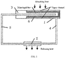
- the loop heat pipe mainly includes an evaporator 1, a condenser 2, a reservoir 3, a vapor line 4 and a liquid line 5.
- the whole cycle is as follows: liquid is evaporated on the outer surface of a capillary wick 6 in the evaporator 1, and absorbs heat outside the evaporator 1, and then generated vapor flows from the vapor line 4 to the condenser 2, and releases the heat in the condenser 2 to a heat sink, so as to condense the vapor into liquid, and finally the liquid flows into the reservoir 3 through the liquid line 5.
- a liquid working fluid in the reservoir 3 is maintained being supplied to the capillary wick in the evaporator 1.
- the flat plate loop heat pipes are mainly divided into two forms.
- the first form is a disc-shaped flat plate loop heat pipe, and an evaporator is in a disc shape, and the evaporator and a reservoir are separated by a capillary wick.
- the second form is a rectangular flat plate loop heat pipe, and a reservoir is arranged on one side of an evaporator.
- a Vapor Chamber (which is “Junreban” in Pinyin and is also translated as “Zhengqiqiang” in Pinyin) usually adopts a flat plate structure provided with a capillary wick. After the VC is filled with a working fluid, temperature equalization is realized through a gas-liquid phase change of the working fluid. When the VC is applied, heat sources (a chip or equipment) is attached to the VC, and heat conductive filler is used in an installation interface. There are mainly two application forms:
- the application of the VC has the following problems that: there is a conflict between improvement of the product properties and a requirement on the capillary wick.
- the capillary wick obtains a relatively high permeability by using a relatively large diameter and then increases the size of the VC, that is, increases the flowing length, so that the flowing resistance needs to be reduced, or then decreases the thickness of the VC, that is, decreases the flowing sectional area, so that the flowing resistance needs to be reduced.
- the present invention provides a vapor chamber based on a flat plate loop heat pipe, so as to improve the heat transfer capability, the ultimate heat flux and the anti-overload and anti-gravity working capability of the vapor chamber, increase the size of a heat spreading plate and decrease the thickness of the vapor chamber, and solve a conflicting requirement of the improvement of the properties of the vapor chamber for a diameter size of a capillary wick.
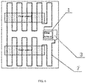
- the vapor chamber is attached to heat sources, and is characterized by including: a heat spreading plate and the flat plate loop heat pipe composed of an evaporator, a reservoir and a gas/liquid line.
- the flat plate loop heat pipe is pre-buried in the heat spreading plate.
- the evaporator is arranged at a position, attached to a biggest heat source in the heat sources, on the heat spreading plate.
- the reservoir is used to supply liquid to the evaporator.
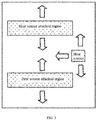
- Positions, attached to other heat sources except the biggest heat source in the heat sources, on the heat spreading plate are used as "heat source attached regions", and positions, not attached to the heat sources, on the heat spreading plate are used as "heat sink attached regions”.
- the gas/liquid line led out from an outlet of the evaporator is cyclically disposed between the "heat source attached regions" and the “heat sink attached regions” on the heat spreading plate, so that a liquid working fluid enters the "heat sink attached regions” after absorbing heat of the "heat source attached regions” and being evaporated into vapor, and a gas working fluid releases heat in the "heat sink attached regions” and is condensed into liquid; and circulation is performed hereby, and the working fluid finally flows back into the reservoir after being condensed by the "heat sink attached regions" into liquid, thus forming a loop.
- cold sources are arranged in the "heat sink attached regions" on one side or two sides of the heat spreading plate.
- the gas/liquid line led out from the outlet of the evaporator is cyclically disposed between the "heat sink attached regions" and the "heat source attached regions” on the heat spreading plate.
- the reservoir is suspended, and is not connected with the heat spreading plate in a heat conduction manner.
- the evaporator is exposed and directly attached to the biggest heat source in the heat sources.
- the gas/liquid line is firstly formed by a copper, stainless steel or titanium alloy pipeline sheet metal, and then pre-buried in the heat spreading plate in a gluing or welding manner.
- 1 evaporator; 2: condenser; 3: reservoir; 4: vapor line; 5: liquid line; 6: capillary wick; and 7: gas/liquid line
- the present embodiment provides a vapor chamber based on a flat plate loop heat pipe, which may solve a conflicting requirement of the improvement of the properties of the vapor chamber for a diameter size of a capillary wick.
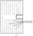
- a flat plate loop heat pipe composed of an evaporator, a reservoir and a gas/liquid line is pre-buried in an aluminum alloy heat spreading plate in a gluing or welding manner to form a vapor chamber based on the flat plate loop heat pipe.
- the vapor chamber is attached to a circuit board to be subjected to heat dissipation, so that the evaporator of the flat plate loop heat pipe is arranged in a region, attached to a biggest heat source (namely a position with the biggest heat generation amount of the circuit board) of the circuit board, on the vapor chamber.
- the side, provided with a vapor channel, of the evaporator is attached to the biggest heat source.
- the evaporator may be pre-buried into the aluminum alloy heat spreading plate, or is only fixed in the aluminum alloy heat spreading plate. The evaporator is exposed and directly attached to the biggest heat source.
- the liquid reservoir of the flat plate loop heat pipe is suspended, and is not connected with the aluminum alloy heat spreading plate in a heat conduction manner, so as to prevent heat leakage to the reservoir.
- "Heat sink attached regions” and "heat source attached regions” are arranged on the vapor chamber.
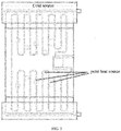
- the “heat source attached regions” are regions attached to heat sources (except the biggest heat source) on the circuit board, and the "heat sink attached regions” are regions adopting a cooling mode (cold sources) on the back surface of the vapor chamber, as shown in FIG. 5 .
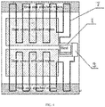
- the gas/liquid line led out from an outlet of the evaporator is cyclically disposed between the "heat sink attached regions" and the “heat source attached regions” on the vapor chamber.
- the gas/liquid line finally passes through the "heat sink attached regions” and then returns to the reservoir of the flat plate loop heat pipe, as shown in FIG. 4 .
- the gas/liquid line may be firstly formed by a copper, stainless steel or titanium alloy pipeline sheet metal, and then pre-buried in the aluminum alloy heat spreading plate in a gluing or welding manner.
- a working principle is that: since the evaporator of the flat plate loop heat pipe is attached to the biggest heat source, liquid is evaporated into vapor in the evaporator, and the vapor flows to the "heat sink attached regions" and releases heat, and then is condensed into liquid. Since the gas/liquid line is cyclically disposed between the "heat source attached regions" and the “heat sink attached regions”, a liquid working fluid absorbs heat in the "heat source attached regions” and then is evaporated into vapor, and the vapor releases heat in the "heat sink attached regions” and then is condensed into liquid. This cycle is performed for multiple times, and finally the working fluid flows back into the reservoir after being condensed by the "heat sink attached regions" into the liquid. In such cycle operation, a function of conducting the heat of one or more heat sources to the "heat sink attached regions" is realized.
- a main difference from the heat conductive vapor chamber is that: except “heat source attached regions” on the vapor chamber, other regions in no contact with heat sources are all used as “heat sink attached regions”. Therefore, a gas/liquid line is cyclically disposed between the "heat source attached regions” and other regions.
- the working principle of the heat spreading vapor chamber is the same as that of the heat conductive vapor chamber.
Landscapes
- Engineering & Computer Science (AREA)
- Life Sciences & Earth Sciences (AREA)
- Sustainable Development (AREA)
- Physics & Mathematics (AREA)
- Thermal Sciences (AREA)
- Mechanical Engineering (AREA)
- General Engineering & Computer Science (AREA)
- Cooling Or The Like Of Semiconductors Or Solid State Devices (AREA)
- Cooling Or The Like Of Electrical Apparatus (AREA)
Applications Claiming Priority (2)
| Application Number | Priority Date | Filing Date | Title |
|---|---|---|---|
| CN201710257571.7A CN107131784B (zh) | 2017-04-19 | 2017-04-19 | 基于平板环路热管的均热板 |
| PCT/CN2017/000655 WO2018191836A1 (fr) | 2017-04-19 | 2017-10-31 | Chambre à vapeur fondée sur tube caloporteur en boucle plate |
Publications (3)
| Publication Number | Publication Date |
|---|---|
| EP3614089A1 true EP3614089A1 (fr) | 2020-02-26 |
| EP3614089A4 EP3614089A4 (fr) | 2021-01-06 |
| EP3614089B1 EP3614089B1 (fr) | 2025-04-09 |
Family
ID=59715699
Family Applications (1)
| Application Number | Title | Priority Date | Filing Date |
|---|---|---|---|
| EP17906083.5A Active EP3614089B1 (fr) | 2017-04-19 | 2017-10-31 | Chambre à vapeur fondée sur tube caloporteur en boucle plate |
Country Status (4)
| Country | Link |
|---|---|
| US (1) | US20200116437A1 (fr) |
| EP (1) | EP3614089B1 (fr) |
| CN (1) | CN107131784B (fr) |
| WO (1) | WO2018191836A1 (fr) |
Families Citing this family (10)
| Publication number | Priority date | Publication date | Assignee | Title |
|---|---|---|---|---|
| US10831249B2 (en) * | 2017-03-02 | 2020-11-10 | Huawei Technologies Co., Ltd. | Heat conduction component and mobile terminal |
| CN107131784B (zh) * | 2017-04-19 | 2019-07-12 | 北京空间飞行器总体设计部 | 基于平板环路热管的均热板 |
| CN110262528B (zh) * | 2019-05-30 | 2022-07-29 | 北京空间飞行器总体设计部 | 一种月面探测器的起飞-着陆-移动实现方法 |
| CN111609743A (zh) * | 2020-04-27 | 2020-09-01 | 浙江嘉熙科技有限公司 | 热超导散热板、散热器及5g基站设备 |
| CN112113450A (zh) * | 2020-09-16 | 2020-12-22 | 武汉大学 | 一种用于航天电子散热用的振荡复合式毛细芯均热板结构 |
| US20240151478A1 (en) * | 2021-03-01 | 2024-05-09 | ShengRongYuan(Suzhou) Technology Co., Ltd | Loop heat pipe, and method and component for reducing heat transfer temperature difference of loop heat pipe |
| CN115087295A (zh) * | 2021-03-12 | 2022-09-20 | 北京小米移动软件有限公司 | 中框组件、中框组件的制造方法以及移动终端 |
| CN113453495B (zh) * | 2021-05-19 | 2022-06-24 | 江西新菲新材料有限公司 | 一种均热板及其电子设备 |
| US12512389B1 (en) * | 2022-05-02 | 2025-12-30 | Advanced Thermal Solutions, Inc. | Thermal management multi-loop transport apparatus, and related methods |
| US20250324539A1 (en) | 2024-04-12 | 2025-10-16 | Top Rank Technology Limited | Liquid cooling heat dissipation system |
Family Cites Families (12)
| Publication number | Priority date | Publication date | Assignee | Title |
|---|---|---|---|---|
| CN2372785Y (zh) * | 1999-05-28 | 2000-04-05 | 郭清松 | 用于电器的散热器 |
| CN101043806A (zh) * | 2006-03-20 | 2007-09-26 | 建准电机工业股份有限公司 | 复合式散热模组 |
| CN201044554Y (zh) * | 2007-02-07 | 2008-04-02 | 中国科学院工程热物理研究所 | 水冷式微槽群与热电组合激光器热控制系统 |
| CN101487584A (zh) * | 2009-02-25 | 2009-07-22 | 华南理工大学 | 一种大功率led灯的散热模组 |
| US9546826B1 (en) * | 2010-01-21 | 2017-01-17 | Hrl Laboratories, Llc | Microtruss based thermal heat spreading structures |
| WO2011130313A1 (fr) * | 2010-04-12 | 2011-10-20 | The Curators Of The University Of Missouri | Diffuseur de chaleur à circuits thermiques multiples |
| CN103189708B (zh) * | 2010-11-01 | 2015-04-01 | 富士通株式会社 | 环形热管以及利用该环形热管的电子设备 |
| CN102819303A (zh) * | 2011-06-09 | 2012-12-12 | 鸿富锦精密工业(深圳)有限公司 | 计算机机箱 |
| CN202630760U (zh) * | 2012-05-14 | 2012-12-26 | 南昌大学 | Led散热板式脉动热管 |
| CN103824826B (zh) * | 2014-02-21 | 2017-01-04 | 电子科技大学 | 一种微流道散热方法 |
| TWI580921B (zh) * | 2014-05-09 | 2017-05-01 | 財團法人工業技術研究院 | 脈衝型多管式熱管 |
| CN107131784B (zh) * | 2017-04-19 | 2019-07-12 | 北京空间飞行器总体设计部 | 基于平板环路热管的均热板 |
-
2017
- 2017-04-19 CN CN201710257571.7A patent/CN107131784B/zh active Active
- 2017-10-31 EP EP17906083.5A patent/EP3614089B1/fr active Active
- 2017-10-31 WO PCT/CN2017/000655 patent/WO2018191836A1/fr not_active Ceased
-
2019
- 2019-10-20 US US16/658,150 patent/US20200116437A1/en not_active Abandoned
Also Published As
| Publication number | Publication date |
|---|---|
| CN107131784A (zh) | 2017-09-05 |
| EP3614089B1 (fr) | 2025-04-09 |
| EP3614089A4 (fr) | 2021-01-06 |
| CN107131784B (zh) | 2019-07-12 |
| WO2018191836A1 (fr) | 2018-10-25 |
| US20200116437A1 (en) | 2020-04-16 |
Similar Documents
| Publication | Publication Date | Title |
|---|---|---|
| EP3614089B1 (fr) | Chambre à vapeur fondée sur tube caloporteur en boucle plate | |
| CN108168342B (zh) | 高热流反重力热管 | |
| CN104851857B (zh) | 一种芯片冷却系统 | |
| EP2154461A1 (fr) | Dispositif caloduc en boucle a temperature uniforme | |
| CN105277028A (zh) | 一体化结构热控环路热管 | |
| TW200643362A (en) | Loop-type heat exchange apparatus | |
| WO2018191834A1 (fr) | Système de refroidissement d'ordinateur portable basé sur un caloduc à boucle plate | |
| CN202902952U (zh) | 循环式热虹吸散热装置 | |
| CN108362148A (zh) | 组合式冷板 | |
| CN108471693A (zh) | 一种蒸发式散热系统 | |
| US20130312938A1 (en) | Heat pipe with vaporized working fluid flow accelerator | |
| CN102646651B (zh) | 薄型热板结构 | |
| WO2012152018A1 (fr) | Echangeur de chaleur du type à tube caloporteur plan | |
| CN107120741A (zh) | 散热装置和空调器 | |
| WO2019037392A1 (fr) | Radiateur, unité extérieure, et climatiseur | |
| CN112050674A (zh) | 变散热冷凝器和环路热管 | |
| CN207610584U (zh) | 一种微通道散热装置 | |
| CN103673172A (zh) | 一种热管换热式半导体制冷装置 | |
| CN104296574A (zh) | 热管及其传热方法 | |
| US20070034358A1 (en) | Heat dissipation device | |
| CN218183789U (zh) | 一种环形式的散热装置 | |
| CN107087375B (zh) | 一种蒸发室和蒸汽管道不直接连通的平板式环路热管 | |
| CN106455431B (zh) | 板式环路热虹吸均温板 | |
| CN208818050U (zh) | 一种平板式环路热管 | |
| JP3176377U (ja) | 熱管放熱改良構造 |
Legal Events
| Date | Code | Title | Description |
|---|---|---|---|
| STAA | Information on the status of an ep patent application or granted ep patent |
Free format text: STATUS: THE INTERNATIONAL PUBLICATION HAS BEEN MADE |
|
| PUAI | Public reference made under article 153(3) epc to a published international application that has entered the european phase |
Free format text: ORIGINAL CODE: 0009012 |
|
| STAA | Information on the status of an ep patent application or granted ep patent |
Free format text: STATUS: REQUEST FOR EXAMINATION WAS MADE |
|
| 17P | Request for examination filed |
Effective date: 20191007 |
|
| AK | Designated contracting states |
Kind code of ref document: A1 Designated state(s): AL AT BE BG CH CY CZ DE DK EE ES FI FR GB GR HR HU IE IS IT LI LT LU LV MC MK MT NL NO PL PT RO RS SE SI SK SM TR |
|
| AX | Request for extension of the european patent |
Extension state: BA ME |
|
| DAV | Request for validation of the european patent (deleted) | ||
| DAX | Request for extension of the european patent (deleted) | ||
| A4 | Supplementary search report drawn up and despatched |
Effective date: 20201209 |
|
| RIC1 | Information provided on ipc code assigned before grant |
Ipc: F28D 15/04 20060101AFI20201203BHEP Ipc: F28D 15/02 20060101ALI20201203BHEP Ipc: H01L 23/427 20060101ALI20201203BHEP |
|
| GRAP | Despatch of communication of intention to grant a patent |
Free format text: ORIGINAL CODE: EPIDOSNIGR1 |
|
| STAA | Information on the status of an ep patent application or granted ep patent |
Free format text: STATUS: GRANT OF PATENT IS INTENDED |
|
| INTG | Intention to grant announced |
Effective date: 20241030 |
|
| GRAS | Grant fee paid |
Free format text: ORIGINAL CODE: EPIDOSNIGR3 |
|
| GRAA | (expected) grant |
Free format text: ORIGINAL CODE: 0009210 |
|
| STAA | Information on the status of an ep patent application or granted ep patent |
Free format text: STATUS: THE PATENT HAS BEEN GRANTED |
|
| AK | Designated contracting states |
Kind code of ref document: B1 Designated state(s): AL AT BE BG CH CY CZ DE DK EE ES FI FR GB GR HR HU IE IS IT LI LT LU LV MC MK MT NL NO PL PT RO RS SE SI SK SM TR |
|
| REG | Reference to a national code |
Ref country code: GB Ref legal event code: FG4D |
|
| REG | Reference to a national code |
Ref country code: CH Ref legal event code: EP |
|
| REG | Reference to a national code |
Ref country code: DE Ref legal event code: R096 Ref document number: 602017088875 Country of ref document: DE |
|
| REG | Reference to a national code |
Ref country code: IE Ref legal event code: FG4D |
|
| REG | Reference to a national code |
Ref country code: NL Ref legal event code: MP Effective date: 20250409 |
|
| PG25 | Lapsed in a contracting state [announced via postgrant information from national office to epo] |
Ref country code: NL Free format text: LAPSE BECAUSE OF FAILURE TO SUBMIT A TRANSLATION OF THE DESCRIPTION OR TO PAY THE FEE WITHIN THE PRESCRIBED TIME-LIMIT Effective date: 20250409 |
|
| REG | Reference to a national code |
Ref country code: AT Ref legal event code: MK05 Ref document number: 1783848 Country of ref document: AT Kind code of ref document: T Effective date: 20250409 |
|
| PG25 | Lapsed in a contracting state [announced via postgrant information from national office to epo] |
Ref country code: PT Free format text: LAPSE BECAUSE OF FAILURE TO SUBMIT A TRANSLATION OF THE DESCRIPTION OR TO PAY THE FEE WITHIN THE PRESCRIBED TIME-LIMIT Effective date: 20250811 Ref country code: FI Free format text: LAPSE BECAUSE OF FAILURE TO SUBMIT A TRANSLATION OF THE DESCRIPTION OR TO PAY THE FEE WITHIN THE PRESCRIBED TIME-LIMIT Effective date: 20250409 Ref country code: ES Free format text: LAPSE BECAUSE OF FAILURE TO SUBMIT A TRANSLATION OF THE DESCRIPTION OR TO PAY THE FEE WITHIN THE PRESCRIBED TIME-LIMIT Effective date: 20250409 |
|
| REG | Reference to a national code |
Ref country code: LT Ref legal event code: MG9D |
|
| PG25 | Lapsed in a contracting state [announced via postgrant information from national office to epo] |
Ref country code: GR Free format text: LAPSE BECAUSE OF FAILURE TO SUBMIT A TRANSLATION OF THE DESCRIPTION OR TO PAY THE FEE WITHIN THE PRESCRIBED TIME-LIMIT Effective date: 20250710 Ref country code: NO Free format text: LAPSE BECAUSE OF FAILURE TO SUBMIT A TRANSLATION OF THE DESCRIPTION OR TO PAY THE FEE WITHIN THE PRESCRIBED TIME-LIMIT Effective date: 20250709 |
|
| PG25 | Lapsed in a contracting state [announced via postgrant information from national office to epo] |
Ref country code: PL Free format text: LAPSE BECAUSE OF FAILURE TO SUBMIT A TRANSLATION OF THE DESCRIPTION OR TO PAY THE FEE WITHIN THE PRESCRIBED TIME-LIMIT Effective date: 20250409 |
|
| PG25 | Lapsed in a contracting state [announced via postgrant information from national office to epo] |
Ref country code: BG Free format text: LAPSE BECAUSE OF FAILURE TO SUBMIT A TRANSLATION OF THE DESCRIPTION OR TO PAY THE FEE WITHIN THE PRESCRIBED TIME-LIMIT Effective date: 20250409 |
|
| PG25 | Lapsed in a contracting state [announced via postgrant information from national office to epo] |
Ref country code: HR Free format text: LAPSE BECAUSE OF FAILURE TO SUBMIT A TRANSLATION OF THE DESCRIPTION OR TO PAY THE FEE WITHIN THE PRESCRIBED TIME-LIMIT Effective date: 20250409 |
|
| PG25 | Lapsed in a contracting state [announced via postgrant information from national office to epo] |
Ref country code: AT Free format text: LAPSE BECAUSE OF FAILURE TO SUBMIT A TRANSLATION OF THE DESCRIPTION OR TO PAY THE FEE WITHIN THE PRESCRIBED TIME-LIMIT Effective date: 20250409 |
|
| PG25 | Lapsed in a contracting state [announced via postgrant information from national office to epo] |
Ref country code: RS Free format text: LAPSE BECAUSE OF FAILURE TO SUBMIT A TRANSLATION OF THE DESCRIPTION OR TO PAY THE FEE WITHIN THE PRESCRIBED TIME-LIMIT Effective date: 20250709 |
|
| PG25 | Lapsed in a contracting state [announced via postgrant information from national office to epo] |
Ref country code: IS Free format text: LAPSE BECAUSE OF FAILURE TO SUBMIT A TRANSLATION OF THE DESCRIPTION OR TO PAY THE FEE WITHIN THE PRESCRIBED TIME-LIMIT Effective date: 20250809 |
|
| PG25 | Lapsed in a contracting state [announced via postgrant information from national office to epo] |
Ref country code: LV Free format text: LAPSE BECAUSE OF FAILURE TO SUBMIT A TRANSLATION OF THE DESCRIPTION OR TO PAY THE FEE WITHIN THE PRESCRIBED TIME-LIMIT Effective date: 20250409 |
|
| PGFP | Annual fee paid to national office [announced via postgrant information from national office to epo] |
Ref country code: DE Payment date: 20251126 Year of fee payment: 9 |
|
| REG | Reference to a national code |
Ref country code: DE Ref legal event code: R097 Ref document number: 602017088875 Country of ref document: DE |
|
| PG25 | Lapsed in a contracting state [announced via postgrant information from national office to epo] |
Ref country code: SM Free format text: LAPSE BECAUSE OF FAILURE TO SUBMIT A TRANSLATION OF THE DESCRIPTION OR TO PAY THE FEE WITHIN THE PRESCRIBED TIME-LIMIT Effective date: 20250409 Ref country code: DK Free format text: LAPSE BECAUSE OF FAILURE TO SUBMIT A TRANSLATION OF THE DESCRIPTION OR TO PAY THE FEE WITHIN THE PRESCRIBED TIME-LIMIT Effective date: 20250409 |
|
| PGFP | Annual fee paid to national office [announced via postgrant information from national office to epo] |
Ref country code: FR Payment date: 20251031 Year of fee payment: 9 |
|
| PG25 | Lapsed in a contracting state [announced via postgrant information from national office to epo] |
Ref country code: CZ Free format text: LAPSE BECAUSE OF FAILURE TO SUBMIT A TRANSLATION OF THE DESCRIPTION OR TO PAY THE FEE WITHIN THE PRESCRIBED TIME-LIMIT Effective date: 20250409 |
|
| PG25 | Lapsed in a contracting state [announced via postgrant information from national office to epo] |
Ref country code: EE Free format text: LAPSE BECAUSE OF FAILURE TO SUBMIT A TRANSLATION OF THE DESCRIPTION OR TO PAY THE FEE WITHIN THE PRESCRIBED TIME-LIMIT Effective date: 20250409 |
|
| PG25 | Lapsed in a contracting state [announced via postgrant information from national office to epo] |
Ref country code: SK Free format text: LAPSE BECAUSE OF FAILURE TO SUBMIT A TRANSLATION OF THE DESCRIPTION OR TO PAY THE FEE WITHIN THE PRESCRIBED TIME-LIMIT Effective date: 20250409 Ref country code: RO Free format text: LAPSE BECAUSE OF FAILURE TO SUBMIT A TRANSLATION OF THE DESCRIPTION OR TO PAY THE FEE WITHIN THE PRESCRIBED TIME-LIMIT Effective date: 20250409 |
|
| PG25 | Lapsed in a contracting state [announced via postgrant information from national office to epo] |
Ref country code: IT Free format text: LAPSE BECAUSE OF FAILURE TO SUBMIT A TRANSLATION OF THE DESCRIPTION OR TO PAY THE FEE WITHIN THE PRESCRIBED TIME-LIMIT Effective date: 20250409 |
|
| PLBE | No opposition filed within time limit |
Free format text: ORIGINAL CODE: 0009261 |
|
| STAA | Information on the status of an ep patent application or granted ep patent |
Free format text: STATUS: NO OPPOSITION FILED WITHIN TIME LIMIT |
|
| REG | Reference to a national code |
Ref country code: CH Ref legal event code: L10 Free format text: ST27 STATUS EVENT CODE: U-0-0-L10-L00 (AS PROVIDED BY THE NATIONAL OFFICE) Effective date: 20260218 |
|
| 26N | No opposition filed |
Effective date: 20260112 |