EP3614100A1 - Dispositif de nivellement de masses de coulée telle qu'une chape, béton pompé ou analogues ainsi que dispositif de mesure doté d'un tel dispositif - Google Patents
Dispositif de nivellement de masses de coulée telle qu'une chape, béton pompé ou analogues ainsi que dispositif de mesure doté d'un tel dispositif Download PDFInfo
- Publication number
- EP3614100A1 EP3614100A1 EP19191901.8A EP19191901A EP3614100A1 EP 3614100 A1 EP3614100 A1 EP 3614100A1 EP 19191901 A EP19191901 A EP 19191901A EP 3614100 A1 EP3614100 A1 EP 3614100A1
- Authority
- EP
- European Patent Office
- Prior art keywords
- marking
- leveling
- height
- casting compound
- measuring device
- Prior art date
- Legal status (The legal status is an assumption and is not a legal conclusion. Google has not performed a legal analysis and makes no representation as to the accuracy of the status listed.)
- Granted
Links
Images


Classifications
-
- G—PHYSICS
- G01—MEASURING; TESTING
- G01C—MEASURING DISTANCES, LEVELS OR BEARINGS; SURVEYING; NAVIGATION; GYROSCOPIC INSTRUMENTS; PHOTOGRAMMETRY OR VIDEOGRAMMETRY
- G01C15/00—Surveying instruments or accessories not provided for in groups G01C1/00 - G01C13/00
- G01C15/002—Active optical surveying means
- G01C15/004—Reference lines, planes or sectors
-
- E—FIXED CONSTRUCTIONS
- E04—BUILDING
- E04G—SCAFFOLDING; FORMS; SHUTTERING; BUILDING IMPLEMENTS OR AIDS, OR THEIR USE; HANDLING BUILDING MATERIALS ON THE SITE; REPAIRING, BREAKING-UP OR OTHER WORK ON EXISTING BUILDINGS
- E04G21/00—Preparing, conveying, or working-up building materials or building elements in situ; Other devices or measures for constructional work
- E04G21/02—Conveying or working-up concrete or similar masses able to be heaped or cast
- E04G21/10—Devices for levelling, e.g. templates or boards
-
- G—PHYSICS
- G01—MEASURING; TESTING
- G01C—MEASURING DISTANCES, LEVELS OR BEARINGS; SURVEYING; NAVIGATION; GYROSCOPIC INSTRUMENTS; PHOTOGRAMMETRY OR VIDEOGRAMMETRY
- G01C5/00—Measuring height; Measuring distances transverse to line of sight; Levelling between separated points; Surveyors' levels
Definitions
- the present invention relates to a device for leveling casting compounds such as liquid screed, pumped concrete or the like. Furthermore, the invention relates to a measuring device with such a device.
- leveling should be understood to mean filling in particular a space with the casting compound to the desired height.
- Floating screed is an example of pouring compound to be emphasized.
- a pouring compound is to be understood as a mass which is so liquid when introduced into the room that it can be conveyed by means of a feed pump. Once the desired volume of casting compound has been introduced into the room, the casting compound is allowed to dry for a certain time, as a result of which the casting compound hardens. Due to the fact that the casting compound is liquid during introduction into the room, it distributes itself more or less quickly evenly in the room and assumes a uniform level. It is therefore not necessary to smooth the casting compound.
- leveling blocks In order to be able to level a room to the desired height with liquid screed, so-called leveling blocks are used, such as those from the DE 100 49 867 A1 or the DE 200 17 303 U1 are known.
- leveling brackets usually have three legs on which a threaded rod is attached, along which a level plate can be moved by turning.
- the leveling stand is placed on the floor of the room that is to be filled with the casting compound.
- the casting compound is pumped into the room with a feed pump until the surface of the casting compound is flush with the leveling disc.
- the casting mass is now at the desired height. Then the leveling stand is removed.
- a device which is not unlike a trestle is in the US 6 760 974 B1 disclosed.
- This device has a plurality of tubes arranged telescopically and displaceable relative to one another.
- the pipes are arranged vertically when used as intended.
- At the bottom tube there is a base that can be placed on the floor of the room.
- a height indicator is arranged on the lowest tube, which has a similar function as the leveling disc of a leveling block.
- the height indicator can be adjusted to the desired height by moving the pipes relative to each other. With the help of locking elements, the displaceability of the pipes can be prevented if the height indicator is set to the desired height. Similar to the leveling stand, the desired height of the casting compound is reached when the surface of the casting compound is flush with the height indicator.
- a leveling block allows the casting compound to be leveled only at one point in the room.
- the height of the casting compound should be determined at several points in the room. Therefore, several leveling stands are used.
- the leveling blocks of the respective rooms must be set to a different level, which is cumbersome and time-consuming and can cause errors.
- leveling trestles represent a certain obstacle. It is not uncommon for people to get caught on the leveling trestles and stumble. If the leveling bracket falls into the liquid screed when it falls over, the leveling bracket must then be cleaned thoroughly and time-consuming.
- the casting compound has the desired height when it is flush with the level plate.
- the leveling stand is therefore up to the level disc in the casting compound, so that it must be cleaned thoroughly even after operation. The more leveling blocks are used, the greater the cleaning effort.
- AT 514 294 A1 discloses a device for leveling fill, in which a pull-off strip is pulled over the fill in a manner similar to a rake in order to bring it to a uniform height.
- the device disclosed there is only suitable for solids, but not for casting compounds which can be conveyed with a feed pump.
- An object of an embodiment of the present invention is to provide a device with which it is possible with simple means to cast a casting compound with high accuracy and reliability with a reduced expenditure of time compared to the leveling trestles discussed above to level. In particular, the cleaning effort should be reduced and the risk of getting caught and stumbling should be prevented. Furthermore, an embodiment of the present invention has for its object to provide a measuring device which, even in large rooms and in several rooms with different floor levels, enables a casting compound to be leveled in a simple and at least almost error-free manner with little expenditure of time.
- One embodiment of the invention relates to a device for leveling casting compounds such as self-leveling screed, pumped concrete or the like, comprising a buoyancy body which floats on the casting compound to be leveled, a marking section which is designed as a marking body connected to the buoyancy body or is formed by the buoyancy body, and a marking arranged on the marking section, with which the height of the casting compound can be determined.
- the buoyancy body is plate-shaped or disk-shaped.
- the marking body can be designed as a tube or funnel-shaped.
- the sources used to determine the height of the casting compound for generating electromagnetic waves may only be arranged at a certain distance from the floor of the space to be filled with the casting compound. To bridge the gap, the marker body must be made long enough. Adjusting the length of the marker body is very easy to do with a tube.
- the marking on the pipe can be read equally well from all sides. In addition, a pipe can be easily gripped so that the device is easy to handle.
- the diameter of the marking body widens towards the buoyancy body. Ideally, the funnel-shaped marking body is flush with the buoyancy body.
- the funnel-shaped design has the additional advantage that the casting compound can run off and areas that are difficult to access can be avoided.
- the surface of the marking body can be flat in relation to a sectional plane running through the central axis of the marking body, so that a conical section is created. Alternatively, the surface can be curved. It also increases the funnel-shaped Design of the marker body, the stability of the device.
- the buoyancy body and the marking body can be designed as separate components and connected to one another by suitable means.
- the bodies of the device do not have to be connected to one another in an additional operation. Detachment of the bodies from one another is also prevented.
- a further developed embodiment is characterized in that the device has a coupling unit for coupling the device to a coupling partner.
- the proposed device floats on the casting compound. It is therefore located close to the ground.
- the coupling partner can comprise a rod which can interact with the coupling unit. With the coupling partner, the device can be quickly and easily distributed in the room. It is therefore possible in a simple manner to determine the height of the casting compound at several points in the room with only one device during the filling of the casting compound, as a result of which the determination is very precise.
- the coupling unit is designed as a hook or an eyelet.
- Hooks and eyes are simple embodiments of the coupling unit that can be gripped well with the coupling partner. Also detaching the coupling partner from the coupling unit is easy to do. Alternatively, magnets or the like can also be used.
- Another embodiment is characterized in that the marking is designed for interaction with electromagnetic waves.
- the use of electromagnetic waves enables very precise leveling, since these can be emitted in a very precisely defined plane with almost no height deviations.
- the waves have no significant disturbing influence on the work to be carried out in the room.
- the proposed device can be used for very precise leveling in this embodiment.
- the interaction with the electromagnetic waves can take place, for example, in that the electromagnetic waves are reflected in a defined manner by the marking, so that the reflected electromagnetic waves can be received by a detector when the electromagnetic waves hit the marking. When the electromagnetic waves hit the marking, the desired height of the casting mass is reached.
- the device has a sensor which registers the interaction of the marking with the electromagnetic waves and which generates a corresponding signal.
- the sensor can be configured as a photodiode.
- the photodiode When a light beam hits the marking, the photodiode generates a corresponding signal, which can be transmitted to a receiver, for example, which emits an acoustic or optical signal.
- the receiver can be arranged in the device itself, but the receiver can also be located at the light source or at any one other device. Integration into a smartphone application is conceivable, so that a responsible person receives an indication that the casting compound has reached the desired height, even if this person is further away from the rooms in question.
- One embodiment of the invention relates to a measuring device for leveling casting compounds such as self-leveling screed, pump concrete or the like, comprising a source for generating and for the height-defined transmission of electromagnetic waves, and at least one device according to one of the preceding embodiments, the marking with the electromagnetic waves for leveling the casting compounds interact.
- the source with which the electromagnetic waves are generated must be aligned as precisely as possible horizontally and brought to a height which, when the electromagnetic waves interact with the marking, indicates that the casting compound has reached the desired height. It is sufficient to use only one device, while when using leveling trestles, in particular in larger or several rooms, each of the leveling trestles used has to be set to the desired height of the casting compound. When using the proposed device, this is not necessary even if Rooms with different floor levels are to be filled with the casting compound.
- the source can be designed as a laser source that generates laser beams.
- Laser beams are often used to determine distances, so that laser sources are widespread and therefore quickly and inexpensively available.
- the measuring device comprises a stand for receiving the source.
- the tripod ensures that the source is safely picked up and the risk of tipping over is kept low.
- the stand has a height-adjustable holder for the source.
- the electromagnetic waves can be emitted horizontally at the desired height with sufficient accuracy.
- the measuring device comprises a coupling partner for coupling with the device.
- the coupling partner can comprise a rod which can interact with the coupling unit.
- the device can be quickly and easily distributed and collected in the room without a person having to bend down.
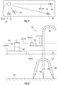
- FIG. 1 A first exemplary embodiment of a device 10 1 according to the invention for leveling casting compounds 12 such as liquid screed, pumped concrete or the like (see FIG. 6) is shown on the basis of a basic side view.
- the device 10 1 comprises a buoyancy body 14, which floats on the casting compound 12 to be leveled, a marking section 16, which as one with the buoyancy body 14 connected marking body 18 is formed, and a marking 20 arranged on the marking section 16, with which the height of the casting compound 12 can be determined.
- the marking 20 is designed as a colored line, in particular as a black line that stands out clearly from the marking body 18.
- the buoyancy body 14 is plate-shaped and has a rectangular cross section in the plan view (see Figure 5 ).
- the buoyancy provided by the buoyancy body 14 is selected in such a way that it holds the entire device 10 1 upright on the casting compound 12 and virtually does not immerse into the casting compound 12.
- the device 10 1 and in particular the buoyancy body 14 are designed such that the underside of the buoyancy body 14 is almost flush with the surface of the casting compound 12 (cf. Figure 6 ).
- the marking body 18 is designed as a tube 22 and connected to the buoyancy body 14 in a suitable manner.
- the tube 22 can be welded to the buoyancy body 14.
- the marking 20 is arranged on the tube 22.
- An embodiment is not shown in which the marking body 18 and the buoyancy body 14 are made in one piece.
- the device 10 1 has a coupling unit 24, which in the exemplary embodiments shown is designed as a hook 26.
- FIG. 2 A second exemplary embodiment of the device 10 2 according to the invention is shown on the basis of a basic side sectional view.
- the structure of the device 10 1 according to the second embodiment essentially corresponds the structure of the device 10 1 according to the first embodiment, the marking body 18 of the device 10 2 according to the second embodiment being funnel-shaped.
- the diameter of the marking body 18 initially remains constant, so that the marking body 18 in the second exemplary embodiment has a tubular section. Thereafter, the diameter of the marking body 18 increases constantly towards the buoyancy body 14 until the diameter of the marking body 18 and the buoyancy body 14 are the same. Consequently, the marking body 18 has a funnel-shaped and in this case conical section. This increases the stability of the device 10 2 and simplifies cleaning due to the good accessibility of the surfaces.
- the device 10 2 according to the second embodiment is made in one piece, the buoyancy body 14 and the marking body 18 consequently form a coherent component.
- FIG 3 A third exemplary embodiment of a device 10 3 according to the invention is shown on the basis of a basic side view.
- the structure of the device 10 3 according to the third exemplary embodiment essentially corresponds to the structure of the device 10 1 according to the first exemplary embodiment, the marking 20 being designed for interaction with electromagnetic waves 40 (see Figure 5 ).
- the marking 20 does not necessarily have to be visible to the human eye.
- the device 10 3 has a sensor 30 which monitors the interaction the mark 20 registered with the electromagnetic waves 40 and which generates a corresponding signal.
- a coupling partner 32 is shown on the basis of a basic illustration, which can be coupled to the device 10 according to one of the exemplary embodiments.
- the coupling partner 32 has a rod 33, on which a hook 34 is arranged at one end, which can be brought into engagement with the hook 26 of the device 10.
- Figure 5 shows a basic plan view and Figure 6 a side view of a measuring device 36 according to the invention for leveling casting compounds 12 such as liquid screed, pumped concrete or the like.
- the measuring device 36 comprises a source 38 for generating and for the height-defined transmission of electromagnetic waves 40 and a device 10 according to one of the previous exemplary embodiments.
- the Figure 5 is to be understood in such a way that the same device 10 is arranged at different times in four different locations. Alternatively, several devices 10 can also be used at the same time, but this is not absolutely necessary.
- the source 38 is designed as a laser source 42, which generates laser beams 44 and emits them in 360 °.
- the measuring device 36 comprises a height-adjustable stand 46 for receiving the source 38, the stand 46 having three legs 48 which taper to a point at their free ends. It should be noted that the illustrated relationship of the stand 46 to the device 10 does not correspond to the actual conditions. Usually the device 10 and the stand 46 are approximately the same height.
- the measuring device 36 is operated in the following way:
- the stand 46 is placed on a floor 49 of a room 50 which is to be filled with a casting compound 12, for example with a liquid screed.
- the laser source 42 is then firmly connected to a receptacle 52 of the stand 46.
- the laser source 42 can be self-leveling, so that it is not necessary to align the laser source 42 exactly horizontally.
- the receptacle 52 is adjustable in height. The procedure for arranging the laser source 42 at the correct height is as follows.
- a so-called meter crack can be used as the starting point for the calculation of the height at which the laser source 42 has to be arranged, which is to be understood as meaning a line marking applied to the walls of a shell.
- a meter crack with the designation OKFF + 1.00 m can be used, the designation OKFF standing for "top edge of the finished floor”.
- the meter crack OKFF + 1.00 m is therefore 1 m above the top edge of the finished floor.
- the height of the floor covering for example a laminate of 0.01 m height
- the value is 1.01 m, which has to be subtracted from the meter crack OKFF + 1m.
- This value still has to be corrected by the height HM of the marking 20 of the device 10, which can be, for example, 0.2 m.
- the laser source 42 must therefore be set to a height of 0.81 m below the meter crack so that the laser beam 44 hits the marking 20 when the desired height HGW of the casting compound 12 has been reached.
- the distance of 0.81 m below the meter crack can be marked by means of a line on the wall of the room, so that the laser beams 44 emitted by the laser source 42 can be aligned with this line.
- the laser source 42 After the laser source 42 has been aligned, one of the devices 10 according to the invention with the coupling partner 24 is arranged anywhere in the room 50.
- the laser source 42 is now switched on. Like from the Figures 5 and 6 As can be seen, the laser source 42 emits the laser beams 44 in an almost horizontal plane through the entire or almost the entire space 50, wherein a sector-shaped radiation is also conceivable.
- the casting compound 12 is conveyed into the space 50 by means of a feed pump, not shown.
- the level of the casting compound 12 gradually increases.
- the current height of the casting compound 12 is in Figure 6 designated with HGA.
- the device 10 As the volume of the casting compound 12 pumped into the space 50, the device 10 is also raised.
- the laser beams 44 strike the marking 20 of the device 10 when the casting compound 12 has reached the desired height HGW.
- the marker 20 is not designed to interact with the laser beams 44, the person must observe the device 10 and check the position of the laser beams 44. If it detects that the laser beams 44 hit the mark 20 or are just before it, it switches off the feed pump. In order to make it easier to check the position of the laser beams 44 on the marking section 16, the latter can be designed in particular in terms of color that the laser beams 44 are particularly well visible when they hit the marking 20.
- the marking 20 is designed to interact with the electromagnetic waves 40, in this case with the laser beams 44.
- the sensor 30 registers the impact of the laser beams 44 on the marking 20 and generates a corresponding signal, for example an optical or an acoustic signal.
- the device 10 3 according to the third exemplary embodiment has two LEDs 58 (see Figure 3 ), which in this case output an optical signal.
- the lower one of the LEDs 58 can light up when the casting compound 12 has not yet reached the desired height HMW. If the desired height HMW is exceeded, the upper of the LEDs 58 can light up. If the desired height HMW is reached, a responsible person can stop the feed pump. Alternatively or cumulatively, the sensor 30 can also generate a radio signal which is sent to a person's smartphone.
- the person collects the device 10 with the coupling partner 32 and takes the stand 46 together with the laser source 42 from the casting compound 12 Figure 6 recognizable, the stand 46 has a holding section 56 with which the person can grip the stand 46.
- the desired height HGW of the casting compound 12 is usually not very large. Typical heights, which can also be referred to as layer thicknesses, are between 2 and 20 cm, in most cases the layer thicknesses being less than 7 cm.
- the tripod 46 must be designed so that the Laser source 42 can be arranged at a correspondingly small distance above the floor 49 of the room 50.
- the height HM of the marking can also be adapted so that the desired height of the casting compound can be determined with commercially available laser sources and with the necessary precision, even in the case of thin layers.
- the marking body 18 designed as the tube 22 can be made correspondingly longer. It is also conceivable to plug an extension onto the marking body 18, which has a marking, so as to increase the height HM of the marking.
Landscapes
- Engineering & Computer Science (AREA)
- Physics & Mathematics (AREA)
- General Physics & Mathematics (AREA)
- Radar, Positioning & Navigation (AREA)
- Remote Sensing (AREA)
- Architecture (AREA)
- Mechanical Engineering (AREA)
- Civil Engineering (AREA)
- Structural Engineering (AREA)
- Level Indicators Using A Float (AREA)
- Measurement Of Levels Of Liquids Or Fluent Solid Materials (AREA)
- Road Paving Machines (AREA)
- On-Site Construction Work That Accompanies The Preparation And Application Of Concrete (AREA)
Applications Claiming Priority (1)
| Application Number | Priority Date | Filing Date | Title |
|---|---|---|---|
| DE102018120299.7A DE102018120299A1 (de) | 2018-08-21 | 2018-08-21 | Vorrichtung zum Nivellieren von Gussmassen wie Fließestrich, Pumpbeton oder dergleichen sowie Messeinrichtung mit einer derartigen Vorrichtung |
Publications (3)
| Publication Number | Publication Date |
|---|---|
| EP3614100A1 true EP3614100A1 (fr) | 2020-02-26 |
| EP3614100B1 EP3614100B1 (fr) | 2023-06-07 |
| EP3614100C0 EP3614100C0 (fr) | 2023-06-07 |
Family
ID=67659028
Family Applications (1)
| Application Number | Title | Priority Date | Filing Date |
|---|---|---|---|
| EP19191901.8A Active EP3614100B1 (fr) | 2018-08-21 | 2019-08-15 | Dispositif de nivellement de masses de coulée telle qu'une chape ou béton pompé ainsi que dispositif de mesure doté d'un tel dispositif |
Country Status (4)
| Country | Link |
|---|---|
| EP (1) | EP3614100B1 (fr) |
| DE (1) | DE102018120299A1 (fr) |
| ES (1) | ES2950802T3 (fr) |
| PL (1) | PL3614100T3 (fr) |
Cited By (2)
| Publication number | Priority date | Publication date | Assignee | Title |
|---|---|---|---|---|
| CN111852050A (zh) * | 2020-08-06 | 2020-10-30 | 中国建筑第八工程局有限公司 | 钢结构球节点定位辅助装置及定位方法 |
| DE102020123727A1 (de) | 2020-09-11 | 2022-03-17 | Christoph Wagner | Markierungsvorrichtung und Verfahren zur Höhenmarkierung |
Citations (4)
| Publication number | Priority date | Publication date | Assignee | Title |
|---|---|---|---|---|
| DE20017303U1 (de) | 2000-10-09 | 2001-02-15 | Eckert, Herbert, 66822 Lebach | Nivellierbock |
| DE10049867A1 (de) | 2000-10-09 | 2002-04-25 | Herbert Eckert | Nivellierbock |
| US6760974B1 (en) | 2003-04-29 | 2004-07-13 | Maxxon Corporation | Height determining instrument for poured floors, and method |
| AT514294A1 (de) | 2013-05-14 | 2014-11-15 | Egon Döberl | Vorrichtung zur Nivellierung von Schüttungen und Baustoffen |
-
2018
- 2018-08-21 DE DE102018120299.7A patent/DE102018120299A1/de not_active Ceased
-
2019
- 2019-08-15 ES ES19191901T patent/ES2950802T3/es active Active
- 2019-08-15 EP EP19191901.8A patent/EP3614100B1/fr active Active
- 2019-08-15 PL PL19191901.8T patent/PL3614100T3/pl unknown
Patent Citations (4)
| Publication number | Priority date | Publication date | Assignee | Title |
|---|---|---|---|---|
| DE20017303U1 (de) | 2000-10-09 | 2001-02-15 | Eckert, Herbert, 66822 Lebach | Nivellierbock |
| DE10049867A1 (de) | 2000-10-09 | 2002-04-25 | Herbert Eckert | Nivellierbock |
| US6760974B1 (en) | 2003-04-29 | 2004-07-13 | Maxxon Corporation | Height determining instrument for poured floors, and method |
| AT514294A1 (de) | 2013-05-14 | 2014-11-15 | Egon Döberl | Vorrichtung zur Nivellierung von Schüttungen und Baustoffen |
Cited By (3)
| Publication number | Priority date | Publication date | Assignee | Title |
|---|---|---|---|---|
| CN111852050A (zh) * | 2020-08-06 | 2020-10-30 | 中国建筑第八工程局有限公司 | 钢结构球节点定位辅助装置及定位方法 |
| DE102020123727A1 (de) | 2020-09-11 | 2022-03-17 | Christoph Wagner | Markierungsvorrichtung und Verfahren zur Höhenmarkierung |
| DE102020123727B4 (de) | 2020-09-11 | 2022-08-11 | Christoph Wagner | Markierungsvorrichtung und Verfahren zur Höhenmarkierung |
Also Published As
| Publication number | Publication date |
|---|---|
| EP3614100B1 (fr) | 2023-06-07 |
| PL3614100T3 (pl) | 2023-09-11 |
| EP3614100C0 (fr) | 2023-06-07 |
| ES2950802T3 (es) | 2023-10-13 |
| DE102018120299A1 (de) | 2020-02-27 |
Similar Documents
| Publication | Publication Date | Title |
|---|---|---|
| EP3614100B1 (fr) | Dispositif de nivellement de masses de coulée telle qu'une chape ou béton pompé ainsi que dispositif de mesure doté d'un tel dispositif | |
| WO2008019935A1 (fr) | Dispositif de lissage et d'égalisation pour des surfaces de sol | |
| DE4037981C2 (de) | Fertiger zum flächenhaften Einbau von Beton o. dgl. als Bodenschicht | |
| AT395659B (de) | Anordnung und verfahren zur bestimmung von bauwerkbewegungen | |
| DE19933391B4 (de) | Geschieberückhalteschacht mit Meßanordnung | |
| DE102010000552A1 (de) | Fotogrammetrisches Lot | |
| WO2007116044A1 (fr) | Appareil et procédé de nivellement de remblai sec | |
| EP4464977A1 (fr) | Procédé, produit programme informatique, support de données et utilisation | |
| DE102014015650A1 (de) | Vorrichtung zur Höhenveränderung eines Schachts | |
| DE8528448U1 (de) | Vorrichtung zum Einmessen von Deckenschalungen | |
| DE102009030642A1 (de) | Abziehvorrichtung zum Einebenen von Bodenoberflächen | |
| AT527252B1 (de) | Messstab zur Verwendung in einem Lasernivellierungssystem | |
| EP0809166B1 (fr) | Servomécanisme à entraínement à vis | |
| WO2012034950A1 (fr) | Dispositif destiné à lisser une matière de remplissage | |
| DE1698521B1 (de) | Verfahren und Vorrichtung zur Messung der Wasserdurchlaessigkeit eines gewachsenen Bodens | |
| DE19962166A1 (de) | Verfahren und Vorrichtung zum Ausrichten von Körpern | |
| DE20008963U1 (de) | Vorrichtung zum Einmessen und Vorbereiten von Sollhöhen für Böden o.dgl. | |
| DE20210179U1 (de) | Vorrichtung zum Erstellen einer definierten Abzugsleiste | |
| DE102015109109B4 (de) | Vorrichtung und Verfahren zum Bestimmen der Lagerungsdichte von ungebundenem Fugenmaterial | |
| DE19545415C2 (de) | Vorrichtung zum Aufbringen von Mörtel auf einen Untergrund | |
| DE2405154C3 (de) | Schlauchwaage | |
| DE4435785A1 (de) | Richtlatte für die genaue Abgleichung der Stufenhöhe beim Auftragen von Estrich oder Ausgleichsmasse auf ungleichmässig vorbetonierte oder vorgemauerte Treppen | |
| DE3005760A1 (de) | Hydrostatisches nivelliergeraet | |
| DE536921C (de) | Mehrteilige Spannvorrichtung fuer Verschalungen von Betonmauerwerk | |
| DE20106950U1 (de) | Wasserwaage für Fensterbänke |
Legal Events
| Date | Code | Title | Description |
|---|---|---|---|
| PUAI | Public reference made under article 153(3) epc to a published international application that has entered the european phase |
Free format text: ORIGINAL CODE: 0009012 |
|
| STAA | Information on the status of an ep patent application or granted ep patent |
Free format text: STATUS: THE APPLICATION HAS BEEN PUBLISHED |
|
| AK | Designated contracting states |
Kind code of ref document: A1 Designated state(s): AL AT BE BG CH CY CZ DE DK EE ES FI FR GB GR HR HU IE IS IT LI LT LU LV MC MK MT NL NO PL PT RO RS SE SI SK SM TR |
|
| AX | Request for extension of the european patent |
Extension state: BA ME |
|
| STAA | Information on the status of an ep patent application or granted ep patent |
Free format text: STATUS: REQUEST FOR EXAMINATION WAS MADE |
|
| 17P | Request for examination filed |
Effective date: 20200428 |
|
| RBV | Designated contracting states (corrected) |
Designated state(s): AL AT BE BG CH CY CZ DE DK EE ES FI FR GB GR HR HU IE IS IT LI LT LU LV MC MK MT NL NO PL PT RO RS SE SI SK SM TR |
|
| GRAP | Despatch of communication of intention to grant a patent |
Free format text: ORIGINAL CODE: EPIDOSNIGR1 |
|
| STAA | Information on the status of an ep patent application or granted ep patent |
Free format text: STATUS: GRANT OF PATENT IS INTENDED |
|
| RIC1 | Information provided on ipc code assigned before grant |
Ipc: E04G 21/10 20060101ALI20220705BHEP Ipc: E04G 1/00 20060101ALI20220705BHEP Ipc: G01C 15/00 20060101ALI20220705BHEP Ipc: G01C 5/00 20060101AFI20220705BHEP |
|
| INTG | Intention to grant announced |
Effective date: 20220810 |
|
| GRAJ | Information related to disapproval of communication of intention to grant by the applicant or resumption of examination proceedings by the epo deleted |
Free format text: ORIGINAL CODE: EPIDOSDIGR1 |
|
| STAA | Information on the status of an ep patent application or granted ep patent |
Free format text: STATUS: REQUEST FOR EXAMINATION WAS MADE |
|
| GRAP | Despatch of communication of intention to grant a patent |
Free format text: ORIGINAL CODE: EPIDOSNIGR1 |
|
| STAA | Information on the status of an ep patent application or granted ep patent |
Free format text: STATUS: GRANT OF PATENT IS INTENDED |
|
| INTC | Intention to grant announced (deleted) | ||
| INTG | Intention to grant announced |
Effective date: 20221216 |
|
| GRAS | Grant fee paid |
Free format text: ORIGINAL CODE: EPIDOSNIGR3 |
|
| GRAA | (expected) grant |
Free format text: ORIGINAL CODE: 0009210 |
|
| STAA | Information on the status of an ep patent application or granted ep patent |
Free format text: STATUS: THE PATENT HAS BEEN GRANTED |
|
| AK | Designated contracting states |
Kind code of ref document: B1 Designated state(s): AL AT BE BG CH CY CZ DE DK EE ES FI FR GB GR HR HU IE IS IT LI LT LU LV MC MK MT NL NO PL PT RO RS SE SI SK SM TR |
|
| REG | Reference to a national code |
Ref country code: GB Ref legal event code: FG4D Free format text: NOT ENGLISH |
|
| REG | Reference to a national code |
Ref country code: CH Ref legal event code: EP Ref country code: AT Ref legal event code: REF Ref document number: 1576350 Country of ref document: AT Kind code of ref document: T Effective date: 20230615 Ref country code: DE Ref legal event code: R096 Ref document number: 502019007904 Country of ref document: DE |
|
| U01 | Request for unitary effect filed |
Effective date: 20230706 |
|
| U07 | Unitary effect registered |
Designated state(s): AT BE BG DE DK EE FI FR IT LT LU LV MT NL PT SE SI Effective date: 20230719 |
|
| U20 | Renewal fee for the european patent with unitary effect paid |
Year of fee payment: 5 Effective date: 20230809 |
|
| REG | Reference to a national code |
Ref country code: LT Ref legal event code: MG9D |
|
| REG | Reference to a national code |
Ref country code: ES Ref legal event code: FG2A Ref document number: 2950802 Country of ref document: ES Kind code of ref document: T3 Effective date: 20231013 |
|
| PG25 | Lapsed in a contracting state [announced via postgrant information from national office to epo] |
Ref country code: NO Free format text: LAPSE BECAUSE OF FAILURE TO SUBMIT A TRANSLATION OF THE DESCRIPTION OR TO PAY THE FEE WITHIN THE PRESCRIBED TIME-LIMIT Effective date: 20230907 |
|
| PG25 | Lapsed in a contracting state [announced via postgrant information from national office to epo] |
Ref country code: RS Free format text: LAPSE BECAUSE OF FAILURE TO SUBMIT A TRANSLATION OF THE DESCRIPTION OR TO PAY THE FEE WITHIN THE PRESCRIBED TIME-LIMIT Effective date: 20230607 Ref country code: HR Free format text: LAPSE BECAUSE OF FAILURE TO SUBMIT A TRANSLATION OF THE DESCRIPTION OR TO PAY THE FEE WITHIN THE PRESCRIBED TIME-LIMIT Effective date: 20230607 Ref country code: GR Free format text: LAPSE BECAUSE OF FAILURE TO SUBMIT A TRANSLATION OF THE DESCRIPTION OR TO PAY THE FEE WITHIN THE PRESCRIBED TIME-LIMIT Effective date: 20230908 |
|
| PG25 | Lapsed in a contracting state [announced via postgrant information from national office to epo] |
Ref country code: SK Free format text: LAPSE BECAUSE OF FAILURE TO SUBMIT A TRANSLATION OF THE DESCRIPTION OR TO PAY THE FEE WITHIN THE PRESCRIBED TIME-LIMIT Effective date: 20230607 |
|
| PG25 | Lapsed in a contracting state [announced via postgrant information from national office to epo] |
Ref country code: IS Free format text: LAPSE BECAUSE OF FAILURE TO SUBMIT A TRANSLATION OF THE DESCRIPTION OR TO PAY THE FEE WITHIN THE PRESCRIBED TIME-LIMIT Effective date: 20231007 |
|
| PG25 | Lapsed in a contracting state [announced via postgrant information from national office to epo] |
Ref country code: SM Free format text: LAPSE BECAUSE OF FAILURE TO SUBMIT A TRANSLATION OF THE DESCRIPTION OR TO PAY THE FEE WITHIN THE PRESCRIBED TIME-LIMIT Effective date: 20230607 Ref country code: SK Free format text: LAPSE BECAUSE OF FAILURE TO SUBMIT A TRANSLATION OF THE DESCRIPTION OR TO PAY THE FEE WITHIN THE PRESCRIBED TIME-LIMIT Effective date: 20230607 Ref country code: RO Free format text: LAPSE BECAUSE OF FAILURE TO SUBMIT A TRANSLATION OF THE DESCRIPTION OR TO PAY THE FEE WITHIN THE PRESCRIBED TIME-LIMIT Effective date: 20230607 Ref country code: IS Free format text: LAPSE BECAUSE OF FAILURE TO SUBMIT A TRANSLATION OF THE DESCRIPTION OR TO PAY THE FEE WITHIN THE PRESCRIBED TIME-LIMIT Effective date: 20231007 Ref country code: CZ Free format text: LAPSE BECAUSE OF FAILURE TO SUBMIT A TRANSLATION OF THE DESCRIPTION OR TO PAY THE FEE WITHIN THE PRESCRIBED TIME-LIMIT Effective date: 20230607 |
|
| REG | Reference to a national code |
Ref country code: DE Ref legal event code: R097 Ref document number: 502019007904 Country of ref document: DE |
|
| PG25 | Lapsed in a contracting state [announced via postgrant information from national office to epo] |
Ref country code: MC Free format text: LAPSE BECAUSE OF FAILURE TO SUBMIT A TRANSLATION OF THE DESCRIPTION OR TO PAY THE FEE WITHIN THE PRESCRIBED TIME-LIMIT Effective date: 20230607 |
|
| PG25 | Lapsed in a contracting state [announced via postgrant information from national office to epo] |
Ref country code: MC Free format text: LAPSE BECAUSE OF FAILURE TO SUBMIT A TRANSLATION OF THE DESCRIPTION OR TO PAY THE FEE WITHIN THE PRESCRIBED TIME-LIMIT Effective date: 20230607 |
|
| PLBE | No opposition filed within time limit |
Free format text: ORIGINAL CODE: 0009261 |
|
| STAA | Information on the status of an ep patent application or granted ep patent |
Free format text: STATUS: NO OPPOSITION FILED WITHIN TIME LIMIT |
|
| 26N | No opposition filed |
Effective date: 20240308 |
|
| REG | Reference to a national code |
Ref country code: IE Ref legal event code: MM4A |
|
| PG25 | Lapsed in a contracting state [announced via postgrant information from national office to epo] |
Ref country code: IE Free format text: LAPSE BECAUSE OF NON-PAYMENT OF DUE FEES Effective date: 20230815 |
|
| PG25 | Lapsed in a contracting state [announced via postgrant information from national office to epo] |
Ref country code: IE Free format text: LAPSE BECAUSE OF NON-PAYMENT OF DUE FEES Effective date: 20230815 |
|
| U20 | Renewal fee for the european patent with unitary effect paid |
Year of fee payment: 6 Effective date: 20240827 |
|
| PG25 | Lapsed in a contracting state [announced via postgrant information from national office to epo] |
Ref country code: CY Free format text: LAPSE BECAUSE OF FAILURE TO SUBMIT A TRANSLATION OF THE DESCRIPTION OR TO PAY THE FEE WITHIN THE PRESCRIBED TIME-LIMIT; INVALID AB INITIO Effective date: 20190815 |
|
| PG25 | Lapsed in a contracting state [announced via postgrant information from national office to epo] |
Ref country code: HU Free format text: LAPSE BECAUSE OF FAILURE TO SUBMIT A TRANSLATION OF THE DESCRIPTION OR TO PAY THE FEE WITHIN THE PRESCRIBED TIME-LIMIT; INVALID AB INITIO Effective date: 20190815 |
|
| U20 | Renewal fee for the european patent with unitary effect paid |
Year of fee payment: 7 Effective date: 20250825 |
|
| PGFP | Annual fee paid to national office [announced via postgrant information from national office to epo] |
Ref country code: ES Payment date: 20250917 Year of fee payment: 7 |
|
| PGFP | Annual fee paid to national office [announced via postgrant information from national office to epo] |
Ref country code: PL Payment date: 20250710 Year of fee payment: 7 |
|
| PGFP | Annual fee paid to national office [announced via postgrant information from national office to epo] |
Ref country code: GB Payment date: 20250822 Year of fee payment: 7 |
|
| PGFP | Annual fee paid to national office [announced via postgrant information from national office to epo] |
Ref country code: CH Payment date: 20250901 Year of fee payment: 7 |
|
| PG25 | Lapsed in a contracting state [announced via postgrant information from national office to epo] |
Ref country code: TR Free format text: LAPSE BECAUSE OF FAILURE TO SUBMIT A TRANSLATION OF THE DESCRIPTION OR TO PAY THE FEE WITHIN THE PRESCRIBED TIME-LIMIT Effective date: 20230607 |