EP3614453B1 - Module de batterie et bloc-batterie le comprenant - Google Patents
Module de batterie et bloc-batterie le comprenant Download PDFInfo
- Publication number
- EP3614453B1 EP3614453B1 EP18855368.9A EP18855368A EP3614453B1 EP 3614453 B1 EP3614453 B1 EP 3614453B1 EP 18855368 A EP18855368 A EP 18855368A EP 3614453 B1 EP3614453 B1 EP 3614453B1
- Authority
- EP
- European Patent Office
- Prior art keywords
- battery
- end plate
- casing
- battery module
- springs
- Prior art date
- Legal status (The legal status is an assumption and is not a legal conclusion. Google has not performed a legal analysis and makes no representation as to the accuracy of the status listed.)
- Active
Links
Images

Classifications
-
- H—ELECTRICITY
- H01—ELECTRIC ELEMENTS
- H01M—PROCESSES OR MEANS, e.g. BATTERIES, FOR THE DIRECT CONVERSION OF CHEMICAL ENERGY INTO ELECTRICAL ENERGY
- H01M50/00—Constructional details or processes of manufacture of the non-active parts of electrochemical cells other than fuel cells, e.g. hybrid cells
- H01M50/20—Mountings; Secondary casings or frames; Racks, modules or packs; Suspension devices; Shock absorbers; Transport or carrying devices; Holders
-
- H—ELECTRICITY
- H01—ELECTRIC ELEMENTS
- H01M—PROCESSES OR MEANS, e.g. BATTERIES, FOR THE DIRECT CONVERSION OF CHEMICAL ENERGY INTO ELECTRICAL ENERGY
- H01M10/00—Secondary cells; Manufacture thereof
- H01M10/04—Construction or manufacture in general
- H01M10/0481—Compression means other than compression means for stacks of electrodes and separators
-
- H—ELECTRICITY
- H01—ELECTRIC ELEMENTS
- H01M—PROCESSES OR MEANS, e.g. BATTERIES, FOR THE DIRECT CONVERSION OF CHEMICAL ENERGY INTO ELECTRICAL ENERGY
- H01M10/00—Secondary cells; Manufacture thereof
- H01M10/60—Heating or cooling; Temperature control
- H01M10/64—Heating or cooling; Temperature control characterised by the shape of the cells
- H01M10/647—Prismatic or flat cells, e.g. pouch cells
-
- H—ELECTRICITY
- H01—ELECTRIC ELEMENTS
- H01M—PROCESSES OR MEANS, e.g. BATTERIES, FOR THE DIRECT CONVERSION OF CHEMICAL ENERGY INTO ELECTRICAL ENERGY
- H01M50/00—Constructional details or processes of manufacture of the non-active parts of electrochemical cells other than fuel cells, e.g. hybrid cells
- H01M50/20—Mountings; Secondary casings or frames; Racks, modules or packs; Suspension devices; Shock absorbers; Transport or carrying devices; Holders
- H01M50/204—Racks, modules or packs for multiple batteries or multiple cells
- H01M50/207—Racks, modules or packs for multiple batteries or multiple cells characterised by their shape
- H01M50/209—Racks, modules or packs for multiple batteries or multiple cells characterised by their shape adapted for prismatic or rectangular cells
-
- H—ELECTRICITY
- H01—ELECTRIC ELEMENTS
- H01M—PROCESSES OR MEANS, e.g. BATTERIES, FOR THE DIRECT CONVERSION OF CHEMICAL ENERGY INTO ELECTRICAL ENERGY
- H01M50/00—Constructional details or processes of manufacture of the non-active parts of electrochemical cells other than fuel cells, e.g. hybrid cells
- H01M50/20—Mountings; Secondary casings or frames; Racks, modules or packs; Suspension devices; Shock absorbers; Transport or carrying devices; Holders
- H01M50/233—Mountings; Secondary casings or frames; Racks, modules or packs; Suspension devices; Shock absorbers; Transport or carrying devices; Holders characterised by physical properties of casings or racks, e.g. dimensions
- H01M50/242—Mountings; Secondary casings or frames; Racks, modules or packs; Suspension devices; Shock absorbers; Transport or carrying devices; Holders characterised by physical properties of casings or racks, e.g. dimensions adapted for protecting batteries against vibrations, collision impact or swelling
-
- H—ELECTRICITY
- H01—ELECTRIC ELEMENTS
- H01M—PROCESSES OR MEANS, e.g. BATTERIES, FOR THE DIRECT CONVERSION OF CHEMICAL ENERGY INTO ELECTRICAL ENERGY
- H01M2200/00—Safety devices for primary or secondary batteries
- H01M2200/20—Pressure-sensitive devices
-
- H—ELECTRICITY
- H01—ELECTRIC ELEMENTS
- H01M—PROCESSES OR MEANS, e.g. BATTERIES, FOR THE DIRECT CONVERSION OF CHEMICAL ENERGY INTO ELECTRICAL ENERGY
- H01M2220/00—Batteries for particular applications
- H01M2220/20—Batteries in motive systems, e.g. vehicle, ship, plane
-
- H—ELECTRICITY
- H01—ELECTRIC ELEMENTS
- H01M—PROCESSES OR MEANS, e.g. BATTERIES, FOR THE DIRECT CONVERSION OF CHEMICAL ENERGY INTO ELECTRICAL ENERGY
- H01M2220/00—Batteries for particular applications
- H01M2220/30—Batteries in portable systems, e.g. mobile phone, laptop
-
- Y—GENERAL TAGGING OF NEW TECHNOLOGICAL DEVELOPMENTS; GENERAL TAGGING OF CROSS-SECTIONAL TECHNOLOGIES SPANNING OVER SEVERAL SECTIONS OF THE IPC; TECHNICAL SUBJECTS COVERED BY FORMER USPC CROSS-REFERENCE ART COLLECTIONS [XRACs] AND DIGESTS
- Y02—TECHNOLOGIES OR APPLICATIONS FOR MITIGATION OR ADAPTATION AGAINST CLIMATE CHANGE
- Y02E—REDUCTION OF GREENHOUSE GAS [GHG] EMISSIONS, RELATED TO ENERGY GENERATION, TRANSMISSION OR DISTRIBUTION
- Y02E60/00—Enabling technologies; Technologies with a potential or indirect contribution to GHG emissions mitigation
- Y02E60/10—Energy storage using batteries
-
- Y—GENERAL TAGGING OF NEW TECHNOLOGICAL DEVELOPMENTS; GENERAL TAGGING OF CROSS-SECTIONAL TECHNOLOGIES SPANNING OVER SEVERAL SECTIONS OF THE IPC; TECHNICAL SUBJECTS COVERED BY FORMER USPC CROSS-REFERENCE ART COLLECTIONS [XRACs] AND DIGESTS
- Y02—TECHNOLOGIES OR APPLICATIONS FOR MITIGATION OR ADAPTATION AGAINST CLIMATE CHANGE
- Y02P—CLIMATE CHANGE MITIGATION TECHNOLOGIES IN THE PRODUCTION OR PROCESSING OF GOODS
- Y02P70/00—Climate change mitigation technologies in the production process for final industrial or consumer products
- Y02P70/50—Manufacturing or production processes characterised by the final manufactured product
Definitions
- the present disclosure relates to a battery module and a battery pack including the battery module, and more particularly, to a battery module for allowing a uniform pressure to be applied to battery cells when swelling occurs at the battery cells and a battery pack including the battery module.
- a nickel-cadmium battery or a hydrogen ion battery has been used as the secondary battery.
- a lithium secondary battery is recently widely used because charging and discharging is free due to rare memory effect in comparison with a nickel-based secondary battery, a self-discharge rate is very low, and an energy density is high.
- the lithium secondary battery mainly uses a lithium oxide and a carbonaceous material as a positive electrode active material and a negative electrode active material, respectively.
- the lithium secondary battery includes an electrode assembly in which a positive electrode plate and a negative electrode plate, respectively coated with the positive electrode active material and the negative electrode active material, are arranged with a separator therebetween, and an outer member, that is a battery case, which seals and receives the electrode assembly together with an electrolyte solution.
- the lithium secondary battery includes a positive electrode, a negative electrode, and a separator interposed therebetween and an electrolyte.
- the lithium secondary battery is classified into a lithium ion battery (LIB) and a polymer lithium ion battery (PLIB).
- LIB lithium ion battery
- PKIB polymer lithium ion battery
- an electrode of the lithium secondary battery is prepared by applying the positive or negative electrode active material to a current collector made of aluminum or copper sheet, mesh, film, foil, or the like and then drying the same.
- FIG. 1(a) is a partial side sectioned view showing a conventional battery module
- FIG. 1(b) is a partial side sectioned view showing that a non-uniform is formed at a battery cell and an end plate since swelling occurs at the battery cell in the conventional battery module.
- a plurality of battery cells 2 may be stacked in a battery module 1.
- gas may be generated inside the battery cells 2, and the swelling phenomenon in which the battery cell 2 expands and contracts due to the generated gas may be repeated.
- the battery cell 2 is in contact with an end plate 3 at one end, and an edge portion of the end plate 3 is connected to upper and lower end plates 4, 5 and supported by the upper and lower end plates 4, 5, thereby having relatively higher rigidity than a center portion of the end plate 3.
- the end plate 3 presses the battery cells 2 more at the edge portion of the end plate 3, compared to the center portion of the end plate 3.
- Battery modules with means for applying pressure to the battery cells during swelling are disclosed in documents WO2017/133856 , JPH07122252 , DE102010012930 and JP2014175078 .
- the present disclosure is directed to providing a battery module, which may prevent a sudden death phenomenon from being generated at battery cells by allowing a uniform pressure to be applied to the battery cells when swelling occurs at the battery cells, and a battery pack including the battery module.
- the present disclosure is directed to providing a battery module, which allows a pressure applied to the battery cells to be suitably adjusted when the battery module is designed, and a battery pack including battery module.
- a battery module comprising: a battery cell stack having a plurality of battery cells stacked on one another; a casing configured to surround the battery cell stack; and an elastic member coupled to an inner side of the casing while avoiding an interference with the battery cells so that a uniform pressure is formed at the battery cells when swelling occurs at the battery cells.
- the casing is formed by coupling a plurality of end plates and the elastic member is prepared using a plurality of springs, and the plurality of springs are coupled to edge portions of the end plates respectively disposed at both sides of the casing.
- the casing may have a hexahedral shape where six end plates are coupled, and the elastic member may be prepared using four springs so that the springs are coupled to four edge portions of the end plates at both ends of the casing.
- a first end plate is disposed between other end plates to be movable therein, and the plurality of springs are coupled to the first end plate.
- first end plate is disposed to be spaced apart from a second end plate that is arranged further than the first end plate in the direction in which the springs are extended by movement of the first end plate, and the first end plate and the second end plate come into contact with each other when the first end plate moves.
- At least one of a coupling protrusion and a coupling groove, which are capable of being engaged with each other, may be formed at each of the first end plate and the second end plate, respectively.
- a battery pack including the battery module described above, and there is also provided a vehicle including the battery module.
- ⁇ combine' or 'connect' may refer not only to a case where one member and another member are directly combined or directly connected but also a case where one member is indirectly combined with another member via a connecting member or is indirectly connected.
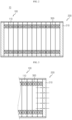
- FIG. 2 is a schematic cross-sectioned view showing a battery module according to the first embodiment of the present disclosure before cell swelling occurs
- FIG. 3 is a schematic cross-sectioned view showing the battery module according to the first embodiment of the present disclosure when cell swelling occurs.
- the first embodiment of the present disclosure is not according to the invention.
- a battery module 10 includes a battery cell stack 100, a casing 200, and an elastic member 300.
- the battery cell stack 100 includes a plurality of battery cells 110 having electrode leads.
- the electrode lead provided at the battery cell 110 is a type of terminal that is exposed to the outside and connected to an external device and may be made of a conductive material.
- the electrode lead may include a positive electrode lead and a negative electrode lead.
- the positive electrode lead and the negative electrode lead may be disposed in opposite directions with respect to the longitudinal direction of the battery cell 110, or the positive electrode lead and the negative electrode lead may be positioned in the same direction with respect to the longitudinal direction of the battery cell 110.
- the electrode lead may be electrically coupled to a bus bar.
- the battery cell 110 may be configured such that a plurality of unit cells arranged in the order of a positive electrode plate, a separator and a negative electrode plate or bi-cells arranged in the order of a positive electrode plate, a separator, a negative electrode plate, a separator, a positive electrode plate, a separator and a negative electrode plate are stacked appropriate for the battery capacity.
- the battery cell stack 100 may be configured such that the plurality of battery cells 110 are stacked on one another.
- the battery cell 110 may have various structures, and the plurality of battery cells 110 may be stacked in various ways.
- the battery cell stack 100 may include a plurality of cartridges (not shown) for accommodating the battery cells 110, respectively.
- Each cartridge (not shown) may be fabricated by injection-molding plastic, and a plurality of cartridges (not shown) having an accommodation portion for accommodating the battery cell 110 may be stacked.
- a cartridge assembly in which a plurality of cartridges (not shown) are stacked may include a connector element or a terminal element.
- the connector element may include various types of electrical connecting components or connecting components for connecting to, for example, a battery management system (BMS) (not shown) capable of providing data on voltage or temperature of the battery cells 110.
- BMS battery management system
- the terminal element includes a positive electrode terminal and a negative electrode terminal as main terminals connected to the battery cell 110, and the terminal element may have a terminal bolt to be electrically connected to the outside.
- the battery cell 110 may have various shapes.
- the casing 200 may accommodate the battery cell stack 100, or the cartridge assembly including the battery cell stack 100.
- the casing 200 entirely surrounds the battery cell stack 100 or the plurality of cartridge assemblies, thereby protecting the battery cell stack 100 or the cartridge assembly from external vibrations or shocks.
- the casing 200 may be formed in a shape corresponding to the battery cell stack 100 or the cartridge assembly. For example, if the battery cell stack 100 or the cartridge assembly has a hexahedral shape, the casing 200 may have a hexahedral shape corresponding thereto.
- the casing 200 may be manufactured, for example, by bending a metal plate, or may be manufactured by plastic injection. In addition, the casing 200 may be manufactured integrally, or may be manufactured separately.
- the casing 200 may have a perforation portion (not shown) through which the connector element or the terminal element, explained above, may be exposed to the outside. That is, the connector element or the terminal element may be electrically connected to a predetermined external component or member, and the penetration portion may be formed in the casing 200 so that the electrical connection is not obstructed by the casing 200.
- the casing 200 may be formed by coupling a plurality of end plates 210.
- the number of the end plates 210 may be variously selected.
- the casing 200 may have a hexahedral structure where six end plates 210 are coupled.
- the casing 200 does not necessarily have to be configured using six end plates 210, and the number of the end plates 210 may be variously selected.
- the shape of the casing 200 is not limited to the hexahedral shape, and the shape of the casing 200 may be variously selected. However, hereinafter, for the sake of convenience of explanation, the following description will be based the case where the casing 200 has a hexahedral shape formed by six end plates 210.
- the elastic member 300 is coupled to an inner side of the casing 200 while avoiding an interference with the battery cell 110 so that a uniform pressure may be formed at the battery cell 110 when swelling occurs at the battery cell 110.
- the elastic member 300 may be provided variously, for example using a plurality of springs.
- the plurality of springs may be coupled to edge portions of the end plates 210 respectively disposed at both ends of the hexahedral casing 200.
- the elastic member 300 may be provided using, for example, four springs and coupled to four edge portions of the end plates 210 at both ends of the casing 200.
- a uniform force may be provided to the battery cells 110 interposed between the end plates 210 at both ends of the casing 200. That is, as described above, referring to FIGS. 1(a) and 1(b) , in the conventional battery cell 2, when swelling occurs at the battery cell 2 occurs, the center portion of the battery cell 2 is inflated more than the edge portion of the battery cell 2, and thus the pressure is distributed non-uniformly at the battery cells when swelling occurs at the battery cells 2, thereby causing a sudden death phenomenon that deteriorates the performance of the battery cells 2 and instantaneously interrupting the electrical connection.
- the springs are respectively coupled to the edge portions of the end plates 210, which correspond to the edge portions of the battery cells 110 to which a larger pressure is applied, compared to the center portion of the battery cells 110, and an elastic force is provided to the edge portions of the end plates 210.
- a uniform pressure distribution may be formed as shown in FIG. 3 , thereby preventing a sudden death phenomenon from occurring at the battery cell 110.
- the elastic member 300 is provided using springs, the spring constant may be appropriately adjusted. Accordingly, the pressure applied to the battery cells 110 may be appropriately adjusted in designing the battery module 10 so that a pressure is applied to the battery cells 110 in a level desired by a user.
- the battery cell stack 100 is accommodated in the casing 200, and the plurality of springs provided in the elastic member 300 are coupled to an inner edge portion of the casing 200.
- the elastic force of the springs is applied to the edge portion of the end plate 210, to which a relatively large pressure is applied in comparison to the center portion of the end plate 210. Accordingly, a uniform pressure distribution may be formed over the entire regions from the edge portions of the end plates 210 to the center portion of the end plates 210.
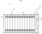
- FIG. 4 is a schematic cross-sectioned view showing a battery module according to the second embodiment of the present disclosure before cell swelling occurs
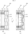
- FIGS. 5(a) and 5(b) are schematic cross-sectioned views showing that a first end plate moves to contact a second end plate when cell swelling occurs at the battery module according to the second embodiment of the present disclosure.
- a first end plate 211 may move to contact a second end plate 212, different from the first embodiment.
- one fixed third end plate 213 is installed at one end of the casing 200, and a first end plate 211 movably provided and a second end plate 212 spaced apart from the first end plate 211 are installed at the other end of the casing 200.
- the first end plate 211 is disposed between the third end plate 213 fixed at one end of the casing 200 and the second end plate 212 to be movable therein, and a plurality of springs are coupled to the first end plate 211 and the third end plate 213, respectively.
- the first end plate 211 is provided to be movable toward the second end plate 212, and when swelling occurs at the battery cell 110, the first end plate 211 may move to contact the second end plate 212.
- a coupling protrusion 215 and a coupling groove 216 which may be engaged with each other, are formed at the first end plate 211 and the second end plate 212, respectively.
- the contact portion between the first end plate 211 and the second end plate 212 may be continuously maintained.
- a uniform pressure distribution is formed over the entire region from the edge portions of the end plate 210 to the center portion of the end plate 210, and also the uniform pressure distribution may be continuously maintained.
- a battery pack (not shown) according to an embodiment of the present disclosure, may include one or more battery modules 10 according to an embodiment of the present disclosure as described above. Also, in addition to the battery modules 10, the battery pack (not shown) may further includes a case for accommodating the battery modules 10, and various devices for controlling charge and discharge of the battery modules 10, such as a BMS, a current sensor, a fuse, and the like.
- a vehicle (not shown) may include the battery module 10 or the battery pack (not shown) described above, and the battery pack (not shown) may include the battery module 10.
- the battery module 10 according to an embodiment of the present disclosure may be applied to the vehicle (not shown), for example, a predetermined vehicle (not shown) provided to use electricity like an electric vehicle or a hybrid electric vehicle.
- the present disclosure is directed to a battery module and a battery pack including the battery module and is particularly applicable to industries associated with a secondary battery.
Landscapes
- Chemical & Material Sciences (AREA)
- Chemical Kinetics & Catalysis (AREA)
- Electrochemistry (AREA)
- General Chemical & Material Sciences (AREA)
- Engineering & Computer Science (AREA)
- Manufacturing & Machinery (AREA)
- Battery Mounting, Suspending (AREA)
Claims (5)
- Module de batterie (1), comprenant :un empilement d'éléments de batterie ayant une pluralité d'éléments de batterie (2) empilés les uns sur les autres ;un boîtier (200) configuré pour encercler l'empilement d'éléments de batterie ; etun organe élastique (300) couplé à un côté interne du boîtier tout en évitant une interférence avec les éléments de batterie de sorte qu'une pression uniforme soit formée au niveau des éléments de batterie lorsqu'un gonflement survient au niveau des éléments de batterie,dans lequel le boîtier est formé par le couplage d'une pluralité de plaques d'extrémité (210) ; etdans lequel l'organe élastique est préparé à l'aide d'une pluralité de ressorts, et la pluralité de ressorts sont couplés à des parties de bord des plaques d'extrémité respectivement disposées des deux côtés du boîtier,dans lequel parmi la pluralité de plaques d'extrémité, une première plaque d'extrémité (211) est disposée entre d'autres plaques d'extrémité pour être mobile dans celles-ci, et la pluralité de ressorts sont couplés à la première plaque d'extrémité dans lequel la première plaque d'extrémité est disposée pour être espacée d'une seconde plaque d'extrémité (212), la seconde plaque d'extrémité est agencée plus loin que la première plaque d'extrémité dans la direction dans laquelle les ressorts sont étendus par un déplacement de la première plaque d'extrémité, et la première plaque d'extrémité et la seconde plaque d'extrémité viennent en contact l'une avec l'autre lorsque la première plaque d'extrémité se déplace.
- Module de batterie selon la revendication 1,
dans lequel le boîtier possède une forme d'hexaèdre où six plaques d'extrémité sont couplées, et l'organe élastique est préparé à l'aide de quatre ressorts de sorte que les ressorts soient couplés à quatre parties de bord des plaques d'extrémité aux deux extrémités du boîtier. - Module de batterie selon la revendication 1,
dans lequel au moins l'une parmi une saillie de couplage (215) et une rainure de couplage (216), qui sont capables d'être mises en prise l'une avec l'autre, est formée au niveau de chacune de la première plaque d'extrémité et de la seconde plaque d'extrémité, respectivement. - Bloc-batterie, comprenant un module de batterie défini selon l'une quelconque des revendications 1 à 3.
- Véhicule, comprenant un module de batterie défini selon l'une quelconque des revendications 1 à 4.
Applications Claiming Priority (2)
| Application Number | Priority Date | Filing Date | Title |
|---|---|---|---|
| KR1020170119764A KR102229410B1 (ko) | 2017-09-18 | 2017-09-18 | 배터리 모듈 및 이를 포함하는 배터리 팩 |
| PCT/KR2018/008090 WO2019054619A1 (fr) | 2017-09-18 | 2018-07-17 | Module de batterie et bloc-batterie le comprenant |
Publications (3)
| Publication Number | Publication Date |
|---|---|
| EP3614453A1 EP3614453A1 (fr) | 2020-02-26 |
| EP3614453A4 EP3614453A4 (fr) | 2020-07-01 |
| EP3614453B1 true EP3614453B1 (fr) | 2023-08-30 |
Family
ID=65723399
Family Applications (1)
| Application Number | Title | Priority Date | Filing Date |
|---|---|---|---|
| EP18855368.9A Active EP3614453B1 (fr) | 2017-09-18 | 2018-07-17 | Module de batterie et bloc-batterie le comprenant |
Country Status (6)
| Country | Link |
|---|---|
| US (1) | US11121395B2 (fr) |
| EP (1) | EP3614453B1 (fr) |
| JP (1) | JP7171584B2 (fr) |
| KR (1) | KR102229410B1 (fr) |
| CN (2) | CN117219942A (fr) |
| WO (1) | WO2019054619A1 (fr) |
Cited By (1)
| Publication number | Priority date | Publication date | Assignee | Title |
|---|---|---|---|---|
| DE102023134486B3 (de) | 2023-12-08 | 2024-12-12 | Energiesachse GmbH | Heimspeicherbatteriezellfixiervorrichtung |
Families Citing this family (31)
| Publication number | Priority date | Publication date | Assignee | Title |
|---|---|---|---|---|
| KR20190126528A (ko) * | 2018-05-02 | 2019-11-12 | 현대자동차주식회사 | 차량용 에너지 저장장치 시스템 |
| CN111834676B (zh) * | 2019-04-18 | 2021-12-24 | 荣盛盟固利新能源科技股份有限公司 | 一种压力可控的软包电池模组 |
| CN209401761U (zh) * | 2019-04-18 | 2019-09-17 | 宁德时代新能源科技股份有限公司 | 电池模块 |
| KR102776217B1 (ko) * | 2019-05-03 | 2025-03-04 | 현대자동차주식회사 | 차량용 배터리 모듈 |
| KR102557414B1 (ko) * | 2019-11-05 | 2023-07-18 | 주식회사 엘지에너지솔루션 | 전지 셀 가압 장치 |
| KR102858414B1 (ko) * | 2019-12-04 | 2025-09-10 | 에스케이온 주식회사 | 셀케이스유닛 및 이를 포함하는 배터리 모듈 |
| US11215519B2 (en) * | 2020-02-20 | 2022-01-04 | Lenovo (Singapore) Pte. Ltd. | Device component swelling detection |
| KR102754508B1 (ko) * | 2020-03-17 | 2025-01-13 | 주식회사 엘지에너지솔루션 | 전지 모듈 및 이를 포함하는 전지 팩 |
| EP3883007A1 (fr) * | 2020-03-20 | 2021-09-22 | Samsung SDI Co., Ltd. | Module de batterie, procédé d'assemblage d'un module de batterie et véhicule incluant un bloc-batterie comprenant au moins un module de batterie |
| DE102020117191B4 (de) | 2020-06-30 | 2025-04-30 | Audi Aktiengesellschaft | Batterie für Kraftfahrzeug sowie Kraftfahrzeug und Herstellverfahren hierzu |
| KR102773545B1 (ko) | 2020-07-20 | 2025-02-27 | 주식회사 엘지에너지솔루션 | 정하중 스프링을 포함하는 전지 모듈 및 이를 포함하는 전지 팩 |
| US11715857B2 (en) * | 2020-07-20 | 2023-08-01 | Aqua Satellite, Inc. | Methods and systems for protecting components of deep water pressure vessels |
| KR102773568B1 (ko) | 2020-07-22 | 2025-02-27 | 주식회사 엘지에너지솔루션 | 전지 모듈, 전지 모듈 시스템 및 전지 모듈을 포함하는 전지 팩 |
| DE202020104503U1 (de) * | 2020-08-04 | 2021-09-07 | Webasto SE | Gehäuse für ein Batteriemodul zur Aufnahme von Batteriezellen |
| KR102922440B1 (ko) * | 2020-09-22 | 2026-02-05 | 주식회사 엘지에너지솔루션 | 전지셀의 수명이 향상된 전지 팩 및 이를 포함하는 디바이스 |
| KR20220039160A (ko) * | 2020-09-22 | 2022-03-29 | 주식회사 엘지에너지솔루션 | 전지셀의 수명이 향상된 전지 팩 및 이를 포함하는 디바이스 |
| KR102917974B1 (ko) * | 2020-10-20 | 2026-01-23 | 주식회사 엘지에너지솔루션 | 배터리 모듈, 이를 포함하는 배터리 팩 및 자동차 |
| US20230282923A1 (en) * | 2020-11-23 | 2023-09-07 | Lg Energy Solution, Ltd. | Battery module, battery pack including battery module, and vehicle including battery pack |
| KR102942726B1 (ko) | 2020-11-23 | 2026-03-20 | 주식회사 엘지에너지솔루션 | 배터리 모듈, 이러한 배터리 모듈을 포함하는 배터리 팩 및 이러한 배터리 팩을 포함하는 자동차 |
| JP7479499B2 (ja) * | 2020-12-11 | 2024-05-08 | 寧徳時代新能源科技股▲分▼有限公司 | 電池、電力消費装置及び電池製造方法 |
| CN112670643B (zh) * | 2020-12-17 | 2022-06-03 | 湖南久森新能源有限公司 | 一种带有防震结构的锂离子电池 |
| KR102834536B1 (ko) * | 2021-01-11 | 2025-07-15 | 주식회사 엘지에너지솔루션 | 팽창완화 유닛을 포함하는 전지 모듈 |
| US20240258593A1 (en) * | 2021-06-18 | 2024-08-01 | HELLA GmbH & Co. KGaA | System and method for measuring lithium-ion state-of-charge |
| KR20230030317A (ko) * | 2021-08-25 | 2023-03-06 | 주식회사 엘지에너지솔루션 | 전지 모듈 및 이를 포함하는 전지 팩 |
| CN114388975B (zh) * | 2021-12-16 | 2023-06-09 | 杭州申昊科技股份有限公司 | 一种用于智能巡检机器人的电池包 |
| CN114865205B (zh) * | 2022-06-02 | 2024-11-05 | 株式会社Aesc日本 | 一种固态电池模组及电池包 |
| FR3143858B1 (fr) * | 2022-12-19 | 2025-06-06 | Renault | Batterie de véhicule avec système de rappel élastique |
| CN116231212B (zh) * | 2023-03-30 | 2025-08-08 | 欣旺达动力科技股份有限公司 | 电池包 |
| WO2024224632A1 (fr) * | 2023-04-28 | 2024-10-31 | 日産自動車株式会社 | Module de batterie |
| KR102618649B1 (ko) | 2023-07-12 | 2023-12-27 | 한광현 | 배터리 셀 적층체에 압력을 가하는 장치를 포함하는배터리 모듈과 이를 구비한 배터리 팩 |
| EP4730454A1 (fr) * | 2023-11-09 | 2026-04-22 | LG Energy Solution, Ltd. | Structure de pression pour batterie au lithium-soufre, et module de batterie et bloc-batterie la comprenant |
Family Cites Families (21)
| Publication number | Priority date | Publication date | Assignee | Title |
|---|---|---|---|---|
| JPH07122252A (ja) * | 1993-10-25 | 1995-05-12 | Sony Corp | 組電池 |
| JP2000048867A (ja) | 1998-07-31 | 2000-02-18 | Toyota Motor Corp | 組電池 |
| JP4127985B2 (ja) | 2001-07-23 | 2008-07-30 | 松下電器産業株式会社 | 電池パック |
| JP2010040295A (ja) * | 2008-08-04 | 2010-02-18 | Toyota Motor Corp | 蓄電装置 |
| JP5270454B2 (ja) | 2009-05-29 | 2013-08-21 | プライムアースEvエナジー株式会社 | 二次電池の分別方法 |
| DE102010012930A1 (de) * | 2010-03-26 | 2011-09-29 | Daimler Ag | Batterie mit einem Stapel von Batterieeinzelzellen |
| US8999557B2 (en) | 2010-04-21 | 2015-04-07 | Samsung Sdi Co., Ltd. | Battery pack with elastic frame |
| JP5537497B2 (ja) | 2011-05-26 | 2014-07-02 | 株式会社日立製作所 | 電池モジュール |
| JP2013026090A (ja) | 2011-07-23 | 2013-02-04 | Toyota Industries Corp | 電池パック |
| JP5880473B2 (ja) * | 2013-02-27 | 2016-03-09 | 株式会社デンソー | 電池ユニット |
| JP2014175078A (ja) * | 2013-03-06 | 2014-09-22 | Captex Co Ltd | 電池パック |
| DE202013003672U1 (de) | 2013-04-10 | 2014-07-11 | Reinz-Dichtungs-Gmbh | Zellstapel |
| CN105981386B (zh) | 2013-12-06 | 2019-02-26 | 华为技术有限公司 | 图像解码装置、图像编码装置及编码数据变换装置 |
| PL3133669T3 (pl) | 2014-10-07 | 2020-04-30 | Lg Chem, Ltd. | Moduł akumulatorowy mający poprawione bezpieczeństwo i czas eksploatacji |
| JP2016085895A (ja) | 2014-10-28 | 2016-05-19 | 株式会社日立製作所 | リチウムイオン二次電池モジュール |
| KR101853526B1 (ko) | 2015-05-12 | 2018-04-30 | 주식회사 엘지화학 | 전지팩 |
| KR101806995B1 (ko) | 2015-05-18 | 2017-12-08 | 주식회사 엘지화학 | 배터리 팩 |
| JP2017004693A (ja) * | 2015-06-08 | 2017-01-05 | 株式会社豊田自動織機 | 電池モジュール及び電池パック |
| DE102016201605A1 (de) * | 2016-02-03 | 2017-08-03 | Robert Bosch Gmbh | Batteriemodul mit einer Mehrzahl an Batteriezellen, Verfahren zu dessen Herstellung und Batterie |
| KR20170119764A (ko) | 2016-04-19 | 2017-10-30 | 에스케이하이닉스 주식회사 | 비교 장치 및 그 동작 방법과 그를 이용한 씨모스 이미지 센서 |
| CN209357789U (zh) | 2019-01-21 | 2019-09-06 | 东莞新能源科技有限公司 | 电池组的固定装置 |
-
2017
- 2017-09-18 KR KR1020170119764A patent/KR102229410B1/ko active Active
-
2018
- 2018-07-17 WO PCT/KR2018/008090 patent/WO2019054619A1/fr not_active Ceased
- 2018-07-17 CN CN202311212669.2A patent/CN117219942A/zh active Pending
- 2018-07-17 JP JP2019541703A patent/JP7171584B2/ja active Active
- 2018-07-17 CN CN201880006586.9A patent/CN110168771A/zh active Pending
- 2018-07-17 US US16/477,693 patent/US11121395B2/en active Active
- 2018-07-17 EP EP18855368.9A patent/EP3614453B1/fr active Active
Cited By (1)
| Publication number | Priority date | Publication date | Assignee | Title |
|---|---|---|---|---|
| DE102023134486B3 (de) | 2023-12-08 | 2024-12-12 | Energiesachse GmbH | Heimspeicherbatteriezellfixiervorrichtung |
Also Published As
| Publication number | Publication date |
|---|---|
| EP3614453A4 (fr) | 2020-07-01 |
| CN110168771A (zh) | 2019-08-23 |
| KR102229410B1 (ko) | 2021-03-17 |
| JP7171584B2 (ja) | 2022-11-15 |
| US11121395B2 (en) | 2021-09-14 |
| CN117219942A (zh) | 2023-12-12 |
| KR20190031831A (ko) | 2019-03-27 |
| JP2020507186A (ja) | 2020-03-05 |
| US20190363392A1 (en) | 2019-11-28 |
| WO2019054619A1 (fr) | 2019-03-21 |
| EP3614453A1 (fr) | 2020-02-26 |
Similar Documents
| Publication | Publication Date | Title |
|---|---|---|
| EP3614453B1 (fr) | Module de batterie et bloc-batterie le comprenant | |
| EP3540817B1 (fr) | Bloc-batterie | |
| KR102301195B1 (ko) | 배터리 팩 | |
| EP3467903B1 (fr) | Bloc batterie | |
| KR102187067B1 (ko) | 배터리 모듈 및 배터리 모듈의 제조 방법 | |
| KR20180055407A (ko) | 배터리 모듈 및 이를 포함하는 배터리 팩 | |
| EP4138190A1 (fr) | Module de batterie, ainsi que bloc-batterie et automobile le comprenant | |
| EP4386958B1 (fr) | Module de batterie, et bloc-batterie et véhicule comprenant celui-ci | |
| EP3285313B1 (fr) | Module de batterie et bloc-batterie le comprenant | |
| US12021212B2 (en) | Battery module, and battery pack and vehicle comprising same | |
| EP3989334A1 (fr) | Module de batterie, et bloc-batterie et véhicule le comprenant | |
| KR20220047057A (ko) | 배터리 모듈, 이를 포함하는 배터리 팩 및 자동차 | |
| EP3514004B1 (fr) | Module de batterie et batterie comprenant celui-ci | |
| EP4199225A1 (fr) | Module de batterie, et bloc-batterie et véhicule le comprenant | |
| EP4258425A1 (fr) | Module de batterie, et bloc-batterie et véhicule le comprenant | |
| KR102714029B1 (ko) | 배터리 모듈, 이를 포함하는 배터리 팩 및 자동차 | |
| KR20220100424A (ko) | 배터리 모듈, 이를 포함하는 배터리 팩 및 자동차 | |
| EP4336639B1 (fr) | Module de batterie, bloc-batterie et véhicule le comprenant | |
| KR20230012355A (ko) | 배터리 팩 및 이를 포함하는 자동차 |
Legal Events
| Date | Code | Title | Description |
|---|---|---|---|
| STAA | Information on the status of an ep patent application or granted ep patent |
Free format text: STATUS: THE INTERNATIONAL PUBLICATION HAS BEEN MADE |
|
| PUAI | Public reference made under article 153(3) epc to a published international application that has entered the european phase |
Free format text: ORIGINAL CODE: 0009012 |
|
| STAA | Information on the status of an ep patent application or granted ep patent |
Free format text: STATUS: REQUEST FOR EXAMINATION WAS MADE |
|
| 17P | Request for examination filed |
Effective date: 20191122 |
|
| AK | Designated contracting states |
Kind code of ref document: A1 Designated state(s): AL AT BE BG CH CY CZ DE DK EE ES FI FR GB GR HR HU IE IS IT LI LT LU LV MC MK MT NL NO PL PT RO RS SE SI SK SM TR |
|
| AX | Request for extension of the european patent |
Extension state: BA ME |
|
| A4 | Supplementary search report drawn up and despatched |
Effective date: 20200529 |
|
| RIC1 | Information provided on ipc code assigned before grant |
Ipc: H01M 2/10 20060101AFI20200525BHEP |
|
| DAV | Request for validation of the european patent (deleted) | ||
| DAX | Request for extension of the european patent (deleted) | ||
| RAP1 | Party data changed (applicant data changed or rights of an application transferred) |
Owner name: LG ENERGY SOLUTION LTD. |
|
| RAP3 | Party data changed (applicant data changed or rights of an application transferred) |
Owner name: LG ENERGY SOLUTION, LTD. |
|
| REG | Reference to a national code |
Ref country code: DE Ref legal event code: R079 Free format text: PREVIOUS MAIN CLASS: H01M0002100000 Ipc: H01M0050209000 Ref country code: DE Ref legal event code: R079 Ref document number: 602018056667 Country of ref document: DE Free format text: PREVIOUS MAIN CLASS: H01M0002100000 Ipc: H01M0050209000 |
|
| GRAP | Despatch of communication of intention to grant a patent |
Free format text: ORIGINAL CODE: EPIDOSNIGR1 |
|
| STAA | Information on the status of an ep patent application or granted ep patent |
Free format text: STATUS: GRANT OF PATENT IS INTENDED |
|
| RIC1 | Information provided on ipc code assigned before grant |
Ipc: H01M 50/242 20210101ALI20230510BHEP Ipc: H01M 50/264 20210101ALI20230510BHEP Ipc: H01M 50/209 20210101AFI20230510BHEP |
|
| INTG | Intention to grant announced |
Effective date: 20230524 |
|
| GRAS | Grant fee paid |
Free format text: ORIGINAL CODE: EPIDOSNIGR3 |
|
| P01 | Opt-out of the competence of the unified patent court (upc) registered |
Effective date: 20230530 |
|
| GRAA | (expected) grant |
Free format text: ORIGINAL CODE: 0009210 |
|
| STAA | Information on the status of an ep patent application or granted ep patent |
Free format text: STATUS: THE PATENT HAS BEEN GRANTED |
|
| AK | Designated contracting states |
Kind code of ref document: B1 Designated state(s): AL AT BE BG CH CY CZ DE DK EE ES FI FR GB GR HR HU IE IS IT LI LT LU LV MC MK MT NL NO PL PT RO RS SE SI SK SM TR |
|
| REG | Reference to a national code |
Ref country code: GB Ref legal event code: FG4D |
|
| REG | Reference to a national code |
Ref country code: CH Ref legal event code: EP |
|
| REG | Reference to a national code |
Ref country code: DE Ref legal event code: R096 Ref document number: 602018056667 Country of ref document: DE |
|
| REG | Reference to a national code |
Ref country code: IE Ref legal event code: FG4D |
|
| REG | Reference to a national code |
Ref country code: LT Ref legal event code: MG9D |
|
| REG | Reference to a national code |
Ref country code: NL Ref legal event code: MP Effective date: 20230830 |
|
| REG | Reference to a national code |
Ref country code: AT Ref legal event code: MK05 Ref document number: 1606614 Country of ref document: AT Kind code of ref document: T Effective date: 20230830 |
|
| PG25 | Lapsed in a contracting state [announced via postgrant information from national office to epo] |
Ref country code: GR Free format text: LAPSE BECAUSE OF FAILURE TO SUBMIT A TRANSLATION OF THE DESCRIPTION OR TO PAY THE FEE WITHIN THE PRESCRIBED TIME-LIMIT Effective date: 20231201 |
|
| PG25 | Lapsed in a contracting state [announced via postgrant information from national office to epo] |
Ref country code: IS Free format text: LAPSE BECAUSE OF FAILURE TO SUBMIT A TRANSLATION OF THE DESCRIPTION OR TO PAY THE FEE WITHIN THE PRESCRIBED TIME-LIMIT Effective date: 20231230 |
|
| PG25 | Lapsed in a contracting state [announced via postgrant information from national office to epo] |
Ref country code: SE Free format text: LAPSE BECAUSE OF FAILURE TO SUBMIT A TRANSLATION OF THE DESCRIPTION OR TO PAY THE FEE WITHIN THE PRESCRIBED TIME-LIMIT Effective date: 20230830 Ref country code: RS Free format text: LAPSE BECAUSE OF FAILURE TO SUBMIT A TRANSLATION OF THE DESCRIPTION OR TO PAY THE FEE WITHIN THE PRESCRIBED TIME-LIMIT Effective date: 20230830 Ref country code: NO Free format text: LAPSE BECAUSE OF FAILURE TO SUBMIT A TRANSLATION OF THE DESCRIPTION OR TO PAY THE FEE WITHIN THE PRESCRIBED TIME-LIMIT Effective date: 20231130 Ref country code: LV Free format text: LAPSE BECAUSE OF FAILURE TO SUBMIT A TRANSLATION OF THE DESCRIPTION OR TO PAY THE FEE WITHIN THE PRESCRIBED TIME-LIMIT Effective date: 20230830 Ref country code: LT Free format text: LAPSE BECAUSE OF FAILURE TO SUBMIT A TRANSLATION OF THE DESCRIPTION OR TO PAY THE FEE WITHIN THE PRESCRIBED TIME-LIMIT Effective date: 20230830 Ref country code: IS Free format text: LAPSE BECAUSE OF FAILURE TO SUBMIT A TRANSLATION OF THE DESCRIPTION OR TO PAY THE FEE WITHIN THE PRESCRIBED TIME-LIMIT Effective date: 20231230 Ref country code: HR Free format text: LAPSE BECAUSE OF FAILURE TO SUBMIT A TRANSLATION OF THE DESCRIPTION OR TO PAY THE FEE WITHIN THE PRESCRIBED TIME-LIMIT Effective date: 20230830 Ref country code: GR Free format text: LAPSE BECAUSE OF FAILURE TO SUBMIT A TRANSLATION OF THE DESCRIPTION OR TO PAY THE FEE WITHIN THE PRESCRIBED TIME-LIMIT Effective date: 20231201 Ref country code: FI Free format text: LAPSE BECAUSE OF FAILURE TO SUBMIT A TRANSLATION OF THE DESCRIPTION OR TO PAY THE FEE WITHIN THE PRESCRIBED TIME-LIMIT Effective date: 20230830 Ref country code: AT Free format text: LAPSE BECAUSE OF FAILURE TO SUBMIT A TRANSLATION OF THE DESCRIPTION OR TO PAY THE FEE WITHIN THE PRESCRIBED TIME-LIMIT Effective date: 20230830 |
|
| PG25 | Lapsed in a contracting state [announced via postgrant information from national office to epo] |
Ref country code: PL Free format text: LAPSE BECAUSE OF FAILURE TO SUBMIT A TRANSLATION OF THE DESCRIPTION OR TO PAY THE FEE WITHIN THE PRESCRIBED TIME-LIMIT Effective date: 20230830 Ref country code: NL Free format text: LAPSE BECAUSE OF FAILURE TO SUBMIT A TRANSLATION OF THE DESCRIPTION OR TO PAY THE FEE WITHIN THE PRESCRIBED TIME-LIMIT Effective date: 20230830 |
|
| PG25 | Lapsed in a contracting state [announced via postgrant information from national office to epo] |
Ref country code: ES Free format text: LAPSE BECAUSE OF FAILURE TO SUBMIT A TRANSLATION OF THE DESCRIPTION OR TO PAY THE FEE WITHIN THE PRESCRIBED TIME-LIMIT Effective date: 20230830 |
|
| PG25 | Lapsed in a contracting state [announced via postgrant information from national office to epo] |
Ref country code: SM Free format text: LAPSE BECAUSE OF FAILURE TO SUBMIT A TRANSLATION OF THE DESCRIPTION OR TO PAY THE FEE WITHIN THE PRESCRIBED TIME-LIMIT Effective date: 20230830 Ref country code: RO Free format text: LAPSE BECAUSE OF FAILURE TO SUBMIT A TRANSLATION OF THE DESCRIPTION OR TO PAY THE FEE WITHIN THE PRESCRIBED TIME-LIMIT Effective date: 20230830 Ref country code: ES Free format text: LAPSE BECAUSE OF FAILURE TO SUBMIT A TRANSLATION OF THE DESCRIPTION OR TO PAY THE FEE WITHIN THE PRESCRIBED TIME-LIMIT Effective date: 20230830 Ref country code: EE Free format text: LAPSE BECAUSE OF FAILURE TO SUBMIT A TRANSLATION OF THE DESCRIPTION OR TO PAY THE FEE WITHIN THE PRESCRIBED TIME-LIMIT Effective date: 20230830 Ref country code: DK Free format text: LAPSE BECAUSE OF FAILURE TO SUBMIT A TRANSLATION OF THE DESCRIPTION OR TO PAY THE FEE WITHIN THE PRESCRIBED TIME-LIMIT Effective date: 20230830 Ref country code: CZ Free format text: LAPSE BECAUSE OF FAILURE TO SUBMIT A TRANSLATION OF THE DESCRIPTION OR TO PAY THE FEE WITHIN THE PRESCRIBED TIME-LIMIT Effective date: 20230830 Ref country code: SK Free format text: LAPSE BECAUSE OF FAILURE TO SUBMIT A TRANSLATION OF THE DESCRIPTION OR TO PAY THE FEE WITHIN THE PRESCRIBED TIME-LIMIT Effective date: 20230830 Ref country code: PT Free format text: LAPSE BECAUSE OF FAILURE TO SUBMIT A TRANSLATION OF THE DESCRIPTION OR TO PAY THE FEE WITHIN THE PRESCRIBED TIME-LIMIT Effective date: 20240102 |
|
| PG25 | Lapsed in a contracting state [announced via postgrant information from national office to epo] |
Ref country code: IT Free format text: LAPSE BECAUSE OF FAILURE TO SUBMIT A TRANSLATION OF THE DESCRIPTION OR TO PAY THE FEE WITHIN THE PRESCRIBED TIME-LIMIT Effective date: 20230830 |
|
| REG | Reference to a national code |
Ref country code: DE Ref legal event code: R097 Ref document number: 602018056667 Country of ref document: DE |
|
| PLBE | No opposition filed within time limit |
Free format text: ORIGINAL CODE: 0009261 |
|
| STAA | Information on the status of an ep patent application or granted ep patent |
Free format text: STATUS: NO OPPOSITION FILED WITHIN TIME LIMIT |
|
| PG25 | Lapsed in a contracting state [announced via postgrant information from national office to epo] |
Ref country code: SI Free format text: LAPSE BECAUSE OF FAILURE TO SUBMIT A TRANSLATION OF THE DESCRIPTION OR TO PAY THE FEE WITHIN THE PRESCRIBED TIME-LIMIT Effective date: 20230830 |
|
| 26N | No opposition filed |
Effective date: 20240603 |
|
| PG25 | Lapsed in a contracting state [announced via postgrant information from national office to epo] |
Ref country code: BG Free format text: LAPSE BECAUSE OF FAILURE TO SUBMIT A TRANSLATION OF THE DESCRIPTION OR TO PAY THE FEE WITHIN THE PRESCRIBED TIME-LIMIT Effective date: 20230830 |
|
| PG25 | Lapsed in a contracting state [announced via postgrant information from national office to epo] |
Ref country code: BG Free format text: LAPSE BECAUSE OF FAILURE TO SUBMIT A TRANSLATION OF THE DESCRIPTION OR TO PAY THE FEE WITHIN THE PRESCRIBED TIME-LIMIT Effective date: 20230830 |
|
| PG25 | Lapsed in a contracting state [announced via postgrant information from national office to epo] |
Ref country code: MC Free format text: LAPSE BECAUSE OF FAILURE TO SUBMIT A TRANSLATION OF THE DESCRIPTION OR TO PAY THE FEE WITHIN THE PRESCRIBED TIME-LIMIT Effective date: 20230830 |
|
| REG | Reference to a national code |
Ref country code: CH Ref legal event code: PL |
|
| PG25 | Lapsed in a contracting state [announced via postgrant information from national office to epo] |
Ref country code: LU Free format text: LAPSE BECAUSE OF NON-PAYMENT OF DUE FEES Effective date: 20240717 |
|
| PG25 | Lapsed in a contracting state [announced via postgrant information from national office to epo] |
Ref country code: LU Free format text: LAPSE BECAUSE OF NON-PAYMENT OF DUE FEES Effective date: 20240717 |
|
| PG25 | Lapsed in a contracting state [announced via postgrant information from national office to epo] |
Ref country code: CH Free format text: LAPSE BECAUSE OF NON-PAYMENT OF DUE FEES Effective date: 20240731 Ref country code: BE Free format text: LAPSE BECAUSE OF NON-PAYMENT OF DUE FEES Effective date: 20240731 |
|
| REG | Reference to a national code |
Ref country code: BE Ref legal event code: MM Effective date: 20240731 |
|
| PGFP | Annual fee paid to national office [announced via postgrant information from national office to epo] |
Ref country code: GB Payment date: 20250624 Year of fee payment: 8 |
|
| PGFP | Annual fee paid to national office [announced via postgrant information from national office to epo] |
Ref country code: FR Payment date: 20250624 Year of fee payment: 8 |
|
| PG25 | Lapsed in a contracting state [announced via postgrant information from national office to epo] |
Ref country code: IE Free format text: LAPSE BECAUSE OF NON-PAYMENT OF DUE FEES Effective date: 20240717 |
|
| PGFP | Annual fee paid to national office [announced via postgrant information from national office to epo] |
Ref country code: DE Payment date: 20250624 Year of fee payment: 8 |
|
| PG25 | Lapsed in a contracting state [announced via postgrant information from national office to epo] |
Ref country code: CY Free format text: LAPSE BECAUSE OF FAILURE TO SUBMIT A TRANSLATION OF THE DESCRIPTION OR TO PAY THE FEE WITHIN THE PRESCRIBED TIME-LIMIT; INVALID AB INITIO Effective date: 20180717 |
|
| PG25 | Lapsed in a contracting state [announced via postgrant information from national office to epo] |
Ref country code: HU Free format text: LAPSE BECAUSE OF FAILURE TO SUBMIT A TRANSLATION OF THE DESCRIPTION OR TO PAY THE FEE WITHIN THE PRESCRIBED TIME-LIMIT; INVALID AB INITIO Effective date: 20180717 |