EP3614507A1 - Pinces à presser ou à sertir - Google Patents
Pinces à presser ou à sertir Download PDFInfo
- Publication number
- EP3614507A1 EP3614507A1 EP18190465.7A EP18190465A EP3614507A1 EP 3614507 A1 EP3614507 A1 EP 3614507A1 EP 18190465 A EP18190465 A EP 18190465A EP 3614507 A1 EP3614507 A1 EP 3614507A1
- Authority
- EP
- European Patent Office
- Prior art keywords
- pliers
- movable
- lever
- hand lever
- crimping
- Prior art date
- Legal status (The legal status is an assumption and is not a legal conclusion. Google has not performed a legal analysis and makes no representation as to the accuracy of the status listed.)
- Granted
Links
Images






Classifications
-
- B—PERFORMING OPERATIONS; TRANSPORTING
- B25—HAND TOOLS; PORTABLE POWER-DRIVEN TOOLS; MANIPULATORS
- B25B—TOOLS OR BENCH DEVICES NOT OTHERWISE PROVIDED FOR, FOR FASTENING, CONNECTING, DISENGAGING, OR HOLDING
- B25B7/00—Pliers; Other hand-held gripping tools with jaws on pivoted limbs; Details applicable generally to pivoted-limb hand tools
-
- B—PERFORMING OPERATIONS; TRANSPORTING
- B25—HAND TOOLS; PORTABLE POWER-DRIVEN TOOLS; MANIPULATORS
- B25B—TOOLS OR BENCH DEVICES NOT OTHERWISE PROVIDED FOR, FOR FASTENING, CONNECTING, DISENGAGING, OR HOLDING
- B25B27/00—Hand tools, specially adapted for fitting together or separating parts or objects whether or not involving some deformation, not otherwise provided for
- B25B27/14—Hand tools, specially adapted for fitting together or separating parts or objects whether or not involving some deformation, not otherwise provided for for assembling objects other than by press fit or detaching same
- B25B27/146—Clip clamping hand tools
-
- B—PERFORMING OPERATIONS; TRANSPORTING
- B25—HAND TOOLS; PORTABLE POWER-DRIVEN TOOLS; MANIPULATORS
- B25B—TOOLS OR BENCH DEVICES NOT OTHERWISE PROVIDED FOR, FOR FASTENING, CONNECTING, DISENGAGING, OR HOLDING
- B25B7/00—Pliers; Other hand-held gripping tools with jaws on pivoted limbs; Details applicable generally to pivoted-limb hand tools
- B25B7/12—Pliers; Other hand-held gripping tools with jaws on pivoted limbs; Details applicable generally to pivoted-limb hand tools involving special transmission means between the handles and the jaws, e.g. toggle levers, gears
- B25B7/123—Pliers; Other hand-held gripping tools with jaws on pivoted limbs; Details applicable generally to pivoted-limb hand tools involving special transmission means between the handles and the jaws, e.g. toggle levers, gears with self-locking toggle levers
-
- B—PERFORMING OPERATIONS; TRANSPORTING
- B25—HAND TOOLS; PORTABLE POWER-DRIVEN TOOLS; MANIPULATORS
- B25B—TOOLS OR BENCH DEVICES NOT OTHERWISE PROVIDED FOR, FOR FASTENING, CONNECTING, DISENGAGING, OR HOLDING
- B25B7/00—Pliers; Other hand-held gripping tools with jaws on pivoted limbs; Details applicable generally to pivoted-limb hand tools
- B25B7/14—Locking means
-
- H—ELECTRICITY
- H01—ELECTRIC ELEMENTS
- H01R—ELECTRICALLY-CONDUCTIVE CONNECTIONS; STRUCTURAL ASSOCIATIONS OF A PLURALITY OF MUTUALLY-INSULATED ELECTRICAL CONNECTING ELEMENTS; COUPLING DEVICES; CURRENT COLLECTORS
- H01R43/00—Apparatus or processes specially adapted for manufacturing, assembling, maintaining, or repairing of line connectors or current collectors or for joining electric conductors
- H01R43/04—Apparatus or processes specially adapted for manufacturing, assembling, maintaining, or repairing of line connectors or current collectors or for joining electric conductors for forming connections by deformation, e.g. crimping tool
- H01R43/042—Hand tools for crimping
Definitions
- the present invention relates to a pressing or crimping tool.
- a pressing or crimping tool can be used to crimp or crimp a workpiece using a manual actuation of hand levers.
- a generic pressing pliers preferably of the mechanical fluid-tight connection in the fluid technology, for example, for connecting pipes with each other or with fluidic connectors.
- the pliers are used to plastically deform the pipes to be connected or a so-called fitting that ensures the mechanical connection and the fluid-tight seal.
- Exemplary embodiments of a generic pressing tongs can be found in the documents DE 197 09 639 A1 . DE 198 34 859 C2 . DE 199 24 086 C2 . DE 199 24 087 C2 . DE 199 63 097 C1 . DE 103 46 241 B3 . EP 2 995 424 A1 be removed.
- DE 10 2007 001 235 B4 discloses a non-generic pressing pliers, in which the pliers jaws are pivotally coupled to one another via a swivel joint.
- a first hand lever is articulated on the swivel joint.
- a second hand lever is articulated with a cranked end region on a first jaw.
- a third hand lever is arranged in an open position of the jaws between the first hand lever and the second hand lever.
- the third hand lever is articulated in a cranked end area on a pendulum support, the other end area of which is articulated on a second jaw.
- the first hand lever and the third hand lever are coupled to one another via a respective pivotally articulated pressure lever, a pivot pin for coupling the pressure lever to the third hand lever being fixed to the first hand lever.
- the three hand levers can use different toggle lever drives in two successive partial closing strokes, optimized for the respective partial closing strokes with regard to the forces and pivoting as follows: In a first partial closing stroke, the third hand lever is pivoted in the direction of the first hand lever. In this case, the joint between the end region of the third hand lever and the pendulum support forms a knee joint of the first toggle lever drive thus formed.
- the first hand lever and the third hand lever are oriented parallel to one another and the first toggle lever drive as well as the first hand lever and the third hand lever are fixed by the user's hands enclosing the two hand levers or by a suitable switching device.
- the second hand lever is pivoted in the direction of the first and third hand levers.
- a second toggle lever drive engages the other jaw.
- one toggle lever is formed by the pressure lever, while the other toggle lever is formed by the cranked end region of the second hand lever and the knee joint is formed by the pivot bearing between the pressure lever and the second hand lever.
- the three hand levers thus serve to ensure different partial closing strokes of the pliers jaws with different closing movements of a sub-combination of the three hand levers.
- the invention relates to pressing or crimping pliers of basically any type (cf. also the prior art mentioned at the beginning), provided that it has a fixed pliers part with a fixed hand lever and a fixed pliers jaw.
- the fixed pliers part can be made in one or more parts.
- the pressing or crimping pliers according to the invention have a movable hand lever.
- the movable hand lever is coupled to a movable jaw by a drive mechanism.
- the drive mechanism can be designed as any gear connection with a suitable step-up or step-down of the forces and paths.
- the coupling of the movable hand lever via the drive mechanism to the movable pliers jaw is such that a closing movement of the movable pliers jaw can be brought about by pivoting the movable hand lever in the direction of the fixed hand lever. With this closing movement of the movable pliers jaw, a workpiece is crimped or pressed between the fixed one Pliers jaw and the movable pliers jaw, in particular in the area of dies held or formed by the pliers jaws.
- the invention proposes to equip the pressing or crimping pliers (in addition to the fixed hand lever and the movable hand lever) with a further lever.
- the other lever is coupled to the movable jaw by a drive connection.
- the coupling via the drive connection is such that an opening movement of the pliers jaws into an insertion and / or removal position can be brought about by pivoting the further lever.
- the movement of the further lever is permanently coupled to the movement of the movable hand lever, so that the movable hand lever and the further lever, when one of the two levers is actuated, have the same pivoting or different pivoting with a fixed or structural design experienced predetermined varying gear ratio.
- the movement of the further lever it is also possible for the movement of the further lever to be decoupled from the movement of the movable hand lever over a partial stroke or over the entire stroke, so that it is possible to pivot the further lever while the movable hand lever is not also pivoted (and / or the other way around).
- the different levers provided can be used for different purposes within the scope of the invention: While crimping or pressing of a workpiece can be brought about by a closing movement of the pliers jaws as a result of manual actuation of the movable hand lever, the manual actuation of the further lever can be used to: bring about an opening movement of the pliers jaw in an insertion and / or removal position in which the insertion and / or removal of a workpiece is made possible or simplified.
- the further lever is preferably arranged in the grip area of a hand, which encloses the fixed hand lever and / or the movable hand lever, or a finger of this hand, so that, for example, on the one hand, without any reaching around or with minimal effort the actuation of the movable hand lever for bringing about the closing movement of the pliers jaws for crimping or crimping a workpiece can be brought about and, on the other hand, by actuating the further lever, the opening movement of the pliers jaws can be brought into the insertion and / or removal position.
- the further lever can have any shape (for example straight or cranked), have any length and / or be arranged at any point on the pressing or crimping pliers.
- the further lever is an additional hand lever which is arranged between the fixed hand lever and the movable hand lever. This configuration uses an intermediate space that is present anyway between the fixed hand lever and the movable hand lever for the arrangement of the additional hand lever. In this case, the additional hand lever and the movable hand lever are pivoted in the same swivel plane.
- the end region of the additional hand lever facing away from the pliers head of the pressing or crimping pliers lies in the region of the swiveling circle of the corresponding end region of the movable hand lever or lies outside or within the same.
- the actuation kinematics for the actuation of the additional hand lever and the transmission of the movement of the additional hand lever to the movable jaw can be any.
- the additional hand lever is coupled to the movable pliers jaw via the drive connection such that an opening movement of the pliers jaws can be brought about by pivoting the additional hand lever in the direction of the fixed hand lever.
- the user takes his fingers off the additional hand lever and places them on the movable hand lever from the outside, while the inner surface of the hand is still supported on the outside from the fixed hand lever can. The user can then use their fingers to do the necessary Apply forces to the movable hand lever to bring about the closing movement of the pliers jaws for crimping or pressing a workpiece.
- the drive connection via which the additional hand lever is coupled to the movable pliers jaw, can be designed as any gear connection with a step-up or step-down.
- the drive connection is a fixed connection of the additional hand lever with the movable pliers jaw.
- the additional hand lever is designed as an integral component with the movable pliers jaw or the additional hand lever and the movable pliers jaw are configured as separate components that are directly or indirectly and detachably or non-detachably, but in any case with a fixed connection are connected. In this way, a structurally simple but reliable drive connection can be provided.
- the pressing or crimping pliers have an opening spring.
- the opening spring acts on the movable pliers jaw and / or the movable hand lever (directly or indirectly) in such a way that the movable pliers jaw and / or the movable hand lever are / are automatically moved from a closed position to an opening direction. This is particularly advantageous when the pressing or crimping pliers have reached the closed position in which the workpiece is completely crimped or pressed.
- the opening spring can then be used to automatically open the movable jaw and / or the movable hand lever when the manual forces applied to the fixed hand lever and the movable hand lever are reduced or eliminated, which increases the ease of use of the pressing or crimping pliers.
- the pressing or crimping pliers have a closing spring.
- the closing spring acts on the movable jaw and / or the further lever in such a way that the movable jaw is acted upon in the closing direction and / or the further lever is automatically moved from a closed position towards an open position.
- a closing spring force generated by the closing spring and acting on the moving jaw in the closing direction can be used, for example, to act upon the other after the insertion and / or removal position has been brought about by actuating the further lever and inserting the workpiece into the dies Lever is reduced or eliminated by the user, while then the closing spring force acts on the movable jaw in the closing direction.
- the workpiece between the two jaws with the Closing spring force clamped with which this can be fixed in the position and / or orientation previously brought about manually between the dies.
- the workpiece, which is fixed in the dies between the jaws it is also possible for the workpiece, which is fixed in the dies between the jaws, to be readjusted by the user pushing the workpiece into a different orientation and / or position, which then causes the jaws to spring open against the action the closing spring leads or a frictional sliding movement of the workpiece relative to the dies acted upon by the closing spring.
- an opening spring and / or a closing spring can be formed by a single spring or also a plurality of springs, which can then be arranged in parallel or in series.
- the at least one spring can be made of any material (for example metal, plastic, elastomer material, composite material). It can be a compression spring, a tension spring, a torsion spring, a torsion spring or a spring of any other type.
- the at least one spring can be integrated at any point in the force flow of the pressing or crimping pliers. At least one spring with a linear or a non-linear spring characteristic can be used.
- the closing spring is articulated with a spring base on the fixed pliers part, while it is articulated with the other spring base on the movable pliers part.
- the opening spring is articulated with a spring base on the fixed pliers part, while it is articulated with the other spring base on the movable hand lever.
- the invention also includes embodiments in which the opening spring and the closing spring are formed by a single integral spring element, cf. especially the unpublished European patent application with the file number EP 18 166 729.6 ,
- the invention includes embodiments in which the drive mechanism for coupling the movable hand lever to the movable pliers jaw is permanently effective, so that the movable hand lever is also moved when the movable pliers jaw is moved by the further lever as a result of the coupling via the drive mechanism.
- the drive mechanism via which the movable hand lever is coupled to the movable pliers jaw, has a game. The game is limited by a stop.
- a drive element of the drive mechanism rests against the stop, with which the game is not effective and a play-free transfer of the pressing or crimping force can take place.
- the further lever is pivoted with an opening movement of the pliers jaws into the insertion and / or removal position, the drive element moves away from the stop, so that a movement takes place using the play.
- the movable hand lever is not moved in spite of the opening movement of the pliers jaws for the opening movement to bring about the insertion and / or removal position by actuating the further lever, which may simplify the operation of the pressing or crimping pliers.
- the game can be of any size, so that the explained effect occurs only for a partial movement or the explained entire movement.
- the game is at least so large that in an open position of the moving hand lever depending on the position of the further lever and caused by this, the movable jaw of the pliers from the closed position can be moved into the open position without the movable hand lever being in its open position leaves. In this way it can be ensured that there is no change in the pivoting angle of the movable hand lever during the entire actuation of the further lever.
- the opening spring does not exert any opening spring force on the movable pliers jaw in an open position of the movable hand lever, with the result that the closing spring force of the closing spring is not reduced by the action of the opening spring.
- the closing spring exerts a closing spring force on the movable jaw. This closing spring force is minimal in a closed position of the further lever, while this is maximum in an open position of the further lever.
- the closing spring can be relaxed in the closed position of the further lever, so that the minimum closing spring force is zero.
- the closing spring force is already greater than zero, which means that it is always preloaded.
- the closing spring can ensure, for example, that even when a small workpiece is inserted into the dies formed or carried by the pliers jaws, the workpiece is secured between the dies with sufficient closing spring force.
- the use of a so-called positioner or locator can be dispensed with by holding the workpiece by means of the closing spring force of the closing spring in order to ensure the correct position or orientation of the workpiece relative to the dies.
- the drive mechanism has an elongated hole which provides the play.
- the stop is formed by an end region of the elongated hole.
- any drive mechanism can be used in the crimping or crimping pliers.
- the drive mechanism is preferably a toggle lever drive.
- the toggle lever drive has a pivot pin, which can be a pivot pin of a joint for a toggle lever or also a pivot pin for forming the knee joint.
- the pivot pin can be received in an elongated hole, with which the required play and the stop can be provided.
- the crimping or crimping pliers it is proposed that it have a positive locking. Forced locking is used to secure a once reached closed position of the pliers jaws during crimping or pressing the workpiece, so that the pliers jaws do not open undesirably if the operating force is temporarily reduced by the user or the hand is removed from the press during the press or crimp stroke - or crimping tool is used. On the other hand, the forced locking should enable the pressing or crimping pliers to reopen when a closed position is reached.
- the effect and the design of the forced locking mechanism can be specifically adapted to the requirements here as follows:
- the forced locking mechanism does not secure the position of the movable jaw over the entire possible range of motion of the movable jaw. Rather, the positive lock does not block a movement of the movable pliers jaw caused by the further lever, while the forced lock blocks a movement of the movable pliers jaw caused by the movable hand lever.
- the compulsory lock will not take effect if the Removal and / or insertion position is to be brought about by actuation of the further lever, so that an opening movement is possible, while the positive lock is intended to enable the closing movement for crimping or pressing a workpiece, while at the same time securing a closing position achieved in the process.
- the actual pressing or crimping stroke is then carried out by the user when the movable hand lever is actuated, which (possibly after a certain idle stroke) runs from the starting position to the closed position.
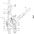
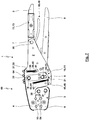
- the illustrated embodiment of a crimping pliers 1 has a fixed pliers part 2 and a movable pliers part 3.
- the fixed pliers part 2 has a fixed pliers jaw 4 and a fixed hand lever 5, which are firmly connected to one another.
- the movable pliers part 3 has a movable pliers jaw 6.
- the fixed pliers part 2 and the movable pliers part 3 are pivotally connected to one another via a pivot bearing 7.
- a movable hand lever 9 is articulated on the fixed pliers part 2 via a pivot bearing 8.
- the movable hand lever 9 is coupled to the movable pliers part 3 via a drive mechanism 10 in such a way that by means of a manual pivoting of the movable hand lever 9 relative to the fixed hand lever 5, the movable pliers part 3 and thus the movable pliers jaw 6 relative to the fixed pliers jaw 4 can be brought about.
- the pliers jaws 4, 6 directly form dies for pressing or crimping a workpiece.
- the pliers jaws 4, 6 carry dies by suitable receptacles, the receptacles and dies corresponding to the patent specification US 6,053,025 A , the disclosure of which is made the subject of the present patent application.
- the drive mechanism 10 is designed as a toggle lever drive 11.
- the toggle lever drive 11 has a toggle lever 13 designed as a pressure lever 12, while the other toggle lever 14 is formed by a cranked end region of the movable hand lever 9.
- the two toggle levers 13, 14 are pivotally connected to one another via a knee joint 15.
- the toggle lever 14 is from the cranked material area of the movable hand lever 9 between the Swivel bearing 8 and the knee joint 15 are formed.
- the end region of the toggle lever 13 facing away from the knee joint 15 is articulated on the movable tong part 3 via a pivot bearing 16.
- the toggle levers 13, 14 form a knee angle in the storage position 55, which is in the range from 90 ° to 120 °.
- the knee angle can be increased, the knee angle in the closed position being, for example, between 170 ° and 180 °, so that with the closing movement the knee angle approximates the extended position with the associated large position Power development of the toggle lever drive 11.
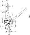
- Fig. 3 shows the crimping pliers 1 without actuating forces applied by the user and without a workpiece inserted in dies 53, 54.
- the closing spring 36 As a result of the action of the closing spring 36, the movable pliers part with the movable pliers jaw 6 or their dies 53, 53 is in the closed position, so that the pliers mouth is open. This closed position correlates with an open position of the additional hand lever 49.
- the closing spring 36 is located in the Condition of minimal closing spring force. In the closed position, the closing spring force can be zero or it can already be greater than zero.
- the closed position of the jaws 4, 6 would correlate with the closed position of the movable hand lever 9.
- the opening spring 42 can move the movable hand lever 9 into the open position.
- the opening spring 42 also has a minimal opening spring force acting in the opening direction.
- the operating position according to Fig. 3 can also be referred to as stock position 55.
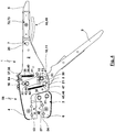
- From stock position 55 according to Fig. 3 can be an insertion and / or removal position 56 according to Fig. 4 be brought about.
- the additional hand lever 49 is pivoted manually from its open position in accordance with Fig. 3 in its closed position Fig. 4 , This goes hand in hand with a corresponding pivoting of the movable pliers part 3, with which this and the movable pliers jaw 6 assume the opening position, namely the insertion and / or removal position 56.
- the movable hand lever 9 can remain in its open position.
- the pivot pin 23 slides along the elongated hole 51. With the pivoting of the additional hand lever 49, the closing spring force of the closing spring 36 is increased.
- a workpiece 57 can be inserted into the jaws of the pliers and between the dies 53, 54 in the insertion and / or removal position 56 thus produced.
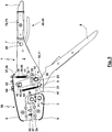
- the action of the closing spring 36 causes the additional hand lever 49 to move automatically in the opening direction, which is accompanied by a closing movement of the movable pliers part 3.
- This closing movement takes place until a stop position 58 according to Fig. 5 is reached.
- the closing spring force exerted by the closing spring 36 on the movable tong part 3 is supported in that the workpiece is clamped between the tong jaws 4, 6 or between the dies 53, 54.
- This clamping due to the closing spring force leads to a securing of the position and / or orientation of the workpiece 57 with respect to the dies 53, 54.
- the closing spring force of the closing spring 36 has decreased, which also occurs when using a small workpiece 57 as a result of Design of the closing spring 36 is still large enough to ensure the maintenance of the position and / or orientation of the workpiece 57.
- the opening spring force of the opening spring 42 remains unchanged.
- the pivot pin 23 has moved a partial path along the elongated hole 51, the pivot pin 23 being arranged at a distance from the stop 52 of the elongated hole 51. The remaining distance of the pivot pin 23 from the stop 52 depends on the size of the workpiece 57 in the unpressed or uncrimped state.
- the closing spring 36 is reduced.
- the closing position 7 is reached, the workpiece 57 is completely between the dies 53, 54 pressed or crimped. If the hand forces applied by the user are then eliminated, the closed position of the pliers jaws 4, 6 and the open position of the additional hand lever 49 are maintained as a result of the action of the closing spring 36, so that the closing spring force generated by the closing spring 36 also ensures that the crimped workpiece 57 is clamped between the jaws 4, 6, here between the dies 53, 54 and cannot fall out of the dies 53, 54.
- the effect of the opening spring 42 leads to a pivoting of the hand lever 9 from the closed position according to Fig. 7 in the open position according to Fig. 8 he follows.
- the play 50 of the drive mechanism 10 is used during this movement. For the illustrated embodiment, this means that the pivot pin 23 moves away from the stop 52.
- the additional hand lever 49 can be used to transfer the movable pliers part 3 and the movable pliers jaw 6 into the insertion and / or removal position 56 (cf. Fig. 9 ).
- an intermediate space formed between plates of the crimping pliers 1, here fixed pliers partial plates 17 and / or movable pliers partial plates 18, is closed or sealed from the outside by a covering 61, for example made of plastic.
- the cover 61 is roughly T-shaped with a web 62 formed by a vertical leg. In the region of the web 62, the cover 61 is fastened with the movable pliers part 3, which is done here by means of the fastening bolts 30, 31 he follows.
- a corresponding cladding 63 extends in the area of the outer end faces of the fixed pliers partial plates 17.
- the cladding 63 has outer fastening eyelets 64, the function of which will be described below.
- the crimping pliers 1 only have a mechanical pliers part 65.
- the Crimping tool 1 according to Fig. 10 in addition to the mechanical pliers part 65 via an electronic assembly 66.
- the configuration of the electronic assembly 66, its functions, its coupling with the mechanical pliers part 65 and / or its energy supply and its wireless or wired communication can / may be according to the not previously published European patent application with the official file number EP 18 173 803.0 be trained, which is made the subject of the present patent application in this regard.
- the electronic assembly 66 has a housing which is formed with two half-shell-like housing parts 67, 68, wherein a transparent cover disk 69 can also be arranged in a housing part 67, 68 to form a viewing window for a display or display 70.
- a circuit board 71 is arranged in an intermediate space arranged between the housing, here a housing part 67 and the mechanical pliers part 65.
- the housing parts 67, 68 are latched, locked or pressed together and with the fastening eyelets 64 via suitable connecting pins and receptacles.
- the electronic assembly 66 can have a holder 72 with a battery or a rechargeable accumulator 73.
- the holder 72 is held on the fixed pliers part 2, here in the area of the fixed hand lever part 19, which is already in the 1 to 9 has been shown, although this is not necessary here for the purely mechanical design of the crimping tool 1. It is possible for a handle 74 to be pushed onto the fixed hand lever part 19, in the interior of which the holder 72 with the battery 73 is then received.
- the handle 74 can then be fixed to the fixed pliers part 2, here the fixed hand lever part 19, which can also be done by a latching and / or locking connection, for example with a detachable connection, by pressing a push button to unlatch the handle 74 can, which can for example be arranged on the inner side facing the other hand lever 9.
- the removal of the handle 74 can be used for an exchange of a battery or an accumulator 73.
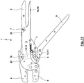
- Fig. 11 and 12 show an embodiment of a crimping tool 1 which, apart from the differences mentioned below, essentially corresponds to the embodiment of the crimping tool 1 1 to 9 equivalent.
- the pressure lever 12 does not have an elongated hole 51, so that the drive mechanism 10 also has no play 50. This means that with the Actuation of the additional hand lever 49 for the purpose of transferring the movable pliers jaw 6 into the insertion and / or removal position 56 also causes the movable hand lever 9 to be pivoted (further) in the opening direction.
- the illustrated embodiment also includes the closing spring 36 and the opening spring 42 and integrated in the crimping pliers 1:
- the closing spring 36 and the opening spring 42 are designed here as an integral spring device 75, which is a U-shaped spiral spring 76, which is two elastic interconnected side legs 77, 78.
- the side leg 77 is supported in its free end region on a support 79 which is formed or held by the movable pliers part 3. In this end region, the side leg 77 is additionally supported on a support 80 which is formed or supported by the fixed pliers part 2.
- the other side leg 78 is supported in an end region on a support 81 which is formed or held by the movable pliers part 3.
- the side leg 78 is supported on a support 82 which is formed or supported by the fixed pliers part 2.
- the functioning of the crimping tool 1 is as follows: In Fig. 12 the spring device 75 is supported between the two supports 80, 82 on the fixed pliers part 2 and thus caught. It is therefore a stable equilibrium. An actuation of the additional hand lever 49 causes the support 79 to take the side leg 77 with it, while the side leg 78 is still supported on the support 82. The spring device 75 is thus compressed and generates a closing spring force. During this movement caused by the additional hand lever 49, the side leg 77 detaches from the support 80 and the side leg 78 from the support 81.
- one of the spring devices 75 thus acts generated closing spring force, which moves the movable jaw 6 back into the starting position Fig. 12 wants to move back.
- a workpiece 57 is thus also clamped here, provided the dimensions of the workpiece 57 are so large that clamping takes place with a position of the movable jaw 6 that is more open than in the starting position according to FIG Fig. 12 ,
- the support 61 also moves the side leg 78, so that the side leg 78 moves away from the support 82 releases.
- the side leg 77 is supported on the support 80, while the support 79 moves away from the side leg 77.
- the spring device 75 thus generates an opening spring force during the pressing or crimping stroke, which, upon reaching the closed position, for an automatic opening movement into the starting position caused by the spring device 75 Fig. 12 can be used.
- Fig. 13 shows an embodiment of the crimping tool 1, in which the drive mechanism 10 has no play 50.
- the actuation kinematics of the crimping pliers 1 according to Fig. 13 designed according to the previously described embodiments.
- the movable hand lever 9 has a lever part 83 which acts on a closing spring 36 for movement from the starting position into the insertion and / or removal position, while the lever part 83 for carrying out the pressing or crimping stroke from the starting position in the closed position acts on an opening spring 42.
- the opening spring 42 and the closing spring 36 can each follow the lever part 83 on different sides by suitable stops only up to the starting position.
- the illustrated embodiment of the crimping pliers 1 basically corresponds to that in 1 to 9 illustrated embodiment.
- the further lever 48 is not designed as an additional hand lever 49, which is arranged between the two hand levers 5, 9. Rather, for this exemplary embodiment, the further lever 48 extends outside the space between the two hand levers 5, 8.
- the further lever 48 extends upward out of a housing of the crimping pliers 1 formed with the fixed pliers partial plates 17. It is possible that in this case the further lever 48 is arranged and designed such that actuation of the further lever 48 by a finger, in particular a thumb of the hand, is possible for the user's hand placed on the fixed hand lever 5.
- the illustrated embodiment was for a storage position of the movable hand lever 9 in its open position. This requires a relatively large installation space for stocking the crimping tool 1. If this is to be avoided, a locking or locking of the movable hand lever 9 in the closed position (or also in another position) can be possible with an otherwise corresponding configuration, the locking position then being exerted by the user with sufficient actuation forces on the Movable hand lever 9 can be left or with an unlocking of a locking device due to the action of the opening spring, the movable hand lever 9 is automatically transferred to the open position.
Landscapes
- Engineering & Computer Science (AREA)
- Mechanical Engineering (AREA)
- Manufacturing & Machinery (AREA)
- Manufacturing Of Electrical Connectors (AREA)
- Hand Tools For Fitting Together And Separating, Or Other Hand Tools (AREA)
- Forging (AREA)
Priority Applications (5)
| Application Number | Priority Date | Filing Date | Title |
|---|---|---|---|
| EP18190465.7A EP3614507B1 (fr) | 2018-08-23 | 2018-08-23 | Pinces à presser ou à sertir |
| JP2019140657A JP7319856B2 (ja) | 2018-08-23 | 2019-07-31 | 圧縮または圧着工具 |
| TW108127367A TWI809162B (zh) | 2018-08-23 | 2019-08-01 | 壓緊或壓接鉗 |
| US16/540,527 US11597064B2 (en) | 2018-08-23 | 2019-08-14 | Pressing tongs or crimping pliers |
| CN201910752363.3A CN110856909B (zh) | 2018-08-23 | 2019-08-15 | 压紧或压接钳 |
Applications Claiming Priority (1)
| Application Number | Priority Date | Filing Date | Title |
|---|---|---|---|
| EP18190465.7A EP3614507B1 (fr) | 2018-08-23 | 2018-08-23 | Pinces à presser ou à sertir |
Publications (2)
| Publication Number | Publication Date |
|---|---|
| EP3614507A1 true EP3614507A1 (fr) | 2020-02-26 |
| EP3614507B1 EP3614507B1 (fr) | 2021-09-01 |
Family
ID=63371567
Family Applications (1)
| Application Number | Title | Priority Date | Filing Date |
|---|---|---|---|
| EP18190465.7A Active EP3614507B1 (fr) | 2018-08-23 | 2018-08-23 | Pinces à presser ou à sertir |
Country Status (5)
| Country | Link |
|---|---|
| US (1) | US11597064B2 (fr) |
| EP (1) | EP3614507B1 (fr) |
| JP (1) | JP7319856B2 (fr) |
| CN (1) | CN110856909B (fr) |
| TW (1) | TWI809162B (fr) |
Cited By (1)
| Publication number | Priority date | Publication date | Assignee | Title |
|---|---|---|---|---|
| US11346732B2 (en) | 2019-11-11 | 2022-05-31 | Wezag Gmbh & Co. Kg | Crimping pliers, group of crimping pliers and use of a die half |
Families Citing this family (10)
| Publication number | Priority date | Publication date | Assignee | Title |
|---|---|---|---|---|
| WO2022094601A1 (fr) * | 2020-10-31 | 2022-05-05 | Armor Tool, Llc | Pince de verrouillage réglable et ensemble de verrouillage |
| USD957222S1 (en) * | 2021-03-26 | 2022-07-12 | Guangzhou Baomei Network Technology Co., Ltd. | Crimping jaws for a crimping tool |
| PL73822Y1 (pl) * | 2021-07-20 | 2025-03-03 | Zakl Aparatury Elektrycznej Ergom Spolka Z Ograniczona Odpowiedzialnoscia | Praska ręczna do zaciskania końcówek kablowych na przewody elektryczne |
| PL438535A1 (pl) * | 2021-07-20 | 2023-01-23 | Zakład Aparatury Elektrycznej Ergom Spółka Z Ograniczoną Odpowiedzialnością | Praska ręczna do zaciskania końcówek kablowych na przewody elektryczne |
| EP4243222B1 (fr) | 2022-03-09 | 2024-05-15 | WEZAG GmbH & Co. KG | Capteur de puissance de pince à sertir et pince à sertir |
| US12611754B2 (en) | 2022-07-29 | 2026-04-28 | Black & Decker Inc. | Crimping and/or pinching accessory for power tool |
| DE202023000293U1 (de) | 2023-02-09 | 2023-03-02 | FORSCHUNGSGEMEINSCHAFT WERKZEUGE und WERKSTOFFE E.V. FGW | Werkzeug zum Crimpen von Bauelementen |
| DE102023000399A1 (de) | 2023-02-09 | 2024-08-14 | FORSCHUNGSGEMEINSCHAFT WERKZEUGE und WERKSTOFFE E.V. FGW | Werkzeug zum Crimpen von Bauelementen |
| CN117293617B (zh) * | 2023-11-22 | 2024-02-02 | 成都工业职业技术学院 | 一种网线钳 |
| US12233521B1 (en) * | 2024-07-10 | 2025-02-25 | Zhejiang Iwiss Electric Co., Ltd. | Clamp pliers |
Citations (18)
| Publication number | Priority date | Publication date | Assignee | Title |
|---|---|---|---|---|
| US3688553A (en) * | 1970-06-09 | 1972-09-05 | Henry William Demler Sr | Tube coupling |
| DE3708727C2 (fr) | 1986-04-09 | 1988-07-28 | Wezag Gmbh Werkzeugfabrik, 3570 Stadtallendorf, De | |
| US5012666A (en) * | 1989-07-24 | 1991-05-07 | Chen Ching Wen | Crimp tool with adjustable jaw |
| DE19709639A1 (de) | 1997-03-08 | 1998-09-10 | Wezag Gmbh | Zange zum Verpressen von Fassungen, Rohren, Kabelschuhen u. dgl. |
| DE69319628T2 (de) * | 1992-04-06 | 1998-11-05 | Pressmaster Tool Ab | Crimp-werkzeug |
| DE19802287C1 (de) | 1998-01-22 | 1998-12-24 | Wezag Gmbh | Preßzange mit auswechselbaren Preßbacken |
| DE19713580C2 (de) | 1997-04-02 | 1999-12-30 | Wezag Gmbh | Preßzange zum Verformen eines Werkstückes |
| DE19807737C2 (de) | 1998-02-24 | 2000-06-21 | Wezag Gmbh | Zange zum Verpressen von Werkstücken |
| DE19834859C2 (de) | 1998-08-01 | 2001-01-11 | Wezag Gmbh | Zange zum Verpressen von Werkstücken |
| DE19963097C1 (de) | 1999-12-24 | 2001-04-12 | Wezag Gmbh | Zange zum Verpressen eines Werkstücks |
| DE19924087C2 (de) | 1999-05-26 | 2002-06-20 | Wezag Gmbh | Zange zum Verpressen von Fassungen, Rohren, Kabelschuhen und dgl. |
| DE19924086C2 (de) | 1999-05-26 | 2002-08-08 | Wezag Gmbh | Zange zum Verpressen von Fassungen, Rohren, Kabelschuhen und dgl. |
| DE19753436C2 (de) | 1997-12-02 | 2002-10-24 | Wezag Gmbh | Preßwerkzeug zum Verpressen eines gedrehten Rundsteckers und eines mehrdrähtigen Leiters |
| DE10346241B3 (de) | 2003-10-06 | 2004-08-12 | Wezag Gmbh Werkzeugfabrik | Zange zum Verpressen von Werkstücken |
| DE102007001235B4 (de) | 2007-01-08 | 2010-06-02 | Wezag Gmbh Werkzeugfabrik | Presszange zum Verpressen von Werkstücken |
| EP2305428A1 (fr) | 2009-09-30 | 2011-04-06 | Wezag GmbH Werkzeugfabrik | Pince |
| EP2995424A1 (fr) | 2014-09-11 | 2016-03-16 | Wezag GmbH Werkzeugfabrik | Pince |
| EP3208044A1 (fr) | 2016-02-18 | 2017-08-23 | Wezag GmbH Werkzeugfabrik | Pince comprenant un systeme de levier a genouillere |
Family Cites Families (14)
| Publication number | Priority date | Publication date | Assignee | Title |
|---|---|---|---|---|
| US3336668A (en) * | 1965-06-18 | 1967-08-22 | Joseph L Groom | Compound power device for shears, pliers and the like |
| US4709601A (en) * | 1981-03-06 | 1987-12-01 | Petersen Manufacturing Co., Inc. | Long nose locking pliers |
| JPS61112862A (ja) | 1984-11-08 | 1986-05-30 | Tochigi Fuji Ind Co Ltd | シフト位置決め装置 |
| JPS61112862U (fr) * | 1984-12-27 | 1986-07-17 | ||
| DE29703053U1 (de) * | 1997-02-21 | 1997-04-10 | Novopress GmbH Pressen und Presswerkzeuge & Co KG, 41460 Neuss | Preßgerät |
| CN2808434Y (zh) * | 2005-06-27 | 2006-08-23 | 赖秋文 | 钳具改进结构 |
| US8561506B2 (en) * | 2006-03-03 | 2013-10-22 | American Grease Stick Company | Hand operated gripping tool |
| US8225700B2 (en) * | 2009-01-26 | 2012-07-24 | Hile Jeffrey B | Locking pliers with quick jaw release |
| US20100218648A1 (en) * | 2009-03-02 | 2010-09-02 | Irwin Industrial Tool Company | Locking pliers with one-hand adjustment |
| US9027447B2 (en) * | 2012-01-27 | 2015-05-12 | Stanley Black & Decker, Inc. | Locking pliers with handle locking mechanism |
| US20170120423A1 (en) * | 2014-06-20 | 2017-05-04 | Hangzhou Great Star Tools Co., Ltd. | Locking pliers |
| US10272545B2 (en) * | 2014-07-18 | 2019-04-30 | Hangzhou Great Star Tools Co., Ltd. | Locking pliers |
| EP2977146B1 (fr) * | 2014-07-21 | 2020-02-12 | Wezag GmbH Werkzeugfabrik | Élément de pince |
| TW201603966A (zh) * | 2014-07-21 | 2016-02-01 | Ming-Jie Wu | 快速調整夾持力道之夾持裝置 |
-
2018
- 2018-08-23 EP EP18190465.7A patent/EP3614507B1/fr active Active
-
2019
- 2019-07-31 JP JP2019140657A patent/JP7319856B2/ja active Active
- 2019-08-01 TW TW108127367A patent/TWI809162B/zh active
- 2019-08-14 US US16/540,527 patent/US11597064B2/en active Active
- 2019-08-15 CN CN201910752363.3A patent/CN110856909B/zh active Active
Patent Citations (19)
| Publication number | Priority date | Publication date | Assignee | Title |
|---|---|---|---|---|
| US3688553A (en) * | 1970-06-09 | 1972-09-05 | Henry William Demler Sr | Tube coupling |
| DE3708727C2 (fr) | 1986-04-09 | 1988-07-28 | Wezag Gmbh Werkzeugfabrik, 3570 Stadtallendorf, De | |
| US5012666A (en) * | 1989-07-24 | 1991-05-07 | Chen Ching Wen | Crimp tool with adjustable jaw |
| DE69319628T2 (de) * | 1992-04-06 | 1998-11-05 | Pressmaster Tool Ab | Crimp-werkzeug |
| DE19709639A1 (de) | 1997-03-08 | 1998-09-10 | Wezag Gmbh | Zange zum Verpressen von Fassungen, Rohren, Kabelschuhen u. dgl. |
| DE19713580C2 (de) | 1997-04-02 | 1999-12-30 | Wezag Gmbh | Preßzange zum Verformen eines Werkstückes |
| DE19753436C2 (de) | 1997-12-02 | 2002-10-24 | Wezag Gmbh | Preßwerkzeug zum Verpressen eines gedrehten Rundsteckers und eines mehrdrähtigen Leiters |
| DE19802287C1 (de) | 1998-01-22 | 1998-12-24 | Wezag Gmbh | Preßzange mit auswechselbaren Preßbacken |
| US6053025A (en) | 1998-01-22 | 2000-04-25 | Wezag Gmbh Werkzeugfabrik | Pliers for crimping workpieces |
| DE19807737C2 (de) | 1998-02-24 | 2000-06-21 | Wezag Gmbh | Zange zum Verpressen von Werkstücken |
| DE19834859C2 (de) | 1998-08-01 | 2001-01-11 | Wezag Gmbh | Zange zum Verpressen von Werkstücken |
| DE19924087C2 (de) | 1999-05-26 | 2002-06-20 | Wezag Gmbh | Zange zum Verpressen von Fassungen, Rohren, Kabelschuhen und dgl. |
| DE19924086C2 (de) | 1999-05-26 | 2002-08-08 | Wezag Gmbh | Zange zum Verpressen von Fassungen, Rohren, Kabelschuhen und dgl. |
| DE19963097C1 (de) | 1999-12-24 | 2001-04-12 | Wezag Gmbh | Zange zum Verpressen eines Werkstücks |
| DE10346241B3 (de) | 2003-10-06 | 2004-08-12 | Wezag Gmbh Werkzeugfabrik | Zange zum Verpressen von Werkstücken |
| DE102007001235B4 (de) | 2007-01-08 | 2010-06-02 | Wezag Gmbh Werkzeugfabrik | Presszange zum Verpressen von Werkstücken |
| EP2305428A1 (fr) | 2009-09-30 | 2011-04-06 | Wezag GmbH Werkzeugfabrik | Pince |
| EP2995424A1 (fr) | 2014-09-11 | 2016-03-16 | Wezag GmbH Werkzeugfabrik | Pince |
| EP3208044A1 (fr) | 2016-02-18 | 2017-08-23 | Wezag GmbH Werkzeugfabrik | Pince comprenant un systeme de levier a genouillere |
Non-Patent Citations (1)
Cited By (1)
| Publication number | Priority date | Publication date | Assignee | Title |
|---|---|---|---|---|
| US11346732B2 (en) | 2019-11-11 | 2022-05-31 | Wezag Gmbh & Co. Kg | Crimping pliers, group of crimping pliers and use of a die half |
Also Published As
| Publication number | Publication date |
|---|---|
| US11597064B2 (en) | 2023-03-07 |
| JP2020097093A (ja) | 2020-06-25 |
| US20200061785A1 (en) | 2020-02-27 |
| TWI809162B (zh) | 2023-07-21 |
| TW202009105A (zh) | 2020-03-01 |
| EP3614507B1 (fr) | 2021-09-01 |
| CN110856909A (zh) | 2020-03-03 |
| JP7319856B2 (ja) | 2023-08-02 |
| CN110856909B (zh) | 2022-05-27 |
Similar Documents
| Publication | Publication Date | Title |
|---|---|---|
| EP3614507B1 (fr) | Pinces à presser ou à sertir | |
| EP2305428B1 (fr) | Pince | |
| EP2082837B1 (fr) | Pince à sertir | |
| DE102007001235B4 (de) | Presszange zum Verpressen von Werkstücken | |
| EP3553899B1 (fr) | Outil de sertissage | |
| EP3012923B1 (fr) | Pince de pression | |
| EP2463969B1 (fr) | Tête de pince pour une pince de sertissage | |
| EP2107650B1 (fr) | Pince de serrage dotée d'un positionneur | |
| DE102008012011B3 (de) | Zangenkopf | |
| DE19963097C1 (de) | Zange zum Verpressen eines Werkstücks | |
| EP2672580B1 (fr) | Tête de pince de sertissage | |
| DE19832884C1 (de) | Preßzange mit einem Zangenkopf und einem Positionierer | |
| EP3208044A1 (fr) | Pince comprenant un systeme de levier a genouillere | |
| EP3834989B1 (fr) | Outil pince à main et procédé de montage d'un tel outil | |
| DE19834859C2 (de) | Zange zum Verpressen von Werkstücken | |
| EP3300187A1 (fr) | Positionneur d'outil de presse et outil de presse | |
| EP1922787B1 (fr) | Outil de double sertissage | |
| EP2672581A1 (fr) | Pince de sertissage pour connecteur solaire avec aide au positionnement | |
| EP2672585B1 (fr) | Outil de montage de connecteur solaire | |
| EP2672582A1 (fr) | Outil de montage de connecteur solaire | |
| DE102004018429B4 (de) | Vorrichtung zum Aufbringen einer axialen Preßkraft | |
| DE102022101938A1 (de) | Handbetätigbares Presswerkzeug | |
| EP4371705B1 (fr) | Procédé d'assemblage d'un ensemble d'actionnement de pince, ensemble d'actionnement de pince et pince | |
| DE2521378A1 (de) | Zange zum verpressen von kabelverbindern (crimp-werkzeug) | |
| EP2672583A1 (fr) | Outil de montage de connecteur solaire |
Legal Events
| Date | Code | Title | Description |
|---|---|---|---|
| PUAI | Public reference made under article 153(3) epc to a published international application that has entered the european phase |
Free format text: ORIGINAL CODE: 0009012 |
|
| STAA | Information on the status of an ep patent application or granted ep patent |
Free format text: STATUS: REQUEST FOR EXAMINATION WAS MADE |
|
| 17P | Request for examination filed |
Effective date: 20190524 |
|
| AK | Designated contracting states |
Kind code of ref document: A1 Designated state(s): AL AT BE BG CH CY CZ DE DK EE ES FI FR GB GR HR HU IE IS IT LI LT LU LV MC MK MT NL NO PL PT RO RS SE SI SK SM TR |
|
| AX | Request for extension of the european patent |
Extension state: BA ME |
|
| RBV | Designated contracting states (corrected) |
Designated state(s): AL AT BE BG CH CY CZ DE DK EE ES FI FR GB GR HR HU IE IS IT LI LT LU LV MC MK MT NL NO PL PT RO RS SE SI SK SM TR |
|
| STAA | Information on the status of an ep patent application or granted ep patent |
Free format text: STATUS: EXAMINATION IS IN PROGRESS |
|
| 17Q | First examination report despatched |
Effective date: 20200630 |
|
| GRAP | Despatch of communication of intention to grant a patent |
Free format text: ORIGINAL CODE: EPIDOSNIGR1 |
|
| STAA | Information on the status of an ep patent application or granted ep patent |
Free format text: STATUS: GRANT OF PATENT IS INTENDED |
|
| INTG | Intention to grant announced |
Effective date: 20210315 |
|
| RAP3 | Party data changed (applicant data changed or rights of an application transferred) |
Owner name: WEZAG GMBH & CO. KG |
|
| GRAS | Grant fee paid |
Free format text: ORIGINAL CODE: EPIDOSNIGR3 |
|
| GRAA | (expected) grant |
Free format text: ORIGINAL CODE: 0009210 |
|
| STAA | Information on the status of an ep patent application or granted ep patent |
Free format text: STATUS: THE PATENT HAS BEEN GRANTED |
|
| AK | Designated contracting states |
Kind code of ref document: B1 Designated state(s): AL AT BE BG CH CY CZ DE DK EE ES FI FR GB GR HR HU IE IS IT LI LT LU LV MC MK MT NL NO PL PT RO RS SE SI SK SM TR |
|
| REG | Reference to a national code |
Ref country code: GB Ref legal event code: FG4D Free format text: NOT ENGLISH |
|
| REG | Reference to a national code |
Ref country code: CH Ref legal event code: EP Ref country code: AT Ref legal event code: REF Ref document number: 1427204 Country of ref document: AT Kind code of ref document: T Effective date: 20210915 |
|
| REG | Reference to a national code |
Ref country code: DE Ref legal event code: R096 Ref document number: 502018006801 Country of ref document: DE |
|
| REG | Reference to a national code |
Ref country code: IE Ref legal event code: FG4D Free format text: LANGUAGE OF EP DOCUMENT: GERMAN |
|
| REG | Reference to a national code |
Ref country code: SE Ref legal event code: TRGR |
|
| REG | Reference to a national code |
Ref country code: LT Ref legal event code: MG9D |
|
| REG | Reference to a national code |
Ref country code: NL Ref legal event code: MP Effective date: 20210901 |
|
| PG25 | Lapsed in a contracting state [announced via postgrant information from national office to epo] |
Ref country code: NO Free format text: LAPSE BECAUSE OF FAILURE TO SUBMIT A TRANSLATION OF THE DESCRIPTION OR TO PAY THE FEE WITHIN THE PRESCRIBED TIME-LIMIT Effective date: 20211201 Ref country code: LT Free format text: LAPSE BECAUSE OF FAILURE TO SUBMIT A TRANSLATION OF THE DESCRIPTION OR TO PAY THE FEE WITHIN THE PRESCRIBED TIME-LIMIT Effective date: 20210901 Ref country code: BG Free format text: LAPSE BECAUSE OF FAILURE TO SUBMIT A TRANSLATION OF THE DESCRIPTION OR TO PAY THE FEE WITHIN THE PRESCRIBED TIME-LIMIT Effective date: 20211201 Ref country code: RS Free format text: LAPSE BECAUSE OF FAILURE TO SUBMIT A TRANSLATION OF THE DESCRIPTION OR TO PAY THE FEE WITHIN THE PRESCRIBED TIME-LIMIT Effective date: 20210901 Ref country code: HR Free format text: LAPSE BECAUSE OF FAILURE TO SUBMIT A TRANSLATION OF THE DESCRIPTION OR TO PAY THE FEE WITHIN THE PRESCRIBED TIME-LIMIT Effective date: 20210901 Ref country code: FI Free format text: LAPSE BECAUSE OF FAILURE TO SUBMIT A TRANSLATION OF THE DESCRIPTION OR TO PAY THE FEE WITHIN THE PRESCRIBED TIME-LIMIT Effective date: 20210901 Ref country code: ES Free format text: LAPSE BECAUSE OF FAILURE TO SUBMIT A TRANSLATION OF THE DESCRIPTION OR TO PAY THE FEE WITHIN THE PRESCRIBED TIME-LIMIT Effective date: 20210901 |
|
| PG25 | Lapsed in a contracting state [announced via postgrant information from national office to epo] |
Ref country code: PL Free format text: LAPSE BECAUSE OF FAILURE TO SUBMIT A TRANSLATION OF THE DESCRIPTION OR TO PAY THE FEE WITHIN THE PRESCRIBED TIME-LIMIT Effective date: 20210901 Ref country code: LV Free format text: LAPSE BECAUSE OF FAILURE TO SUBMIT A TRANSLATION OF THE DESCRIPTION OR TO PAY THE FEE WITHIN THE PRESCRIBED TIME-LIMIT Effective date: 20210901 Ref country code: GR Free format text: LAPSE BECAUSE OF FAILURE TO SUBMIT A TRANSLATION OF THE DESCRIPTION OR TO PAY THE FEE WITHIN THE PRESCRIBED TIME-LIMIT Effective date: 20211202 |
|
| PG25 | Lapsed in a contracting state [announced via postgrant information from national office to epo] |
Ref country code: IS Free format text: LAPSE BECAUSE OF FAILURE TO SUBMIT A TRANSLATION OF THE DESCRIPTION OR TO PAY THE FEE WITHIN THE PRESCRIBED TIME-LIMIT Effective date: 20220101 Ref country code: SM Free format text: LAPSE BECAUSE OF FAILURE TO SUBMIT A TRANSLATION OF THE DESCRIPTION OR TO PAY THE FEE WITHIN THE PRESCRIBED TIME-LIMIT Effective date: 20210901 Ref country code: SK Free format text: LAPSE BECAUSE OF FAILURE TO SUBMIT A TRANSLATION OF THE DESCRIPTION OR TO PAY THE FEE WITHIN THE PRESCRIBED TIME-LIMIT Effective date: 20210901 Ref country code: RO Free format text: LAPSE BECAUSE OF FAILURE TO SUBMIT A TRANSLATION OF THE DESCRIPTION OR TO PAY THE FEE WITHIN THE PRESCRIBED TIME-LIMIT Effective date: 20210901 Ref country code: PT Free format text: LAPSE BECAUSE OF FAILURE TO SUBMIT A TRANSLATION OF THE DESCRIPTION OR TO PAY THE FEE WITHIN THE PRESCRIBED TIME-LIMIT Effective date: 20220103 Ref country code: NL Free format text: LAPSE BECAUSE OF FAILURE TO SUBMIT A TRANSLATION OF THE DESCRIPTION OR TO PAY THE FEE WITHIN THE PRESCRIBED TIME-LIMIT Effective date: 20210901 Ref country code: EE Free format text: LAPSE BECAUSE OF FAILURE TO SUBMIT A TRANSLATION OF THE DESCRIPTION OR TO PAY THE FEE WITHIN THE PRESCRIBED TIME-LIMIT Effective date: 20210901 Ref country code: CZ Free format text: LAPSE BECAUSE OF FAILURE TO SUBMIT A TRANSLATION OF THE DESCRIPTION OR TO PAY THE FEE WITHIN THE PRESCRIBED TIME-LIMIT Effective date: 20210901 Ref country code: AL Free format text: LAPSE BECAUSE OF FAILURE TO SUBMIT A TRANSLATION OF THE DESCRIPTION OR TO PAY THE FEE WITHIN THE PRESCRIBED TIME-LIMIT Effective date: 20210901 |
|
| REG | Reference to a national code |
Ref country code: DE Ref legal event code: R097 Ref document number: 502018006801 Country of ref document: DE |
|
| PLBE | No opposition filed within time limit |
Free format text: ORIGINAL CODE: 0009261 |
|
| STAA | Information on the status of an ep patent application or granted ep patent |
Free format text: STATUS: NO OPPOSITION FILED WITHIN TIME LIMIT |
|
| PG25 | Lapsed in a contracting state [announced via postgrant information from national office to epo] |
Ref country code: IT Free format text: LAPSE BECAUSE OF FAILURE TO SUBMIT A TRANSLATION OF THE DESCRIPTION OR TO PAY THE FEE WITHIN THE PRESCRIBED TIME-LIMIT Effective date: 20210901 Ref country code: DK Free format text: LAPSE BECAUSE OF FAILURE TO SUBMIT A TRANSLATION OF THE DESCRIPTION OR TO PAY THE FEE WITHIN THE PRESCRIBED TIME-LIMIT Effective date: 20210901 |
|
| 26N | No opposition filed |
Effective date: 20220602 |
|
| PG25 | Lapsed in a contracting state [announced via postgrant information from national office to epo] |
Ref country code: SI Free format text: LAPSE BECAUSE OF FAILURE TO SUBMIT A TRANSLATION OF THE DESCRIPTION OR TO PAY THE FEE WITHIN THE PRESCRIBED TIME-LIMIT Effective date: 20210901 |
|
| PG25 | Lapsed in a contracting state [announced via postgrant information from national office to epo] |
Ref country code: MC Free format text: LAPSE BECAUSE OF FAILURE TO SUBMIT A TRANSLATION OF THE DESCRIPTION OR TO PAY THE FEE WITHIN THE PRESCRIBED TIME-LIMIT Effective date: 20210901 |
|
| REG | Reference to a national code |
Ref country code: CH Ref legal event code: PL |
|
| GBPC | Gb: european patent ceased through non-payment of renewal fee |
Effective date: 20220823 |
|
| PG25 | Lapsed in a contracting state [announced via postgrant information from national office to epo] |
Ref country code: LU Free format text: LAPSE BECAUSE OF NON-PAYMENT OF DUE FEES Effective date: 20220823 Ref country code: LI Free format text: LAPSE BECAUSE OF NON-PAYMENT OF DUE FEES Effective date: 20220831 Ref country code: CH Free format text: LAPSE BECAUSE OF NON-PAYMENT OF DUE FEES Effective date: 20220831 |
|
| REG | Reference to a national code |
Ref country code: BE Ref legal event code: MM Effective date: 20220831 |
|
| P01 | Opt-out of the competence of the unified patent court (upc) registered |
Effective date: 20230529 |
|
| PG25 | Lapsed in a contracting state [announced via postgrant information from national office to epo] |
Ref country code: IE Free format text: LAPSE BECAUSE OF NON-PAYMENT OF DUE FEES Effective date: 20220823 Ref country code: FR Free format text: LAPSE BECAUSE OF NON-PAYMENT OF DUE FEES Effective date: 20220831 |
|
| PG25 | Lapsed in a contracting state [announced via postgrant information from national office to epo] |
Ref country code: BE Free format text: LAPSE BECAUSE OF NON-PAYMENT OF DUE FEES Effective date: 20220831 |
|
| PG25 | Lapsed in a contracting state [announced via postgrant information from national office to epo] |
Ref country code: GB Free format text: LAPSE BECAUSE OF NON-PAYMENT OF DUE FEES Effective date: 20220823 |
|
| PG25 | Lapsed in a contracting state [announced via postgrant information from national office to epo] |
Ref country code: HU Free format text: LAPSE BECAUSE OF FAILURE TO SUBMIT A TRANSLATION OF THE DESCRIPTION OR TO PAY THE FEE WITHIN THE PRESCRIBED TIME-LIMIT; INVALID AB INITIO Effective date: 20180823 |
|
| PG25 | Lapsed in a contracting state [announced via postgrant information from national office to epo] |
Ref country code: CY Free format text: LAPSE BECAUSE OF FAILURE TO SUBMIT A TRANSLATION OF THE DESCRIPTION OR TO PAY THE FEE WITHIN THE PRESCRIBED TIME-LIMIT Effective date: 20210901 |
|
| PG25 | Lapsed in a contracting state [announced via postgrant information from national office to epo] |
Ref country code: MK Free format text: LAPSE BECAUSE OF FAILURE TO SUBMIT A TRANSLATION OF THE DESCRIPTION OR TO PAY THE FEE WITHIN THE PRESCRIBED TIME-LIMIT Effective date: 20210901 |
|
| PG25 | Lapsed in a contracting state [announced via postgrant information from national office to epo] |
Ref country code: MT Free format text: LAPSE BECAUSE OF FAILURE TO SUBMIT A TRANSLATION OF THE DESCRIPTION OR TO PAY THE FEE WITHIN THE PRESCRIBED TIME-LIMIT Effective date: 20210901 |
|
| REG | Reference to a national code |
Ref country code: AT Ref legal event code: MM01 Ref document number: 1427204 Country of ref document: AT Kind code of ref document: T Effective date: 20230823 |
|
| PG25 | Lapsed in a contracting state [announced via postgrant information from national office to epo] |
Ref country code: AT Free format text: LAPSE BECAUSE OF NON-PAYMENT OF DUE FEES Effective date: 20230823 |
|
| PG25 | Lapsed in a contracting state [announced via postgrant information from national office to epo] |
Ref country code: AT Free format text: LAPSE BECAUSE OF NON-PAYMENT OF DUE FEES Effective date: 20230823 |
|
| PGFP | Annual fee paid to national office [announced via postgrant information from national office to epo] |
Ref country code: DE Payment date: 20250522 Year of fee payment: 8 |
|
| PGFP | Annual fee paid to national office [announced via postgrant information from national office to epo] |
Ref country code: SE Payment date: 20250821 Year of fee payment: 8 |
|
| PG25 | Lapsed in a contracting state [announced via postgrant information from national office to epo] |
Ref country code: TR Free format text: LAPSE BECAUSE OF FAILURE TO SUBMIT A TRANSLATION OF THE DESCRIPTION OR TO PAY THE FEE WITHIN THE PRESCRIBED TIME-LIMIT Effective date: 20210901 |
|
| PGFP | Annual fee paid to national office [announced via postgrant information from national office to epo] |
Ref country code: AT Payment date: 20260410 Year of fee payment: 5 |