EP3614797A1 - Dispositif de chauffage et procédé de fonctionnement d'un dispositif de chauffage - Google Patents
Dispositif de chauffage et procédé de fonctionnement d'un dispositif de chauffage Download PDFInfo
- Publication number
- EP3614797A1 EP3614797A1 EP19188759.5A EP19188759A EP3614797A1 EP 3614797 A1 EP3614797 A1 EP 3614797A1 EP 19188759 A EP19188759 A EP 19188759A EP 3614797 A1 EP3614797 A1 EP 3614797A1
- Authority
- EP
- European Patent Office
- Prior art keywords
- heating
- heating device
- fluid chamber
- fluid
- supply voltage
- Prior art date
- Legal status (The legal status is an assumption and is not a legal conclusion. Google has not performed a legal analysis and makes no representation as to the accuracy of the status listed.)
- Granted
Links
Images



Classifications
-
- H—ELECTRICITY
- H05—ELECTRIC TECHNIQUES NOT OTHERWISE PROVIDED FOR
- H05B—ELECTRIC HEATING; ELECTRIC LIGHT SOURCES NOT OTHERWISE PROVIDED FOR; CIRCUIT ARRANGEMENTS FOR ELECTRIC LIGHT SOURCES, IN GENERAL
- H05B3/00—Ohmic-resistance heating
- H05B3/40—Heating elements having the shape of rods or tubes
- H05B3/42—Heating elements having the shape of rods or tubes non-flexible
-
- F—MECHANICAL ENGINEERING; LIGHTING; HEATING; WEAPONS; BLASTING
- F24—HEATING; RANGES; VENTILATING
- F24H—FLUID HEATERS, e.g. WATER OR AIR HEATERS, HAVING HEAT-GENERATING MEANS, e.g. HEAT PUMPS, IN GENERAL
- F24H9/00—Details
- F24H9/20—Arrangement or mounting of control or safety devices
- F24H9/2007—Arrangement or mounting of control or safety devices for water heaters
- F24H9/2014—Arrangement or mounting of control or safety devices for water heaters using electrical energy supply
- F24H9/2021—Storage heaters
-
- F—MECHANICAL ENGINEERING; LIGHTING; HEATING; WEAPONS; BLASTING
- F22—STEAM GENERATION
- F22B—METHODS OF STEAM GENERATION; STEAM BOILERS
- F22B1/00—Methods of steam generation characterised by form of heating method
- F22B1/28—Methods of steam generation characterised by form of heating method in boilers heated electrically
- F22B1/284—Methods of steam generation characterised by form of heating method in boilers heated electrically with water in reservoirs
-
- F—MECHANICAL ENGINEERING; LIGHTING; HEATING; WEAPONS; BLASTING
- F24—HEATING; RANGES; VENTILATING
- F24H—FLUID HEATERS, e.g. WATER OR AIR HEATERS, HAVING HEAT-GENERATING MEANS, e.g. HEAT PUMPS, IN GENERAL
- F24H1/00—Water heaters, e.g. boilers, continuous-flow heaters or water-storage heaters
- F24H1/18—Water-storage heaters
- F24H1/185—Water-storage heaters using electric energy supply
-
- F—MECHANICAL ENGINEERING; LIGHTING; HEATING; WEAPONS; BLASTING
- F24—HEATING; RANGES; VENTILATING
- F24H—FLUID HEATERS, e.g. WATER OR AIR HEATERS, HAVING HEAT-GENERATING MEANS, e.g. HEAT PUMPS, IN GENERAL
- F24H1/00—Water heaters, e.g. boilers, continuous-flow heaters or water-storage heaters
- F24H1/18—Water-storage heaters
- F24H1/20—Water-storage heaters with immersed heating elements, e.g. electric elements or furnace tubes
- F24H1/201—Water-storage heaters with immersed heating elements, e.g. electric elements or furnace tubes using electric energy supply
- F24H1/202—Water-storage heaters with immersed heating elements, e.g. electric elements or furnace tubes using electric energy supply with resistances
-
- F—MECHANICAL ENGINEERING; LIGHTING; HEATING; WEAPONS; BLASTING
- F24—HEATING; RANGES; VENTILATING
- F24H—FLUID HEATERS, e.g. WATER OR AIR HEATERS, HAVING HEAT-GENERATING MEANS, e.g. HEAT PUMPS, IN GENERAL
- F24H15/00—Control of fluid heaters
- F24H15/10—Control of fluid heaters characterised by the purpose of the control
- F24H15/124—Preventing or detecting electric faults, e.g. electric leakage
-
- F—MECHANICAL ENGINEERING; LIGHTING; HEATING; WEAPONS; BLASTING
- F24—HEATING; RANGES; VENTILATING
- F24H—FLUID HEATERS, e.g. WATER OR AIR HEATERS, HAVING HEAT-GENERATING MEANS, e.g. HEAT PUMPS, IN GENERAL
- F24H15/00—Control of fluid heaters
- F24H15/10—Control of fluid heaters characterised by the purpose of the control
- F24H15/128—Preventing overheating
-
- F—MECHANICAL ENGINEERING; LIGHTING; HEATING; WEAPONS; BLASTING
- F24—HEATING; RANGES; VENTILATING
- F24H—FLUID HEATERS, e.g. WATER OR AIR HEATERS, HAVING HEAT-GENERATING MEANS, e.g. HEAT PUMPS, IN GENERAL
- F24H15/00—Control of fluid heaters
- F24H15/10—Control of fluid heaters characterised by the purpose of the control
- F24H15/14—Cleaning; Sterilising; Preventing contamination by bacteria or microorganisms, e.g. by replacing fluid in tanks or conduits
-
- F—MECHANICAL ENGINEERING; LIGHTING; HEATING; WEAPONS; BLASTING
- F24—HEATING; RANGES; VENTILATING
- F24H—FLUID HEATERS, e.g. WATER OR AIR HEATERS, HAVING HEAT-GENERATING MEANS, e.g. HEAT PUMPS, IN GENERAL
- F24H15/00—Control of fluid heaters
- F24H15/20—Control of fluid heaters characterised by control inputs
-
- F—MECHANICAL ENGINEERING; LIGHTING; HEATING; WEAPONS; BLASTING
- F24—HEATING; RANGES; VENTILATING
- F24H—FLUID HEATERS, e.g. WATER OR AIR HEATERS, HAVING HEAT-GENERATING MEANS, e.g. HEAT PUMPS, IN GENERAL
- F24H15/00—Control of fluid heaters
- F24H15/30—Control of fluid heaters characterised by control outputs; characterised by the components to be controlled
- F24H15/305—Control of valves
- F24H15/31—Control of valves of valves having only one inlet port and one outlet port, e.g. flow rate regulating valves
-
- F—MECHANICAL ENGINEERING; LIGHTING; HEATING; WEAPONS; BLASTING
- F24—HEATING; RANGES; VENTILATING
- F24H—FLUID HEATERS, e.g. WATER OR AIR HEATERS, HAVING HEAT-GENERATING MEANS, e.g. HEAT PUMPS, IN GENERAL
- F24H15/00—Control of fluid heaters
- F24H15/30—Control of fluid heaters characterised by control outputs; characterised by the components to be controlled
- F24H15/335—Control of pumps, e.g. on-off control
-
- F—MECHANICAL ENGINEERING; LIGHTING; HEATING; WEAPONS; BLASTING
- F24—HEATING; RANGES; VENTILATING
- F24H—FLUID HEATERS, e.g. WATER OR AIR HEATERS, HAVING HEAT-GENERATING MEANS, e.g. HEAT PUMPS, IN GENERAL
- F24H15/00—Control of fluid heaters
- F24H15/30—Control of fluid heaters characterised by control outputs; characterised by the components to be controlled
- F24H15/355—Control of heat-generating means in heaters
- F24H15/37—Control of heat-generating means in heaters of electric heaters
-
- F—MECHANICAL ENGINEERING; LIGHTING; HEATING; WEAPONS; BLASTING
- F24—HEATING; RANGES; VENTILATING
- F24H—FLUID HEATERS, e.g. WATER OR AIR HEATERS, HAVING HEAT-GENERATING MEANS, e.g. HEAT PUMPS, IN GENERAL
- F24H9/00—Details
- F24H9/18—Arrangement or mounting of grates or heating means
- F24H9/1809—Arrangement or mounting of grates or heating means for water heaters
- F24H9/1818—Arrangement or mounting of electric heating means
-
- F—MECHANICAL ENGINEERING; LIGHTING; HEATING; WEAPONS; BLASTING
- F24—HEATING; RANGES; VENTILATING
- F24H—FLUID HEATERS, e.g. WATER OR AIR HEATERS, HAVING HEAT-GENERATING MEANS, e.g. HEAT PUMPS, IN GENERAL
- F24H9/00—Details
- F24H9/40—Arrangements for preventing corrosion
- F24H9/45—Arrangements for preventing corrosion for preventing galvanic corrosion, e.g. cathodic or electrolytic means
-
- G—PHYSICS
- G01—MEASURING; TESTING
- G01F—MEASURING VOLUME, VOLUME FLOW, MASS FLOW OR LIQUID LEVEL; METERING BY VOLUME
- G01F23/00—Indicating or measuring liquid level or level of fluent solid material, e.g. indicating in terms of volume or indicating by means of an alarm
- G01F23/22—Indicating or measuring liquid level or level of fluent solid material, e.g. indicating in terms of volume or indicating by means of an alarm by measuring physical variables, other than linear dimensions, pressure or weight, dependent on the level to be measured, e.g. by difference of heat transfer of steam or water
- G01F23/24—Indicating or measuring liquid level or level of fluent solid material, e.g. indicating in terms of volume or indicating by means of an alarm by measuring physical variables, other than linear dimensions, pressure or weight, dependent on the level to be measured, e.g. by difference of heat transfer of steam or water by measuring variations of resistance of resistors due to contact with conductor fluid
- G01F23/246—Indicating or measuring liquid level or level of fluent solid material, e.g. indicating in terms of volume or indicating by means of an alarm by measuring physical variables, other than linear dimensions, pressure or weight, dependent on the level to be measured, e.g. by difference of heat transfer of steam or water by measuring variations of resistance of resistors due to contact with conductor fluid thermal devices
-
- H—ELECTRICITY
- H05—ELECTRIC TECHNIQUES NOT OTHERWISE PROVIDED FOR
- H05B—ELECTRIC HEATING; ELECTRIC LIGHT SOURCES NOT OTHERWISE PROVIDED FOR; CIRCUIT ARRANGEMENTS FOR ELECTRIC LIGHT SOURCES, IN GENERAL
- H05B1/00—Details of electric heating devices
- H05B1/02—Automatic switching arrangements specially adapted to apparatus ; Control of heating devices
-
- H—ELECTRICITY
- H05—ELECTRIC TECHNIQUES NOT OTHERWISE PROVIDED FOR
- H05B—ELECTRIC HEATING; ELECTRIC LIGHT SOURCES NOT OTHERWISE PROVIDED FOR; CIRCUIT ARRANGEMENTS FOR ELECTRIC LIGHT SOURCES, IN GENERAL
- H05B1/00—Details of electric heating devices
- H05B1/02—Automatic switching arrangements specially adapted to apparatus ; Control of heating devices
- H05B1/0227—Applications
- H05B1/0252—Domestic applications
- H05B1/0258—For cooking
- H05B1/0261—For cooking of food
- H05B1/0263—Ovens
-
- H—ELECTRICITY
- H05—ELECTRIC TECHNIQUES NOT OTHERWISE PROVIDED FOR
- H05B—ELECTRIC HEATING; ELECTRIC LIGHT SOURCES NOT OTHERWISE PROVIDED FOR; CIRCUIT ARRANGEMENTS FOR ELECTRIC LIGHT SOURCES, IN GENERAL
- H05B1/00—Details of electric heating devices
- H05B1/02—Automatic switching arrangements specially adapted to apparatus ; Control of heating devices
- H05B1/0227—Applications
- H05B1/0252—Domestic applications
- H05B1/0275—Heating of spaces, e.g. rooms, wardrobes
- H05B1/0283—For heating of fluids, e.g. water heaters
-
- H—ELECTRICITY
- H05—ELECTRIC TECHNIQUES NOT OTHERWISE PROVIDED FOR
- H05B—ELECTRIC HEATING; ELECTRIC LIGHT SOURCES NOT OTHERWISE PROVIDED FOR; CIRCUIT ARRANGEMENTS FOR ELECTRIC LIGHT SOURCES, IN GENERAL
- H05B1/00—Details of electric heating devices
- H05B1/02—Automatic switching arrangements specially adapted to apparatus ; Control of heating devices
- H05B1/0227—Applications
- H05B1/0297—Heating of fluids for non specified applications
-
- H—ELECTRICITY
- H05—ELECTRIC TECHNIQUES NOT OTHERWISE PROVIDED FOR
- H05B—ELECTRIC HEATING; ELECTRIC LIGHT SOURCES NOT OTHERWISE PROVIDED FOR; CIRCUIT ARRANGEMENTS FOR ELECTRIC LIGHT SOURCES, IN GENERAL
- H05B3/00—Ohmic-resistance heating
- H05B3/02—Details
-
- H—ELECTRICITY
- H05—ELECTRIC TECHNIQUES NOT OTHERWISE PROVIDED FOR
- H05B—ELECTRIC HEATING; ELECTRIC LIGHT SOURCES NOT OTHERWISE PROVIDED FOR; CIRCUIT ARRANGEMENTS FOR ELECTRIC LIGHT SOURCES, IN GENERAL
- H05B3/00—Ohmic-resistance heating
- H05B3/20—Heating elements having extended surface area substantially in a two-dimensional [2D] plane, e.g. plate-heater
- H05B3/22—Heating elements having extended surface area substantially in a two-dimensional [2D] plane, e.g. plate-heater non-flexible
- H05B3/26—Heating elements having extended surface area substantially in a two-dimensional [2D] plane, e.g. plate-heater non-flexible heating conductor mounted on insulating base
-
- H—ELECTRICITY
- H05—ELECTRIC TECHNIQUES NOT OTHERWISE PROVIDED FOR
- H05B—ELECTRIC HEATING; ELECTRIC LIGHT SOURCES NOT OTHERWISE PROVIDED FOR; CIRCUIT ARRANGEMENTS FOR ELECTRIC LIGHT SOURCES, IN GENERAL
- H05B3/00—Ohmic-resistance heating
- H05B3/20—Heating elements having extended surface area substantially in a two-dimensional [2D] plane, e.g. plate-heater
- H05B3/22—Heating elements having extended surface area substantially in a two-dimensional [2D] plane, e.g. plate-heater non-flexible
- H05B3/26—Heating elements having extended surface area substantially in a two-dimensional [2D] plane, e.g. plate-heater non-flexible heating conductor mounted on insulating base
- H05B3/265—Heating elements having extended surface area substantially in a two-dimensional [2D] plane, e.g. plate-heater non-flexible heating conductor mounted on insulating base the insulating base being an inorganic material, e.g. ceramic
-
- H—ELECTRICITY
- H05—ELECTRIC TECHNIQUES NOT OTHERWISE PROVIDED FOR
- H05B—ELECTRIC HEATING; ELECTRIC LIGHT SOURCES NOT OTHERWISE PROVIDED FOR; CIRCUIT ARRANGEMENTS FOR ELECTRIC LIGHT SOURCES, IN GENERAL
- H05B2203/00—Aspects relating to Ohmic resistive heating covered by group H05B3/00
- H05B2203/013—Heaters using resistive films or coatings
Definitions
- the invention relates to a heating device for fluids, in particular for liquids such as water, and a method for operating such a heating device, in particular with regard to temperature detection or detection of temperature-dependent processes.
- the EP 3096585 A1 and the EP 3145273 A1 generic heating devices are known in principle. They have a heating element with at least one heating conductor, the heating element being covered by a dielectric flat insulation layer.
- This insulation layer has a temperature-dependent electrical resistance, so that a so-called leakage current or leakage current or fault current can be detected through it and used as a measure of a temperature on the heating device.
- the invention has for its object to provide a heating device mentioned above and a method for its operation with which problems of the prior art can be solved and in particular it is possible to operate the heating device even more precisely and safely.
- the heating device has a fluid chamber.
- This can be designed differently and can be designed as a kind of fluid supply, alternatively essentially for a pass of fluid to be heated, for example as a channel or a pipe.
- At least one heating element with at least one heating conductor is applied to an outside of the fluid chamber, advantageously facing away from the fluid.
- the heating element can be of various designs and, for example, also have a plurality of heating conductors connected in parallel and / or in series, as is known per se.
- the heating element serves to heat fluid in the fluid chamber, for example water, in order to evaporate it.
- the heating device has at least one flat dielectric insulation layer. It essentially covers the at least one heating element or covers a correspondingly large area.
- the insulation layer can be applied directly to the heating element, but other layers can also be located in between.
- the dielectric insulation layer has a temperature-dependent electrical resistance.
- At least one electrically conductive connection is provided on each side of the insulation layer. This can be, for example, the heating element or one of its heating conductors, possibly also a metallic outside of the fluid chamber itself, which is advantageously also a carrier for the heating element.
- At least one of the electrically conductive connections can be flat, advantageously with approximately the same area as the insulation layer. In particular, the two electrically conductive connections on both sides of the insulation layer have a large area or cover or overlap the insulation layer.
- At least one of the electrically conductive connections is connected to a controller or to a measuring device in order to detect a leakage current or leakage current as a temperature-dependent current flow through the dielectric insulation layer.
- This controller has controllers or a microcontroller that has at least one AD input.
- measuring means are provided to measure a supply voltage of the heating device. This supply voltage is the voltage to which the heating device is connected or with which the at least one heating element is operated. This is usually the so-called mains voltage, but this does not necessarily have to be the case.
- the measuring means can have at least one resistor or a resistor network as a voltage divider, which will be explained in more detail below.
- the measuring devices are connected to the AD input of the controller, so that the controller receives information about the exact level of the supply voltage.
- the heating device is used, for example, as an evaporator in a steam oven, which has other high-performance electrical heaters, frequent switching on and off of these heating devices during operation, for example as intended clocking for maintaining a temperature, for fluctuations in the supply voltage and thus lead to fluctuations in the leakage current.
- This can be avoided with the invention if the supply voltage is also measured, since this effect can then be calculated out, so to speak.
- the measuring means have a voltage divider with at least two resistors.
- This voltage divider can be connected to the supply voltage in order to reduce it so that it can be connected directly to the AD input. This is a very simple way of how the controller can get the information about the supply voltage.
- Two AD inputs are advantageously provided, one for the supply voltage and another for the leakage current or leakage current or the corresponding voltage. Both values can then be recorded at the AD inputs of the controller.
- the voltage divider can possibly also be designed as a voltage divider network and, for example, have three resistors or even more. Two resistors can be connected in series and one resistor connected in parallel. For this, generally known possibilities can be used, which are known to the person skilled in the art.
- the fluid chamber is designed as a tube, which can be arranged upright or lying. It may also run at an angle. At least one heating element is advantageously arranged on a jacket wall of the tube, possibly also a heating element on its underside.
- the fluid chamber is of any shape, for example also as a flat shell, and has a heating element only on its underside. Then, with regard to temperature monitoring, it should above all be recognized and avoided that there is no longer any water to be evaporated, as a result of which an excessive and rapid increase in temperature with possible damage to the heating device could occur.
- At least one heating element can be applied to the outside of the fluid chamber, which has an upright tube, advantageously two heating elements, each with a plurality of heating conductors, can be applied. These two heating elements can then be controlled separately. They are advantageously arranged in separate height sections of the fluid chamber or the tube, so that different heating depending on the height is possible.
- a second heating element can be arranged above a first heating element. In this case, a temperature measurement mentioned can not only serve to determine local overheating on one of the heating elements, as can occur due to calcification. It can also be determined whether too high a temperature occurs first on the upper second heating element before it occurs on the lower first heating element.
- the heating device has a pump with which fluid can be pumped into the fluid chamber.
- This pump can be controlled by the control, especially in the aforementioned case, when it is recognized that there is an unexpected rise in temperature because there is no longer enough fluid for heating and the temperature therefore rises too much.
- a water tank located at a higher level can be provided with a feed line to the fluid chamber with a valve therein, which can be controlled accordingly by the control in order to admit further water into the fluid chamber.
- One possibility of the method according to the invention is therefore to fill fluid into the fluid chamber or to keep it in sufficient quantity in the fluid chamber. This can be done stationary or in flow. Then at least one of the heating elements is turned on to heat the fluid chamber and the fluid therein. All heating elements of the heating device can advantageously be switched on.
- the leakage current as a temperature-dependent current flow through the dielectric insulation layer is recorded. In principle, this can be done arbitrarily, advantageous just above a resistor as leakage voltage, since this can be more easily given to an AD connection of the above-mentioned controller.
- the supply voltage of the heating device is measured and this measured supply voltage is taken into account when evaluating the temperature, which depends on the leakage current. In this way, the influence of fluctuations in this supply voltage can be reduced or even eliminated as far as possible.
- a standardized leak signal in the controller or in a controller of the controller can advantageously be calculated from the measured supply voltage and the detected leakage current.
- a refilling of fluid into the fluid chamber can thus be influenced, for example.
- Control of the heating elements can also be taken into account, in particular with power reduction or at least partial shutdown.
- a temperature can be monitored by evaluating the leakage current with regard to its absolute height and / or its slope. Thus, it can be evaluated in a short-term as well as in the long-term course, so to speak. This is also known per se from the prior art mentioned at the outset.
- the leakage current can be converted into a leakage voltage via a resistor.
- This leakage voltage can be sent directly to an AD input of the control for further processing.
- the converted leakage voltage is divided by the measured supply voltage, which can also be passed to the controller in the aforementioned manner.
- the quotient obtained can then advantageously be multiplied by a compensation value in order to obtain a standardized leak signal, which, however, need not be an integral part of the invention.
- This is then standardized to a basic value of the supply voltage.
- the compensation value can be 230, for example, with a basic supply voltage of 230 V.
- the aforementioned quotient or the standardized leak signal are then used to determine if the leak signal exceeds a certain absolute value or if the slope of the leak exceeds a certain slope. Signal to refill more fluid or water in the fluid chamber and / or to reduce the heating power of the heating elements and / or to detect a degree of calcification in the fluid chamber. So the calculation process can be carried out easily with reduced effort.
- the standardized leak signal exceeds a first limit value as a sign of an excessively high temperature
- more fluid can enter the Fluid chamber to be refilled. This refilling can then be stopped when the standardized leak signal has fallen below the first limit value again. Then the temperature has dropped again below the limit value corresponding to a certain critical temperature due to the refilled fluid.
- a first embodiment of a heating device 11 according to the invention is shown in an exploded view with an oblique view, showing the layer structure thereof. It corresponds to that from the aforementioned DE 102013200277 A1 ,
- the heating device 11 has a carrier 13, which here consists of metal or stainless steel. It can be flat or flat as shown here, alternatively it can also be tubular, as is known from the aforementioned DE 102010043727 A1 is known, see also Fig. 4 , On its underside or fluid side is water to be heated or water to be heated flows past as a fluid.
- An insulation layer 15 is provided on the carrier 13 as the base insulation of the carrier 13, which can consist of glass or glass ceramic. It must insulate electrically, even at high temperatures. Such a material is generally known to the person skilled in the art for insulation layers.
- a single heating element 17 with a meandering course is applied to the first insulation layer 15, which consists of individual heating conductors 17 'connected in series or in series. These are largely straight and connected by curved sections. However, a single heating conductor could also be provided, which is also considerably wider than the narrow heating conductors 17 'shown here, see also FIG Fig. 2 ,
- the heating element 17 is designed as a thick-film heating element made of conventional material and applied using conventional methods. At both ends there are enlarged fields as heating conductor contacts 18, which may also be made of a different material, for example a contact material which is customary for thick-film heating conductors, with considerably better electrical conductivity and, above all, better contacting properties.
- the dielectric insulation layer 20 closes, so to speak, the heating device 11 or insulates the heating element 17 and closes it and the layer structure, in particular against harmful or aggressive environmental influences.
- the dielectric insulation layer 20 has windows 21 exactly above the heating conductor contacts 18 for through-contacting known per se.
- An electrode 24 is applied to the dielectric insulation layer 20 as an electrically conductive connection, in the form of a large-area layer. This is exactly the same here as large as the carrier 13 and the insulation layer 15.
- the electrode 24 should not overlap directly on the carrier 13 or the heating element 17, since it must be insulated from the carrier 13 and the heating element 17.
- a further cover or insulation layer can be located on the electrode 24, but need not be. At the corners, it has two cutouts 25 which, together with the windows 21 located underneath in the dielectric insulation layer 20, enable a previously described contacting to the heating conductor contacts 18.
- the heating element 17 or its heating conductor 17 'form the other or first connection surface.
- a control 29 with power supply for the heating element 17 is also shown. Furthermore, a measuring device 30 is shown, which is connected on the one hand to the electrode 24 via an electrode contact 26 and on the other hand to the heating element 17. As has been explained above, the dielectric or resistive properties of the dielectric insulation layer 20 change with the temperature, and the leakage current or leakage current detected by the measuring device 30 changes accordingly or rises with increasing temperature. The measuring device then detects this change in the properties of the dielectric insulation layer 20 between the heating element 17 and the electrode 24.
- FIG. 2 A second embodiment of a heating device 111 according to the invention with a layer structure can be seen in a very simplified side view.
- a carrier 112 which can possibly form a container as a fluid chamber, such as a tube, has a fluid side 113 at the bottom as the underside, along which water 5 flows or is present as a fluid. This water 5 is to be heated with the heating device 111.
- basic insulation 115 is provided as an insulating layer.
- a heating element 117 is again applied to this, here as a flat heating element or in thick-film technology.
- a dielectric insulation layer 119 is applied to the heating element 117, in different planar configurations, as has been explained above and as shown in FIG Fig. 3 will be shown.
- an electrode surface 121 is applied to the dielectric insulation layer 119 as an upper connection to the dielectric insulation layer 119 and is made of electrically conductive material. Their flat design can also be variable.
- the heating element 117 also serves here as a lower connection to the dielectric insulation layer 119, as has been explained above.
- a controller and a measuring device connected To the heater 111 are the corresponding Fig. 1 or the DE 102013200277 A1 a controller and a measuring device connected, which is not shown here, but will be explained later.
- Fig. 3 is shown in plan view of the heater 111, which can either be flat or a short tube, so that the Fig. 3 in this case shows the unwound carrier, see also Fig. 4 .
- Two heating elements are applied to the carrier 112, namely a first heating element 117a and a second heating element 117b.
- the heating element 117a forms a partial heating circuit and the heating element 117b forms a partial heating circuit.
- Both heating elements 117a and 117b are interlocked or run in a meandering manner, so that they ultimately heat the same surface of the carrier 112 when operated individually, in any case in common operation. A different division of the heating power of the heating device 111 is thus possible.
- Both heating elements 117a and 117b have the same length and four longitudinal sections each. Both heating elements 117a and 117b also have interruptions by contact bridges on two adjacent longitudinal sections in a known manner. The local heating output can thus be somewhat reduced.
- the heating elements 117a and 117b are electrically contacted via the individual contact fields 118a and 118b and a common contact field 118 '.
- a plug connection 122 which is applied to the contact fields 118 or to the carrier 112, can also be seen schematically, advantageously according to FIG EP 1152639 A2 ,
- a single flat dielectric insulation layer 119 made of a suitable material is applied to the heating elements 117a and 117b, shown here by cross hatching. It completely covers both heating elements 117a and 117b and extends to the edge of the carrier 112 or shortly before it.
- an electrode surface 121 is applied to the dielectric insulation layer 119 as an electrically conductive connection, specifically here as a full-surface electrode. This means that separate temperature measurement or calcification is not possible with differentiation into different areas, but a simple structure is guaranteed. The area-based distinction is made by the above-described separate operation of the heating elements 117a and 117b.
- the electrode surface 121 is electrically contacted in a manner not shown here, advantageously by means of the plug connection 122.
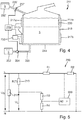
- FIG. 4 A third embodiment of a heating device 211 according to the invention is shown, which is designed as an evaporator.
- a heating device 211 For water 5 to be evaporated, it has a short upright pipe 213 corresponding to the fluid chamber, which has a circular cross section. Its diameter is larger than its height, but this can also vary significantly.
- a first heating element 217a is arranged all the way around or largely all the way around.
- a second heating element 217b of corresponding design On the outside of the tube 213 or its jacket side, a first heating element 217a is arranged all the way around or largely all the way around. Below this is arranged a second heating element 217b of corresponding design.
- the heating elements 217a and 217b can be similar to several heating conductors Fig. 3 with a horizontal parallel course.
- the heating elements 217a and 217b have a corresponding layer structure Fig.
- the heating elements 217a and 217b are connected to a controller 229.
- the dielectric insulation layers, not shown, are connected to a measuring device 230, which in turn is connected to the controller 229.
- the controller 229 can have or essentially consists of a controller, at least as far as the intelligent control functions are concerned. Above all, the controller 229 also controls the operation of the heating elements 217a and 217b, possibly independently of one another. With regard to the structure of the EP 3278691 A1 directed. Water 5 in the tube 213 is heated and evaporated by means of the heating elements 217a and 217b, so that the water vapor can escape from the heating device 211 at the top. As described there, temperature monitoring is of great importance, for which the invention also plays a role here due to the increased accuracy achieved.
- a relatively small calcification 239 is shown in simplified form at the top right. It has the effect that in this area the heating element 217a cannot give off its heat sufficiently well to the water 5 in the tube 213, so that an overheating mentioned at the beginning or a so-called hotspot can occur. This can be recognized particularly well with the detection of the temperature according to the invention.
- a water tank 232 is provided with a pump 234 controlled by the controller 239 in order to refill water 5 from the water tank 232 into the heating device 211 or into the fluid chamber of the pipe 213. This is done especially when it has been determined that the water level in tube 213 has dropped significantly. This is shown by the dashed line below the upper heating element 217a. At the latest then this upper heating element 217a will overheat considerably, and water must be topped up for an optimal function of the evaporation and above all for damage due to the overheating to prevent. This replenishment of water is then carried out by the controller 229 by means of the pump 234 when it has recognized the rising temperature.
- a further water tank 232 ' is shown with water 5 in the top left of the heating device 211. It is arranged above the tube 213, so that water can automatically flow into the tube 213 or the fluid chamber through a feed line 235 '.
- the control 229 can correspondingly open a valve 237 in the feed line 235 '.
- the measuring device 230 is shown in detail, which in turn is connected to the control 229 or the corresponding controller.
- the voltage U N is the line voltage and is applied to a single heating element 217, which is shown here. If there were several heating elements, they would probably be connected to the mains voltage U N in parallel with one another.
- the dielectric insulation layer is represented by the temperature-dependent resistor R (T) 219.
- the leakage voltage U L is present here with respect to ground N, since a corresponding leakage current flows out via the dielectric insulation layer.
- the two resistors R3 and R4 are provided as voltage dividers in the measuring device 230.
- the center tap goes directly to an AD input AD of the controller. This was explained at the beginning.
- a further voltage divider comprising resistors R1 and R2 is provided in order to tap the line voltage U N at phase L and also to pass it to an input of the controller of controller 229.
- the voltage dividers or a voltage divider network or resistance network formed thereby can also be designed differently.
- the leakage voltage U L is divided by the measured mains voltage U N , and this quotient is then advantageously multiplied by a compensation value.
- 230 is selected because the heating device 211 is to be operated with a mains voltage U N of 230 V. This gives you a standardized leak signal. This can then be evaluated with regard to its absolute value or with regard to its slope, that is to say the first derivative of the course. This is done with the 6 and 7 explained. Depending on which of the known overtemperature cases is recognized therefrom, water 5 can be refilled into the fluid chamber or the heating power of one of the heating elements 217 or all heating elements can be reduced or switched off.
- Fig. 6 it is shown over time t how the mains voltage U N and the leakage voltage U L dependent thereon run.
- the invention has not yet been implemented here.
- At the very bottom is shown corresponding to the right vertical axis as the activity state of the pump 234 corresponds Fig. 4 is whether water needs to be pumped in again.
- the operation of the evaporator with heating device 211 is such that something is briefly pumped every 28 seconds in order to refill water. This can be seen in the interval between 750 sec and 850 sec and from 890 sec.However, since there are jumps in the mains voltage U N , in particular if a further strong heating device of the baking oven is switched on or off as a consumer as a consumer when the heating device is arranged in an evaporator within a baking oven If the jumps are not negligible, an error occurs. These jumps up here occur at about 720 sec and about 860 sec. At about 805 sec and 950 sec the jumps occur downwards. This depends on switching the additional consumer on and off.
- the mains voltage U N fluctuates again, but at slightly different times. It can be seen that the detection and consideration of this fluctuation in the mains voltage U N at the heating device, which indeed influences the leakage voltage U L , can be compensated for in such a way that the pumping at the pump 234 takes place at the desired regular intervals. Above all, this can also be seen in the regularity of the course of the leakage voltage U L. If the jumps occur in the mains voltage U N , the leakage voltage U L does not change. This enables better temperature detection, and the heater 211 can also be operated better.
- This effect is easily imaginable, and is equally advantageous when recognizing, for example, a hotspot or local overheating by calcification 239 Fig. 4 ,
- This overheating causes the leakage voltage U L to increase , since an increased leakage current flows in this area.
- a sudden increase in the line voltage U N with which the heating element is operated and thus a corresponding jump in the leakage voltage inevitably occurs can be compensated for.
Landscapes
- Engineering & Computer Science (AREA)
- Physics & Mathematics (AREA)
- Thermal Sciences (AREA)
- General Engineering & Computer Science (AREA)
- Mechanical Engineering (AREA)
- Chemical & Material Sciences (AREA)
- Combustion & Propulsion (AREA)
- Fluid Mechanics (AREA)
- General Physics & Mathematics (AREA)
- Life Sciences & Earth Sciences (AREA)
- Sustainable Development (AREA)
- Sustainable Energy (AREA)
- Ceramic Engineering (AREA)
- Food Science & Technology (AREA)
- Control Of Resistance Heating (AREA)
Applications Claiming Priority (1)
| Application Number | Priority Date | Filing Date | Title |
|---|---|---|---|
| DE102018213869.9A DE102018213869B4 (de) | 2018-08-17 | 2018-08-17 | Heizeinrichtung und Verfahren zum Betrieb einer Heizeinrichtung |
Publications (2)
| Publication Number | Publication Date |
|---|---|
| EP3614797A1 true EP3614797A1 (fr) | 2020-02-26 |
| EP3614797B1 EP3614797B1 (fr) | 2022-04-20 |
Family
ID=67514288
Family Applications (1)
| Application Number | Title | Priority Date | Filing Date |
|---|---|---|---|
| EP19188759.5A Active EP3614797B1 (fr) | 2018-08-17 | 2019-07-29 | Dispositif de chauffage et procédé de fonctionnement d'un dispositif de chauffage |
Country Status (6)
| Country | Link |
|---|---|
| US (1) | US11585574B2 (fr) |
| EP (1) | EP3614797B1 (fr) |
| KR (1) | KR102796984B1 (fr) |
| CN (1) | CN110836532B (fr) |
| DE (1) | DE102018213869B4 (fr) |
| PL (1) | PL3614797T3 (fr) |
Families Citing this family (5)
| Publication number | Priority date | Publication date | Assignee | Title |
|---|---|---|---|---|
| US12540757B2 (en) | 2016-03-02 | 2026-02-03 | Watlow Electric Manufacturing Company | Heater bundles with local power switching |
| DE102020207784A1 (de) * | 2020-06-23 | 2021-12-23 | E.G.O. Elektro-Gerätebau GmbH | Heizeinrichtung mit einer Temperaturmesseinrichtung und Verfahren zur Temperaturmessung an der Heizeinrichtung und zur Herstellung |
| US11796223B2 (en) * | 2020-09-15 | 2023-10-24 | B/E Aerospace, Inc. | System for preventing overheating in aircraft galley inserts |
| CN112462824A (zh) * | 2020-11-12 | 2021-03-09 | 宣城睿晖宣晟企业管理中心合伙企业(有限合伙) | 一种薄膜沉积设备加热控制系统及方法 |
| EP4650670A1 (fr) * | 2024-05-17 | 2025-11-19 | B/E Aerospace, Inc. | Appareil de collecte de calcaire |
Citations (8)
| Publication number | Priority date | Publication date | Assignee | Title |
|---|---|---|---|---|
| EP1152639A2 (fr) | 2000-05-03 | 2001-11-07 | E.G.O. Elektro-Gerätebau GmbH | Unité de chauffage électrique, particulièrement destiné à des milieux liquides |
| WO2010008279A1 (fr) * | 2008-07-15 | 2010-01-21 | Otter Controls Limited | Élément chauffant et procédé d’utilisation associé |
| DE102010043727A1 (de) | 2010-11-10 | 2012-05-10 | E.G.O. Elektro-Gerätebau GmbH | Pumpe |
| DE102013200277A1 (de) | 2013-01-10 | 2014-01-30 | E.G.O. Elektro-Gerätebau GmbH | Heizeinrichtung und Verfahren zur Temperaturmessung an der Heizeinrichtung |
| EP3096585A1 (fr) | 2015-05-18 | 2016-11-23 | E.G.O. ELEKTRO-GERÄTEBAU GmbH | Dispositif de chauffage destiné à chauffer des fluides et procédé de fonctionnement d'un tel dispositif de chauffage |
| EP3145273A1 (fr) | 2015-09-21 | 2017-03-22 | E.G.O. ELEKTRO-GERÄTEBAU GmbH | Dispositif de chauffage d'eau et procede de fonctionnement d'un tel dispositif de chauffage |
| EP3197241A1 (fr) * | 2016-01-19 | 2017-07-26 | E.G.O. ELEKTRO-GERÄTEBAU GmbH | Dispositif de chauffage et procede de mesure des temperatures sur un dispositif de chauffage |
| EP3278691A1 (fr) | 2016-08-02 | 2018-02-07 | E.G.O. ELEKTRO-GERÄTEBAU GmbH | Évaporateur et appareil de cuisson comprenant un tel dispositif |
Family Cites Families (21)
| Publication number | Priority date | Publication date | Assignee | Title |
|---|---|---|---|---|
| US4092520A (en) * | 1976-12-16 | 1978-05-30 | Baxter Travenol Laboratories, Inc. | Leakage current thermostat |
| JP2652430B2 (ja) * | 1988-10-21 | 1997-09-10 | 松下電工株式会社 | 多分割感熱面状発熱体 |
| CN2056983U (zh) | 1989-05-18 | 1990-05-09 | 陈非 | 全自动电热水淋浴器 |
| DE19612170A1 (de) * | 1996-03-27 | 1997-10-02 | Patent Treuhand Ges Fuer Elektrische Gluehlampen Mbh | Schaltungsanordnung zum Betrieb von elektrischen Lampen und Betriebsverfahren für elektrische Lampen |
| JPH10247579A (ja) * | 1997-03-05 | 1998-09-14 | Furukawa Electric Co Ltd:The | 電気暖房器 |
| WO1999027828A1 (fr) * | 1997-12-02 | 1999-06-10 | Koninklijke Philips Electronics N.V. | Recipient de chauffage et procede de commande de l'element chauffant de ce recipient |
| IT1306477B1 (it) * | 1998-10-13 | 2001-06-11 | Hydor Srl | Dispositivo riscaldatore termostatico per liquidi, in particolare perl'acqua di acquari. |
| NL1014601C2 (nl) | 2000-03-10 | 2001-09-11 | Ferro Techniek Bv | Verwarmingselement, vloeistofhouder en werkwijze voor het waarnemen van temperatuurwisselingen. |
| JP2004281121A (ja) | 2003-03-13 | 2004-10-07 | Sanyo Electric Co Ltd | 漏電遮断器 |
| NL1027571C2 (nl) | 2004-11-23 | 2006-05-24 | Ferro Techniek Holding Bv | Emailsamenstelling voor toepassing als dielektricum, en gebruik van een dergelijke emailsamenstelling. |
| ES2303167T3 (es) | 2005-09-23 | 2008-08-01 | CATEM GMBH & CO. KG | Elemento generador de calor de un dispositivo calefactor. |
| US7256372B2 (en) | 2005-12-07 | 2007-08-14 | Aos Holding Company | Fluid-heating apparatus, circuit for heating a fluid, and method of operating the same |
| NL2000081C2 (nl) | 2006-05-23 | 2007-11-26 | Ferro Techniek Holding Bv | Elektrische verwarmingsinrichting met temperatuurdetectie door dielektrische laag. |
| US7576305B2 (en) | 2006-09-22 | 2009-08-18 | Catem Gmbh & Co. Kg | Heat-generating element of a heating device |
| US8378271B2 (en) | 2007-07-11 | 2013-02-19 | International Business Machines Corporation | Utilization of overvoltage and overcurrent compensation to extend the usable operating range of electronic devices |
| KR100965302B1 (ko) | 2008-05-06 | 2010-06-22 | 중앙제어 주식회사 | 누수 감지 장치 |
| JP2011058962A (ja) * | 2009-09-10 | 2011-03-24 | Kurimoto Ltd | 整流形直流電源による直接抵抗加熱装置における原料温度計測方法及びその計測装置 |
| JP5349653B2 (ja) | 2012-06-13 | 2013-11-20 | 三菱電機株式会社 | 誘導加熱調理器 |
| DE102012213385A1 (de) * | 2012-07-30 | 2014-05-22 | E.G.O. Elektro-Gerätebau GmbH | Heizeinrichtung und Elektrogerät mit Heizeinrichtung |
| DE102013201903A1 (de) * | 2013-02-06 | 2014-08-07 | E.G.O. Elektro-Gerätebau GmbH | Wärmepumpenvorrichtung, Verwendung einer Pumpe mit beheizbarer Pumpenkammer in einer Wärmepumpenvorrichtung und Verfahren zum Betrieb einer Wärmepumpenvorrichtung |
| US10117292B2 (en) | 2013-04-19 | 2018-10-30 | Chromalox, Inc. | Medium voltage heater elements moisture detection circuit |
-
2018
- 2018-08-17 DE DE102018213869.9A patent/DE102018213869B4/de active Active
-
2019
- 2019-07-29 PL PL19188759.5T patent/PL3614797T3/pl unknown
- 2019-07-29 EP EP19188759.5A patent/EP3614797B1/fr active Active
- 2019-08-15 US US16/541,246 patent/US11585574B2/en active Active
- 2019-08-16 KR KR1020190100481A patent/KR102796984B1/ko active Active
- 2019-08-19 CN CN201910763938.1A patent/CN110836532B/zh active Active
Patent Citations (8)
| Publication number | Priority date | Publication date | Assignee | Title |
|---|---|---|---|---|
| EP1152639A2 (fr) | 2000-05-03 | 2001-11-07 | E.G.O. Elektro-Gerätebau GmbH | Unité de chauffage électrique, particulièrement destiné à des milieux liquides |
| WO2010008279A1 (fr) * | 2008-07-15 | 2010-01-21 | Otter Controls Limited | Élément chauffant et procédé d’utilisation associé |
| DE102010043727A1 (de) | 2010-11-10 | 2012-05-10 | E.G.O. Elektro-Gerätebau GmbH | Pumpe |
| DE102013200277A1 (de) | 2013-01-10 | 2014-01-30 | E.G.O. Elektro-Gerätebau GmbH | Heizeinrichtung und Verfahren zur Temperaturmessung an der Heizeinrichtung |
| EP3096585A1 (fr) | 2015-05-18 | 2016-11-23 | E.G.O. ELEKTRO-GERÄTEBAU GmbH | Dispositif de chauffage destiné à chauffer des fluides et procédé de fonctionnement d'un tel dispositif de chauffage |
| EP3145273A1 (fr) | 2015-09-21 | 2017-03-22 | E.G.O. ELEKTRO-GERÄTEBAU GmbH | Dispositif de chauffage d'eau et procede de fonctionnement d'un tel dispositif de chauffage |
| EP3197241A1 (fr) * | 2016-01-19 | 2017-07-26 | E.G.O. ELEKTRO-GERÄTEBAU GmbH | Dispositif de chauffage et procede de mesure des temperatures sur un dispositif de chauffage |
| EP3278691A1 (fr) | 2016-08-02 | 2018-02-07 | E.G.O. ELEKTRO-GERÄTEBAU GmbH | Évaporateur et appareil de cuisson comprenant un tel dispositif |
Also Published As
| Publication number | Publication date |
|---|---|
| US11585574B2 (en) | 2023-02-21 |
| PL3614797T3 (pl) | 2022-09-12 |
| EP3614797B1 (fr) | 2022-04-20 |
| CN110836532A (zh) | 2020-02-25 |
| KR20200020642A (ko) | 2020-02-26 |
| CN110836532B (zh) | 2023-03-10 |
| US20200056811A1 (en) | 2020-02-20 |
| DE102018213869A1 (de) | 2020-02-20 |
| DE102018213869B4 (de) | 2020-03-05 |
| KR102796984B1 (ko) | 2025-04-21 |
Similar Documents
| Publication | Publication Date | Title |
|---|---|---|
| EP3614797B1 (fr) | Dispositif de chauffage et procédé de fonctionnement d'un dispositif de chauffage | |
| EP3145273B1 (fr) | Dispositif de chauffage d'eau et procede de fonctionnement d'un tel dispositif de chauffage | |
| EP3088800B1 (fr) | Dispositif de chauffage de liquides, evaporateur pour un appareil de cuisson electrique et procede de fonctionnement d'un dispositif de chauffage | |
| EP1152639B1 (fr) | Unité de chauffage électrique, particulièrement destiné à des milieux liquides | |
| EP3278691B1 (fr) | Évaporateur et appareil de cuisson comprenant un tel dispositif | |
| EP3096585B1 (fr) | Dispositif de chauffage destiné à chauffer des fluides et procédé de fonctionnement d'un tel dispositif de chauffage | |
| EP1870641B1 (fr) | Dispositif d'évaporation et procédé de fonctionnement du dispositif d'évaporation | |
| EP2693835A1 (fr) | Dispositif de chauffage et appareil électrique doté d'un dispositif de chauffage | |
| EP3100014B1 (fr) | Mesure de température sur un système de chauffage par rayonnement pour un appareil ménager | |
| EP3197241B1 (fr) | Dispositif de chauffage et procede de mesure des temperatures sur un dispositif de chauffage | |
| EP2793008B1 (fr) | Calibrateur pour calibrer des dispositifs de mesure de température | |
| DE60116609T2 (de) | Flüssigkeit enthaltendes heizelement und verfahren zum erfassen von temperaturveränderungen | |
| EP3250003A1 (fr) | Dispositif de chauffage | |
| DE3512659A1 (de) | Heizung fuer elektrisch betriebene warmwassergeraete | |
| EP3637948B1 (fr) | Dispositif de chauffage et procédé d'enregistrement de température sur un dispositif de chauffage | |
| EP2840404A1 (fr) | Chauffe-eau électrique instantané à fil nu et procédé de commande de celui-ci | |
| EP3598848B1 (fr) | Dispositif de chauffage pour une table de cuisson et table de cuisson | |
| WO2009027042A1 (fr) | Dispositif de chauffage, procédé pour faire fonctionner un dispositif de chauffage et appareil de chauffage électrique appartenant à un tel dispositif de chauffage | |
| DE102015218120B4 (de) | Verfahren zum Betrieb einer Heizeinrichtung zum Erhitzen von Wasser , Heizeinrichtung und Geschirrspülmaschine | |
| DE60118378T2 (de) | Rohrförmiges heizelement | |
| DE102018203609B4 (de) | Verfahren und Vorrichtung zur Erfassung einer Temperatur an einem Heizelement | |
| DE19934319A1 (de) | Heizvorrichtung mit Laugentemperaturregelung | |
| WO2023213616A1 (fr) | Dispositif de chauffage par rayonnement et table de cuisson ayant un dispositif de chauffage par rayonnement | |
| DE102015218121A1 (de) | Heizeinrichtung zum Erhitzen von Wasser und Verfahren zum Betrieb einer solchen Heizeinrichtung | |
| EP3771287A1 (fr) | Dispositif chauffant à rayonnement et plaque de cuisson dotée d'un tel dispositif chauffant à rayonnement |
Legal Events
| Date | Code | Title | Description |
|---|---|---|---|
| PUAI | Public reference made under article 153(3) epc to a published international application that has entered the european phase |
Free format text: ORIGINAL CODE: 0009012 |
|
| STAA | Information on the status of an ep patent application or granted ep patent |
Free format text: STATUS: THE APPLICATION HAS BEEN PUBLISHED |
|
| AK | Designated contracting states |
Kind code of ref document: A1 Designated state(s): AL AT BE BG CH CY CZ DE DK EE ES FI FR GB GR HR HU IE IS IT LI LT LU LV MC MK MT NL NO PL PT RO RS SE SI SK SM TR |
|
| AX | Request for extension of the european patent |
Extension state: BA ME |
|
| STAA | Information on the status of an ep patent application or granted ep patent |
Free format text: STATUS: REQUEST FOR EXAMINATION WAS MADE |
|
| 17P | Request for examination filed |
Effective date: 20200728 |
|
| RBV | Designated contracting states (corrected) |
Designated state(s): AL AT BE BG CH CY CZ DE DK EE ES FI FR GB GR HR HU IE IS IT LI LT LU LV MC MK MT NL NO PL PT RO RS SE SI SK SM TR |
|
| GRAP | Despatch of communication of intention to grant a patent |
Free format text: ORIGINAL CODE: EPIDOSNIGR1 |
|
| STAA | Information on the status of an ep patent application or granted ep patent |
Free format text: STATUS: GRANT OF PATENT IS INTENDED |
|
| INTG | Intention to grant announced |
Effective date: 20211222 |
|
| GRAS | Grant fee paid |
Free format text: ORIGINAL CODE: EPIDOSNIGR3 |
|
| GRAA | (expected) grant |
Free format text: ORIGINAL CODE: 0009210 |
|
| STAA | Information on the status of an ep patent application or granted ep patent |
Free format text: STATUS: THE PATENT HAS BEEN GRANTED |
|
| AK | Designated contracting states |
Kind code of ref document: B1 Designated state(s): AL AT BE BG CH CY CZ DE DK EE ES FI FR GB GR HR HU IE IS IT LI LT LU LV MC MK MT NL NO PL PT RO RS SE SI SK SM TR |
|
| REG | Reference to a national code |
Ref country code: GB Ref legal event code: FG4D Free format text: NOT ENGLISH |
|
| REG | Reference to a national code |
Ref country code: CH Ref legal event code: EP |
|
| REG | Reference to a national code |
Ref country code: IE Ref legal event code: FG4D Free format text: LANGUAGE OF EP DOCUMENT: GERMAN |
|
| REG | Reference to a national code |
Ref country code: DE Ref legal event code: R096 Ref document number: 502019004100 Country of ref document: DE |
|
| REG | Reference to a national code |
Ref country code: AT Ref legal event code: REF Ref document number: 1486180 Country of ref document: AT Kind code of ref document: T Effective date: 20220515 |
|
| REG | Reference to a national code |
Ref country code: LT Ref legal event code: MG9D |
|
| REG | Reference to a national code |
Ref country code: NL Ref legal event code: MP Effective date: 20220420 |
|
| PG25 | Lapsed in a contracting state [announced via postgrant information from national office to epo] |
Ref country code: NL Free format text: LAPSE BECAUSE OF FAILURE TO SUBMIT A TRANSLATION OF THE DESCRIPTION OR TO PAY THE FEE WITHIN THE PRESCRIBED TIME-LIMIT Effective date: 20220420 |
|
| PG25 | Lapsed in a contracting state [announced via postgrant information from national office to epo] |
Ref country code: SE Free format text: LAPSE BECAUSE OF FAILURE TO SUBMIT A TRANSLATION OF THE DESCRIPTION OR TO PAY THE FEE WITHIN THE PRESCRIBED TIME-LIMIT Effective date: 20220420 Ref country code: PT Free format text: LAPSE BECAUSE OF FAILURE TO SUBMIT A TRANSLATION OF THE DESCRIPTION OR TO PAY THE FEE WITHIN THE PRESCRIBED TIME-LIMIT Effective date: 20220822 Ref country code: NO Free format text: LAPSE BECAUSE OF FAILURE TO SUBMIT A TRANSLATION OF THE DESCRIPTION OR TO PAY THE FEE WITHIN THE PRESCRIBED TIME-LIMIT Effective date: 20220720 Ref country code: LT Free format text: LAPSE BECAUSE OF FAILURE TO SUBMIT A TRANSLATION OF THE DESCRIPTION OR TO PAY THE FEE WITHIN THE PRESCRIBED TIME-LIMIT Effective date: 20220420 Ref country code: HR Free format text: LAPSE BECAUSE OF FAILURE TO SUBMIT A TRANSLATION OF THE DESCRIPTION OR TO PAY THE FEE WITHIN THE PRESCRIBED TIME-LIMIT Effective date: 20220420 Ref country code: GR Free format text: LAPSE BECAUSE OF FAILURE TO SUBMIT A TRANSLATION OF THE DESCRIPTION OR TO PAY THE FEE WITHIN THE PRESCRIBED TIME-LIMIT Effective date: 20220721 Ref country code: FI Free format text: LAPSE BECAUSE OF FAILURE TO SUBMIT A TRANSLATION OF THE DESCRIPTION OR TO PAY THE FEE WITHIN THE PRESCRIBED TIME-LIMIT Effective date: 20220420 Ref country code: ES Free format text: LAPSE BECAUSE OF FAILURE TO SUBMIT A TRANSLATION OF THE DESCRIPTION OR TO PAY THE FEE WITHIN THE PRESCRIBED TIME-LIMIT Effective date: 20220420 Ref country code: BG Free format text: LAPSE BECAUSE OF FAILURE TO SUBMIT A TRANSLATION OF THE DESCRIPTION OR TO PAY THE FEE WITHIN THE PRESCRIBED TIME-LIMIT Effective date: 20220720 |
|
| PG25 | Lapsed in a contracting state [announced via postgrant information from national office to epo] |
Ref country code: RS Free format text: LAPSE BECAUSE OF FAILURE TO SUBMIT A TRANSLATION OF THE DESCRIPTION OR TO PAY THE FEE WITHIN THE PRESCRIBED TIME-LIMIT Effective date: 20220420 Ref country code: LV Free format text: LAPSE BECAUSE OF FAILURE TO SUBMIT A TRANSLATION OF THE DESCRIPTION OR TO PAY THE FEE WITHIN THE PRESCRIBED TIME-LIMIT Effective date: 20220420 Ref country code: IS Free format text: LAPSE BECAUSE OF FAILURE TO SUBMIT A TRANSLATION OF THE DESCRIPTION OR TO PAY THE FEE WITHIN THE PRESCRIBED TIME-LIMIT Effective date: 20220820 |
|
| REG | Reference to a national code |
Ref country code: DE Ref legal event code: R097 Ref document number: 502019004100 Country of ref document: DE |
|
| PG25 | Lapsed in a contracting state [announced via postgrant information from national office to epo] |
Ref country code: SM Free format text: LAPSE BECAUSE OF FAILURE TO SUBMIT A TRANSLATION OF THE DESCRIPTION OR TO PAY THE FEE WITHIN THE PRESCRIBED TIME-LIMIT Effective date: 20220420 Ref country code: SK Free format text: LAPSE BECAUSE OF FAILURE TO SUBMIT A TRANSLATION OF THE DESCRIPTION OR TO PAY THE FEE WITHIN THE PRESCRIBED TIME-LIMIT Effective date: 20220420 Ref country code: RO Free format text: LAPSE BECAUSE OF FAILURE TO SUBMIT A TRANSLATION OF THE DESCRIPTION OR TO PAY THE FEE WITHIN THE PRESCRIBED TIME-LIMIT Effective date: 20220420 Ref country code: EE Free format text: LAPSE BECAUSE OF FAILURE TO SUBMIT A TRANSLATION OF THE DESCRIPTION OR TO PAY THE FEE WITHIN THE PRESCRIBED TIME-LIMIT Effective date: 20220420 Ref country code: DK Free format text: LAPSE BECAUSE OF FAILURE TO SUBMIT A TRANSLATION OF THE DESCRIPTION OR TO PAY THE FEE WITHIN THE PRESCRIBED TIME-LIMIT Effective date: 20220420 Ref country code: CZ Free format text: LAPSE BECAUSE OF FAILURE TO SUBMIT A TRANSLATION OF THE DESCRIPTION OR TO PAY THE FEE WITHIN THE PRESCRIBED TIME-LIMIT Effective date: 20220420 |
|
| REG | Reference to a national code |
Ref country code: DE Ref legal event code: R119 Ref document number: 502019004100 Country of ref document: DE |
|
| PLBE | No opposition filed within time limit |
Free format text: ORIGINAL CODE: 0009261 |
|
| STAA | Information on the status of an ep patent application or granted ep patent |
Free format text: STATUS: NO OPPOSITION FILED WITHIN TIME LIMIT |
|
| PG25 | Lapsed in a contracting state [announced via postgrant information from national office to epo] |
Ref country code: MC Free format text: LAPSE BECAUSE OF FAILURE TO SUBMIT A TRANSLATION OF THE DESCRIPTION OR TO PAY THE FEE WITHIN THE PRESCRIBED TIME-LIMIT Effective date: 20220420 |
|
| REG | Reference to a national code |
Ref country code: CH Ref legal event code: PL |
|
| 26N | No opposition filed |
Effective date: 20230123 |
|
| REG | Reference to a national code |
Ref country code: BE Ref legal event code: MM Effective date: 20220731 |
|
| PG25 | Lapsed in a contracting state [announced via postgrant information from national office to epo] |
Ref country code: AL Free format text: LAPSE BECAUSE OF FAILURE TO SUBMIT A TRANSLATION OF THE DESCRIPTION OR TO PAY THE FEE WITHIN THE PRESCRIBED TIME-LIMIT Effective date: 20220420 |
|
| PG25 | Lapsed in a contracting state [announced via postgrant information from national office to epo] |
Ref country code: LU Free format text: LAPSE BECAUSE OF NON-PAYMENT OF DUE FEES Effective date: 20220729 Ref country code: LI Free format text: LAPSE BECAUSE OF NON-PAYMENT OF DUE FEES Effective date: 20220731 Ref country code: CH Free format text: LAPSE BECAUSE OF NON-PAYMENT OF DUE FEES Effective date: 20220731 |
|
| PG25 | Lapsed in a contracting state [announced via postgrant information from national office to epo] |
Ref country code: SI Free format text: LAPSE BECAUSE OF FAILURE TO SUBMIT A TRANSLATION OF THE DESCRIPTION OR TO PAY THE FEE WITHIN THE PRESCRIBED TIME-LIMIT Effective date: 20220420 Ref country code: DE Free format text: LAPSE BECAUSE OF NON-PAYMENT OF DUE FEES Effective date: 20230201 Ref country code: BE Free format text: LAPSE BECAUSE OF NON-PAYMENT OF DUE FEES Effective date: 20220731 |
|
| PG25 | Lapsed in a contracting state [announced via postgrant information from national office to epo] |
Ref country code: IE Free format text: LAPSE BECAUSE OF NON-PAYMENT OF DUE FEES Effective date: 20220729 |
|
| GBPC | Gb: european patent ceased through non-payment of renewal fee |
Effective date: 20230729 |
|
| PG25 | Lapsed in a contracting state [announced via postgrant information from national office to epo] |
Ref country code: HU Free format text: LAPSE BECAUSE OF FAILURE TO SUBMIT A TRANSLATION OF THE DESCRIPTION OR TO PAY THE FEE WITHIN THE PRESCRIBED TIME-LIMIT; INVALID AB INITIO Effective date: 20190729 |
|
| PG25 | Lapsed in a contracting state [announced via postgrant information from national office to epo] |
Ref country code: MK Free format text: LAPSE BECAUSE OF FAILURE TO SUBMIT A TRANSLATION OF THE DESCRIPTION OR TO PAY THE FEE WITHIN THE PRESCRIBED TIME-LIMIT Effective date: 20220420 Ref country code: CY Free format text: LAPSE BECAUSE OF FAILURE TO SUBMIT A TRANSLATION OF THE DESCRIPTION OR TO PAY THE FEE WITHIN THE PRESCRIBED TIME-LIMIT Effective date: 20220420 Ref country code: GB Free format text: LAPSE BECAUSE OF NON-PAYMENT OF DUE FEES Effective date: 20230729 |
|
| PG25 | Lapsed in a contracting state [announced via postgrant information from national office to epo] |
Ref country code: MT Free format text: LAPSE BECAUSE OF FAILURE TO SUBMIT A TRANSLATION OF THE DESCRIPTION OR TO PAY THE FEE WITHIN THE PRESCRIBED TIME-LIMIT Effective date: 20220420 |
|
| PG25 | Lapsed in a contracting state [announced via postgrant information from national office to epo] |
Ref country code: BG Free format text: LAPSE BECAUSE OF FAILURE TO SUBMIT A TRANSLATION OF THE DESCRIPTION OR TO PAY THE FEE WITHIN THE PRESCRIBED TIME-LIMIT Effective date: 20220420 |
|
| PG25 | Lapsed in a contracting state [announced via postgrant information from national office to epo] |
Ref country code: BG Free format text: LAPSE BECAUSE OF FAILURE TO SUBMIT A TRANSLATION OF THE DESCRIPTION OR TO PAY THE FEE WITHIN THE PRESCRIBED TIME-LIMIT Effective date: 20220420 |
|
| PGFP | Annual fee paid to national office [announced via postgrant information from national office to epo] |
Ref country code: PL Payment date: 20250630 Year of fee payment: 7 |
|
| REG | Reference to a national code |
Ref country code: AT Ref legal event code: MM01 Ref document number: 1486180 Country of ref document: AT Kind code of ref document: T Effective date: 20240729 |
|
| PGFP | Annual fee paid to national office [announced via postgrant information from national office to epo] |
Ref country code: TR Payment date: 20250724 Year of fee payment: 7 Ref country code: IT Payment date: 20250731 Year of fee payment: 7 |
|
| PG25 | Lapsed in a contracting state [announced via postgrant information from national office to epo] |
Ref country code: AT Free format text: LAPSE BECAUSE OF NON-PAYMENT OF DUE FEES Effective date: 20240729 |
|
| PGFP | Annual fee paid to national office [announced via postgrant information from national office to epo] |
Ref country code: FR Payment date: 20250723 Year of fee payment: 7 |
|
| PGFP | Annual fee paid to national office [announced via postgrant information from national office to epo] |
Ref country code: AT Payment date: 20260410 Year of fee payment: 5 |