EP3614937B1 - Instrument chirurgical de construction à deux branches avec facilité de nettoyage améliorée - Google Patents
Instrument chirurgical de construction à deux branches avec facilité de nettoyage améliorée Download PDFInfo
- Publication number
- EP3614937B1 EP3614937B1 EP18722009.0A EP18722009A EP3614937B1 EP 3614937 B1 EP3614937 B1 EP 3614937B1 EP 18722009 A EP18722009 A EP 18722009A EP 3614937 B1 EP3614937 B1 EP 3614937B1
- Authority
- EP
- European Patent Office
- Prior art keywords
- instrument
- branch
- branches
- elongated hole
- width
- Prior art date
- Legal status (The legal status is an assumption and is not a legal conclusion. Google has not performed a legal analysis and makes no representation as to the accuracy of the status listed.)
- Active
Links
Images


Classifications
-
- A—HUMAN NECESSITIES
- A61—MEDICAL OR VETERINARY SCIENCE; HYGIENE
- A61B—DIAGNOSIS; SURGERY; IDENTIFICATION
- A61B17/00—Surgical instruments, devices or methods
- A61B17/32—Surgical cutting instruments
- A61B17/3201—Scissors
-
- A—HUMAN NECESSITIES
- A61—MEDICAL OR VETERINARY SCIENCE; HYGIENE
- A61B—DIAGNOSIS; SURGERY; IDENTIFICATION
- A61B17/00—Surgical instruments, devices or methods
- A61B17/28—Surgical forceps
- A61B17/2812—Surgical forceps with a single pivotal connection
- A61B17/2816—Pivots
-
- A—HUMAN NECESSITIES
- A61—MEDICAL OR VETERINARY SCIENCE; HYGIENE
- A61B—DIAGNOSIS; SURGERY; IDENTIFICATION
- A61B90/00—Instruments, implements or accessories specially adapted for surgery or diagnosis and not covered by any of the groups A61B1/00 - A61B50/00, e.g. for luxation treatment or for protecting wound edges
- A61B90/08—Accessories or related features not otherwise provided for
- A61B2090/0813—Accessories designed for easy sterilising, i.e. re-usable
Definitions
- the invention relates to a scissors or forceps-like medical instrument with a first instrument branch (instrument part) consisting of a distal engagement/acting section, a proximal gripping/holding section and a coupling/closing section arranged in between, a second instrument branch (instrument part) also consisting of a distal engagement/acting section, a proximal gripping/holding section and a coupling/closing section arranged in between and a bearing element which couples the instrument branches (instrument parts) in a closed position, whereby the two instrument branches (instrument parts) can be pivoted in relation to one another in the manner of scissors and can be pivoted contact each other (slidingly) in a working pivoting range via contact surfaces facing each other in the respective coupling/closing sections, so that the two instrument branches in the working pivoting range rest on and guide each other with their respective contact surfaces (i.e.
- the bearing element preferably being threadless and being fixed directly to the first instrument branch at one end section and becoming continuously conical or has a stepped, conically widening head, which passes through a continuous or stepped, conical through-opening in the second instrument branch, the through-opening being designed in the form of a slot.
- a scissors or pliers-like medical instrument with a first and a second branch (instrument part) is known, which are pivotally connected to one another via a bearing pin provided with a radially expanded head part on the one hand and a screw thread on the other.
- the first branch forms a guide plate and the second branch forms a bearing plate into which the bearing journal is screwed.
- the guide plate has an opening for pivotably receiving the bearing pin. The guide plate and the bearing plate are in full contact with one another when the instrument is in its normal operating state.
- the opening in the guide plate is designed as an elongated hole (i.e. a continuous longitudinal groove) extending in the longitudinal direction of the guide plate, which has a first enlarged depression in the edge area of its end area adjacent to the tool part and a second enlarged depression in the edge area of its end area lying opposite in the longitudinal direction, in which the Head part of the bearing pin is optionally recordable.
- the first indentation has a shallower depth (T1) than the second indentation.
- the bearing plate On its contact surface facing the guide plate, the bearing plate has a transverse groove (indentation) arranged in the region of the bearing journal and running transversely to the bearing plate, the depth (T3) of which corresponds at least to the depth (T1) of the first indentation of the elongated hole and the width (b ) corresponds at least to the width (B) of the guide plate.
- the first branch can be brought with its guide plate into a pivot position aligned with the transverse groove and can be adjusted in the direction towards the bearing journal in the transverse groove to such an extent that the head part of the bearing journal is connected to the first Deepening of the slot disengaged.
- the head part of the bearing pin is to be brought into engagement by adjusting the second branch with its bearing plate and the bearing pin along the slot with the second indentation of the slot and by adjusting in the direction of the bearing pin with the second indentation.
- the EP 2 873 381 A1 discloses a medical instrument consisting of a first hand lever (instrument part) having a guide plate and a second hand lever (instrument part) having a bearing plate, which are pivotably connected/coupled to one another via a bearing pin arranged in the region of the guide plate and the bearing plate and provided with a radially expanded head part are.
- the bearing plate forms a receiving groove into which the guide plate engages in its operating position.
- the bearing plate has a depression that extends over the entire width of the bearing plate.
- the guide plate is rotatable relative to the bearing plate from its operating position into a cleaning position in which the guide plate overlaps with the recess on the bearing plate.
- a spacer element is provided between the guide plate and the bearing plate, the height of which in the direction of the bearing pin is equal to or smaller than the depth of the recess, so that the guide plate in the Deepening overlapping angular position can not sink to the bottom of the deepening.
- the disadvantage of this instrument is that a visual check of the cleaning success in the final gap in the cleaning position is only possible to a limited extent.
- the edge areas of the bearing plate form transitions or steps that can interfere with dissection (e.g. knotting of suture material, pinching of tissue).
- a pivot pin protrudes through a second bearing plate and is provided with a radially widened annular flange in its end region protruding through the second bearing plate. This is at a distance (a) from a first bearing plate which corresponds to twice the thickness (d) of the second bearing plate mounted on the pivot pin or is greater than twice the thickness (d) of the second bearing plate, so that the second hand lever (instrument part) in an open pivot position to the first hand lever (instrument part) along the pivot pin is displaceable into a position in which the opposing contact surfaces of the flattened bearing plates are exposed.
- a disadvantage of this instrument is that the pivot pin protrudes beyond the end section.
- the edge areas of the bearing plate form transitions or steps, which can interfere with the preparation (eg knotting of suture material, pinching of tissue).
- the DE 297 12 016 U1 discloses a dismountable utility scissors in which instrument parts are detachably coupled. From the DE 20 2004 002 560 U1 a collapsible dental forceps is also known. With these instruments, the fact that the instrument can be dismantled causes additional work. In addition, a correct pairing of instrument halves must be ensured when reassembling after cleaning. Disadvantageously, there is also a certain risk of confusion with different instrument sizes.
- a surgical instrument is known with two branches pivotably connected to one another, which in the area of their pivot connection have flat bearing surfaces that abut one another when the branches are pivoted in their working area. Funds are provided that a relative displacement of the two branches out of their working area, partially cancel the flat contact of the contact surfaces.
- branches that can be moved into a cleaning position
- the susceptibility to wear is disadvantageous, with there also being no/poor visibility in the final section for visual inspection of the cleaning success.
- the assembly work is also high and the bearing pin can also be lost.
- CN 202723937 U discloses a pair of scissors having a first branch and a second branch that can be pivotally coupled to each other by means of a bushing and a trunnion.
- Instruments are also known in which a locking screw is screwed into one of the instrument branches against the stop (collar) and is slightly overtightened to secure it, as a result of which the thread turns are cold-welded.
- the end screw passes through a stepped bore in the other instrument branch and has a screw head that comes into contact with the other instrument branch and pushes/tensions it in the direction of one instrument branch.
- the course of the instrument results (resulting from the tension of the instrument branches against each other) from the distance between the contact surface of the screw head and the contact surface of one instrument branch and the tolerances of the stepped bore of the other instrument branch. As a result, the screw connection is overdetermined.
- the object on which the invention is based is therefore to create a surgical instrument that at least partially eliminates the disadvantages described above, in particular to develop an instrument connection with good cleaning suitability, which is also intuitively recognizable.
- a good visual check of the cleaning success should preferably also be possible.
- the manufacturing effort and the manufacturing costs should preferably be as low as possible.
- the functionality of the instrument in particular the smooth but precise guidance of the two branches (instrument parts) hinged on one another, should be guaranteed.
- this task and the preferably set goals are solved or achieved by means of a (scissors or forceps-like) instrument according to claim 1, in particular by a scissors or forceps-like medical instrument with a first instrument branch (instrument part) consisting of a distal intervention -/acting section, a proximal gripping/holding section and a coupling/closing section arranged in between, a second instrument branch (instrument part) also consisting of a distal engaging/acting section, a proximal gripping/holding section and a coupling/closing section arranged in between and a bearing element that couples the instrument branches (instrument parts) in an applied connection, as a result of which the two instrument branches (instrument parts) can be pivoted in relation to one another in the manner of scissors and make (sliding) contact with one another in a working pivoting range via contact surfaces facing one another in the respective coupling/connection sections, so that the the two instrument branches rest against one another in the working pivoting range with their respective contact
- the bearing element preferably being threadless and being firmly fixed directly to the first instrument branch at one end section and at the other end section has a head that expands conically or in stepped conical shape with increasing distance from the first instrument branch, which penetrates a continuous or stepped conical through-opening in the second instrument branch, wherein the through-opening is designed in the form of an elongated hole, the bearing element is rotationally positionable and translationally fixed in the slot, in particular is received in a fixed position in the longitudinal direction of the slot.
- the bearing journal is preferably threadless and is fixed to one branch with a material or frictional connection, for example riveted, welded, pressed and/or glued. However, it can also have a thread.
- the screw connection can preferably be torque-controlled. This results in a defined pre-tensioning force between the branches.
- the screw connection can also be glued, welded or caulked.
- the working pivoting range is to be understood as such a pivoting range (pivoting angle range) in which the two instrument branches are pivoted relative to one another when used as intended.
- This ensures that the two jaws rest against each other on their contact surfaces (without play) in the entire predetermined working swivel range, and that the conical/(multiple) stepped head of the bearing element (bearing journal/bearing bolt/bearing pin) and the conical/(multiple) stepped head through which it passes through-opening forming a kind of slide bearing (without play) butting against one another, so that the branches are guided relative to one another in the intended manner, i.e. in particular with the desired pitch.
- the (partially) conical shape of the bearing element head and the correspondingly conical shape of the through-opening in particular have the effect that a force component is generated in the longitudinal direction of the bearing element for the two instrument branches to slide against one another and a force component is generated perpendicularly to the longitudinal direction of the bearing element, whereby bearing play in Radial direction of the bearing element is reduced / eliminated.
- the cleaning position lies outside of the working swivel range.
- the two instrument branches assume such a relative angular position to one another that the instrument according to the invention can be cleaned and (equally) sterilized particularly well and particularly easily.
- the cleaning position can in particular lie in a cleaning area.
- the cleaning position is therefore not necessarily a specific (angular) position of the two branches to one another, but about a position/position range outside of the working pivoting range in which the play or games provided according to the invention is/are present between the branches and preferably between the bearing element head and the passage opening penetrated by it.
- the branches of the instrument are preferably coupled to one another in what is known as an "applied conclusion".
- the two instrument branches are preferably arranged one above the other (not one inside the other), so that one instrument branch rests on the other instrument branch (but "laid-on", “half-laid", “inserted” designs are also possible).
- the two instrument branches are coupled to one another by the bearing element.
- the bearing element defines a pivot axis about which the two instrument branches rotate relative to one another when pivoted.
- the coupling/closing section is to be understood as meaning that section of an instrument branch that is essentially completely covered by the other instrument branch when the instrument is completely closed, ie with an opening angle of 0° between the branches.
- the instrument branches are therefore preferably placed and crossed over the final section (in the "placed” design also possible over the entire length of the instrument).
- the bearing element is accommodated in the through-opening, i.e. in the elongated hole, so that it can rotate or be rotationally positionable, but not translationally displaceable, i.e. it cannot be relatively translationally positioned therein in the direction of the longitudinal axis of the elongated hole.
- the bearing element is designed and matched to the two instrument branches in such a way that they are within the working swivel range in the intended manner and with the intended rate (Rotational resistance) abut each other sliding and are stored.
- the bearing element (bearing pin) is fixed to the first instrument branch.
- the position (axial position relative to the longitudinal axis of the bearing element, aligned with the pivot axis) and inclination of the conical surface of its conical head is matched to the position and inclination of the inner conical surface of the conical passage opening of the second instrument branch.
- the bearing element only guides in the upper area (cone) as a plain bearing and is preferably fixed without a thread in the opposite first instrument branch, with a thread for fixing the bearing element also being conceivable, of course.
- the disadvantages of the prior art explained above can be avoided particularly well by the preferably threadless fixing.
- the joining and coupling of the two instrument branches can be carried out automatically and force- and/or, in the case of a thread, torque-controlled (torque-controlled screw connection), so that the invention enables the advantage that such an instrument no longer has to be joined manually.
- Any manufacturing tolerances can be compensated for, for example, by force-controlled pressing in of a bearing element, for example in the form of a rivet with simultaneous riveting.
- the rivet head of such a rivet always acts in the bearing point with the same force (preload) and the instrument connection always has the same gap or is identically free of play.
- the through-opening in the second instrument branch is designed as an elongated hole, the longitudinal axis of which extends in the longitudinal direction of the second instrument branch.
- a through-opening advantageously allows the overlapping surfaces of both instrument branches to be reduced to a minimum and thus further improves the cleanability.
- the less accessible sections of the branches in the final section can be subjected to a visual inspection particularly easily.
- An embodiment of the invention can provide that the longitudinal axis of the elongated hole extends in the longitudinal direction (L) of the second instrument branch and in particular the elongated hole protrudes in the width direction on both sides of the first instrument branch when the instrument branches are in the cleaning position.
- the length of the elongated hole in the longitudinal direction (L) can in particular be greater than the width (B) of the first instrument area. Alternatively or additionally, the length of the elongated hole in the longitudinal direction (L) can be greater than the length of the respective contact surfaces in the longitudinal direction (L).
- One embodiment is characterized in that when the instrument branches (2, 3) are pivoted, the elongated hole (10) covers at least 90%, preferably 95% and more preferably 100% of the contact surface (15) of the first instrument branch (2).
- the working pivoting range can extend from an opening angle between the instrument branches of 0° to an opening angle of between approximately 50° and 40°, preferably approximately 45°.
- a working pivoting area designed in this way can, among other things, prevent accidental transfer of the instrument from the working pivoting area into the cleaning position during use of the instrument.
- the bearing element can be designed as a bearing pin or bearing rivet, with an (essentially) cylindrical pin section on the one hand and the expanding conical head adjoining it.
- a bearing element is particularly easy to fix on or in the first instrument branch.
- the pin section can be pressed into an opening, in particular a through-opening, in the first branch of the instrument.
- the pin section can be non-positively connected to the first instrument branch, in particular pressed, riveted, caulked or jammed.
- it can be materially connected to the instrument branch, in particular glued, soldered or welded.
- the bearing pin can also be screwed in and then optionally caulked, glued or welded in order to avoid unintentional loosening of the screw connection.
- One embodiment of the invention is characterized in that the elongated hole has a receiving section whose width is widened compared to the width A of the elongated hole, and the other end section of the bearing element is received in the receiving section such that it can be rotated and has a diameter that is greater than the width A of the slot is.
- the receiving section of the elongated hole can in particular be continuously conical or stepped conical.
- the through opening of the second instrument branch on the side facing the final section (on the side facing the first instrument branch) can in particular have a substantially cylindrical opening section which has play relative to the bearing element.
- jamming of the second instrument branch with the conical surface of the bearing element head can be prevented in a simple manner.
- flushing/cleanability of the cylindrical pin section also guaranteed within the through-opening.
- a particular embodiment of the invention is characterized in that the cone/cone angle (apex angle) is between approximately 35° and approximately 55°, preferably between approximately 40° and 50°, particularly preferably approximately 45°.
- Another embodiment is a cylindrical countersink with a conical outlet (cf. screw head 8 ).
- the connecting element is not supported via a collar on the opposite instrument branch. Only the conical surfaces are used for storage.
- a further embodiment is characterized in that the end section of at least one of the instrument branches has a transverse groove and on both sides of the transverse groove a contact surface for the end section of the other instrument branch. There is then a gap or play between the instrument branches in a cleaning position outside the working pivoting range without mutual contact via the contact surfaces.
- the transverse groove (known per se from the prior art) (on one side, alternately or on both sides) is introduced into the coupling/closing section in such a way that it is recessed in relation to the contact surfaces formed on the corresponding branch (instrument part) (on both sides) and the other branch (Instrument part) can at least partially record in a cleaning (angular) position.
- the contact surfaces of both instrument branches are therefore designed in such a way that they lie against each other essentially without play in the entire working pivoting range (working pivoting angle range) and in particular support each other with the desired rate (rotational resistance).
- the transverse groove is introduced into the final section of at least one respective branch. It can be said to be incorporated into the side or face of at least one branch facing the other branch.
- the transverse groove is designed/dimensioned (in the direction of its groove width) in such a way that it at least partially accommodates the opposite instrument branch or its final section in the cleaning position (in the direction of the depth of the groove). Its width therefore corresponds at least to the width of the other, opposite instrument branch in this area, i.e. in its final section and its groove depth at least partially thickness of opposite branch.
- the width of the transverse groove is preferably even slightly greater than the width of the other branch in the opposite end section, so that it is (partially) received in the transverse groove even if the instrument branches are only roughly positioned in the cleaning position.
- the height of which corresponds to the depth of the transverse groove.
- the height of this gap corresponds to the sum of the two transverse groove depths.
- An embodiment of the invention can provide that the groove has a width (b) in the longitudinal direction of the respective instrument branch which is at least equal to the width (B) of the other instrument branch in its final section transverse to its longitudinal direction, the width (b) of the groove preferably slightly larger or larger than the width (B) of the branch. In this way, a simple and secure accommodation of the other instrument branch in the transverse groove can be ensured.
- the groove has a depth of between approximately 1.0 mm and approximately 0.1 mm, preferably between approximately 0.7 mm and approximately 0.3 mm, particularly preferably approximately 0.5 mm having.
- Such groove dimensions allow sufficient play between the instrument branches in the cleaning position for proper cleaning.
- Another embodiment can also provide that the two instrument branches are in direct contact with one another, in particular without the interposition of further elements in the final section. In this way, the number of parts of the instrument can be kept low, which makes assembly easier. In addition, it is ensured in such a way that the surfaces of the two Instrument branches are actually spaced apart from each other in the cleaning position and in particular are not covered by other components of the instrument between its branches, such as spacer springs or compression springs, which are intended to ensure a spacing of the branches.
- a gap can be created in the end section via a groove / transverse groove (depression) on one or both of the inner end surfaces with a depth of at least 0.1 mm (previous experience, possibly less sufficient depending on the covered gap surface).
- the groove / transverse groove results in two positions of the instrument halves to each other: Up to an opening angle of approx. 45° (working range), the instrument halves are guided in the outer area, free of play and can generate a resistance when needed. Above an opening angle of approx.
- the groove / transverse groove is located under the opposite half of the instrument, resulting in play at the end.
- the final section including the guide surfaces, can be thoroughly rinsed, cleaned and sterilized.
- there can be a slot in one half of the instrument which allows a good visual inspection of the cleaning in the final section.
- the elongated hole also improves the ability to clean / flush the closure.
- the connecting element has a conical head, which is guided in a countersink on the upper side of the instrument half.
- the conical bearing between the bearing element and one half of the instrument causes a rotary guide for a defined gear setting.
- the invention is an easy-to-clean instrument closure that is intended to replace the previous closure (screw closure) and push-through closure and allows for a good visual check of the cleaning success in the final section.
- a cost-effective and process-reliable connection solution can be implemented, preferably with a riveted connection.
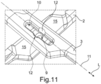
- FIG. 1 to 7 relate to a first embodiment and the Figures 1, 2 , 6 and 9 to 11 a second embodiment of the instrument according to the invention. How in particular a comparison of Figures 3 9 and 4 with 10, the first and second embodiments differ in that in the first embodiment a transverse groove 16 is formed in the first instrument branch 2, while such a transverse groove is not present in the second embodiment.
- the following description applies to both the first and second embodiments unless otherwise specified.
- the scissors or forceps-like medical instrument 1 shown as an example in the figures has a first instrument branch (instrument part) 2 and a second instrument branch (instrument part) 3 both in the first embodiment and in the second embodiment.
- the first instrument branch 2 has a first coupling/closing section 4.
- the second instrument branch 3 has a second coupling/closing section 5.
- the two instrument branches 2, 3 are coupled to one another in what is known as a closed circuit, i.e. they are on top of each other ( not inside each other) arranged so that the one, first instrument branch 2 rests on the other, second instrument branch 3 (on one side).
- the two instrument branches 2 , 3 are coupled to one another by a bearing element 6 .
- the bearing element 6 is in a sectional view in the Figures 5 and 6 shown. It is designed as a bearing pin 6 and has an essentially cylindrical pin section 7 on the one hand and an axially adjoining, widening conical head 8 on its axial side opposite the pin section 7 . According to the invention, it is designed without a thread and is fixed directly to the first instrument branch 2 with its pin section 7 .
- the pin section 7 is preferably cut into an in figure 7 recognizable passage opening / bore 9 of the first instrument branch 2 introduced.
- the pin section 7 can be connected to the first instrument branch 2 in a non-positive manner, for example pressed, riveted, caulked or clamped, or connected in a materially bonded manner, in particular glued, soldered or welded. In the present exemplary embodiment, it is pressed into the through opening 9 and riveted at the end on the side facing away from the second instrument branch 3 and formed into a rivet head 23 (in addition to the conical head 8). There is a gap-free interference fit between the through opening 9 and the pin section 7 .
- a through opening 10 in the second instrument branch 3 is designed as a slot 10 . Its longitudinal course 11 extends in the longitudinal direction L of the second instrument branch 3.
- the through-opening 10 is conically designed such that it widens conically in a section 12 with increasing distance from its side facing the first instrument branch 2.
- the conical section 12 forms a receiving recess 12 corresponding to the shape of the head 8 of the bearing pin 6 for this.
- the receiving recess 12 is not only conical, but also widens in the radial direction compared to the width A of the elongated hole 10 .
- the conical head 8 of the bearing element 6 widens as the distance from the first instrument branch 2 or as the distance from the bearing pin 7 increases. He penetrates the in figure 7 easily recognizable conically flared Through opening 10 of the second instrument branch 3 and is in (flat) contact with the widened receiving recess 12 .
- the conical outer surface 18 of the head 8 and the conical inner surface 19 of the receiving recess 12 form slide bearing surfaces 18, 19 that slide against or against one another when the branches 2, 3 are pivoted.
- figure 5 shows that the slot 10 has a substantially cylindrical opening section 21 on its side facing the final section 5 (on the side facing the first instrument branch 2) which has play 22 in relation to the bearing element 6 and its head 8.
- the two instrument branches 2 , 3 can be pivoted relative to one another as a result of their coupling by means of the bearing element 6 .
- the instrument branches 2, 3 make contact in a working pivoting range via three contact surfaces 13, 14, 15 facing one another.
- a third contact surface 15 is formed in the first end section 4 of the first instrument branch 2 .
- the transverse groove 16 is formed in the second end section 5 of the second instrument branch 3 in such a way that one of the contact surfaces 13 , 14 is arranged on both sides of the transverse groove 16 .
- the instrument branches 2, 3 make contact via two mutually facing contact surfaces 13, 15.
- the second closing section 5 of the second instrument branch 3 only the first contact surface 13 is formed.
- the further contact surface 15 is formed in the first closing section 4 of the first instrument branch 2 .
- no transverse groove 16 is formed in the second end section 5 of the second instrument branch 3 .
- the two instrument branches 2, 3 lie in a working pivoting range with their respective contact surfaces 13 and 14 or 15 bearing and leading to one another.
- figure 3 indicates that the contact surfaces 13, 14 move in relation to the third contact surface 15 when the two instrument branches 2, 3 are pivoted relative to one another.
- the two instruments are guided towards one another and are in the working swivel range. If the contact surfaces 13, 14, 15 separate from one another, the instrument 1 is no longer in the working swivel range.
- the instrument 1 located in the working pivot range according to the first embodiment is in the figures 1 , 3 and 5 shown.
- the instrument 1 can be brought into a cleaning position outside of the working pivoting range.
- the instrument 1 located in its cleaning position is in the figures 2 , 4 , 6 and 7 shown.
- the transverse groove 16 of the first embodiment has a width (b) in the longitudinal direction L of the second instrument branch 3, which is at least equal to the width (B) of the first instrument branch 2 in its end section 4 transverse to its longitudinal direction.
- the width (b) of the transverse groove 16 is greater than the width (B) of the branch 2, see in particular in figure 4 .
- the transverse groove 16 has a depth T, see FIG figure 5 .
- the depth T of the transverse groove 16 is dimensioned such that the gap 17 is formed and present between the two end sections 4, 5 of the instrument branches 2, 3 in the cleaning position (and thus also between the contact surfaces 13, 14, 15).
- the depth T of the transverse groove 16 and the receiving recess 12 in the slot 10 are matched to one another in such a way that the conical head 8 can be detached from the receiving recess 12 .
- FIG 8 shows a known instrument 24, in which a closing screw 25 is screwed into one of the instrument branches 2 against the stop (collar) and is slightly stripped to secure it, as a result of which the thread turns 26 are cold-welded.
- the end screw 25 passes through a stepped bore 27 in the other instrument branch 3 and has a screw head 28 which comes to rest on the other instrument branch 3 and this in the direction of one Instrument branch 2 is pushing / tense.
- the course of the instrument 24 results (resulting from the tension of the instrument branches 2, 3 against each other) from the distance between the contact surface 29 of the screw head 28 and the contact surface 30 of one instrument branch 2 and the tolerances 31 of the stepped bore 27 of the other instrument branch 3. This is the screw connection overdetermined.
- the two instrument branches 2, 3 rest and guide one another both in a working pivoting range and in the cleaning position with their respective contact surfaces 13 and 15, respectively.
- the width of the head 8 is also greater than the width A of the slot 10, so that the bearing element 6 can be rotated in the receiving recess 12, but cannot be positioned translationally in the slot 10 in its longitudinal direction, i.e. it cannot move out of the receiving recess 12 .
- the two instrument branches 2, 3 are coupled to one another in a purely (exclusively) rotatable manner.
- One possibility for cleaning the contact surfaces 13, 14, 15 is that the elongated hole 10 virtually sweeps over them when the instrument branches 2, 3 are pivoted and these are accessible through the elongated hole 10 for cleaning.
Landscapes
- Health & Medical Sciences (AREA)
- Surgery (AREA)
- Life Sciences & Earth Sciences (AREA)
- Medical Informatics (AREA)
- Animal Behavior & Ethology (AREA)
- Engineering & Computer Science (AREA)
- Biomedical Technology (AREA)
- Heart & Thoracic Surgery (AREA)
- Veterinary Medicine (AREA)
- Molecular Biology (AREA)
- Nuclear Medicine, Radiotherapy & Molecular Imaging (AREA)
- General Health & Medical Sciences (AREA)
- Public Health (AREA)
- Pathology (AREA)
- Ophthalmology & Optometry (AREA)
- Surgical Instruments (AREA)
- Endoscopes (AREA)
Claims (13)
- Instrument (1) à usage médical de type ciseaux ou pinces comportant une première branche d'instrument (2), une seconde branche d'instrument (3) et un élément de support (6) couplant les branches d'instrument (2, 3) dans une entablure posée,dans lequel les deux branches d'instrument (2, 3) peuvent pivoter l'une par rapport à l'autre et entrent en contact mutuellement dans une zone de pivotement de travail par l'intermédiaire de surfaces de contact (13, 14, 15) tournées les unes vers les autres dans une section d'entablure (4, 5),de sorte que les branches d'instrument (2, 3) s'appuient l'une contre l'autre de manière supportée et guidée avec leurs surfaces de contact (13, 14, 15) respectives dans la zone de pivotement de travail,et les branches d'instrument (2, 3) peuvent être positionnées dans une position de nettoyage en dehors de la zone de pivotement de travail,dans lequel l'élément de support (6) est de préférence sans filetage et est fixé de manière solidaire au niveau d'une section d'extrémité directement sur la première branche d'instrument (2) et présente, au niveau de l'autre section d'extrémité, une tête (8) s'élargissant de manière conique en continu ou de manière conique étagée à une distance croissante par rapport à la première branche d'instrument (2), laquelle tête traverse une ouverture de passage (10) conique en continu ou étagée dans la seconde branche d'instrument (3), l'ouverture de passage (10) étant réalisée sous la forme d'un trou oblong (10),caractérisé en ce que l'élément de support (6) est reçu dans le trou oblong (10) de manière à pouvoir être positionné par rotation et de manière solidaire en translation, en particulier est reçu de manière solidaire en position dans la direction longitudinale (L) du trou oblong (10).
- Instrument selon la revendication 1, caractérisé en ce que le trou oblong (10) possède, de préférence dans sa section médiane longitudinale, un renflement ou une encoche (12), de préférence en outre circulaire, sur un flanc longitudinal du trou oblong ou de manière opposée sur les deux flancs longitudinaux du trou oblong, avec lequel ou lesquels l'élément de support (6) est en prise bloquant un déplacement le long du trou oblong (10).
- Instrument (1) selon la revendication 1 ou 2, caractérisé en ce que l'axe longitudinal du trou oblong (10) s'étend dans la direction longitudinale (L) de la seconde branche d'instrument (3) et en particulier le trou oblong (10), lorsque les branches d'instrument (2, 3) se trouvent dans la position de nettoyage, dans laquelle les branches d'instrument (2, 3) sont sensiblement perpendiculaires l'une à l'autre, fait saillie des deux côtés depuis la première branche d'instrument (2) dans le sens de la largeur.
- Instrument (1) selon la revendication 1, 2 ou 3, caractérisé en ce que la longueur du trou oblong (10) dans la direction longitudinale (L) est supérieure à la largeur (B) de la première branche d'instrument (2) et/ou la longueur du trou oblong (10) dans la direction longitudinale (L) est supérieure à la longueur des surfaces de contact (13, 14, 15) respectives dans la direction longitudinale (L).
- Instrument selon l'une des revendications précédentes,
caractérisé en ce que, lors d'un pivotement des branches d'instrument (2, 3), le trou oblong (10) couvre au moins 90 %, de préférence 95 % et de manière particulièrement préférée 100 % de la surface de contact (15) de la première branche d'instrument (2). - Instrument selon l'une des revendications précédentes,
caractérisé en ce que la zone de pivotement de travail s'étend d'un angle d'ouverture α entre les branches d'instrument (2, 3) de 0° jusqu'à un angle d'ouverture compris entre environ 50° et 40°, de préférence d'environ 45°, et/ou un angle d'ouverture α compris entre environ 50° et environ 95°, de préférence compris entre 60°et 90°, plus préférablement d'environ 90°, est présent entre les branches d'instrument (2, 3) dans la position de nettoyage. - Instrument (1) selon l'une des revendications précédentes,
caractérisé en ce que l'élément de support (6) est réalisé en tant que broche de support (6) comportant une section de broche (7) sensiblement cylindrique d'un côté et la tête (8) se raccordant à celle-ci, de préférence la section de broche (7) étant enfoncée dans une ouverture (9), en particulier une ouverture traversante (9), de la première branche d'instrument (2). - Instrument (1) selon la revendication 6, caractérisé en ce que la section de broche (7) est reliée à force à la première branche d'instrument (2), en particulier est comprimée, rivetée, matée ou serrée, ou est reliée par liaison de matière, en particulier est collée, brasée ou soudée, ou en particulier la section de broche (7) est reliée à la première branche d'instrument (2) par une liaison vissée, laquelle est de préférence serrée de manière commandée par couple.
- Instrument (1) selon l'une des revendications précédentes 2 à 8, caractérisé en ce que les renflements ou encoches (12) forment ensemble une section de réception (12) en forme de trou, dont la largeur est élargie par rapport à la largeur A du trou oblong (10), et l'autre section d'extrémité de l'élément de support (6) est reçue de manière à pouvoir être positionnée par rotation dans la section de réception (12) et présente un diamètre supérieur à la largeur A du trou oblong (10).
- Instrument (1) selon la revendication 9, caractérisé en ce que la section de réception (12) du trou oblong (10) est réalisée de manière conique en continu ou de manière conique étagée.
- Instrument (1) selon l'une des revendications précédentes,
caractérisé en ce que l'ouverture traversante (10) de la seconde branche d'instrument (3) présente, sur le côté tourné vers la section d'entablure (5), une section d'ouverture (21) sensiblement cylindrique, laquelle possède un jeu (22) par rapport à l'élément de support (6). - Instrument (1) selon l'une des revendications précédentes,
caractérisé en ce que la section d'entablure (5) d'au moins l'une des branches d'instrument (3) présente une rainure transversale (16) et, des deux côtés de la rainure transversale (16), respectivement une surface de contact (13, 14) pour la section d'entablure (4) de l'autre branche d'instrument (2), une fente (17) ou un jeu (17) étant présent entre les branches d'instrument (2, 3) dans une position de nettoyage en dehors de la zone de pivotement de travail, sans contact mutuel par l'intermédiaire des surfaces de contact (13, 14, 15). - Instrument (1) selon la revendication 12, caractérisé en ce que la rainure transversale (16) présente une largeur (b) dans la direction longitudinale (L) de la branche d'instrument (3) respective au moins égale à la largeur (B) de l'autre branche d'instrument (2) dans sa section d'entablure (4) transversalement à sa direction longitudinale (L), la largeur (b) de la rainure transversale (16) étant de préférence légèrement supérieure ou supérieure à la largeur (B) de la branche (3) et/ou la rainure transversale (16) présentant une profondeur (T) comprise entre environ 1,0 mm et environ 0,1 mm, de préférence comprise entre environ 0,7 mm et environ 0,3 mm, plus préférablement d'environ 0,5 mm.
Applications Claiming Priority (2)
| Application Number | Priority Date | Filing Date | Title |
|---|---|---|---|
| DE102017109125.4A DE102017109125A1 (de) | 2017-04-27 | 2017-04-27 | Chirurgisches Instrument der zwei Branchen-Bauart mit verbesserter Reinigungseignung |
| PCT/EP2018/060894 WO2018197679A1 (fr) | 2017-04-27 | 2018-04-27 | Instrument chirurgical de construction à deux branches avec facilité de nettoyage améliorée |
Publications (2)
| Publication Number | Publication Date |
|---|---|
| EP3614937A1 EP3614937A1 (fr) | 2020-03-04 |
| EP3614937B1 true EP3614937B1 (fr) | 2023-04-12 |
Family
ID=62111059
Family Applications (1)
| Application Number | Title | Priority Date | Filing Date |
|---|---|---|---|
| EP18722009.0A Active EP3614937B1 (fr) | 2017-04-27 | 2018-04-27 | Instrument chirurgical de construction à deux branches avec facilité de nettoyage améliorée |
Country Status (7)
| Country | Link |
|---|---|
| US (1) | US11369396B2 (fr) |
| EP (1) | EP3614937B1 (fr) |
| CN (1) | CN110740699B (fr) |
| DE (1) | DE102017109125A1 (fr) |
| ES (1) | ES2946601T3 (fr) |
| PL (1) | PL3614937T3 (fr) |
| WO (1) | WO2018197679A1 (fr) |
Families Citing this family (2)
| Publication number | Priority date | Publication date | Assignee | Title |
|---|---|---|---|---|
| DE102016116624A1 (de) * | 2016-09-06 | 2018-03-22 | Karl Leibinger Medizintechnik Gmbh & Co. Kg | Medizinisches Instrument mit Reinigungsspalt im Verschlussbereich |
| GB2636051A (en) * | 2023-11-03 | 2025-06-11 | Endomagnetics Ltd | Improvements in and relating to the manufacture of handheld jointed instruments |
Family Cites Families (14)
| Publication number | Priority date | Publication date | Assignee | Title |
|---|---|---|---|---|
| US590528A (en) * | 1897-09-21 | Surgeon s scissors | ||
| DE29712016U1 (de) | 1997-07-08 | 1997-09-18 | >>Dovo<< Stahlwaren Bracht GmbH & Co KG, 42719 Solingen | Mehrzweckschere |
| DE10101425B4 (de) * | 2001-01-13 | 2005-09-08 | Aesculap Ag & Co. Kg | Chirurgisches Instrument |
| DE20100589U1 (de) | 2001-01-13 | 2001-05-03 | Aesculap AG & Co. KG, 78532 Tuttlingen | Chirurgisches Instrument |
| DE10221321A1 (de) * | 2002-05-07 | 2003-11-27 | Aesculap Ag & Co Kg | Schere für medizinische Zwecke |
| CN2595540Y (zh) * | 2003-01-30 | 2003-12-31 | 佘少芳 | 分离式剪刀 |
| JP2005204997A (ja) * | 2004-01-23 | 2005-08-04 | Olympus Corp | 医療器械 |
| DE202004002560U1 (de) | 2004-02-19 | 2004-04-22 | Helmut Zepf Medizintechnik Gmbh | Dentalmedizinische Zange |
| SE531737C2 (sv) * | 2006-12-01 | 2009-07-28 | Sundtorp Innovation Ab | Skruvlås för isärtagbara kirurgiska instrument |
| DE202010010843U1 (de) * | 2010-07-29 | 2010-11-04 | Richard Martin Medizintechnik Gmbh | Medizinisches Handwerkzeug |
| DE202011107977U1 (de) | 2011-11-17 | 2011-11-30 | Innovations-Medical Gmbh | Medizinisches Instrument |
| CN202723937U (zh) * | 2012-08-06 | 2013-02-13 | 刘�东 | 一种手术剪刀 |
| CN203436369U (zh) * | 2013-09-17 | 2014-02-19 | 中国人民解放军第二军医大学 | 一次性多功能医用剪刀 |
| DE202013010321U1 (de) | 2013-11-14 | 2014-01-15 | Innovations-Medical Gmbh | Zangenartiges medizinisches Instrument |
-
2017
- 2017-04-27 DE DE102017109125.4A patent/DE102017109125A1/de not_active Withdrawn
-
2018
- 2018-04-27 US US16/608,544 patent/US11369396B2/en active Active
- 2018-04-27 EP EP18722009.0A patent/EP3614937B1/fr active Active
- 2018-04-27 CN CN201880037207.2A patent/CN110740699B/zh active Active
- 2018-04-27 WO PCT/EP2018/060894 patent/WO2018197679A1/fr not_active Ceased
- 2018-04-27 PL PL18722009.0T patent/PL3614937T3/pl unknown
- 2018-04-27 ES ES18722009T patent/ES2946601T3/es active Active
Also Published As
| Publication number | Publication date |
|---|---|
| US20200197034A1 (en) | 2020-06-25 |
| WO2018197679A1 (fr) | 2018-11-01 |
| PL3614937T3 (pl) | 2023-07-24 |
| CN110740699B (zh) | 2023-07-25 |
| ES2946601T3 (es) | 2023-07-21 |
| US11369396B2 (en) | 2022-06-28 |
| CN110740699A (zh) | 2020-01-31 |
| EP3614937A1 (fr) | 2020-03-04 |
| DE102017109125A1 (de) | 2018-10-31 |
Similar Documents
| Publication | Publication Date | Title |
|---|---|---|
| DE2061539C3 (de) | Zange fur medizinische Zwecke und Verfahren zu deren Herstellung | |
| EP2874548B1 (fr) | Instrument endoscopique | |
| DE60015636T2 (de) | Kompressionsknochenschraube und Hilfsinstrumente zu ihrer Befestigung | |
| DE10319430B4 (de) | Vorrichtung zum Spreizen von Gewebe | |
| EP1879721B1 (fr) | Pince | |
| EP2594210B1 (fr) | Instrument médical | |
| EP3595548B1 (fr) | Instrument médical fabriqué par addition et procédé de fabrication d'un tel instrument | |
| DE102009006689A1 (de) | Chirurgisches Instrument | |
| DE202013010321U1 (de) | Zangenartiges medizinisches Instrument | |
| EP1566151B1 (fr) | Forceps dentaire composé de deux moitiés séparables | |
| EP3261566B1 (fr) | Plaque d'ostéosynthèse et kit chirurgical pour la fixation de fragments osseux | |
| DE10231369B4 (de) | Koagulationsklemme | |
| EP2787903B1 (fr) | Instrument médical | |
| EP0928602A2 (fr) | Outil pour cisaillement d'implants | |
| DE19803418B4 (de) | Verfahren zum Ausbilden eines Gelenkmechanismus für eine endoskopische Zange | |
| EP3614937B1 (fr) | Instrument chirurgical de construction à deux branches avec facilité de nettoyage améliorée | |
| WO2018046534A1 (fr) | Instrument médical présentant une fente de nettoyage dans la zone de verrouillage | |
| DE102009056099A1 (de) | Chirurgisches Instrument | |
| DE10317871B3 (de) | Osteosynthese-Vorrichtung | |
| EP2258290B1 (fr) | Clou huméral destiné au traitement de fractures de l'humérus | |
| DE102006016213A1 (de) | Chirurgische Verbindungsvorrichtung und chirurgische Vorrichtung | |
| DE102004056091B4 (de) | Orthopädische Fixationsvorrichtung und orthopädisches Fixationssystem | |
| EP2653122B1 (fr) | Outil pour un instrument médical | |
| EP1491155A1 (fr) | Instrument medical à tige coulissante, en particulier poinçonneuse à tissu | |
| DE102024134412B3 (de) | Chirurgisches Maulteilwerkzeug, chirurgisches Instrument und Herstellungsverfahren |
Legal Events
| Date | Code | Title | Description |
|---|---|---|---|
| STAA | Information on the status of an ep patent application or granted ep patent |
Free format text: STATUS: UNKNOWN |
|
| STAA | Information on the status of an ep patent application or granted ep patent |
Free format text: STATUS: THE INTERNATIONAL PUBLICATION HAS BEEN MADE |
|
| PUAI | Public reference made under article 153(3) epc to a published international application that has entered the european phase |
Free format text: ORIGINAL CODE: 0009012 |
|
| STAA | Information on the status of an ep patent application or granted ep patent |
Free format text: STATUS: REQUEST FOR EXAMINATION WAS MADE |
|
| 17P | Request for examination filed |
Effective date: 20191127 |
|
| AK | Designated contracting states |
Kind code of ref document: A1 Designated state(s): AL AT BE BG CH CY CZ DE DK EE ES FI FR GB GR HR HU IE IS IT LI LT LU LV MC MK MT NL NO PL PT RO RS SE SI SK SM TR |
|
| AX | Request for extension of the european patent |
Extension state: BA ME |
|
| RIN1 | Information on inventor provided before grant (corrected) |
Inventor name: VOGTHERR, ROBERT Inventor name: ETTWEIN, PIERRE |
|
| DAV | Request for validation of the european patent (deleted) | ||
| DAX | Request for extension of the european patent (deleted) | ||
| GRAP | Despatch of communication of intention to grant a patent |
Free format text: ORIGINAL CODE: EPIDOSNIGR1 |
|
| STAA | Information on the status of an ep patent application or granted ep patent |
Free format text: STATUS: GRANT OF PATENT IS INTENDED |
|
| INTG | Intention to grant announced |
Effective date: 20221024 |
|
| GRAS | Grant fee paid |
Free format text: ORIGINAL CODE: EPIDOSNIGR3 |
|
| GRAA | (expected) grant |
Free format text: ORIGINAL CODE: 0009210 |
|
| STAA | Information on the status of an ep patent application or granted ep patent |
Free format text: STATUS: THE PATENT HAS BEEN GRANTED |
|
| AK | Designated contracting states |
Kind code of ref document: B1 Designated state(s): AL AT BE BG CH CY CZ DE DK EE ES FI FR GB GR HR HU IE IS IT LI LT LU LV MC MK MT NL NO PL PT RO RS SE SI SK SM TR |
|
| REG | Reference to a national code |
Ref country code: GB Ref legal event code: FG4D Free format text: NOT ENGLISH |
|
| REG | Reference to a national code |
Ref country code: CH Ref legal event code: EP |
|
| REG | Reference to a national code |
Ref country code: DE Ref legal event code: R096 Ref document number: 502018011947 Country of ref document: DE |
|
| REG | Reference to a national code |
Ref country code: IE Ref legal event code: FG4D Free format text: LANGUAGE OF EP DOCUMENT: GERMAN |
|
| REG | Reference to a national code |
Ref country code: AT Ref legal event code: REF Ref document number: 1559374 Country of ref document: AT Kind code of ref document: T Effective date: 20230515 |
|
| REG | Reference to a national code |
Ref country code: NL Ref legal event code: FP |
|
| REG | Reference to a national code |
Ref country code: ES Ref legal event code: FG2A Ref document number: 2946601 Country of ref document: ES Kind code of ref document: T3 Effective date: 20230721 |
|
| REG | Reference to a national code |
Ref country code: LT Ref legal event code: MG9D |
|
| PG25 | Lapsed in a contracting state [announced via postgrant information from national office to epo] |
Ref country code: SE Free format text: LAPSE BECAUSE OF FAILURE TO SUBMIT A TRANSLATION OF THE DESCRIPTION OR TO PAY THE FEE WITHIN THE PRESCRIBED TIME-LIMIT Effective date: 20230412 Ref country code: PT Free format text: LAPSE BECAUSE OF FAILURE TO SUBMIT A TRANSLATION OF THE DESCRIPTION OR TO PAY THE FEE WITHIN THE PRESCRIBED TIME-LIMIT Effective date: 20230814 Ref country code: NO Free format text: LAPSE BECAUSE OF FAILURE TO SUBMIT A TRANSLATION OF THE DESCRIPTION OR TO PAY THE FEE WITHIN THE PRESCRIBED TIME-LIMIT Effective date: 20230712 |
|
| P01 | Opt-out of the competence of the unified patent court (upc) registered |
Effective date: 20230927 |
|
| PG25 | Lapsed in a contracting state [announced via postgrant information from national office to epo] |
Ref country code: RS Free format text: LAPSE BECAUSE OF FAILURE TO SUBMIT A TRANSLATION OF THE DESCRIPTION OR TO PAY THE FEE WITHIN THE PRESCRIBED TIME-LIMIT Effective date: 20230412 Ref country code: LV Free format text: LAPSE BECAUSE OF FAILURE TO SUBMIT A TRANSLATION OF THE DESCRIPTION OR TO PAY THE FEE WITHIN THE PRESCRIBED TIME-LIMIT Effective date: 20230412 Ref country code: LT Free format text: LAPSE BECAUSE OF FAILURE TO SUBMIT A TRANSLATION OF THE DESCRIPTION OR TO PAY THE FEE WITHIN THE PRESCRIBED TIME-LIMIT Effective date: 20230412 Ref country code: IS Free format text: LAPSE BECAUSE OF FAILURE TO SUBMIT A TRANSLATION OF THE DESCRIPTION OR TO PAY THE FEE WITHIN THE PRESCRIBED TIME-LIMIT Effective date: 20230812 Ref country code: HR Free format text: LAPSE BECAUSE OF FAILURE TO SUBMIT A TRANSLATION OF THE DESCRIPTION OR TO PAY THE FEE WITHIN THE PRESCRIBED TIME-LIMIT Effective date: 20230412 Ref country code: GR Free format text: LAPSE BECAUSE OF FAILURE TO SUBMIT A TRANSLATION OF THE DESCRIPTION OR TO PAY THE FEE WITHIN THE PRESCRIBED TIME-LIMIT Effective date: 20230713 |
|
| REG | Reference to a national code |
Ref country code: CH Ref legal event code: PL |
|
| PG25 | Lapsed in a contracting state [announced via postgrant information from national office to epo] |
Ref country code: LU Free format text: LAPSE BECAUSE OF NON-PAYMENT OF DUE FEES Effective date: 20230427 Ref country code: FI Free format text: LAPSE BECAUSE OF FAILURE TO SUBMIT A TRANSLATION OF THE DESCRIPTION OR TO PAY THE FEE WITHIN THE PRESCRIBED TIME-LIMIT Effective date: 20230412 |
|
| REG | Reference to a national code |
Ref country code: BE Ref legal event code: MM Effective date: 20230430 |
|
| REG | Reference to a national code |
Ref country code: DE Ref legal event code: R097 Ref document number: 502018011947 Country of ref document: DE |
|
| PG25 | Lapsed in a contracting state [announced via postgrant information from national office to epo] |
Ref country code: SK Free format text: LAPSE BECAUSE OF FAILURE TO SUBMIT A TRANSLATION OF THE DESCRIPTION OR TO PAY THE FEE WITHIN THE PRESCRIBED TIME-LIMIT Effective date: 20230412 |
|
| PG25 | Lapsed in a contracting state [announced via postgrant information from national office to epo] |
Ref country code: MC Free format text: LAPSE BECAUSE OF FAILURE TO SUBMIT A TRANSLATION OF THE DESCRIPTION OR TO PAY THE FEE WITHIN THE PRESCRIBED TIME-LIMIT Effective date: 20230412 |
|
| PG25 | Lapsed in a contracting state [announced via postgrant information from national office to epo] |
Ref country code: SM Free format text: LAPSE BECAUSE OF FAILURE TO SUBMIT A TRANSLATION OF THE DESCRIPTION OR TO PAY THE FEE WITHIN THE PRESCRIBED TIME-LIMIT Effective date: 20230412 Ref country code: SK Free format text: LAPSE BECAUSE OF FAILURE TO SUBMIT A TRANSLATION OF THE DESCRIPTION OR TO PAY THE FEE WITHIN THE PRESCRIBED TIME-LIMIT Effective date: 20230412 Ref country code: RO Free format text: LAPSE BECAUSE OF FAILURE TO SUBMIT A TRANSLATION OF THE DESCRIPTION OR TO PAY THE FEE WITHIN THE PRESCRIBED TIME-LIMIT Effective date: 20230412 Ref country code: MC Free format text: LAPSE BECAUSE OF FAILURE TO SUBMIT A TRANSLATION OF THE DESCRIPTION OR TO PAY THE FEE WITHIN THE PRESCRIBED TIME-LIMIT Effective date: 20230412 Ref country code: LI Free format text: LAPSE BECAUSE OF NON-PAYMENT OF DUE FEES Effective date: 20230430 Ref country code: EE Free format text: LAPSE BECAUSE OF FAILURE TO SUBMIT A TRANSLATION OF THE DESCRIPTION OR TO PAY THE FEE WITHIN THE PRESCRIBED TIME-LIMIT Effective date: 20230412 Ref country code: DK Free format text: LAPSE BECAUSE OF FAILURE TO SUBMIT A TRANSLATION OF THE DESCRIPTION OR TO PAY THE FEE WITHIN THE PRESCRIBED TIME-LIMIT Effective date: 20230412 Ref country code: CZ Free format text: LAPSE BECAUSE OF FAILURE TO SUBMIT A TRANSLATION OF THE DESCRIPTION OR TO PAY THE FEE WITHIN THE PRESCRIBED TIME-LIMIT Effective date: 20230412 Ref country code: CH Free format text: LAPSE BECAUSE OF NON-PAYMENT OF DUE FEES Effective date: 20230430 |
|
| REG | Reference to a national code |
Ref country code: IE Ref legal event code: MM4A |
|
| PLBE | No opposition filed within time limit |
Free format text: ORIGINAL CODE: 0009261 |
|
| STAA | Information on the status of an ep patent application or granted ep patent |
Free format text: STATUS: NO OPPOSITION FILED WITHIN TIME LIMIT |
|
| PG25 | Lapsed in a contracting state [announced via postgrant information from national office to epo] |
Ref country code: BE Free format text: LAPSE BECAUSE OF NON-PAYMENT OF DUE FEES Effective date: 20230430 |
|
| 26N | No opposition filed |
Effective date: 20240115 |
|
| PG25 | Lapsed in a contracting state [announced via postgrant information from national office to epo] |
Ref country code: IE Free format text: LAPSE BECAUSE OF NON-PAYMENT OF DUE FEES Effective date: 20230427 |
|
| PG25 | Lapsed in a contracting state [announced via postgrant information from national office to epo] |
Ref country code: IE Free format text: LAPSE BECAUSE OF NON-PAYMENT OF DUE FEES Effective date: 20230427 |
|
| PG25 | Lapsed in a contracting state [announced via postgrant information from national office to epo] |
Ref country code: SI Free format text: LAPSE BECAUSE OF FAILURE TO SUBMIT A TRANSLATION OF THE DESCRIPTION OR TO PAY THE FEE WITHIN THE PRESCRIBED TIME-LIMIT Effective date: 20230412 |
|
| PG25 | Lapsed in a contracting state [announced via postgrant information from national office to epo] |
Ref country code: SI Free format text: LAPSE BECAUSE OF FAILURE TO SUBMIT A TRANSLATION OF THE DESCRIPTION OR TO PAY THE FEE WITHIN THE PRESCRIBED TIME-LIMIT Effective date: 20230412 |
|
| REG | Reference to a national code |
Ref country code: AT Ref legal event code: MM01 Ref document number: 1559374 Country of ref document: AT Kind code of ref document: T Effective date: 20230427 |
|
| PG25 | Lapsed in a contracting state [announced via postgrant information from national office to epo] |
Ref country code: AT Free format text: LAPSE BECAUSE OF NON-PAYMENT OF DUE FEES Effective date: 20230427 |
|
| PG25 | Lapsed in a contracting state [announced via postgrant information from national office to epo] |
Ref country code: AT Free format text: LAPSE BECAUSE OF NON-PAYMENT OF DUE FEES Effective date: 20230427 |
|
| PG25 | Lapsed in a contracting state [announced via postgrant information from national office to epo] |
Ref country code: BG Free format text: LAPSE BECAUSE OF FAILURE TO SUBMIT A TRANSLATION OF THE DESCRIPTION OR TO PAY THE FEE WITHIN THE PRESCRIBED TIME-LIMIT Effective date: 20230412 |
|
| PG25 | Lapsed in a contracting state [announced via postgrant information from national office to epo] |
Ref country code: BG Free format text: LAPSE BECAUSE OF FAILURE TO SUBMIT A TRANSLATION OF THE DESCRIPTION OR TO PAY THE FEE WITHIN THE PRESCRIBED TIME-LIMIT Effective date: 20230412 |
|
| PGFP | Annual fee paid to national office [announced via postgrant information from national office to epo] |
Ref country code: NL Payment date: 20250422 Year of fee payment: 8 |
|
| PGFP | Annual fee paid to national office [announced via postgrant information from national office to epo] |
Ref country code: DE Payment date: 20250417 Year of fee payment: 8 Ref country code: PL Payment date: 20250411 Year of fee payment: 8 |
|
| PGFP | Annual fee paid to national office [announced via postgrant information from national office to epo] |
Ref country code: ES Payment date: 20250519 Year of fee payment: 8 |
|
| PGFP | Annual fee paid to national office [announced via postgrant information from national office to epo] |
Ref country code: IT Payment date: 20250430 Year of fee payment: 8 |
|
| PGFP | Annual fee paid to national office [announced via postgrant information from national office to epo] |
Ref country code: FR Payment date: 20250422 Year of fee payment: 8 |
|
| PG25 | Lapsed in a contracting state [announced via postgrant information from national office to epo] |
Ref country code: CY Free format text: LAPSE BECAUSE OF FAILURE TO SUBMIT A TRANSLATION OF THE DESCRIPTION OR TO PAY THE FEE WITHIN THE PRESCRIBED TIME-LIMIT; INVALID AB INITIO Effective date: 20180427 |
|
| PG25 | Lapsed in a contracting state [announced via postgrant information from national office to epo] |
Ref country code: HU Free format text: LAPSE BECAUSE OF FAILURE TO SUBMIT A TRANSLATION OF THE DESCRIPTION OR TO PAY THE FEE WITHIN THE PRESCRIBED TIME-LIMIT; INVALID AB INITIO Effective date: 20180427 |
|
| PG25 | Lapsed in a contracting state [announced via postgrant information from national office to epo] |
Ref country code: TR Free format text: LAPSE BECAUSE OF FAILURE TO SUBMIT A TRANSLATION OF THE DESCRIPTION OR TO PAY THE FEE WITHIN THE PRESCRIBED TIME-LIMIT Effective date: 20230412 |
|
| PGFP | Annual fee paid to national office [announced via postgrant information from national office to epo] |
Ref country code: GB Payment date: 20260324 Year of fee payment: 9 |