EP3615347B1 - Insert de sécurité pour un document d'identité et procédé de fabrication d'un insert de sécurité pour un document d'identité - Google Patents
Insert de sécurité pour un document d'identité et procédé de fabrication d'un insert de sécurité pour un document d'identité Download PDFInfo
- Publication number
- EP3615347B1 EP3615347B1 EP18718796.8A EP18718796A EP3615347B1 EP 3615347 B1 EP3615347 B1 EP 3615347B1 EP 18718796 A EP18718796 A EP 18718796A EP 3615347 B1 EP3615347 B1 EP 3615347B1
- Authority
- EP
- European Patent Office
- Prior art keywords
- layer
- transparent
- application
- transparent layer
- security
- Prior art date
- Legal status (The legal status is an assumption and is not a legal conclusion. Google has not performed a legal analysis and makes no representation as to the accuracy of the status listed.)
- Active
Links
Images


Classifications
-
- B—PERFORMING OPERATIONS; TRANSPORTING
- B42—BOOKBINDING; ALBUMS; FILES; SPECIAL PRINTED MATTER
- B42D—BOOKS; BOOK COVERS; LOOSE LEAVES; PRINTED MATTER CHARACTERISED BY IDENTIFICATION OR SECURITY FEATURES; PRINTED MATTER OF SPECIAL FORMAT OR STYLE NOT OTHERWISE PROVIDED FOR; DEVICES FOR USE THEREWITH AND NOT OTHERWISE PROVIDED FOR; MOVABLE-STRIP WRITING OR READING APPARATUS
- B42D25/00—Information-bearing cards or sheet-like structures characterised by identification or security features; Manufacture thereof
- B42D25/30—Identification or security features, e.g. for preventing forgery
- B42D25/305—Associated digital information
-
- B—PERFORMING OPERATIONS; TRANSPORTING
- B42—BOOKBINDING; ALBUMS; FILES; SPECIAL PRINTED MATTER
- B42D—BOOKS; BOOK COVERS; LOOSE LEAVES; PRINTED MATTER CHARACTERISED BY IDENTIFICATION OR SECURITY FEATURES; PRINTED MATTER OF SPECIAL FORMAT OR STYLE NOT OTHERWISE PROVIDED FOR; DEVICES FOR USE THEREWITH AND NOT OTHERWISE PROVIDED FOR; MOVABLE-STRIP WRITING OR READING APPARATUS
- B42D25/00—Information-bearing cards or sheet-like structures characterised by identification or security features; Manufacture thereof
- B42D25/30—Identification or security features, e.g. for preventing forgery
-
- B—PERFORMING OPERATIONS; TRANSPORTING
- B42—BOOKBINDING; ALBUMS; FILES; SPECIAL PRINTED MATTER
- B42D—BOOKS; BOOK COVERS; LOOSE LEAVES; PRINTED MATTER CHARACTERISED BY IDENTIFICATION OR SECURITY FEATURES; PRINTED MATTER OF SPECIAL FORMAT OR STYLE NOT OTHERWISE PROVIDED FOR; DEVICES FOR USE THEREWITH AND NOT OTHERWISE PROVIDED FOR; MOVABLE-STRIP WRITING OR READING APPARATUS
- B42D25/00—Information-bearing cards or sheet-like structures characterised by identification or security features; Manufacture thereof
- B42D25/20—Information-bearing cards or sheet-like structures characterised by identification or security features; Manufacture thereof characterised by a particular use or purpose
- B42D25/23—Identity cards
-
- B—PERFORMING OPERATIONS; TRANSPORTING
- B42—BOOKBINDING; ALBUMS; FILES; SPECIAL PRINTED MATTER
- B42D—BOOKS; BOOK COVERS; LOOSE LEAVES; PRINTED MATTER CHARACTERISED BY IDENTIFICATION OR SECURITY FEATURES; PRINTED MATTER OF SPECIAL FORMAT OR STYLE NOT OTHERWISE PROVIDED FOR; DEVICES FOR USE THEREWITH AND NOT OTHERWISE PROVIDED FOR; MOVABLE-STRIP WRITING OR READING APPARATUS
- B42D25/00—Information-bearing cards or sheet-like structures characterised by identification or security features; Manufacture thereof
- B42D25/20—Information-bearing cards or sheet-like structures characterised by identification or security features; Manufacture thereof characterised by a particular use or purpose
- B42D25/24—Passports
-
- B—PERFORMING OPERATIONS; TRANSPORTING
- B42—BOOKBINDING; ALBUMS; FILES; SPECIAL PRINTED MATTER
- B42D—BOOKS; BOOK COVERS; LOOSE LEAVES; PRINTED MATTER CHARACTERISED BY IDENTIFICATION OR SECURITY FEATURES; PRINTED MATTER OF SPECIAL FORMAT OR STYLE NOT OTHERWISE PROVIDED FOR; DEVICES FOR USE THEREWITH AND NOT OTHERWISE PROVIDED FOR; MOVABLE-STRIP WRITING OR READING APPARATUS
- B42D25/00—Information-bearing cards or sheet-like structures characterised by identification or security features; Manufacture thereof
- B42D25/30—Identification or security features, e.g. for preventing forgery
- B42D25/324—Reliefs
-
- B—PERFORMING OPERATIONS; TRANSPORTING
- B42—BOOKBINDING; ALBUMS; FILES; SPECIAL PRINTED MATTER
- B42D—BOOKS; BOOK COVERS; LOOSE LEAVES; PRINTED MATTER CHARACTERISED BY IDENTIFICATION OR SECURITY FEATURES; PRINTED MATTER OF SPECIAL FORMAT OR STYLE NOT OTHERWISE PROVIDED FOR; DEVICES FOR USE THEREWITH AND NOT OTHERWISE PROVIDED FOR; MOVABLE-STRIP WRITING OR READING APPARATUS
- B42D25/00—Information-bearing cards or sheet-like structures characterised by identification or security features; Manufacture thereof
- B42D25/30—Identification or security features, e.g. for preventing forgery
- B42D25/328—Diffraction gratings; Holograms
-
- B—PERFORMING OPERATIONS; TRANSPORTING
- B42—BOOKBINDING; ALBUMS; FILES; SPECIAL PRINTED MATTER
- B42D—BOOKS; BOOK COVERS; LOOSE LEAVES; PRINTED MATTER CHARACTERISED BY IDENTIFICATION OR SECURITY FEATURES; PRINTED MATTER OF SPECIAL FORMAT OR STYLE NOT OTHERWISE PROVIDED FOR; DEVICES FOR USE THEREWITH AND NOT OTHERWISE PROVIDED FOR; MOVABLE-STRIP WRITING OR READING APPARATUS
- B42D25/00—Information-bearing cards or sheet-like structures characterised by identification or security features; Manufacture thereof
- B42D25/30—Identification or security features, e.g. for preventing forgery
- B42D25/351—Translucent or partly translucent parts, e.g. windows
-
- B—PERFORMING OPERATIONS; TRANSPORTING
- B42—BOOKBINDING; ALBUMS; FILES; SPECIAL PRINTED MATTER
- B42D—BOOKS; BOOK COVERS; LOOSE LEAVES; PRINTED MATTER CHARACTERISED BY IDENTIFICATION OR SECURITY FEATURES; PRINTED MATTER OF SPECIAL FORMAT OR STYLE NOT OTHERWISE PROVIDED FOR; DEVICES FOR USE THEREWITH AND NOT OTHERWISE PROVIDED FOR; MOVABLE-STRIP WRITING OR READING APPARATUS
- B42D25/00—Information-bearing cards or sheet-like structures characterised by identification or security features; Manufacture thereof
- B42D25/30—Identification or security features, e.g. for preventing forgery
- B42D25/36—Identification or security features, e.g. for preventing forgery comprising special materials
- B42D25/378—Special inks
- B42D25/382—Special inks absorbing or reflecting infrared light
-
- B—PERFORMING OPERATIONS; TRANSPORTING
- B42—BOOKBINDING; ALBUMS; FILES; SPECIAL PRINTED MATTER
- B42D—BOOKS; BOOK COVERS; LOOSE LEAVES; PRINTED MATTER CHARACTERISED BY IDENTIFICATION OR SECURITY FEATURES; PRINTED MATTER OF SPECIAL FORMAT OR STYLE NOT OTHERWISE PROVIDED FOR; DEVICES FOR USE THEREWITH AND NOT OTHERWISE PROVIDED FOR; MOVABLE-STRIP WRITING OR READING APPARATUS
- B42D25/00—Information-bearing cards or sheet-like structures characterised by identification or security features; Manufacture thereof
- B42D25/30—Identification or security features, e.g. for preventing forgery
- B42D25/36—Identification or security features, e.g. for preventing forgery comprising special materials
- B42D25/378—Special inks
- B42D25/387—Special inks absorbing or reflecting ultraviolet light
-
- B—PERFORMING OPERATIONS; TRANSPORTING
- B42—BOOKBINDING; ALBUMS; FILES; SPECIAL PRINTED MATTER
- B42D—BOOKS; BOOK COVERS; LOOSE LEAVES; PRINTED MATTER CHARACTERISED BY IDENTIFICATION OR SECURITY FEATURES; PRINTED MATTER OF SPECIAL FORMAT OR STYLE NOT OTHERWISE PROVIDED FOR; DEVICES FOR USE THEREWITH AND NOT OTHERWISE PROVIDED FOR; MOVABLE-STRIP WRITING OR READING APPARATUS
- B42D25/00—Information-bearing cards or sheet-like structures characterised by identification or security features; Manufacture thereof
- B42D25/40—Manufacture
- B42D25/405—Marking
- B42D25/41—Marking using electromagnetic radiation
-
- B—PERFORMING OPERATIONS; TRANSPORTING
- B42—BOOKBINDING; ALBUMS; FILES; SPECIAL PRINTED MATTER
- B42D—BOOKS; BOOK COVERS; LOOSE LEAVES; PRINTED MATTER CHARACTERISED BY IDENTIFICATION OR SECURITY FEATURES; PRINTED MATTER OF SPECIAL FORMAT OR STYLE NOT OTHERWISE PROVIDED FOR; DEVICES FOR USE THEREWITH AND NOT OTHERWISE PROVIDED FOR; MOVABLE-STRIP WRITING OR READING APPARATUS
- B42D25/00—Information-bearing cards or sheet-like structures characterised by identification or security features; Manufacture thereof
- B42D25/40—Manufacture
- B42D25/45—Associating two or more layers
- B42D25/455—Associating two or more layers using heat
-
- B—PERFORMING OPERATIONS; TRANSPORTING
- B42—BOOKBINDING; ALBUMS; FILES; SPECIAL PRINTED MATTER
- B42D—BOOKS; BOOK COVERS; LOOSE LEAVES; PRINTED MATTER CHARACTERISED BY IDENTIFICATION OR SECURITY FEATURES; PRINTED MATTER OF SPECIAL FORMAT OR STYLE NOT OTHERWISE PROVIDED FOR; DEVICES FOR USE THEREWITH AND NOT OTHERWISE PROVIDED FOR; MOVABLE-STRIP WRITING OR READING APPARATUS
- B42D25/00—Information-bearing cards or sheet-like structures characterised by identification or security features; Manufacture thereof
- B42D25/40—Manufacture
- B42D25/45—Associating two or more layers
- B42D25/46—Associating two or more layers using pressure
-
- G—PHYSICS
- G06—COMPUTING OR CALCULATING; COUNTING
- G06K—GRAPHICAL DATA READING; PRESENTATION OF DATA; RECORD CARRIERS; HANDLING RECORD CARRIERS
- G06K19/00—Record carriers for use with machines and with at least a part designed to carry digital markings
- G06K19/06—Record carriers for use with machines and with at least a part designed to carry digital markings characterised by the kind of the digital marking, e.g. shape, nature, code
- G06K19/067—Record carriers with conductive marks, printed circuits or semiconductor circuit elements, e.g. credit or identity cards also with resonating or responding marks without active components
- G06K19/07—Record carriers with conductive marks, printed circuits or semiconductor circuit elements, e.g. credit or identity cards also with resonating or responding marks without active components with integrated circuit chips
- G06K19/0723—Record carriers with conductive marks, printed circuits or semiconductor circuit elements, e.g. credit or identity cards also with resonating or responding marks without active components with integrated circuit chips the record carrier comprising an arrangement for non-contact communication, e.g. wireless communication circuits on transponder cards, non-contact smart cards or RFIDs
-
- G—PHYSICS
- G06—COMPUTING OR CALCULATING; COUNTING
- G06K—GRAPHICAL DATA READING; PRESENTATION OF DATA; RECORD CARRIERS; HANDLING RECORD CARRIERS
- G06K19/00—Record carriers for use with machines and with at least a part designed to carry digital markings
- G06K19/06—Record carriers for use with machines and with at least a part designed to carry digital markings characterised by the kind of the digital marking, e.g. shape, nature, code
- G06K19/067—Record carriers with conductive marks, printed circuits or semiconductor circuit elements, e.g. credit or identity cards also with resonating or responding marks without active components
- G06K19/07—Record carriers with conductive marks, printed circuits or semiconductor circuit elements, e.g. credit or identity cards also with resonating or responding marks without active components with integrated circuit chips
- G06K19/077—Constructional details, e.g. mounting of circuits in the carrier
- G06K19/07749—Constructional details, e.g. mounting of circuits in the carrier the record carrier being capable of non-contact communication, e.g. constructional details of the antenna of a non-contact smart card
- G06K19/07773—Antenna details
Definitions
- a security insert for an identification document with optically recognizable characters is described here.
- Such security inserts can be used, for example, in passports in the form of a data sheet or in company ID cards, driver's licenses, ID cards, social security cards and membership cards.
- the security insert is suitable both for use in a booklet, for example a passport, and for an identification document in credit card format, for example according to ISO/IEC 7810.
- Such security inserts are typically substantially rectangular in plan view and include optically recognizable indicia such as personal photos, text fields, ID numbers, national insignia and/or emblems.
- the goals of using security deposits are the unique identifiability, durability, resilience and protection against forgery of the ID documents.
- security inserts for identity documents can be provided with visible features that are difficult or at least expensive to imitate. These features serve to make forgery of the identification documents more difficult and/or to distinguish genuine identification documents from forged identification documents.
- security inserts for identification documents can have security features which are invisible and/or visible only under certain conditions, for example under exposure to UV light. These features also serve to make forgery of the identification documents more difficult and/or to distinguish genuine identification documents from forged identification documents.
- the German patent shows DE 10 2013 218 861 A1 a semi-finished product for a security document, which reveals graphic information under UV excitation.
- the graphic information offers exclusively an optically recognizable security feature under UV excitation.
- the graphic information is transparent to light in the visible wavelength range.
- the European patent EP 2 004 415 B1 shows the use of laser engraving as a non-visible security feature for an identity document, but the document must be irreversibly destroyed in order to expose the laser engraving.
- the document comprises a first layer on which a security feature is arranged and a second layer which is connected to the first layer. Laser engravings are formed in the first layer.
- WO 2015/184556 A1 discloses a security element with an at least partially transparent multi-layer substrate on which three at least partially overlapping images are arranged.
- One of the layers may have a window in which two of the images are located.
- an identity card with a polymer carrier and a transparent plastic film arranged thereon is known.
- a color image is printed on the plastic film and a greyscale image is burned into the plastic film using a laser beam.
- the color image and the grayscale image are superimposed.
- the color image is transparent to infrared radiation.
- a clear laminate is provided to protect the color image.
- the object is therefore to provide an improved security insert for an identity document and a method for producing an improved security insert for an identity document. Unauthorized reproduction of the security deposit by third parties should be made more difficult and the integrity of the identification document should be able to be checked non-destructively by means of optically recognizable signs.
- a security insert with optically recognizable characters for an identity document comprises a first transparent layer and a second transparent layer. There is an application of paint on the first transparent layer. The application of paint is transparent to infrared light. The first transparent layer and the second transparent layer are connected to each other. At least one of the transparent layers has blackening. A first part of the optically recognizable characters is formed by the blackenings in at least one of the layers. A second part of the optically recognizable characters is formed by the application of paint. The first and second portions of the visually recognizable indicia are arranged and configured to reflect visible light. Infrared light is reflected by the first part of the optical characters.
- the security insert also has a layer of lacquer which is applied to the first transparent layer and/or to the application of paint.
- the lacquer layer is transparent to visible light and/or infrared light and/or UV light.
- the first layer of the security insert has an indentation, with the paint application being at least partially in the area of the indentation on the first layer and the indentation being filled with the lacquer layer, so that at least part of the paint application is enclosed by the first layer and the lacquer layer.
- the security insert thus shows first graphic information, which is formed jointly by the first part of the optically recognizable characters and the second part of the optically recognizable characters.
- the security insert shows a second piece of graphic information formed by the first part of the optical characters.
- the first graphic information and the second graphic information can be identical or different graphic information.
- a first image can be represented by the application of color on the first transparent layer, so that this image is optically recognizable during exposure to visible light.
- a second image which is in particular an image that differs from the first image, can be represented by blackening in at least one of the layers. This second image can be obscured by the first image so that it is not visually recognizable during exposure to visible light.
- the safety insert can only show the second image during the irradiation with infrared light.
- text information can also be represented by the blackening in at least one of the layers.
- a first image can be represented by the application of color on the first transparent layer and a second image can be represented by blackening in at least one of the layers, without the first image covering the second image.
- the first and the second image are thus visible during the irradiation with visible light and only the second image is visible during the irradiation with infrared light.
- a first image may be represented by the application of paint on the first transparent layer and a second image may be represented by blackening in at least one of the layers, the first and second images at least partially overlapping from the perspective of a viewer.
- the black components of an overall image can be formed by the blackening in at least one of the layers, while the color components of an image are formed by the application of paint, so that the overall image is visible during irradiation with visible light and only a partial image is visible during irradiation with infrared light is.
- a first part of a text or an image can be represented by the application of paint, in particular by a black or multicolored black application of paint that is transparent to infrared light, while a second part of the text or the image is represented by the blackening in at least one of the transparent layers is such that during the irradiation of the security insert with visible light all of the text or image is visible and during the irradiation of the security insert with infrared light only part of the text or image is visible.
- text containing information about the holder of the security deposit can be represented by omissions in the blackening in at least one of the transparent layers.
- at least one of the transparent layers has blackenings, which have omissions, in particular in the form of letters or other symbols, so that during the irradiation of the security insert with infrared light, the letters can be recognized by the fact that the blackenings reflect infrared light, but the omissions in the form of letters or other symbols do not reflect infrared light.
- the densities during the irradiation with infrared light show a negative image.
- the omissions and/or the blackenings surrounding them can be covered by a colored print, for example with a colorful black colored print transparent to infrared light, such that they are only visible under infrared light.
- One advantage of such a security insert is that the protection against forgery is increased and at the same time the authenticity of the security insert can be checked simply by irradiating it with infrared light.
- black portions of the optical sign can be formed both by blackening in at least one transparent layer and by black, in particular chromatic black, portions of the paint application, the creation of a copy of the Security deposit made considerably more difficult by unauthorized third parties.
- the color application can include color components from the original colors cyan, magenta and yellow.
- the application of color can be applied to the first transparent layer by means of an inkjet print.
- One advantage of using the color components from cyan, magenta and yellow is that, in one variant, the use of black color components to produce the color application can be at least partially dispensed with, without the available color spectrum being restricted as a result.
- Those black components of an overall image which are required in the printing methods known as the prior art (cyan-magenta-yellow-black printing method, CMYK printing method, according to ISO 2846) to create a true-color overall image, can be achieved by the blackening in at least one of the layers be educated.
- the use of black color components in the application of paint can be dispensed with, at least in part.
- a colorful black application can be formed, which is particularly transparent to infrared light.
- At least one of the transparent layers can be at least partially blackened by the action of at least one beam of laser light.
- the transparent layers can contain additives, in particular carbon-based additives.
- blackening, in particular charring can be produced in a desired intensity in a targeted manner.
- An advantage of using such blackenings in a security insert for an identity document is that an unauthorized third party who intends to counterfeit such a security insert cannot or only with difficulty determine which layer contains a specific blackening without destroying the security insert.
- the blackened areas can have different reflection properties than the color application, particularly when irradiated with infrared light, and thus further contribute to security against forgery and to the verifiability of the integrity of the security insert.
- the use of laser beams enables precise and time-efficient creation of the blackening.
- the security insert can include a first UV ink application, which is located on the first layer and/or on the ink application.
- the first UV ink application reflects at least UV light in a first wavelength range.
- a third part of the optically recognizable characters can be formed by the first application of UV ink.
- the security insert can further comprise a second UV ink application located on the first layer and/or on the ink application and/or on the first UV ink application.
- the second UV application of paint reflects at least UV light in a second wavelength range.
- a fourth part of the optically recognizable characters can be formed by the second application of UV ink.
- the third and/or the fourth part of the visually recognizable characters can show the same graphic information as the first and/or the second part of the visually recognizable characters and/or different graphic information from the first and/or second part of the visually recognizable characters. For example, a facial image of a security deposit holder may be shown.
- the first UV inking and/or the second UV inking may be transparent to visible light and/or infrared light.
- the first UV inking and/or the second UV inking can be multicolored UV inkings.
- the UV ink applications can have color components from red, green, blue and white (RGBW) or from cyan, magenta, yellow and/or black (CMYK), which each reflect UV light.
- RGBW red, green, blue and white
- CMYK cyan, magenta, yellow and/or black
- the use of further color components for the first and/or for the second UV color application is possible in a further development.
- the first UV ink application and/or the second UV ink application can be arranged and designed to show a viewer of the security insert multicolored graphic information during the irradiation of the security insert with UV light, for example a facial image of the ID card holder, which is displayed in particular during the irradiation of the safety insert with only visible light is not visible to the observer.
- the first and/or the second UV ink application can be bi-fluorescent.
- the first UV color application can give the observer of the security deposit a first color impression during the irradiation of the security deposit with UV light of a first wavelength and a second color impression during the irradiation of the security deposit with UV light of a third wavelength.
- the second UV color application can convey a third color impression to the observer of the security insert during the irradiation of the security insert with UV light of a second wavelength and convey a fourth color impression during the irradiation of the security insert with UV light of a fourth wavelength.
- the first, second, third and fourth color impression can each be different from one another or at least partially identical.
- the first UV color application can give the observer of the security insert a color impression from the color components red, green, blue and white during the irradiation of the security insert with UV light of a first wavelength of preferably 365 nm and during an irradiation of the security insert with UV Light of a third wavelength of preferably 254 nm convey a color impression from the color components green and red.
- the second UV color application can convey a blue color impression to the observer of the security insert during the irradiation of the security insert with UV light of a second wavelength of preferably 365 nm and during impart a red color impression to the security insert by irradiating it with UV light of a fourth wavelength of preferably 313 nm.
- first UV color application and/or the second UV color application are that further security features can be added to the security insert by creating a third and/or fourth part of the optical symbol, which are visible when the security insert is irradiated with UV light become. If both a first UV ink application and a second UV ink application are used, which each reflect UV light in different wavelength ranges, this makes it possible to further increase the counterfeit security of the security insert, in particular since replication of the security insert is made even more difficult.
- the security insert may further comprise a transparent cover sheet of polycarbonate, polyethylene terephthalate, or polyethylene terephthalate glycol.
- An advantage of the cover layer is the protection of the safety insert from negative environmental influences, such as the ingress of moisture, or protection from mechanical damage, such as the safety insert being scratched.
- the security insert described here also has a lacquer layer which is applied to the first transparent layer and/or to the application of paint.
- the lacquer layer can also be applied to the first and/or second UV paint application.
- the lacquer layer can completely cover a surface of the first transparent layer and an inking thereon or, in another example, only an inking on the first transparent layer and/or the first UV inking and/or the second UV inking cover.
- the lacquer layer can cover the paint application and/or the first UV paint application and/or the second UV paint application and part of the first transparent layer on the first transparent layer.
- the area covered by the lacquer layer can be 5 to 20 percent larger than the area of the inking and/or the first UV inking and/or the second UV inking located on the first transparent layer.
- the paint application and/or the first UV paint application and/or the second UV paint application can be completely enclosed/enclosed by the lacquer layer and the first transparent layer be so that the lacquer layer and the first transparent layer completely surround the inking and/or the first UV inking and/or the second UV inking in cooperation.
- the lacquer layer is transparent to visible light and/or infrared light and/or UV light.
- the lacquer layer can have a manufacturing material which is the same as a manufacturing material of the first transparent layer. At least part of the lacquer layer can have a manufacturing material made of (meth)acrylate, polyester acrylate or urethane acrylate.
- a production material of the lacquer layer can be, in particular, a thermally and/or UV-curable production material.
- the lacquer layer can have a thickness of less than 100 ⁇ m, for example a thickness of 12 ⁇ m to 80 ⁇ m. In particular, the lacquer layer can have a thickness of 30 ⁇ m to 80 ⁇ m. Furthermore, the lacquer layer can be applied to the first transparent layer by an inkjet printer. The temperature resistance of the lacquer layer can be greater than the temperature resistance of one of the transparent layers. In particular, the temperature resistance of the lacquer layer can be greater than the temperature resistance of the first transparent layer.
- the lacquer layer can optionally be applied to the first transparent layer in the form of a rectangle, a star or with the contour of a national emblem or coat of arms.
- the lacquer layer can be applied to the first transparent layer congruently with the contour of a facial image or enlarged in relation to the facial image.
- lacquer layer is that it cannot be removed from the first transparent layer, or can only be removed with difficulty, thus improving the counterfeit security of the security insert.
- the lacquer layer can protect the first transparent layer from scratches and/or from abrasion.
- the security insert can comprise a third transparent layer, in particular to be blackened by laser light, and/or a fourth transparent layer, in particular to be blackened by laser light.
- An advantage of further transparent layers, in particular those to be blackened by laser light, is a further increase in security against forgery.
- a totality of optically recognizable signs perceived from the perspective of an observer can thus be dislocated to a plurality of transparent layers as well as an inking and/or a plurality of UV inkings.
- At least one of the transparent layers can have an enlarged base area compared to another transparent layer, wherein the base area is to be understood as meaning the dimensions of the security insert or individual transparent layers from the perspective of an observer of the security insert.
- the enlarged base area of the at least one transparent layer can advantageously be used to connect the security insert to a booklet, in particular a passport. In this case, that part of the at least one transparent layer that is larger than another transparent layer can be used to attach the security insert in the booklet.
- a first background inking can be on the second layer.
- a second background color application can be on the fourth layer.
- An advantage of using background color applications is a contribution that can be produced efficiently to the optically perceptible overall information of the security insert.
- Both the first and the second background color application can contain security features which further increase the counterfeit security of the security insert.
- the first and/or the second background application can be created by an offset printing process.
- the security insert can comprise an inlay which has at least a first, in particular opaque and/or optically active, inlay layer.
- the inlay may be between the second and third transparent layers.
- the inlay can be located in a recess in the second and/or the third transparent layer.
- the inlay can comprise a second, in particular opaque and/or optically active, inlay layer.
- An arrangement of electronic components, in particular antenna modules and/or RFID chips, can be located between the first and the second inlay layer. Embodiments with further inlay layers are possible.
- One advantage of using an antenna module and/or an RFID chip is the further increase in security against forgery and the verifiability of the integrity of the Security deposit by electronic readout devices for RFID chips, which are known as prior art.
- At least one of the layers can comprise a hologram element which is visible to a viewer of the security insert and has a visual-holographic effect.
- the visual-holographic effect can be optically recognizable both under visible and under invisible light, in particular under infrared or ultraviolet light.
- the hologram element can be transparent to UV light.
- the hologram element can, at least from the perspective of an observer, at least partially overlap with some of the optically recognizable characters.
- the hologram element can also be arranged between the transparent layers or between a transparent layer and the inlay.
- the hologram element can be arranged between the first transparent layer and the second transparent layer or between the second transparent layer and the inlay.
- An advantage of using a hologram element is the further increase in security against forgery and the ability to check the integrity of the security insert.
- the transparent layers and/or the inlay and/or the cover layer can be connected to one another by lamination.
- One advantage of laminating the at least two transparent layers is that non-destructive separation of the layers from one another, for example for the production of a forgery of the security insert by an unauthorized third party, is made more difficult.
- At least one transparent layer of the security insert can be made of polycarbonate or polyethylene terephthalate.
- the security insert can be made entirely of polycarbonate or polyethylene terephthalate.
- the advantages of manufacturing the security insert from polycarbonate or polyethylene terephthalate result, for example, from the resistance, lightness and flexibility of the materials.
- the inking and/or the first UV inking and/or the second UV inking and/or the first background inking and/or the second background inking can be formed from solvent-based, in particular pigment-based, inks.
- the solvent-based, in particular pigment-based, inks can be suitable for dissolving and at least partially penetrating a surface made of polycarbonate or polyethylene terephthalate during an application process.
- One advantage of using such solvent-based inks to form the inking or background inking is an increase in the counterfeit security of the security deposits. For example, removal of the application of paint from the first transparent layer, for example for the purpose of replacing the first application of paint by an unauthorized third party, is made more difficult.
- the inking and/or the first UV inking and/or the second UV inking and/or the first background inking and/or the second background inking can contain forensic markers, in particular silicon, silicon dioxide, mica, titanium oxide and/or tin oxide.
- forensic markers An advantage of using such forensic markers is the verifiability of the integrity of a security deposit. Although such forensic markers are typically not visible to the naked eye, a targeted examination of the security deposit using the forensic markers can determine whether the document is an original or a forgery.
- the first transparent layer of the security insert has an indentation.
- the application of paint is at least partially in the depression.
- the first UV ink application and/or the second UV ink application can also be located at least partially in the region of the depression in the first transparent layer.
- the depression in the first transparent layer is filled with the lacquer layer, so that at least part of the paint application is enclosed by the first layer and the lacquer layer.
- the lacquer layer and/or at least one of the transparent layers can have an additive which reflects UV light in a first and/or in a second wavelength range.
- the lacquer layer and/or the transparent cover layer and/or at least one of the transparent layers can have nanoscale luminophores, which are designed to reflect UV light of a predetermined wavelength.
- the nanoscale luminophores, which are incorporated in the lacquer layer of the security insert reflect UV light of a predetermined wavelength, so that when the security insert is illuminated with UV light of the predetermined wavelength, part of the color application and/or the first UV color application and/or the second application of UV ink are hidden from an observer of the security insert.
- the indentation can be filled with the lacquer layer in such a way that it is flush with the surface of the first transparent layer, resulting in a planar overall surface without raised and/or lowered sections.
- One advantage of an indentation in which the inking and optionally the first UV inking and/or the second UV inking are at least partially enclosed by the first layer and a lacquer layer is an increase in counterfeit security, since non-destructive removal or replication of the Color application and optionally the first UV color application and/or the second UV color application by an unauthorized third party, for example for the purpose of counterfeiting the security deposit, is made considerably more difficult.
- the execution order of the steps is not fixed here.
- the second part of the optically recognizable characters can be created first and then the first part of the optically recognizable characters can be created.
- the layers can be connected by a lamination process.
- solvent-based, in particular pigment-based inks can be used that dissolve and at least partially penetrate a surface of the first layer, which is made in particular of polycarbonate or polyethylene terephthalate .
- the lacquer layer is applied to the first transparent layer while the application of paint, optionally also during the first UV application of paint and/or the second UV application of paint, is/are not yet completely dried/cured.
- One advantage here is improved adhesion or connection between the (UV) paint applications and the paint layer, so that non-destructive detachment of the paint layer from the first transparent layer with the paint applications is made even more difficult. As a result, the security of the insole can be further improved.
- the manufacturing device is characterized by a coating device which is arranged and configured to apply a layer of coating to the first transparent layer, the coating device also being arranged and configured to fill the depression in the first transparent layer with the layer of coating so that at least one Part of the application of paint is enclosed by the first layer and the varnish layer.
- the device for producing a security insert for an identification document with optically recognizable characters also optionally includes a laminating device.
- the laser device is designed and arranged to bring about blackening at least in a first and/or second transparent layer using a beam of laser light.
- the printing device is designed and arranged to apply an inking, and optionally a UV inking, to the first layer, which is transparent in particular to infrared light.
- the painting device is designed to apply the layer of paint to the first layer.
- the optional lamination device is designed and arranged to connect the cover layer to the first transparent layer.
- One advantage of the device for producing a security insert is that a ready-made security insert, for example in format ID 1 or format ID 3, can be personalized, in contrast to printing in sheet format, with a high degree of protection against counterfeiting by being printed, lasered and then is provided with a layer of lacquer.
- Figure 1A shows an example of a layer structure for a security insert 100 for an identity document.
- the layer structure can, for example, be as in Figure 1A shown include a cover layer 10, a first transparent layer 20, a second transparent layer 30, an inlay 40, a third transparent layer 50 and a fourth transparent layer 60.
- the inlay 40 is arranged between the second transparent layer 30 and the third transparent layer 50 so that it completely separates the second and the third transparent layer from one another and completely rests against the surfaces of the second transparent layer 30 and the third transparent layer 50 in each case.
- the inlay 40 is in the in Figure 1A example shown parallel to the transparent layers 20, 30, 50, 60 arranged.
- the security insert can be used in addition to or as an alternative to the Figure 1A cover layer 10 shown also include a printed lacquer layer (not shown).
- the lacquer layer is arranged analogously to the cover layer 10 and assumes its protective function for the surface of the security insert.
- a prefabricated first background inking 32 and a prefabricated second background inking 52 are as in FIG Figure 1A shown on the second transparent layer 30 and the third transparent layer 50.
- the first background color application 32 is on the surface of the second transparent layer 30 facing the cover layer 10.
- the second background color application 52 is on the side of the third transparent layer facing away from the cover layer 10 layer 50
- the first background inking 32 and the second background inking 52 are printed onto the second and third transparent layers 30, 50, respectively, by offset printing.
- the background application of color 32 is thus arranged between the application of color 22 and the blackening 34 .
- Figure 1B shows one Figure 1A alternative exemplary layer structure for a security insert 110 with optically recognizable characters for an identity document.
- the inlay 42 is designed and arranged to be located in a recess of the second transparent layer 30 and a recess of the third transparent layer 50 .
- the inlay 42 has a smaller extent in a cross section than the transparent layers enclosing the inlay.
- the inlay 40, 42 can comprise a single or a plurality of optically active, in particular transparent, inlay layers. If the inlay 40,42 also includes an antenna module and/or an RFID chip (not shown) in one variant, the inlay 40,42 must have at least two optically active inlay layers.
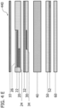
- Figure 2A shows an example of a layer structure for a security insert 200 with an application of paint 22.
- the application of paint 22 is located on the surface of the first transparent layer 20 facing the covering layer 10.
- the application of paint 22 is shown in the schematic drawing in a significantly exaggerated manner in order to be visible in cross section .
- the first transparent layer 20 and the application of paint 22 are protected by the covering layer 10 against negative environmental influences, for example the ingress of moisture or mechanical damage such as scratching.
- the application of color 22 is formed by a color print from the basic colors cyan, magenta and yellow. By combining the basic colors, a so-called chromatic black can also be formed, which is created by superimposing the basic colors. In one variant, the paint application 22 can also have black color components that are transparent to infrared light.
- the color application 22 is visible in front of the background color applications 32 and 52 for an observer who looks at the security insert 200 constructed from several layers from the direction of the cover layer 10 .
- Figure 2B shows a security insert 210 for an identification document with optically recognizable characters.
- the first transparent layer 20 shown has the blackenings 24.
- the first transparent layer 20, the second transparent layer 30, the third transparent layer 50 and the fourth transparent layer 60 are made of a polycarbonate material and contain carbon-containing additives which form the blackening under the influence of laser light in particular.
- the blackening in can be formed to a desired intensity by adjusting the intensity and exposure time of the laser light.
- the color application 22 which is formed from the basic colors cyan, magenta and yellow, and the blackening 24 complement each other, at least from the perspective of an observer, to form an overall picture.
- the black components of the overall image are formed here by the blackening in 24, so that the color application 22 does not have to contain any black components.
- the application of paint 22 can completely cover up the blackened areas 24 of the first transparent layer 20, at least from the viewer's perspective, so that only the application of paint 22 is visible to the viewer.
- a blackening 24 can be completely covered by a colorful black application of paint 22 .
- Figure 2C shows a security insert 220 for an identification document with optically recognizable characters.
- the second transparent layer 30 shown has the blackenings 34.
- the blackenings 34 shown are, at least from the perspective of the viewer, optically difficult or not at all different from those in Figure 2B shown blackenings 24 to distinguish.
- the manufacture and the properties of the blackenings 34 correspond to the blackenings 24 as in connection with FIG Figure 2B described. This applies analogously to blackenings in the third transparent layer 50 and/or the fourth transparent layer 60. (Not shown)
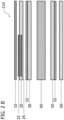
- Figure 2D shows a security insert 230 for an identity document with optically recognizable characters, which includes both blackening 24 in the first transparent layer 20 and blackening 34 in the second transparent layer 30.
- the blackenings are in different areas below the color imprint 22.
- the blackenings can overlay and/or complement one another from the viewer's perspective.
- Both the blackenings 24 and the blackenings 34 can make a contribution to the black component of an overall image, which an observer of the security insert perceives optically, and can also be partially or completely covered by the application of color 22 .
- the partial or complete optical concealment of the blackenings 24, 34 by the application of paint 22 from the perspective of the observer of the security insert can be brought about in particular by a colorful black part of the application of paint 22.
- An advantage of a security inlay 230 as shown in FIG. 2D is that it is difficult for an observer to determine in which transparent layer there is blackening without destroying the security inlay 230 . A counterfeiting of the security deposit is thus made more difficult.
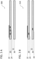
- FIG 3A shows a security insert 300 with optically recognizable characters for an identification document.
- the security insert shown comprises a first transparent layer 20 and a second transparent layer 30, each of which is made of polycarbonate with carbon-containing additives. There is an application of paint 22 on the first transparent layer 20.
- the first transparent layer 20 has a plurality of blackenings 24 which were formed in a targeted manner by the action of a beam of laser light on the carbon-containing additives contained in the first transparent layer 20 .
- those layers that do not have any blackening can also be made of polycarbonate without carbon-containing additives, for example.
- color 22 is on the surface of the first transparent layer 20 and is formed by a color print from the basic colors cyan, magenta and yellow. (The application of paint 22 is clearly exaggerated in the schematic drawing in order to be visible in cross section.)
- paint 22 and the blackening 24 complement one another, at least from the perspective of an observer, to form an overall picture.
- the black components of the overall image are formed here by the blackening 24.
- the blackenings 24 reflect both visible light and infrared light
- the blackenings 24 thus form a first part of the optically recognizable characters of the security insert 300 and the application of color 22 forms a second part of the optically recognizable characters of the security insert 300.
- the overall image formed jointly by the first part of the optically recognizable characters and the second part of the optically recognizable characters is visible to an observer during the irradiation of the security insert 300 with visible light.
- the security insert 300 with only infrared light only the first part of the optically recognizable characters is visible to an observer.
- Figure 3B shows a further development of the security insert 310 with optically recognizable characters for an identity document.
- the further development shown includes all the features described Figure 3A .
- the second transparent layer 30 also has at least one blackening 34 .
- the blackening 34 is formed by irradiating the second transparent layer 30 with laser light.
- the blackening 34 also supplements the application of paint 22, at least from the viewer's perspective, to form an overall picture.
- the black components of the overall image are displayed in the in Figure 3B shown variant formed both by the blackening 24 and by the blackening 34.
- the blackening 34 together with the blackening 24 forms the first part of the optically recognizable characters, which reflects both visible and infrared light.
- Figure 3C shows a further development of a security insert 320 with optically recognizable characters for an identity document.
- the further development shown includes all the features described Figures 3A and 3B .
- Figure 3C includes towards the Figures 3A and 3B furthermore a cover layer 10, an inlay 40, a third transparent layer 50, a fourth transparent layer 60, a first background color application 32 and a second background color application 52.
- the first background color application 32 is located on the surface of the second transparent layer 30 facing the covering layer 10.
- the second background color application 52 is located on the surface of the third transparent layer 50 facing away from the cover layer 10.
- a number of other background inkings may be located on the transparent layers and/or the inlay.
- the Figure 3C The cover layer 10 shown is transparent to visible light and/or infrared light, while the inlay 40 shown is opaque to visible and infrared light.
- one of the transparent layers 20, 30, 50, 60 and/or the inlay 40 can comprise a hologram element which is visible to a viewer of the security insert 320 and has a visual-holographic effect.
- the visual-holographic effect can be optically recognizable both under visible and under invisible light, in particular under infrared and/or ultraviolet light.
- the hologram element can be transparent to UV light.
- the hologram element can, at least from the perspective of an observer, at least partially overlap with some of the optically recognizable characters.
- the hologram element can also be arranged between the transparent layers 20, 30, 50, 60 and/or the inlay 40.
- the hologram element can be arranged between the first transparent layer 20 and the second transparent layer 30 or between the second transparent layer 30 and the inlay 40 .
- the inlay 40 is arranged between the second transparent layer 30 and the third transparent layer 50 so that it completely separates the second and the third transparent layer from one another and completely rests against the surfaces of the second transparent layer 30 and the third transparent layer 50 in each case.
- the inlay 40 is in the in Figure 3C example shown parallel to the transparent layers 20, 30, 50, 60 arranged.
- the inlay 40 can have at least two optically active inlay layers which enclose an RFID chip and/or an antenna element.
- FIGS. 4A and 4B show an example of a layer structure for a security insert 400, 410 with optically recognizable characters for an identification document with a recess.
- Safety inserts 400, 410 shown each comprise a first transparent layer 20 and a second transparent layer 30, which are each made of polycarbonate with carbon-containing additives.
- those layers that do not have any blackening can also be made of polycarbonate without carbon-containing additives, for example.
- the first transparent layer 20 shown has a depression.
- the depression can have a depth of 40-80 ⁇ m, for example.
- the second transparent layer 30 has the blackenings 34 which are located at least partially below the indentation from the perspective of an observer of the security insert 400 .
- the blackenings 34 are formed by the action of a beam of laser light on the additives containing carbon contained in the second transparent layer 30 .
- Figure 4B shows in addition to the in Figure 4A Features shown the application of paint 22, which is located in the recess of the first transparent layer 20.
- the application of color 22 is formed by a color print from the basic colors cyan, magenta and yellow.
- the application of paint does not protrude beyond the deepening. (The application of paint 22 is clearly exaggerated in the schematic drawing in order to be visible in cross section.)
- the contour of the indentation may be substantially adapted to the graphic information formed by the first part of the visually recognizable characters and the second part of the visually recognizable characters together.
- paint 22 which is formed from the basic colors cyan, magenta and yellow, and the blackenings 34 complement one another, at least from the perspective of an observer, to form an overall picture.
- the black portions of the overall image are formed here by the blackening in 34.
- the blackening in 34 reflect both visible light and infrared light.
- the blackenings 34 thus form a first part of the optically recognizable characters of the security insert 400, 410 and the application of color 22 forms a second part of the optically recognizable characters of the security insert 400, 410.
- Figure 4C shows an example of a layer structure for a security insert 420 with optically recognizable characters for an identity document with a depression that is filled with a polymer material.
- the polymer material can in particular be a paint material.
- Figure 4C contains all the features of Figures 4A and 4B .
- the polymer material 26 shown is transparent to visible and invisible, in particular ultraviolet or infrared, light and can be thermally cured.
- the polymer material can have an additive that reflects UV light in a first and/or in a second wavelength range, in particular color pigments that reflect UV light.
- the polymer material can contain forensic markers, in particular silicon, silicon dioxide, mica, titanium oxide and/or tin oxide.
- the polymeric material 26 located in the recess of the first transparent layer 20 is flush with the surface of the first transparent layer 20 so that the total surface of the first transparent layer 20 and the polymeric material 26 is a flat surface with no raised or lowered portions.
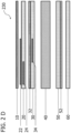
- Figure 4D shows an example of a layer structure for a security insert 430 with optically recognizable characters for an identity document with a depression that is filled with a polymer material.
- Figure 4D contains all the features of Figure 4C . Additionally shows Figure 4D the blackenings 24 in the first layer 20. The blackenings 24 in the first transparent layer 20 and the blackenings 34 in the second transparent layer 30 are located in different areas below the application of paint 22 from the perspective of the viewer.
- the blackenings can overlay and/or complement one another from the viewer's perspective.
- the blackenings 24 are formed by irradiating the first transparent layer 20 with laser light.
- Both the blackenings 24 and the blackenings 34 can make a contribution to the black component of an overall image, which an observer of the security insert perceives optically, and can also be partially or completely covered by the application of color 22 .
- the partial or complete optical concealment of the blackening 24, 34 by the application of paint 22 from the perspective of the observer of the security system can be brought about in particular by a part of the application of paint 22 that is colored black.
- Figure 4E shows a further development of a security insert 440 with optically recognizable characters for an identity document.
- the further development shown includes all the features described Figure 4D .
- Figure 4E includes towards the Figure 4D furthermore a cover layer 10, an inlay 40, a third transparent layer 50, a fourth transparent layer 60, a first background color application 32 and a second background color application 52.
- a transparent cover layer can be dispensed with.
- the first transparent layer can represent the outermost layer of the security insert.
- the first background application of color 32 is located on the surface of the second transparent layer 30 facing the cover layer 10.
- the first application of background color 32 is arranged between the application of color 22 and the blackening 34.
- the second background color application 52 is located on the surface of the third transparent layer 50 facing away from the covering layer 10.
- a number of other background inkings may be located on the transparent layers and/or the inlay.
- the recess can be filled with the lacquer material from which the lacquer layer is formed at the same time.
- the lacquer layer and the material that fills the recess can be formed in one piece in these embodiments and in particular introduced/applied into the recess or onto the first transparent layer by a printing process (not shown).
- the polymer material or paint material can have nanoscale luminophores which reflect UV light of a predetermined wavelength. If the security insert is illuminated with UV light of the predetermined wavelength, the UV light reflected by the polymer material or lacquer material (or by the luminophores contained therein) covers the paint application or the blackenings underneath for a viewer located visual signs.
- the cover layer 10 shown is transparent to visible light and infrared light, while the inlay 40 shown is opaque to visible light and infrared light.
- the inlay 40 is arranged between the second transparent layer 30 and the third transparent layer 50 so that it completely separates the second and the third transparent layer from one another and completely rests against the surfaces of the second transparent layer 30 and the third transparent layer 50 in each case.
- the inlay 40 is in the in Figure 4E illustrated embodiment parallel to the transparent layers 20, 30, 50, 60 arranged.
- one of the transparent layers 20, 30, 50, 60 and/or the inlay 40 can comprise a hologram element which is visible to a viewer of the security insert 440 and has a visual-holographic effect.
- the visual-holographic effect can be optically recognizable both under visible and under invisible light, in particular under infrared and/or ultraviolet light.
- the hologram element can, at least from the perspective of an observer, at least partially overlap with some of the optically recognizable characters.
- the hologram element can also be arranged between the transparent layers and/or the inlay.
- the hologram element can be arranged between the first transparent layer and the second transparent layer or between the second transparent layer and the inlay.
- the inlay 40 can have at least two opaque inlay layers which enclose an RFID chip and/or an antenna element.
- Figure 4F shows an alternative further development of the security insert 450 with optically recognizable characters for an identity document.
- the further development shown includes all the features described Figure 4E except for the inlay 40.
- the inlay shown is 42 designed and arranged to be located in a depression of the second transparent layer 30 and a depression of the third transparent layer 50.
- the inlay 42 has a smaller extent in a cross section than the transparent layers 30, 50 surrounding the inlay.
- Figure 5A shows a security insert 500 with optically recognizable characters for an identity document with a first UV ink application 28.
- Security insert 500 shown comprises a first transparent layer 20 and a second transparent layer 30, which are each made of polycarbonate with carbon-containing additives. There is an application of paint 22 on the first transparent layer 20.
- those layers that do not have any blackening can also be made of polycarbonate without carbon-containing additives, for example.
- the first transparent layer 20 has a plurality of blackenings 24 (only one blackening 24 is represented schematically), which were formed in a targeted manner by the action of a beam of laser light on the carbon-containing additives contained in the first transparent layer 20 .
- the application of paint 22 is located on the surface of the first transparent layer 20. (The application of paint 22 is shown significantly exaggerated in the schematic drawing in order to be visible in cross section.)
- the inking 22 may be transparent to UV light.
- the color application 22 which is formed from the basic colors cyan, magenta and yellow, and the blackening 24 complement each other, at least from the perspective of an observer, to form an overall picture.
- the black components of the overall image are formed here by the blackening 24 .
- the blackenings 24 thus form a first part of the optically recognizable characters of the security insert 500 and the application of color 22 forms a second part of the optically recognizable characters of the security insert 500.
- FIG 5A a first UV application of paint 28, which is on the application of paint 22.
- the first UV color application 28 is transparent to visible light and reflects UV light of a first wavelength and forms a third part of the optically recognizable characters of the security insert 500.
- the UV color application 28 is shown in the schematic drawing in a significantly exaggerated manner in order to be visible in cross section to be.
- the overall image formed jointly by the first part of the optically recognizable characters and the second part of the optically recognizable characters is visible to an observer during the irradiation of the security insert 500 with visible light.
- the third part of the optically recognizable characters is visible to an observer.
- Figure 5B shows a further development of the security insert 510 with optically recognizable characters for an identity document with a first UV ink application 28.
- the in Figure 5B The further development shown includes all the features described Figure 5A .
- the second transparent layer 30 also has at least one blackening 34 . Analogously to the blackenings 24, the blackening 34 is formed by irradiating the second transparent layer 30 with laser light.
- the blackened areas 34 of the second transparent layer 30 together with the blackened areas 24 of the first transparent layer 20 form the first part of the optically recognizable characters of the security insert 510.
- Blackenings 34 of the second transparent layer 30 shown are not covered by the application of paint 22 from the viewer's perspective.
- the blackened areas 34 of the second transparent layer 30 shown are analogous to the blackened areas 24 in the first transparent layer 20, but do not overlap with the application of paint 22.
- the blackened areas 34 of the second transparent layer 30 form the Figure 5B shown variant a separate optically recognizable sign consisting exclusively of blackening.
- FIG. 5B shows Figure 5B that a portion of the first UV ink application 28 is on the ink application 22 and a portion of the first UV ink application 28 is on the surface of the transparent layer 22.
- the third portion of the visual indicia formed by the UV ink application 28 only partially overlays the first and second portions of the visual indicia, respectively.
- FIGS. 5C and 5D show examples of further embodiments of a security insert 520, 530 with optically recognizable characters for an identification document with a first UV ink application 28.
- Figure 5C shows analogous to Figure 5A the first transparent layer 20, the blackening 24, a second transparent layer 30, the inking 22 and the first UV inking 28.
- a first part of the optically recognizable characters is formed by the blackening 24, a second part of the optically recognizable characters by the inking 22 and a third part of the optically recognizable characters is formed by the first UV inking 28.
- the third portion of the visually recognizable characters is superimposed on the first portion of the visually recognizable characters, while the second portion of the visually recognizable characters is not superimposed.
- a non-overlapping arrangement of the first and second portions of the optically recognizable indicia is visible to the viewer.
- a superimposed arrangement of the first, the second and the third part of the visual signs is visible.
- Figure 5D shows analogous to Figure 5A the first transparent layer 20, the blackening 24, a second transparent layer 30, the inking 22 and the first UV inking 28.
- a first part of the optically recognizable characters is formed by the blackening 24, a second part of the optically recognizable characters by the inking 22 and a third part of the optically recognizable characters is formed by the first UV inking 28.
- Blackenings 34 of the second transparent layer 30 shown are not covered by the application of paint 22 from the viewer's perspective.
- the shown blackenings 34 of the second transparent layer 30 are optically recognizable analogously to the blackenings 24 in the first transparent layer 20, but do not form an overall picture together with the application of paint 22.
- the blackenings 34 of the second transparent layer 30 form the in Figure 5D shown embodiment an optically recognizable sign formed exclusively from blackening.
- the observer can see an overlapping arrangement of the first and second parts of the optically recognizable characters and an arrangement of the first part of the optically recognizable characters that does not overlap with the second part of the optically recognizable characters .
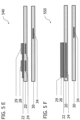
- the Figures 5E and 5F show one of the security inserts 540, 550 with optically recognizable characters for an identity document with a first UV ink application 28 and a second UV ink application 29.
- the in the Figures 5E and 5F Security insert 540, 550 shown comprises a first transparent layer 20 and a second transparent layer 30, each made of polycarbonate are manufactured with carbon-containing additives. On the first transparent layer 20 there is an application of paint 22.
- the first transparent layer 20 has a plurality of blackenings 24, which were formed by the action of a beam of laser light on the carbon-containing additives contained in the first transparent layer 20.
- the second transparent layer 30 has a plurality of blackenings 34 (only one blackening is shown schematically) which were formed by the action of a beam of laser light on the carbon-containing additives contained in the second transparent layer 30 .
- the application of paint 22 shown does not contain any black color components and reflects visible light and UV light.
- the application of paint 22 can be transparent to UV light and/or also have black color components that are transparent to infrared light.
- the color application 22 which is formed from the basic colors cyan, magenta and yellow, and the blackening 24 complement each other, at least from the perspective of an observer, to form an overall picture.
- the black components of the overall image are at least partially formed by the blackenings 24 .
- the blackened areas 24 and the blackened areas 34 form a first part of the optically recognizable characters of the security insert 540, 550 and the application of paint 22 forms a second part of the optically recognizable characters of the security insert.
- the blackenings 34 of the second transparent layer 30 are not covered by the application of paint 22 from the viewer's perspective.
- the shown blackenings 34 of the second transparent layer 30 are optically recognizable analogous to the blackenings 24 in the first transparent layer 20, but form a separate optically recognizable information which is spatially separated from the optically recognizable information which is visible to the viewer through the combination of the Blackening 24 with the application of color 22 is perceptible under visible light.
- the blackenings 34 can, for example, form optically recognizable text information (eg names, addresses, personal data) and in other embodiments (not shown) can be overlapped by the first and/or second UV ink application.
- the first UV color application 28 is transparent to visible light and reflects UV light of a first wavelength and forms a third part of the optically recognizable characters of the security insert 540, 550.
- Figures 5E and 5F a second UV inking 29 which is transparent to visible light and reflects UV light of a second wavelength.
- the second UV ink application 29 forms a fourth part of the optically recognizable characters of the security insert 540, 550.
- both the first UV ink application 28 and the second UV ink application 29 are each on a part of the ink application 22.
- the first UV ink application 28 and/or the second UV ink application 29 only partially overlap the application of paint 22.
- the first UV inking 28 is on the inking 22 and the second UV inking 29 is on the UV inking 28.
- security insert 540, 550 visible with visible light together formed by the first part of the optically recognizable characters and the second part of the optically recognizable characters overall image.
- first part of the visual characters that is not superimposed by the second part of the visual characters is also visible.
- the third part of the optically recognizable characters is visible to an observer.
- the fourth part of the optically recognizable characters is visible to an observer.
- Figure 5G shows a security insert 560 with the inking 22, the first UV inking 28 and the second UV inking 29.
- the first UV inking 28 and the second UV inking 29 are in Figure 5G multicolor UV paint jobs.
- the first UV inking 28 and inking 22 are on the first transparent layer 20.
- the second UV inking 29 is on the inking 28.
- the inking 22 reflects in the in Figure 5G shown embodiment visible light and UV light.
- embodiments of the security insert 560 are also possible in which the inking 22, the first UV inking 28 and the second UV inking 29 do not overlap, so that the inking 22, the first UV inking 28 and the second UV inking 29 are each applied directly to the first transparent layer 20 without superimposing one another.
- the third part of the optically recognizable characters formed by the first UV ink application 28 shows the observer of the security insert 560 during the irradiation of the security insert 560 with UV light of a first wavelength in the Figure 5G embodiment shown, for example, a facial image of a holder of security deposit 560.
- the facial image consisting of the first and the second part of the optically recognizable characters is visible.
- the facial image consisting of the first and the second part of the optically recognizable characters and additionally the same facial image consisting of the third part of the optically recognizable characters are visible.
- the facial images can thus be compared with one another, which makes it difficult for unauthorized persons to replace the historical image, for example.
- the second UV ink application 29 is in the in Figure 5G shown embodiment bi-fluorescent and forms a fourth part of the optically recognizable characters, which form additional security features.
- the second UV ink application 29 shows the observer of the security insert 560 a security feature with a red color impression.
- the security inlay 560 shows the viewer a security feature with a blue color impression.
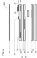
- figure 6 shows a security insert 600 with optically recognizable characters for an identification document with a recess, a first UV ink application and a second UV ink application.
- figure 6 shows a covering layer 10, a first transparent layer 20, a second transparent layer 30, an inlay 42, a third transparent layer 50 and a fourth transparent layer 60.
- the security insert can be used in addition to or as an alternative to the figure 6 cover layer 10 shown also include a printed lacquer layer (not shown).
- the lacquer layer is arranged analogously to the cover layer 10 and takes over its protective function for the surface of the security insert.
- the inlay 42 is located in a depression in the second transparent layer 30 and in a depression in the third transparent layer 50.
- the first transparent layer 20, the second transparent layer 30, the third transparent layer 50 and the fourth transparent layer 60 are made of a polycarbonate material and contain carbon-containing additives which form blackening under the influence of laser light in particular.
- the blackening in can be formed to a desired intensity by adjusting the intensity and exposure time of the laser light.
- the first transparent layer 20 has a plurality of blackenings 24 formed by exposure of the carbonaceous additives contained in the first transparent layer 20 to a beam of laser light.
- the second transparent layer 30 has a plurality of blackenings 34 (only one blackening is shown schematically) which were formed by the action of a beam of laser light on the carbon-containing additives contained in the second transparent layer 30 .
- one of the transparent layers 20, 30, 50, 60 and/or the inlay 40 can comprise a hologram element which is visible to a viewer of the security insert 440 and has a visual-holographic effect.
- the visual-holographic effect can be optically recognizable both under visible and under invisible light, in particular under infrared and/or ultraviolet light.
- the hologram element can, at least from the perspective of an observer, at least partially overlap with some of the optically recognizable characters.
- the hologram element can also be arranged between the transparent layers and/or the inlay.
- the hologram element can be arranged between the first transparent layer and the second transparent layer or between the second transparent layer and the inlay.
- the hologram element can at least partially overlap with the third and/or fourth part of the optically recognizable characters.
- the inlay 42 can have at least two opaque inlay layers which enclose an RFID chip and/or an antenna element.
- FIG 6 shows figure 6 a first background application 32 and a second background application 52.
- the first background application 32 is on the surface of the second transparent layer 30 facing the cover layer 10.
- the second background application 52 is on the surface of the third transparent layer 50 facing away from the cover layer 10.
- the first transparent layer 20 shown has a depression.
- the application of paint 22 is formed by a color print from the basic colors cyan, magenta and yellow.
- paint 22 shown has no black color components, is transparent to infrared light and reflects visible and ultraviolet light.
- the application of paint 22 and the blackenings 24, 34 complement one another, at least from the perspective of an observer, to form an overall picture.
- the black portions of the overall image are formed here by the blackenings 24, 34.
- the blackenings 24, 34 reflect both invisible, in particular ultraviolet and infrared, light and visible light.
- FIG. 6 shows figure 6 a polymeric material 26 located in the recess of the first transparent layer 20.
- the polymer material 26 shown is transparent to visible and invisible, in particular ultraviolet or infrared, light and can be thermally cured.
- the polymer material can have an additive that reflects UV light in a first and/or in a second wavelength range, in particular color pigments that reflect UV light.
- the polymer material can contain forensic markers, in particular silicon, silicon dioxide, mica, titanium oxide and/or tin oxide.
- the polymer material 26 located in the depression of the first transparent layer 20 is flush with the surface of the first transparent layer 20, so that the total surface of the first transparent layer 20 and the polymer material 26 forms a flat surface without any raised or lowered sections.
- FIG 6 shows figure 6 a first UV application of paint 28, which is on the application of paint 22.
- the first UV application of paint 28 is transparent to visible and infrared light and reflects UV light of a first wavelength.
- FIG 6 shows figure 6 a second UV inking 29 which is transparent to visible and infrared light and reflects UV light of a second wavelength.
- the second UV ink application 29 is located on the first UV ink application 28.
- the blackenings 24, 34 thus form a first part of the optically recognizable characters of the security insert 600 and the inking 22 forms a second part of the optically recognizable characters of the security insert 600.
- the first UV inking 28 forms a third part of the optically recognizable characters and the second UV inking 29 forms a fourth portion of the visually recognizable characters.
- the security insert 600 is irradiated with visible light, the first and the second part of the optically recognizable characters are visible to the observer, with the first and the second part of the optically recognizable characters partially overlap and thus form an overall picture.
- the security insert 600 is irradiated with infrared light, only the first part of the optically recognizable characters is visible to the viewer.
- the security insert 600 is irradiated with UV light of a first wavelength, the third part of the optically recognizable characters is visible.
- the security insert 600 is irradiated with UV light of a second wavelength, the fourth part of the optically recognizable characters is visible.
Landscapes
- Engineering & Computer Science (AREA)
- Manufacturing & Machinery (AREA)
- Physics & Mathematics (AREA)
- Computer Hardware Design (AREA)
- Theoretical Computer Science (AREA)
- General Physics & Mathematics (AREA)
- Microelectronics & Electronic Packaging (AREA)
- Computer Networks & Wireless Communication (AREA)
- Health & Medical Sciences (AREA)
- Toxicology (AREA)
- General Health & Medical Sciences (AREA)
- Electromagnetism (AREA)
- Credit Cards Or The Like (AREA)
- Printing Methods (AREA)
Claims (17)
- Un insert de sécurité (300, 310) avec des signes optiquement reconnaissables pour un document d'identité, comprenant :une première couche transparente (20), etune application de peinture (22) sur la première couche (20), etune deuxième couche transparente (30), dans laquellela première et la deuxième couche (20, 30) sont liées l'une à l'autre, etau moins l'une des couches (20, 30) présente des noircissements (24, 34), etla application de peinture (22) est transparente à la lumière infrarouge, etune première partie des signes optiquement reconnaissables est formée par les noircissements (24, 34) dans au moins une des couches (20, 30), etune deuxième partie des caractères optiquement reconnaissables est formée par l'application de peinture (22) de telle sorte quela première et la deuxième partie des signes optiquement reconnaissables réfléchissent la lumière visible et que la première partie des signes optiques réfléchit la lumière infrarouge,l'insert de sécurité comprenant en outre une couche de vernis qui est appliquée sur la première couche transparente (20) et/ou sur l'application de peinture (22),la couche de vernis étant transparente à la lumière visible et/ou à la lumière infrarouge et/ou à la lumière UV,caractérisé en ce queen ce que la première couche (20) présente un creux, l'application de peinture (22) se trouvant au moins partiellement dans la zone du creux sur la première couche (20), et le creux étant rempli par la couche de vernis, de sorte qu'au moins une partie de l'application de peinture (22) est entourée par la première couche (20) et la couche de vernis.
- L'insert de sécurité (320) pour un document d'identité selon la revendication 1, dans lequel
l'application de peinture (22) comprend différentes parties de couleur parmi le cyan, le magenta et le jaune. - L'insert de sécurité (320) pour un document d'identité selon la revendication 1 ou 2, dans lequel
au moins une des couches (20, 30) doit être noircie par l'action d'au moins un acier provenant d'une lumière laser. - L'insert de sécurité (320) pour un document d'identité selon l'une des revendications précédentes, caractérisé en ce queles noircissements (24, 34) présentent des omissions dans au moins une des couches (20, 30), oùles omissions ont notamment la forme de lettres qui sont entourées par les noircissements (24, 34).
- L'insert de sécurité (300, 310, 320) pour un document d'identité selon l'une quelconque des revendications précédentes, comprenant en outreune couche de couverture transparente (10), et/ouun inlay (40) qui comprend au moins une première couche d'inlay opaque, et/ouune troisième couche transparente (50), en particulier à noircir par lumière laser, et/ouune quatrième couche transparente (60), en particulier à noircir par lumière laser, et/ouune première application de couleur de fond (32) sur la deuxième couche (30), et/ouune deuxième couche de couleur de fond (52) se trouvant sur la troisième couche (50).
- L'insert de sécurité (300, 310, 320) pour un document d'identité selon la revendication 5, l'insert (40) étantune deuxième couche d'inlay opaque, et/ouun ensemble de composants électroniques, notamment un module d'antenne et/ou une puce RFID.
- L'insert de sécurité (300, 310, 320) pour un document d'identité selon la revendication 5 ou 6, dans lequelau moins une des couches (20, 30, 40, 50, 60) comprend un élément holographique, et/ou dans lequelau moins un élément holographique est disposé entre deux des couches transparentes (20, 30, 50, 60) ou entre une couche transparente (20, 30, 50, 60) et l'inlay (40), et/ou dans lequelau moins une couche transparente (20, 30, 50, 60) est reliée à une autre couche transparente (20, 30, 50, 60) et/ou à la couche de recouvrement (10) et/ou à l'inlay (40) par une stratification.
- L'insert de sécurité (300, 310, 320) pour un document d'identité selon l'une des revendications précédentes, caractérisé en ce que
au moins une couche est fabriquée en polycarbonate ou en polyéthylène téréphtalate. - L'insert de sécurité (300, 310, 320) pour un document d'identité selon l'une des revendications précédentes,
dans laquelleau moins une partie de la couche de vernis présente un matériau de fabrication en méthacrylate, en polyester acrylate ou en uréthane acrylate, et/oula couche de vernis présente un matériau de fabrication durcissable à la chaleur et/ou aux UV. - L'insert de sécurité (300, 310, 320) pour un document d'identité selon la revendication 9, caractérisé en ce que
la couche de vernis et/ou la couche de couverture transparente (10) et/ou au moins l'une des couches (20, 30, 40, 50, 60) présente(nt) des luminophores à l'échelle nanométrique qui sont conçus pour réfléchir la lumière UV d'une longueur d'onde prédéterminée. - L'insert de sécurité (300, 310, 320) pour un document d'identité selon l'une des revendications 9 ou 10, caractérisé en ce quela couche de vernis recouvre le application de peinture (22) et/ou un premier dépôt d'encre UV (28), de sorte quele application de peinture (22) et/ou le premier dépôt d'encre UV (28) sont complètement enfermés entre la première couche transparente (20) et la couche de vernis.
- L'insert de sécurité (300, 310, 320) pour un document d'identité selon l'une des revendications précédentes, caractérisé en ce quel'application de peinture (22) et/ou la première application de couleur de fond (32) et/ou la deuxième application de couleur de fond (52) sont formées d'encres contenant des solvants, en particulier à base de pigments, oùles encres contenant des solvants, en particulier à base de pigments, sont appropriées pour dissoudre et pénétrer au moins partiellement une surface en polycarbonate ou en polyéthylène téréphtalate pendant un processus d'application, et/oul'application de peinture (22) et/ou la première application d'encre de fond (32) et/ou la deuxième application d'encre de fond (52) contiennent des marqueurs médico-légaux, en particulier du silicium, du dioxyde de silicium, du mica, de l'oxyde de titane et/ou de l'oxyde d'étain.
- L'insert de sécurité (300, 310, 320) pour un document d'identité selon l'une des revendications précédentes.
dans laquelle
la couche de vernis contient un additif, en particulier des luminophores nanométriques, qui réfléchit la lumière UV. - Un procédé de fabrication d'un insert de sécurité (300, 310, 320) avec des signes optiquement reconnaissables pour un document d'identité, comprenant les étapes suivantes :- Préparation d'une première couche transparente (20),- Fournir une deuxième couche transparente (30),- Création d'une première partie des caractères optiquement reconnaissables par noircissement (22, 34) dans au moins une couche (20, 30) au moyen d'un faisceau de lumière laser,- création d'une deuxième partie des caractères optiques par application d'une application de peinture (22) sur la première couche (20),caractérisé par- Création d'un creux dans la première couche (20), notamment par enfoncement et/ou estampage et/ou fraisage,- remplissage du creux avec une couche de vernis, et- application de la couche de vernis sur la première couche transparente, alors que l'application de peinture (22) n'est pas encore complètement sèche ou durcie.
- Le procédé de fabrication d'un insert de sécurité (300, 310, 320) selon la revendication 14, dans lequelpour réaliser la application de peinture (22), on utilise des encres contenant des solvants, en particulier à base de pigments, quidissolvent et pénètrent au moins partiellement une surface de la première couche, qui est en particulier fabriquée en polycarbonate ou en polyéthylène téréphtalate, et/oules couches sont reliées entre elles par laminage.
- Le procédé de fabrication d'un insert de sécurité (300, 310, 320) selon la revendication 14 ou 15, comprenant en outre au moins une des étapes :- Fournir une couche de couverture (10),- Liaison de la première couche transparente (20) à la couche de couverture (10).
- Un dispositif pour la fabrication d'un insert de sécurité (300, 310, 320) avec des signes optiquement reconnaissables pour un document d'identité,
l'insert de sécurité (300, 310, 320) comprenant ce qui suit :une première couche transparente (20) qui présente un creux, etune application de peinture (22) se trouvant sur la première couche (20), l'application de peinture (22) se trouvant au moins partiellement dans la zone du creux sur la première couche (20), etune deuxième couche transparente (30), dans laquellela première et la deuxième couche (20, 30) sont reliées entre elles, etau moins une des couches (20, 30) présente des noircissements (24, 34), etla application de peinture (22) est transparente à la lumière infrarouge, etune première partie des signes optiquement reconnaissables est formée par les noircissements (24, 34) dans au moins une des couches (20, 30), etune deuxième partie des signes optiquement reconnaissables est formée par l'application de peinture (22) de telle sorte que la première et la deuxième partie des signes optiquement reconnaissables réfléchissent la lumière visible et que la première partie des signes optiquement reconnaissables réfléchit la lumière infrarouge, etla cavité est remplie par la couche de vernis, de sorte qu'au moins une partie de l'application de peinture (22) est entourée par la première couche (20) et la couche de vernis ;le dispositif comprenant ce qui suit :un dispositif laser agencé et conçu pour provoquer le noircissement d'une première et/ou d'une deuxième couche transparente (20, 30) par un faisceau de lumière laser, etun dispositif d'impression à jet d'encre, qui est agencé et conçu pour appliquer le application de peinture (22) sur la première couche transparente (20), de sorte que le application de peinture (22) se trouve au moins partiellement dans la zone de l'indentation sur la première couche (20), caractérisé parun dispositif de peinture, qui est agencé et conçu pour appliquer une couche de vernis sur la première couche transparente (20), dans lequelle dispositif de peinture est en outre agencé et conçu pour remplir le creux dans la première couche transparente avec la couche de vernis, de sorte qu'au moins une partie de l'application de peinture (22) est entourée par la première couche (20) et la couche de vernis.
Priority Applications (1)
| Application Number | Priority Date | Filing Date | Title |
|---|---|---|---|
| EP20193543.4A EP3760451B1 (fr) | 2017-04-26 | 2018-04-18 | Insert de sécurité pour un document d'identité et procédé de fabrication d'un insert de sécurité pour un document d'identification |
Applications Claiming Priority (3)
| Application Number | Priority Date | Filing Date | Title |
|---|---|---|---|
| DE102017004039.7A DE102017004039B4 (de) | 2017-04-26 | 2017-04-26 | Sicherheitseinlage für ein Ausweisdokument und Verfahren zur Herstellung einer Sicherheitseinlage für ein Ausweisdokument |
| CN201810226236.5A CN108790467B (zh) | 2017-04-26 | 2018-03-19 | 用于证件的安全嵌件和用于证件的安全嵌件的制造方法 |
| PCT/EP2018/059814 WO2018197277A1 (fr) | 2017-04-26 | 2018-04-18 | Insert de sécurité pour un document d'identité et procédé de fabrication d'un insert de sécurité pour un document d'identité |
Related Child Applications (2)
| Application Number | Title | Priority Date | Filing Date |
|---|---|---|---|
| EP20193543.4A Division-Into EP3760451B1 (fr) | 2017-04-26 | 2018-04-18 | Insert de sécurité pour un document d'identité et procédé de fabrication d'un insert de sécurité pour un document d'identification |
| EP20193543.4A Division EP3760451B1 (fr) | 2017-04-26 | 2018-04-18 | Insert de sécurité pour un document d'identité et procédé de fabrication d'un insert de sécurité pour un document d'identification |
Publications (2)
| Publication Number | Publication Date |
|---|---|
| EP3615347A1 EP3615347A1 (fr) | 2020-03-04 |
| EP3615347B1 true EP3615347B1 (fr) | 2023-03-15 |
Family
ID=63797029
Family Applications (2)
| Application Number | Title | Priority Date | Filing Date |
|---|---|---|---|
| EP20193543.4A Active EP3760451B1 (fr) | 2017-04-26 | 2018-04-18 | Insert de sécurité pour un document d'identité et procédé de fabrication d'un insert de sécurité pour un document d'identification |
| EP18718796.8A Active EP3615347B1 (fr) | 2017-04-26 | 2018-04-18 | Insert de sécurité pour un document d'identité et procédé de fabrication d'un insert de sécurité pour un document d'identité |
Family Applications Before (1)
| Application Number | Title | Priority Date | Filing Date |
|---|---|---|---|
| EP20193543.4A Active EP3760451B1 (fr) | 2017-04-26 | 2018-04-18 | Insert de sécurité pour un document d'identité et procédé de fabrication d'un insert de sécurité pour un document d'identification |
Country Status (5)
| Country | Link |
|---|---|
| US (1) | US11124009B2 (fr) |
| EP (2) | EP3760451B1 (fr) |
| CN (1) | CN108790467B (fr) |
| DE (1) | DE102017004039B4 (fr) |
| PL (2) | PL3615347T3 (fr) |
Families Citing this family (10)
| Publication number | Priority date | Publication date | Assignee | Title |
|---|---|---|---|---|
| WO2021099248A1 (fr) * | 2019-11-22 | 2021-05-27 | Covestro Intellectual Property Gmbh & Co. Kg | Structure en couches structuralement modifiée et sa fabrication |
| DE102020000512A1 (de) * | 2020-01-28 | 2021-07-29 | Mühlbauer Gmbh & Co. Kg | Verfahren zur Sichtbarmachung von Sicherheitsinformationen eines digital gespeicherten Bildes und Bildwiedergabegerät zur Ausführung eines solchen Verfahrens |
| US12036805B2 (en) | 2020-11-04 | 2024-07-16 | Verifyme, Inc. | Laser ablation for latent image indicia |
| DE102021000892A1 (de) | 2021-02-19 | 2022-08-25 | Giesecke+Devrient Currency Technology Gmbh | Sicherheitselement mit bei IR-Beleuchtung transparenten Druckfarben und einem maschinenlesbaren Merkmal |
| FR3126584A1 (fr) * | 2021-08-30 | 2023-03-03 | Sagemcom Broadband Sas | Equipement électrique comprenant un badge rétroéclairé et un récepteur infrarouge |
| US11820361B2 (en) | 2021-11-30 | 2023-11-21 | Deere & Company | Transmission assembly with electrical machine unit for improved shift quality |
| CN114407549B (zh) * | 2022-01-05 | 2023-01-10 | 中钞印制技术研究院有限公司 | 防伪元件、安全物品、制造方法、验证设备及方法 |
| DE102022002840A1 (de) * | 2022-08-04 | 2024-02-15 | Giesecke+Devrient Currency Technology Gmbh | Sicherheitselement für ein Wertdokument mit lumineszierendem Sicherheitsmerkmal und Verfahren zu dessen Herstellung |
| US11913528B1 (en) | 2022-10-28 | 2024-02-27 | Deere & Company | Multi-mode continuously variable transmission assembly with drop set arrangement |
| WO2024246573A1 (fr) * | 2023-05-26 | 2024-12-05 | Linxens Holding | Structure pré-stratifiée avec fenêtre transparente et son procédé de formation |
Family Cites Families (32)
| Publication number | Priority date | Publication date | Assignee | Title |
|---|---|---|---|---|
| NL8601087A (nl) | 1986-04-28 | 1987-11-16 | Stork Pmt | Borstontveller. |
| DE4134539A1 (de) * | 1991-10-18 | 1993-04-22 | Gao Ges Automation Org | Aufzeichnungstraeger mit farbigen bildinformationen, insbesondere wert- oder ausweiskarte |
| JP2000177229A (ja) | 1998-12-21 | 2000-06-27 | Alps Electric Co Ltd | 情報記録物および情報記録方法 |
| US20030234286A1 (en) | 2001-12-24 | 2003-12-25 | Brian Labrec | Laser engraving methods and compositions, and articles having laser engraving thereon |
| DE10361131A1 (de) | 2003-12-22 | 2005-07-21 | Giesecke & Devrient Gmbh | Sicherheitselement für Sicherheitspapiere und Wertdokumente |
| WO2005062978A2 (fr) * | 2003-12-23 | 2005-07-14 | Digimarc Corporation | Empreintes personnalisees optiquement variables pour documents d'identification |
| WO2006056216A1 (fr) * | 2004-11-23 | 2006-06-01 | Hueck Folien Gmbh & Co. Kg | Caracteristique d'identification et d'authenticite infalsifiable destinee a des materiaux d'emballage et a des applications de securite |
| DE602006018792D1 (de) | 2006-03-17 | 2011-01-20 | Datacard Corp | Ausweisdokument mit überlagerten bildern und verfahren zu dessen herstellung |
| DE102007052947A1 (de) | 2007-10-31 | 2009-05-07 | Bayer Materialscience Ag | Verfahren zur Herstellung eines Polycarbonat-Schichtverbundes |
| DE102007059747A1 (de) * | 2007-12-07 | 2009-06-10 | Bundesdruckerei Gmbh | Polymerschichtverbund für ein Sicherheits- und/oder Wertdokument |
| DE102008012419A1 (de) * | 2007-10-31 | 2009-05-07 | Bundesdruckerei Gmbh | Polymerschichtverbund für ein Sicherheits- und/oder Wertdokument, Verfahren zu dessen Herstellung sowie Sicherheits- und/oder Wertdokument |
| DE102007059746A1 (de) * | 2007-12-07 | 2009-06-10 | Bundesdruckerei Gmbh | Verfahren zur Herstellung eines Sicherheits- und/oder Wertdokumentes mit personalisierten Informationen |
| DE102008012437A1 (de) | 2008-02-29 | 2009-09-03 | Bundesdruckerei Gmbh | Verfahren zur Herstellung eines Sicherheits- und/oder Wertdokuments mit geschützten personalisierten Informationen |
| GB0818270D0 (en) | 2008-10-06 | 2008-11-12 | Rue De Int Ltd | Security document |
| EP2177369A1 (fr) | 2008-10-16 | 2010-04-21 | Gemalto SA | Document d'identification doté d'une partie personnalisée colorée |
| DE102009037832B4 (de) * | 2009-08-18 | 2020-10-29 | Mühlbauer Gmbh & Co. Kg | Identifikationsdokument mit zwei sich überlagernden Bildern |
| WO2012174232A2 (fr) * | 2011-06-15 | 2012-12-20 | New York University | Procédés d'identification d'articles originaux et de contrefaçon à l'aide de cartographies par micro-diffraction de rayons x |
| DE102011105399A1 (de) * | 2011-06-22 | 2012-12-27 | Giesecke & Devrient Gmbh | Sicherheitselement und Verfahren zum Herstellen desselben sowie Verwendung des Sicherheitselements |
| DE102011120850A1 (de) * | 2011-12-09 | 2013-06-13 | Giesecke & Devrient Gmbh | Sicherheitspapier, daraus erhältliches Wertdokument und Verfahren zum Herstellen derselben |
| DE212012000264U1 (de) * | 2012-03-29 | 2014-11-05 | Orell Füssli Sicherheitsdruck Ag | Sicherheitsdokument mit einem durchscheinenden IR-, magnetischen oder fluoreszierenden Motiv |
| US9235796B2 (en) * | 2013-05-17 | 2016-01-12 | Eastman Kodak Company | System for authenticating an item |
| DE102013218861A1 (de) | 2013-09-19 | 2015-03-19 | Bundesdruckerei Gmbh | Halbzeug, Sicherheitsdokument und Verfahren zur Herstellung solcher mit einem UV-anregbaren Lumineszenzsicherheitsdruck |
| FR3018730B1 (fr) | 2014-03-24 | 2017-03-17 | Fasver | Document comprenant au moins deux images photoluminescentes, film de securite et procede de protection securitaire |
| WO2015184556A1 (fr) * | 2014-06-06 | 2015-12-10 | Orell Füssli Sicherheitsdruck Ag | Procédé de fabrication d'un dispositif de sécurité |
| PL2998127T4 (pl) * | 2014-09-19 | 2018-07-31 | Mühlbauer Gmbh & Co. Kg | Wielowarstwowy dokument z zabezpieczeniami i sposób wytwarzania wielowarstwowego dokumentu z zabezpieczeniami |
| EP3034318A1 (fr) | 2014-12-18 | 2016-06-22 | Gemalto SA | Personnalisation de supports physiques révélant et masquant de façon sélective des pixels de couleur préimprimés |
| DE102015108432B4 (de) * | 2015-05-28 | 2019-03-14 | Bundesdruckerei Gmbh | Verfahren zur Fälschungserkennung von Identifikationsdokumenten, die ein Gesichtsbild mit IR-absorbierenden Bestandteilen enthalten |
| EP3357706A4 (fr) * | 2015-10-02 | 2018-10-03 | Toppan Printing Co., Ltd. | Structure anti-contrefaçon |
| TWI764875B (zh) * | 2015-11-03 | 2022-05-21 | 德商利昂哈德 庫爾茲公司 | 用於將薄膜上的轉印層施覆在底材上的方法及其施覆裝置 |
| DE102016201709A1 (de) * | 2016-02-04 | 2017-08-10 | Bundesdruckerei Gmbh | Wert- oder Sicherheitsprodukt, Verfahren zum Herstellen eines Vorproduktes und Verifikationsverfahren |
| DE102017010060A1 (de) * | 2016-12-09 | 2018-06-14 | Giesecke+Devrient Currency Technology Gmbh | Datenträger mit eingebettetem Sicherheitselement |
| PL233721B1 (pl) * | 2017-07-21 | 2019-11-29 | Polska Wytwornia Papierow Wartosciowych Spolka Akcyjna | Element zabezpieczajacy dokument, dokument wartosciowy zawierajacy element zabezpieczajacy oraz sposob wytwarzania dokumentu wartosciowego |
-
2017
- 2017-04-26 DE DE102017004039.7A patent/DE102017004039B4/de active Active
-
2018
- 2018-03-19 CN CN201810226236.5A patent/CN108790467B/zh active Active
- 2018-04-18 EP EP20193543.4A patent/EP3760451B1/fr active Active
- 2018-04-18 PL PL18718796.8T patent/PL3615347T3/pl unknown
- 2018-04-18 US US16/608,754 patent/US11124009B2/en active Active
- 2018-04-18 EP EP18718796.8A patent/EP3615347B1/fr active Active
- 2018-04-18 PL PL20193543.4T patent/PL3760451T3/pl unknown
Also Published As
| Publication number | Publication date |
|---|---|
| EP3760451B1 (fr) | 2023-03-15 |
| US11124009B2 (en) | 2021-09-21 |
| PL3760451T3 (pl) | 2023-07-17 |
| US20200180347A1 (en) | 2020-06-11 |
| DE102017004039A1 (de) | 2018-10-31 |
| CN108790467B (zh) | 2021-03-09 |
| EP3615347A1 (fr) | 2020-03-04 |
| PL3615347T3 (pl) | 2023-07-03 |
| CN108790467A (zh) | 2018-11-13 |
| DE102017004039B4 (de) | 2019-06-06 |
| EP3760451A1 (fr) | 2021-01-06 |
Similar Documents
| Publication | Publication Date | Title |
|---|---|---|
| EP3615347B1 (fr) | Insert de sécurité pour un document d'identité et procédé de fabrication d'un insert de sécurité pour un document d'identité | |
| EP1274585B2 (fr) | Procede de production de supports de donnees pouvant etre marques au laser et supports de donnees correspondants | |
| EP3615348B1 (fr) | Insert de sécurité muni d'une couche uv pour un document d'identité et procédé de fabrication d'un insert de sécurité muni d'une couche uv pour un document d'identité | |
| EP2459389B1 (fr) | Document d'identification à identification visuelle personnalisée et son procédé de production | |
| EP2209654B1 (fr) | Document de sécurité multicouche avec d'au moins deux éléments de film et procédé de fabrication | |
| DE102009037832A1 (de) | Identifikationsdokument mit zwei sich überlagernden Bildern | |
| DE102008012436A1 (de) | Sicherheits- und/oder Wertdokument | |
| DE102017004037B4 (de) | Sicherheitseinlage mit einer Vertiefung für ein Ausweisdokument und Verfahren zur Herstellung einer Sicherheitseinlage mit einer Vertiefung für ein Ausweisdokument | |
| EP1918123A1 (fr) | Support de données sous forme de carte et son procédé de fabrication | |
| DE102020133826A1 (de) | Verfahren zur Herstellung eines gedruckten Bildes auf einem Datenträger für ein Sicherheits- oder Wertdokument | |
| EP2091757B1 (fr) | Document/carte de sécurité pour l'identification, et procédé de production de document/carte de sécurité | |
| EP3047429B1 (fr) | Produit de valeur ou de sécurité protégé contre des manipulations frauduleuses et procédé pour vérifier l'authenticité de ce produit de valeur ou de sécurité protégé contre des manipulations frauduleuses | |
| DE102022114564A1 (de) | Verfahren zur Herstellung eines Mehrschichtkörpers, Mehrschichtkörper, Verfahren zur Authentifizierung eines Mehrschichtkörpers und ein Authentifizierungssystem | |
| DE102019129491A1 (de) | Prüfung eines Sicherheitsdokuments auf Basis von Tröpfchenmorphologien | |
| EP3922473B1 (fr) | Procédé de production d'une image imprimée sur un support de données pour un document de sécurité ou de valeur | |
| EP3256329B1 (fr) | Produit de valeur ou de sécurité et procédé de fabrication de celui-ci avec individualisation décentralisée | |
| WO2018197277A1 (fr) | Insert de sécurité pour un document d'identité et procédé de fabrication d'un insert de sécurité pour un document d'identité | |
| WO2020144000A1 (fr) | Insert de sécurité pour un document d'identité pourvu d'une fenêtre transparente | |
| EP3938217A1 (fr) | Insert de sécurité doté d'un dispositif tactile de vernissage d'un document d'identification et procédé de fabrication d'un tel insert de sécurité | |
| EP3693181A1 (fr) | Document d'identification et procédé de fabrication d'un document d'identification |
Legal Events
| Date | Code | Title | Description |
|---|---|---|---|
| STAA | Information on the status of an ep patent application or granted ep patent |
Free format text: STATUS: UNKNOWN |
|
| STAA | Information on the status of an ep patent application or granted ep patent |
Free format text: STATUS: THE INTERNATIONAL PUBLICATION HAS BEEN MADE |
|
| PUAI | Public reference made under article 153(3) epc to a published international application that has entered the european phase |
Free format text: ORIGINAL CODE: 0009012 |
|
| STAA | Information on the status of an ep patent application or granted ep patent |
Free format text: STATUS: REQUEST FOR EXAMINATION WAS MADE |
|
| 17P | Request for examination filed |
Effective date: 20191025 |
|
| AK | Designated contracting states |
Kind code of ref document: A1 Designated state(s): AL AT BE BG CH CY CZ DE DK EE ES FI FR GB GR HR HU IE IS IT LI LT LU LV MC MK MT NL NO PL PT RO RS SE SI SK SM TR |
|
| AX | Request for extension of the european patent |
Extension state: BA ME |
|
| DAV | Request for validation of the european patent (deleted) | ||
| DAX | Request for extension of the european patent (deleted) | ||
| STAA | Information on the status of an ep patent application or granted ep patent |
Free format text: STATUS: EXAMINATION IS IN PROGRESS |
|
| 17Q | First examination report despatched |
Effective date: 20201110 |
|
| REG | Reference to a national code |
Ref country code: DE Ref legal event code: R079 Ref document number: 502018011773 Country of ref document: DE Free format text: PREVIOUS MAIN CLASS: B42D0025382000 Ipc: B42D0025324000 |
|
| GRAP | Despatch of communication of intention to grant a patent |
Free format text: ORIGINAL CODE: EPIDOSNIGR1 |
|
| STAA | Information on the status of an ep patent application or granted ep patent |
Free format text: STATUS: GRANT OF PATENT IS INTENDED |
|
| RIC1 | Information provided on ipc code assigned before grant |
Ipc: B42D 25/305 20140101ALI20220902BHEP Ipc: B42D 25/328 20140101ALI20220902BHEP Ipc: B42D 25/455 20140101ALI20220902BHEP Ipc: B42D 25/41 20140101ALI20220902BHEP Ipc: B42D 25/382 20140101ALI20220902BHEP Ipc: B42D 25/46 20140101ALI20220902BHEP Ipc: G06K 19/07 20060101ALI20220902BHEP Ipc: B42D 25/45 20140101ALI20220902BHEP Ipc: B42D 25/387 20140101ALI20220902BHEP Ipc: B42D 25/378 20140101ALI20220902BHEP Ipc: B42D 25/36 20140101ALI20220902BHEP Ipc: B42D 25/351 20140101ALI20220902BHEP Ipc: B42D 25/324 20140101AFI20220902BHEP |
|
| INTG | Intention to grant announced |
Effective date: 20220929 |
|
| GRAS | Grant fee paid |
Free format text: ORIGINAL CODE: EPIDOSNIGR3 |
|
| GRAA | (expected) grant |
Free format text: ORIGINAL CODE: 0009210 |
|
| STAA | Information on the status of an ep patent application or granted ep patent |
Free format text: STATUS: THE PATENT HAS BEEN GRANTED |
|
| AK | Designated contracting states |
Kind code of ref document: B1 Designated state(s): AL AT BE BG CH CY CZ DE DK EE ES FI FR GB GR HR HU IE IS IT LI LT LU LV MC MK MT NL NO PL PT RO RS SE SI SK SM TR |
|
| REG | Reference to a national code |
Ref country code: CH Ref legal event code: EP Ref country code: GB Ref legal event code: FG4D Free format text: NOT ENGLISH |
|
| REG | Reference to a national code |
Ref country code: DE Ref legal event code: R096 Ref document number: 502018011773 Country of ref document: DE |
|
| REG | Reference to a national code |
Ref country code: IE Ref legal event code: FG4D Free format text: LANGUAGE OF EP DOCUMENT: GERMAN |
|
| REG | Reference to a national code |
Ref country code: AT Ref legal event code: REF Ref document number: 1553780 Country of ref document: AT Kind code of ref document: T Effective date: 20230415 |
|
| REG | Reference to a national code |
Ref country code: NL Ref legal event code: FP |
|
| P01 | Opt-out of the competence of the unified patent court (upc) registered |
Effective date: 20230525 |
|
| REG | Reference to a national code |
Ref country code: LT Ref legal event code: MG9D |
|
| REG | Reference to a national code |
Ref country code: SK Ref legal event code: T3 Ref document number: E 41654 Country of ref document: SK |
|
| PG25 | Lapsed in a contracting state [announced via postgrant information from national office to epo] |
Ref country code: RS Free format text: LAPSE BECAUSE OF FAILURE TO SUBMIT A TRANSLATION OF THE DESCRIPTION OR TO PAY THE FEE WITHIN THE PRESCRIBED TIME-LIMIT Effective date: 20230315 Ref country code: NO Free format text: LAPSE BECAUSE OF FAILURE TO SUBMIT A TRANSLATION OF THE DESCRIPTION OR TO PAY THE FEE WITHIN THE PRESCRIBED TIME-LIMIT Effective date: 20230615 Ref country code: LV Free format text: LAPSE BECAUSE OF FAILURE TO SUBMIT A TRANSLATION OF THE DESCRIPTION OR TO PAY THE FEE WITHIN THE PRESCRIBED TIME-LIMIT Effective date: 20230315 Ref country code: LT Free format text: LAPSE BECAUSE OF FAILURE TO SUBMIT A TRANSLATION OF THE DESCRIPTION OR TO PAY THE FEE WITHIN THE PRESCRIBED TIME-LIMIT Effective date: 20230315 Ref country code: HR Free format text: LAPSE BECAUSE OF FAILURE TO SUBMIT A TRANSLATION OF THE DESCRIPTION OR TO PAY THE FEE WITHIN THE PRESCRIBED TIME-LIMIT Effective date: 20230315 |
|
| PG25 | Lapsed in a contracting state [announced via postgrant information from national office to epo] |
Ref country code: SE Free format text: LAPSE BECAUSE OF FAILURE TO SUBMIT A TRANSLATION OF THE DESCRIPTION OR TO PAY THE FEE WITHIN THE PRESCRIBED TIME-LIMIT Effective date: 20230315 Ref country code: GR Free format text: LAPSE BECAUSE OF FAILURE TO SUBMIT A TRANSLATION OF THE DESCRIPTION OR TO PAY THE FEE WITHIN THE PRESCRIBED TIME-LIMIT Effective date: 20230616 Ref country code: FI Free format text: LAPSE BECAUSE OF FAILURE TO SUBMIT A TRANSLATION OF THE DESCRIPTION OR TO PAY THE FEE WITHIN THE PRESCRIBED TIME-LIMIT Effective date: 20230315 |
|
| PG25 | Lapsed in a contracting state [announced via postgrant information from national office to epo] |
Ref country code: SM Free format text: LAPSE BECAUSE OF FAILURE TO SUBMIT A TRANSLATION OF THE DESCRIPTION OR TO PAY THE FEE WITHIN THE PRESCRIBED TIME-LIMIT Effective date: 20230315 Ref country code: RO Free format text: LAPSE BECAUSE OF FAILURE TO SUBMIT A TRANSLATION OF THE DESCRIPTION OR TO PAY THE FEE WITHIN THE PRESCRIBED TIME-LIMIT Effective date: 20230315 Ref country code: PT Free format text: LAPSE BECAUSE OF FAILURE TO SUBMIT A TRANSLATION OF THE DESCRIPTION OR TO PAY THE FEE WITHIN THE PRESCRIBED TIME-LIMIT Effective date: 20230717 Ref country code: ES Free format text: LAPSE BECAUSE OF FAILURE TO SUBMIT A TRANSLATION OF THE DESCRIPTION OR TO PAY THE FEE WITHIN THE PRESCRIBED TIME-LIMIT Effective date: 20230315 Ref country code: EE Free format text: LAPSE BECAUSE OF FAILURE TO SUBMIT A TRANSLATION OF THE DESCRIPTION OR TO PAY THE FEE WITHIN THE PRESCRIBED TIME-LIMIT Effective date: 20230315 |
|
| PG25 | Lapsed in a contracting state [announced via postgrant information from national office to epo] |
Ref country code: IS Free format text: LAPSE BECAUSE OF FAILURE TO SUBMIT A TRANSLATION OF THE DESCRIPTION OR TO PAY THE FEE WITHIN THE PRESCRIBED TIME-LIMIT Effective date: 20230715 |
|
| REG | Reference to a national code |
Ref country code: CH Ref legal event code: PL |
|
| REG | Reference to a national code |
Ref country code: DE Ref legal event code: R097 Ref document number: 502018011773 Country of ref document: DE |
|
| PG25 | Lapsed in a contracting state [announced via postgrant information from national office to epo] |
Ref country code: LU Free format text: LAPSE BECAUSE OF NON-PAYMENT OF DUE FEES Effective date: 20230418 |
|
| REG | Reference to a national code |
Ref country code: BE Ref legal event code: MM Effective date: 20230430 |
|
| PG25 | Lapsed in a contracting state [announced via postgrant information from national office to epo] |
Ref country code: MC Free format text: LAPSE BECAUSE OF FAILURE TO SUBMIT A TRANSLATION OF THE DESCRIPTION OR TO PAY THE FEE WITHIN THE PRESCRIBED TIME-LIMIT Effective date: 20230315 |
|
| PLBE | No opposition filed within time limit |
Free format text: ORIGINAL CODE: 0009261 |
|
| STAA | Information on the status of an ep patent application or granted ep patent |
Free format text: STATUS: NO OPPOSITION FILED WITHIN TIME LIMIT |
|
| PG25 | Lapsed in a contracting state [announced via postgrant information from national office to epo] |
Ref country code: SI Free format text: LAPSE BECAUSE OF FAILURE TO SUBMIT A TRANSLATION OF THE DESCRIPTION OR TO PAY THE FEE WITHIN THE PRESCRIBED TIME-LIMIT Effective date: 20230315 Ref country code: MC Free format text: LAPSE BECAUSE OF FAILURE TO SUBMIT A TRANSLATION OF THE DESCRIPTION OR TO PAY THE FEE WITHIN THE PRESCRIBED TIME-LIMIT Effective date: 20230315 Ref country code: LI Free format text: LAPSE BECAUSE OF NON-PAYMENT OF DUE FEES Effective date: 20230430 Ref country code: DK Free format text: LAPSE BECAUSE OF FAILURE TO SUBMIT A TRANSLATION OF THE DESCRIPTION OR TO PAY THE FEE WITHIN THE PRESCRIBED TIME-LIMIT Effective date: 20230315 Ref country code: CH Free format text: LAPSE BECAUSE OF NON-PAYMENT OF DUE FEES Effective date: 20230430 |
|
| REG | Reference to a national code |
Ref country code: IE Ref legal event code: MM4A |
|
| 26N | No opposition filed |
Effective date: 20231218 |
|
| PG25 | Lapsed in a contracting state [announced via postgrant information from national office to epo] |
Ref country code: BE Free format text: LAPSE BECAUSE OF NON-PAYMENT OF DUE FEES Effective date: 20230430 |
|
| PG25 | Lapsed in a contracting state [announced via postgrant information from national office to epo] |
Ref country code: IE Free format text: LAPSE BECAUSE OF NON-PAYMENT OF DUE FEES Effective date: 20230418 |
|
| PG25 | Lapsed in a contracting state [announced via postgrant information from national office to epo] |
Ref country code: IE Free format text: LAPSE BECAUSE OF NON-PAYMENT OF DUE FEES Effective date: 20230418 |
|
| REG | Reference to a national code |
Ref country code: AT Ref legal event code: MM01 Ref document number: 1553780 Country of ref document: AT Kind code of ref document: T Effective date: 20230418 |
|
| PG25 | Lapsed in a contracting state [announced via postgrant information from national office to epo] |
Ref country code: AT Free format text: LAPSE BECAUSE OF NON-PAYMENT OF DUE FEES Effective date: 20230418 |
|
| PG25 | Lapsed in a contracting state [announced via postgrant information from national office to epo] |
Ref country code: AT Free format text: LAPSE BECAUSE OF NON-PAYMENT OF DUE FEES Effective date: 20230418 |
|
| PG25 | Lapsed in a contracting state [announced via postgrant information from national office to epo] |
Ref country code: BG Free format text: LAPSE BECAUSE OF FAILURE TO SUBMIT A TRANSLATION OF THE DESCRIPTION OR TO PAY THE FEE WITHIN THE PRESCRIBED TIME-LIMIT Effective date: 20230315 |
|
| PG25 | Lapsed in a contracting state [announced via postgrant information from national office to epo] |
Ref country code: BG Free format text: LAPSE BECAUSE OF FAILURE TO SUBMIT A TRANSLATION OF THE DESCRIPTION OR TO PAY THE FEE WITHIN THE PRESCRIBED TIME-LIMIT Effective date: 20230315 |
|
| PGFP | Annual fee paid to national office [announced via postgrant information from national office to epo] |
Ref country code: PL Payment date: 20250319 Year of fee payment: 8 |
|
| PGFP | Annual fee paid to national office [announced via postgrant information from national office to epo] |
Ref country code: NL Payment date: 20250418 Year of fee payment: 8 |
|
| PGFP | Annual fee paid to national office [announced via postgrant information from national office to epo] |
Ref country code: DE Payment date: 20250422 Year of fee payment: 8 |
|
| PGFP | Annual fee paid to national office [announced via postgrant information from national office to epo] |
Ref country code: GB Payment date: 20250423 Year of fee payment: 8 |
|
| PGFP | Annual fee paid to national office [announced via postgrant information from national office to epo] |
Ref country code: IT Payment date: 20250424 Year of fee payment: 8 |
|
| PGFP | Annual fee paid to national office [announced via postgrant information from national office to epo] |
Ref country code: FR Payment date: 20250425 Year of fee payment: 8 |
|
| PG25 | Lapsed in a contracting state [announced via postgrant information from national office to epo] |
Ref country code: CY Free format text: LAPSE BECAUSE OF FAILURE TO SUBMIT A TRANSLATION OF THE DESCRIPTION OR TO PAY THE FEE WITHIN THE PRESCRIBED TIME-LIMIT; INVALID AB INITIO Effective date: 20180418 |
|
| PGFP | Annual fee paid to national office [announced via postgrant information from national office to epo] |
Ref country code: SK Payment date: 20250416 Year of fee payment: 8 |
|
| PGFP | Annual fee paid to national office [announced via postgrant information from national office to epo] |
Ref country code: CZ Payment date: 20250410 Year of fee payment: 8 |
|
| PG25 | Lapsed in a contracting state [announced via postgrant information from national office to epo] |
Ref country code: HU Free format text: LAPSE BECAUSE OF FAILURE TO SUBMIT A TRANSLATION OF THE DESCRIPTION OR TO PAY THE FEE WITHIN THE PRESCRIBED TIME-LIMIT; INVALID AB INITIO Effective date: 20180418 |
|
| PG25 | Lapsed in a contracting state [announced via postgrant information from national office to epo] |
Ref country code: TR Free format text: LAPSE BECAUSE OF FAILURE TO SUBMIT A TRANSLATION OF THE DESCRIPTION OR TO PAY THE FEE WITHIN THE PRESCRIBED TIME-LIMIT Effective date: 20230315 |