EP3615838B1 - Courroie synchrone à dents raidies - Google Patents
Courroie synchrone à dents raidies Download PDFInfo
- Publication number
- EP3615838B1 EP3615838B1 EP18724107.0A EP18724107A EP3615838B1 EP 3615838 B1 EP3615838 B1 EP 3615838B1 EP 18724107 A EP18724107 A EP 18724107A EP 3615838 B1 EP3615838 B1 EP 3615838B1
- Authority
- EP
- European Patent Office
- Prior art keywords
- fabric
- tooth
- synchronous belt
- layers
- insert layers
- Prior art date
- Legal status (The legal status is an assumption and is not a legal conclusion. Google has not performed a legal analysis and makes no representation as to the accuracy of the status listed.)
- Active
Links
Images



Classifications
-
- F—MECHANICAL ENGINEERING; LIGHTING; HEATING; WEAPONS; BLASTING
- F16—ENGINEERING ELEMENTS AND UNITS; GENERAL MEASURES FOR PRODUCING AND MAINTAINING EFFECTIVE FUNCTIONING OF MACHINES OR INSTALLATIONS; THERMAL INSULATION IN GENERAL
- F16G—BELTS, CABLES, OR ROPES, PREDOMINANTLY USED FOR DRIVING PURPOSES; CHAINS; FITTINGS PREDOMINANTLY USED THEREFOR
- F16G1/00—Driving-belts
- F16G1/04—Driving-belts made of fibrous material, e.g. textiles, whether rubber-covered or not
-
- B—PERFORMING OPERATIONS; TRANSPORTING
- B29—WORKING OF PLASTICS; WORKING OF SUBSTANCES IN A PLASTIC STATE IN GENERAL
- B29D—PRODUCING PARTICULAR ARTICLES FROM PLASTICS OR FROM SUBSTANCES IN A PLASTIC STATE
- B29D29/00—Producing belts or bands
- B29D29/08—Toothed driving belts
-
- F—MECHANICAL ENGINEERING; LIGHTING; HEATING; WEAPONS; BLASTING
- F16—ENGINEERING ELEMENTS AND UNITS; GENERAL MEASURES FOR PRODUCING AND MAINTAINING EFFECTIVE FUNCTIONING OF MACHINES OR INSTALLATIONS; THERMAL INSULATION IN GENERAL
- F16G—BELTS, CABLES, OR ROPES, PREDOMINANTLY USED FOR DRIVING PURPOSES; CHAINS; FITTINGS PREDOMINANTLY USED THEREFOR
- F16G1/00—Driving-belts
- F16G1/06—Driving-belts made of rubber
- F16G1/08—Driving-belts made of rubber with reinforcement bonded by the rubber
- F16G1/10—Driving-belts made of rubber with reinforcement bonded by the rubber with textile reinforcement
-
- F—MECHANICAL ENGINEERING; LIGHTING; HEATING; WEAPONS; BLASTING
- F16—ENGINEERING ELEMENTS AND UNITS; GENERAL MEASURES FOR PRODUCING AND MAINTAINING EFFECTIVE FUNCTIONING OF MACHINES OR INSTALLATIONS; THERMAL INSULATION IN GENERAL
- F16G—BELTS, CABLES, OR ROPES, PREDOMINANTLY USED FOR DRIVING PURPOSES; CHAINS; FITTINGS PREDOMINANTLY USED THEREFOR
- F16G1/00—Driving-belts
- F16G1/28—Driving-belts with a contact surface of special shape, e.g. toothed
-
- F—MECHANICAL ENGINEERING; LIGHTING; HEATING; WEAPONS; BLASTING
- F16—ENGINEERING ELEMENTS AND UNITS; GENERAL MEASURES FOR PRODUCING AND MAINTAINING EFFECTIVE FUNCTIONING OF MACHINES OR INSTALLATIONS; THERMAL INSULATION IN GENERAL
- F16G—BELTS, CABLES, OR ROPES, PREDOMINANTLY USED FOR DRIVING PURPOSES; CHAINS; FITTINGS PREDOMINANTLY USED THEREFOR
- F16G3/00—Belt fastenings, e.g. for conveyor belts
- F16G3/10—Joining belts by sewing, sticking, vulcanising, or the like; Constructional adaptations of the belt ends for this purpose
-
- F—MECHANICAL ENGINEERING; LIGHTING; HEATING; WEAPONS; BLASTING
- F16—ENGINEERING ELEMENTS AND UNITS; GENERAL MEASURES FOR PRODUCING AND MAINTAINING EFFECTIVE FUNCTIONING OF MACHINES OR INSTALLATIONS; THERMAL INSULATION IN GENERAL
- F16G—BELTS, CABLES, OR ROPES, PREDOMINANTLY USED FOR DRIVING PURPOSES; CHAINS; FITTINGS PREDOMINANTLY USED THEREFOR
- F16G5/00—V-belts, i.e. belts of tapered cross-section
- F16G5/20—V-belts, i.e. belts of tapered cross-section with a contact surface of special shape, e.g. toothed
Definitions
- This invention relates generally to synchronous belts, more particularly to belts with stiffened teeth for increased tooth loads, and specifically to teeth stiffened with multiple fabric inserts.
- Synchronous belts also called toothed belts, timing belts, and positive drive belts
- Synchronous belts are widely used for mechanical power transmission and synchronization.
- they are used in automotive valve timing systems, business machines, bicycle and motorcycle drives, and many other applications.
- One factor in load capacity is tooth stiffness.
- the art discloses many approaches to increasing tooth stiffness.
- U.S. Pat. No. 4,632,665 discloses a belt with a layer of fabric reinforcement in the body of each tooth, separated from the usual outer tooth covering fabric by a cushion layer of rubber. Both fabrics extend around the entire belt and thus, both fabrics support the cord in the land region, contributing to the location of the pitch line. This may make it difficult to control the location of the pitch line.
- the two layers of fabric and the cushion rubber are laid in a mold and preformed into the general shape of the teeth before the tensile member and additional rubber are applied. This is the so-called "preform" method.
- U.S. Pat. Nos. 3,535,946 , 4,583,963 , and 4,626,232 disclose the use of short fibers in the tooth rubber to stiffen the tooth compound.
- the tooth compound, or at least a portion thereof, is forced through the tensile member into the grooves of a mold by the pressure of molding to form the fiber-loaded tooth. This is the so-called "flow-through” method.
- the process is difficult to apply with fiber-loaded compounds because of the increase in viscosity of the compound due to the fibers.
- U.S. Pat. No. 4,895,555 discloses a method of making liquefied elastomer belts with a nonwoven fabric thinly compressed under the cord in the land region and diffusely mixed in the tooth parts.
- U.S. Pat. No. 6,406,397 discloses a fiber-loaded tooth rubber with the fibers oriented in a regular way.
- the manufacturing method is the preform method CN 205226231 U discloses a belt with a plurality of insert layers.
- the present invention is directed to systems and methods which provide timing belts with stiffened teeth.
- a belt may have increased load capacity or reduced timing error or backlash, or the belt may be sized narrower or smaller and still carry the same load.
- the invention relates to a synchronous belt with a tensile member layer having a tensile member embedded in an elastomeric body; a toothed surface with a plurality of regularly spaced, transverse teeth protruding from the body; and a jacket covering the toothed surface; wherein the teeth comprise a plurality of fabric insert layers that increase the stiffness of the tooth, the insert layers separated from each other by layers of an elastomer composition.
- the layers may be oriented generally parallel to the tensile member layer, perpendicular to the tensile member, or following the contour of the tooth.
- the layers may be a single piece of fabric folded or rolled into layers, or may be separate pieces of fabric.
- FIG. 1 shows a first embodiment of the invention.
- Synchronous belt 10 includes teeth 11 protruding at regular intervals from the tensile layer 18 which includes tensile members or cords 12 embedded in elastomer or rubber 29.
- the toothed surface or profile includes tooth tip 14, tooth flank 15, tooth root 16 and land 21.
- the toothed surface of alternating teeth and lands is covered with jacket 13, which may include a fabric and various treatments. Any known woven, nonwoven or knit fabric pattern 17, fabric treatment, tensile member and elastomer or rubber formulation may be utilized in any of the embodiments of the invention.
- tooth 11 is stiffened by including two or more fabric inserts 22 and 23 which are embedded in tooth rubber 24, thus separated from each other and from jacket 13 by layers of rubber 24.
- the formulations for tooth rubber 24, tensile layer rubber, and optional back rubber (not shown) may be the same or different from each other.
- Fabric inserts 22 and 23 follow the general shape of the tooth, thus being U-shaped.
- the fabric inserts preferably do not extend into the land 21 region where the space between the cord 12 and jacket 13 must be controlled to maintain a consistent pitch line or neutral axis of the belt. Although two U-shaped fabric insert layers are shown, more than two U-shaped layers may be included.
- FIG. 2 shows a second embodiment of the invention.
- Synchronous belt 20 includes cords 12 embedded in elastomer or rubber and a toothed surface covered with jacket 13.
- the teeth is stiffened by including two or more planar fabric inserts 26, 27, and 28 which are embedded in tooth rubber 24, thus separated from each other and from jacket 13 by layers of rubber 24.
- Fabric inserts 26-28 follow the general longitudinal direction of the belt, thus being approximately flat or slightly rounded and lying approximately parallel to the belt back surface 19, which is also parallel to the cord 12.
- the fabric inserts preferably do not extend into the land 21 region where the space between the cord 12 and jacket 13 must be controlled to maintain a consistent pitch line or neutral axis of the belt.
- three planar, horizontal fabric insert layers are shown, two or more horizontal layers may be included.
- FIG. 3 shows a third embodiment of the invention.
- Synchronous belt 30 includes cords 12 embedded in elastomer or rubber and a toothed surface covered with jacket 13.
- the teeth is stiffened by including multiple fabric inserts 36, 37, and 38 which are embedded in tooth rubber 24, thus separated from each other and from jacket 13 by layers of rubber 24.
- Fabric inserts 36-38 are aligned with the protruding direction of the teeth, that is, perpendicular to the cords 12.
- the fabric inserts preferably do not extend into the land 21 region where the space between the cord 12 and jacket 13 must be controlled to maintain a consistent pitch line or neutral axis of the belt.
- Fabric inserts 36 and 38 may be inclined from perpendicular, lying approximately parallel to the tooth flank surface of the nearest tooth flanks 15.
- the central fabric insert 37 is generally perpendicular to cord 12. Although three planar, vertical fabric insert layers are shown, two or more vertical layers may be included.
- the insert fabrics may be the same or different, as each other or as the tooth fabric.
- any of the fabrics may be woven, knit, or nonwoven, of any suitable weave or material.
- the fabrics may comprise natural or synthetic fibers, or blends thereof, including polyesters, nylons, cotton, aramids, acrylics, vinylon, rayon, acetate, glass, carbon, metal, etc. It is desirable to have good adhesion between the fabrics and the rubber or between fibers, so one or more adhesive treatment or binder treatment may be necessary. RFL treatments, rubber cements, or other latex-based treatments may be used. Pretreatments or sizes or finishes on the fabric may be useful, such as isocyanates, epoxies, urethanes, or the like.
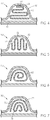
- FIG's 4-7 illustrate other embodiments in which a plurality of fabric insert layers are formed by folding a single piece of fabric. If the fabric is coated with rubber on one or both sides, the folding will result in layers of fabric and rubber useful for reinforcing the belt teeth.
- the rubber layer may be the same or different than the rest of the tooth rubber or the rubber coating the jacket.
- the tooth 40 embodiment of FIG. 4 includes a one-piece fabric insert 42 with a plurality of horizontal layers 44 as in FIG. 2 , but connected by folds 46 in the one piece of fabric.
- the tooth 50 embodiment of FIG. 5 includes a one-piece fabric insert 52 with a plurality of vertical layers 54 as in FIG. 3 , but connected by folds 56 in the one piece of fabric.
- the tooth 60 embodiment of FIG. 6 includes a one-piece fabric insert 62 with a plurality of spiraled layers 44 in the one piece of fabric.
- the tooth 70 embodiment of FIG. 7 includes a one-piece fabric insert 72 with a plurality of U-shaped (or inverted U-shaped) layers 74 as in FIG. 1 , but connected by folds 76 in the one piece of fabric.
- the fabric inserts or insert layers are not limited to the specific number, sizes and shapes illustrated herein.
- the inserts of the first embodiment may be more than two or three in number. With thinner insert fabrics, more layers can be incorporated while maintaining some suitable, thin rubber layers there between.
- the inserts may be spaced apart from each other or from the jacket or tensile member.
- the inserts or one or more of them maybe be adjacent to or in contact with the jacket, another insert, or the tensile member.
- the inserts may be made by treating a base fabric with dips, coatings, adhesives, and/or rubber layers. Rubber layers may be applied by calender in a frictioning or a skimming process.
- the insert may be built up before applying, or layers of inserts may be applied individually in the belt building process to be described further below.
- the inserts may be built up on tooth fabric 13 at the desired spacing, then applied to the belt mold or preformed.
- FIG's 10 and 11 illustrate two possible arrangements having two fabric layers in the land region 21.
- FIG. 10 shows first jacket 13 and second inner jacket layer 13' with three inserts 101, 102, and 103 in the tooth for belt 100.
- FIG. 11 shows first jacket 13 and second inner jacket 13" with inserts 101, 102, and 103, placed in between the two jackets in the teeth.
- one could have more than one fabric layer in the land region 21 if desired, along with or as extensions of one or more inserts in the tooth.
- One or more of said inserts could extend into the land region.
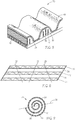
- One way to prepare the horizontal inserts of the second embodiment is to construct a laminate with the desired number of insert layers and rubber layers, and then cut the laminate at an angle repeatedly to make the desired tooth inserts.
- FIG. 8 illustrates this process.
- fabric layers 26, 27, 28 are laminated with rubber layers 24. Cuts 25 result in four trapezoidal inserts with three fabric layers each.
- the outer jacket would still need to be pre-formed and some rubber would still need to flow through the cord to fully fill the tooth. This could give horizontal inserts with no material in the land area. Any width of laminate could be used, and any number of cuts.
- FIG. 9 illustrates this process.
- roll 91 includes rubber layer 24.
- Cutting at 25 results in 2 sets of U-shaped inserts 92, 93, and 94.
- the sheet of stock and fabric layered together could be wound around a suitable-diameter bar and then the sample cut in half and each half used as an insert in the tooth prior to winding cord.
- the outer jacket would still need to be pre-formed and some rubber would still need to flow through the cord to fully fill the tooth. This could give U-shaped inserts with no material in the land area.
- Any elastomer matrix or rubber compound desired may be used in the tooth, back rubber, adhesion gum around the tensile cord, or elsewhere in the belt.
- rubber compounds may be based on nitrile-butadiene elastomers, polychloroprene, natural rubber, butyl elastomers, ethylene-alpha-olefin elastomers, polyurethane, other ethylene-copolymer elastomers, and the like. Rubber compounds may include fillers, short fibers, plasticizers, antidegradants, process aids, curatives and so on as known in the art. Liquefied elastomers such as cast polyurethanes may be used.
- the tensile member may be any known in the art, including for example, cords of fiberglass, carbon fiber, boron, aramid, nylon, polyester, PBO, or hybrids or the like. They may include binders, sizes or adhesive treatments as needed.
- the synchronous belts of the invention may have any desired tooth profile, such as trapezoidal, curvilinear, helical, etc.
- the nominal belt size may be any desired size, although the benefits of reinforcing fabric inserts may be most significant in the larger belt sizes, from standard automotive sizes of 8-mm or 9.525-mm (0.375 inch) pitch up to the largest industrial belt sizes.
- a preform method is preferred.
- the jacket for covering the teeth is first formed to the approximate shape of the surface it is to cover. This may be done on the grooved mold that is to be used to form the entire belt, or on a separate profiled mold or machine developed for that purpose.
- the jacket may include a fabric and various treatments including finishes, adhesives, coatings, rubber layers or thermoplastic layers, as needed. Examples of preform methods of belt manufacturing are described in U.S. Pat. Nos. 3,250,653 , 3,973,894 , 4,235,119 , 6,406,397 , and 9,353,827 .
- the preform method is particularly useful for jackets with limited or no stretch which cannot be shaped by the flow-through method.
- the preform method is advantageous in that it allows the inserts to be placed in the tooth cavities of the preformed jacket before the tensile member and other layers are applied.
- Initially flat inserts may be deformed somewhat during molding and cure processes. Curved inserts may also change shape somewhat during molding under pressure.
- the belt building process may be facilitated by formulating the rubber layers between the insert layers of fabric to be tacky.
- Tacky rubber may be formulated for example by utilizing or incorporating naturally tacky elastomers, specific tackifiers, low-molecular weight elastomer grades, plasticizers, or other known methods. Appropriate use of heat or solvents during building may also facilitate tackiness.
- FIG. 12 shows the control model, that is, a synchronous belt tooth 80 with jacket 13, tensile layer 18 and tooth rubber 24 with no fabric inserts or additional reinforcements. Belt back nodes 19 were constrained in the y-direction. Tooth flank nodes 82 were completely constrained. Tensile layer 18 was displaced in the direction indicated by arrow 84.
- FIG. 13 shows the numerical model for the first embodiment, having two U-shaped inserts 22 and 23 in tooth 90 separated by tooth rubber 24, but generally parallel to the contour of the tooth. Otherwise, the model is identical to the control model of FIG. 12 .
- the U-shaped or contoured inserts were given a very high stiffness value in order to explore the upper limits of the reinforcement effect.
- FIG. 14 shows the numerical model for belt tooth 100 with a plurality of horizontal reinforcing inserts 86. Seven inserts are used in FIG. 14 , again to explore the upper limits of the tooth stiffening effect of the second embodiment.
- FIG. 15 shows the numerical model for belt tooth 110 with a plurality of vertical reinforcing inserts 88. Five inserts are used in FIG. 15 to explore the upper limits of the tooth stiffening effect of the third embodiment.
- the calculated stiffness results were normalized by dividing by the calculated stiffness of the control model.
- the tooth stiffness results are shown TABLE 1. It can be seen that each of the three embodiments results in very significant stiffening of the belt tooth relative to the control.
- the first embodiment may make the tooth almost five times stiffer than the control.
- the second embodiment may more than double the tooth stiffness.
- the third embodiment may make the tooth more than four times stiffer than the control.
- embodiments of the invention may provide significant enhancements to the stiffness of the teeth of a synchronous belt, which may improve the load capacity of the belt.
Landscapes
- Engineering & Computer Science (AREA)
- General Engineering & Computer Science (AREA)
- Mechanical Engineering (AREA)
- Textile Engineering (AREA)
- Laminated Bodies (AREA)
Claims (12)
- Courroie synchrone (10 ; 20 ; 30 ; 40 ; 50 ; 60 ; 70) comprenant :une couche d'élément de tension (18) ayant un élément de tension (12) incorporé dans un corps élastomère (29) ;une surface dentée comprenant une pluralité de dents transversales régulièrement espacées (11) faisant saillie depuis le corps (29) et des méplats (29) entre elles ; etune enveloppe (13) recouvrant la surface dentée ;dans laquelle les dents (11) comprennent une pluralité de couches insérées de tissu (22, 23 ; 26, 27, 28 ; 36, 37, 38 ; 42 ; 52 ; 62 ; 72) qui augmentent la rigidité de la dent, les couches insérées étant séparées les unes des autres par des couches d'une composition élastomère (24) et lesdites couches insérées de tissu étant incorporées dans le caoutchouc de la dent.
- Courroie synchrone (10 ; 20 ; 30) de la revendication 1 dans laquelle la pluralité de couches insérées de tissu (22, 23 ; 26, 27, 28 ; 36, 37, 38) sont des morceaux séparés de tissu.
- Courroie synchrone (10) de la revendication 2 dans laquelle la pluralité de couches insérées de tissu (22, 23) présentent une forme en U qui est généralement parallèle au contour de la dent.
- Courroie synchrone (20) de la revendication 2 dans laquelle ladite pluralité de couches insérées de tissu (26, 27, 28) sont planes et généralement orientées parallèlement à la couche d'élément de tension (18).
- Courroie synchrone (30) de la revendication 2 dans laquelle ladite pluralité de couches insérées de tissu (36, 37, 38) sont planes et généralement orientées perpendiculairement à l'élément de tension (12) ou inclinées au plus autant que la surface de flanc de la dent par rapport à l'élément de tension.
- Courroie synchrone (40 ; 50 ; 60 ; 70) de la revendication 1 dans laquelle la pluralité de couches insérées de tissu (42 ; 52 ; 62 ; 72) constituent un unique morceau de tissu.
- Courroie synchrone (70) de la revendication 6 dans laquelle la pluralité de couches insérées de tissu (72) sont pliées en une forme de U qui est généralement parallèle au contour de la dent.
- Courroie synchrone (40) de la revendication 6 dans laquelle ladite pluralité de couches insérées de tissu (42) sont reliées par des plis (46) dans l'unique morceau de tissu, et sont planes et généralement orientées parallèlement à la couche d'élément de tension (18).
- Courroie synchrone (50) de la revendication 6 dans laquelle ladite pluralité de couches insérées de tissu (52) sont reliées par des plis (56) dans l'unique morceau de tissu, sont planes et généralement orientées perpendiculairement à l'élément de tension (12) ou inclinées au plus autant que la surface de flanc de la dent par rapport à l'élément de tension (12).
- Courroie synchrone (60) de la revendication 6 dans laquelle ladite pluralité de couches insérées de tissu (62) sont formées par enroulement en spirale de l'unique morceau de tissu.
- Courroie synchrone de la revendication 1 ayant des dents (11) et des méplats (21) alternés, et dans laquelle lesdites couches insérées ne s'étendent pas à l'intérieur des méplats (21).
- Courroie synchrone de la revendication 1 ayant des dents et des méplats alternés, et dans laquelle une ou plusieurs desdites couches insérées s'étendent l'intérieur des méplats.
Applications Claiming Priority (2)
| Application Number | Priority Date | Filing Date | Title |
|---|---|---|---|
| US201762490988P | 2017-04-27 | 2017-04-27 | |
| PCT/US2018/029917 WO2018201030A1 (fr) | 2017-04-27 | 2018-04-27 | Courroie synchrone à dents raidies |
Publications (2)
| Publication Number | Publication Date |
|---|---|
| EP3615838A1 EP3615838A1 (fr) | 2020-03-04 |
| EP3615838B1 true EP3615838B1 (fr) | 2021-06-02 |
Family
ID=62148551
Family Applications (1)
| Application Number | Title | Priority Date | Filing Date |
|---|---|---|---|
| EP18724107.0A Active EP3615838B1 (fr) | 2017-04-27 | 2018-04-27 | Courroie synchrone à dents raidies |
Country Status (9)
| Country | Link |
|---|---|
| US (1) | US10989274B2 (fr) |
| EP (1) | EP3615838B1 (fr) |
| JP (1) | JP6878682B2 (fr) |
| KR (1) | KR102389737B1 (fr) |
| CN (1) | CN110573767B (fr) |
| AU (1) | AU2018260779B2 (fr) |
| CA (1) | CA3060194C (fr) |
| MX (1) | MX2019012836A (fr) |
| WO (1) | WO2018201030A1 (fr) |
Families Citing this family (7)
| Publication number | Priority date | Publication date | Assignee | Title |
|---|---|---|---|---|
| JP6641513B2 (ja) * | 2018-04-06 | 2020-02-05 | 三ツ星ベルト株式会社 | はす歯ベルトおよびベルト伝動装置 |
| JP6746818B1 (ja) * | 2019-04-16 | 2020-08-26 | 三ツ星ベルト株式会社 | Vリブドベルトとその製造方法、およびゴム組成物 |
| IT201900025243A1 (it) * | 2019-12-23 | 2021-06-23 | Dayco Europe Srl | Cinghia di trasmissione di potenza e relativo sistema di trasmissione |
| JP7085699B1 (ja) * | 2021-01-25 | 2022-06-16 | 三ツ星ベルト株式会社 | 歯付ベルト |
| CN117980626A (zh) * | 2021-08-18 | 2024-05-03 | 盖茨公司 | 同步带纤维处理剂和带 |
| WO2024163954A1 (fr) * | 2023-02-02 | 2024-08-08 | Gates Corporation | Courroie renforcée multicouche |
| WO2025189193A1 (fr) * | 2024-03-08 | 2025-09-12 | Gates Corporation | Courroies industrielles stratifiées et procédés pour leur fabrication |
Family Cites Families (42)
| Publication number | Priority date | Publication date | Assignee | Title |
|---|---|---|---|---|
| DE1273806B (de) | 1958-03-24 | 1968-07-25 | Goodyear Tire & Rubber | Verfahren und Einrichtung zum Herstellen endloser Riemen |
| US3535946A (en) | 1968-01-05 | 1970-10-27 | Uniroyal Inc | Positive drive belt |
| US3973894A (en) | 1970-11-02 | 1976-08-10 | Continental Gummi-Werke Aktiengesellschaft | Device for the production of toothed belts |
| US3835720A (en) | 1973-08-10 | 1974-09-17 | Dayco Corp | Endless power transmission belt and method of making same |
| IT1054422B (it) * | 1975-12-05 | 1981-11-10 | Pirelli | Cinghia dentata termooleoresistente |
| US4235119A (en) | 1978-11-02 | 1980-11-25 | Dayco Corporation | Toothed belt |
| JPS5578852U (fr) * | 1978-11-27 | 1980-05-30 | ||
| US4514179A (en) | 1983-03-02 | 1985-04-30 | Uniroyal, Inc. | Power transmission belt with fabric cover |
| US4583963A (en) | 1983-06-09 | 1986-04-22 | Dayco Corporation | Belt construction having enhanced tooth strength |
| JPS6062641U (ja) * | 1983-10-07 | 1985-05-01 | 三ツ星ベルト株式会社 | 歯付ベルト |
| US4626232A (en) | 1984-10-09 | 1986-12-02 | Dayco Corporation | Belt construction and method of making the same |
| US4617075A (en) | 1984-10-09 | 1986-10-14 | Dayco Corporation | Method of making a belt |
| DE222637T1 (de) * | 1985-10-29 | 1987-11-05 | Hutchinson S.A., Paris | Treibriemen. |
| FR2589209B1 (fr) * | 1985-10-29 | 1989-06-02 | Hutchinson | Courroie de transmission de puissance perfectionnee |
| FR2597564B2 (fr) | 1986-04-21 | 1989-08-18 | Hutchinson | Courroie de transmission de puissance perfectionnee |
| JPS62136649U (fr) * | 1986-02-20 | 1987-08-28 | ||
| US4775357A (en) | 1987-03-06 | 1988-10-04 | The Goodyear Tire & Rubber Company | Positive drive belt |
| JPS63246532A (ja) | 1987-03-31 | 1988-10-13 | Bando Chem Ind Ltd | 伝動ベルト |
| FR2624238B1 (fr) * | 1987-12-08 | 1990-05-04 | Hutchinson | Perfectionnements aux courroies de transmission de puissance |
| FR2685747B1 (fr) * | 1991-12-26 | 1997-09-26 | Caoutchouc Manuf Plastique | Courroie a denture, resistant a l'huile et a la chaleur par association d'elastomeres. |
| US6406397B1 (en) | 1996-06-20 | 2002-06-18 | Unitta Company | Toothed belt including short fibers distributed therein |
| EP1185470B1 (fr) * | 1998-06-12 | 2004-03-03 | The Gates Corporation | Composites thermoplastiques flexibles haute temperature pour surfaces d'entrainement de courroie sans fin |
| GB2349113B (en) * | 1999-04-21 | 2003-07-02 | Gates Corp | Wear resistant belts and a process for their manufacture |
| US6485386B2 (en) | 2000-05-18 | 2002-11-26 | The Gates Corporation | Transverse reinforced CVT belt |
| IT1320359B1 (it) * | 2000-05-23 | 2003-11-26 | Dayco Europe Srl | Cinghia dentata. |
| EP1546575A1 (fr) * | 2002-07-29 | 2005-06-29 | The Gates Corporation | Courroie |
| EP1735543B1 (fr) * | 2004-02-23 | 2008-04-09 | DAYCO EUROPE S.r.l. | Courroie dentee |
| JP2005264994A (ja) | 2004-03-17 | 2005-09-29 | Tsubakimoto Chain Co | 低騒音歯付ベルト |
| DE102004062760A1 (de) * | 2004-12-21 | 2006-06-22 | Contitech Antriebssysteme Gmbh | Zahnriemen mit Zahnauflage aus Gewebe |
| US8932165B2 (en) * | 2006-03-31 | 2015-01-13 | The Gates Corporation | Toothed power transmission belt |
| US9353827B2 (en) | 2009-10-13 | 2016-05-31 | Gates Unitta Asia Company | Toothed belt |
| AU2012221398B2 (en) * | 2011-02-24 | 2016-04-28 | Gates Corporation | Toothed belt |
| DE102011050483A1 (de) | 2011-05-19 | 2012-11-22 | Contitech Antriebssysteme Gmbh | Antriebsriemen mit einem Verstärkungsband oder einem Verstärkungsgeflecht oder mit zonenweise angeordneten Verstärkungselementen innerhalb des Unterbaus |
| JP5885240B2 (ja) | 2011-11-21 | 2016-03-15 | ゲイツ・ユニッタ・アジア株式会社 | 伝動ベルト |
| ITTO20120080A1 (it) * | 2012-01-31 | 2013-08-01 | Dayco Europe Srl | Uso di una cinghia di trasmissione in olio e relativo sistema di trasmissione |
| CN203570919U (zh) | 2013-11-22 | 2014-04-30 | 宁波丰茂远东橡胶有限公司 | 抗静电汽车多楔带 |
| US9829066B2 (en) * | 2014-04-07 | 2017-11-28 | Gates Corporation | Electrically conductive power transmission belt |
| DE102014012189A1 (de) * | 2014-08-20 | 2016-02-25 | Arntz Beteiligungs Gmbh & Co. Kg | Kraftübertragungsriemen |
| JP6450151B2 (ja) | 2014-11-07 | 2019-01-09 | バンドー化学株式会社 | 動力伝達ベルト |
| JP2015132385A (ja) * | 2015-03-25 | 2015-07-23 | ダイコ ヨーロッパ エス. アール. エル. | 歯付ベルト及びオイル中での歯付ベルトの使用 |
| CN205226231U (zh) | 2015-12-11 | 2016-05-11 | 韩俊伟 | 震动环境专用齿形带 |
| US10220545B2 (en) * | 2016-04-30 | 2019-03-05 | Contitech Antriebssysteme Gmbh | Water based urethane as predip for carbon fiber cord |
-
2018
- 2018-04-27 EP EP18724107.0A patent/EP3615838B1/fr active Active
- 2018-04-27 JP JP2020506138A patent/JP6878682B2/ja active Active
- 2018-04-27 AU AU2018260779A patent/AU2018260779B2/en active Active
- 2018-04-27 KR KR1020197034957A patent/KR102389737B1/ko active Active
- 2018-04-27 CA CA3060194A patent/CA3060194C/fr active Active
- 2018-04-27 CN CN201880027345.2A patent/CN110573767B/zh active Active
- 2018-04-27 US US15/965,392 patent/US10989274B2/en active Active
- 2018-04-27 MX MX2019012836A patent/MX2019012836A/es unknown
- 2018-04-27 WO PCT/US2018/029917 patent/WO2018201030A1/fr not_active Ceased
Non-Patent Citations (1)
| Title |
|---|
| None * |
Also Published As
| Publication number | Publication date |
|---|---|
| CN110573767A (zh) | 2019-12-13 |
| AU2018260779B2 (en) | 2021-05-06 |
| KR20190141744A (ko) | 2019-12-24 |
| AU2018260779A1 (en) | 2019-10-31 |
| EP3615838A1 (fr) | 2020-03-04 |
| JP2020516834A (ja) | 2020-06-11 |
| CN110573767B (zh) | 2021-08-17 |
| US20180313430A1 (en) | 2018-11-01 |
| CA3060194C (fr) | 2021-11-16 |
| CA3060194A1 (fr) | 2018-11-01 |
| US10989274B2 (en) | 2021-04-27 |
| WO2018201030A1 (fr) | 2018-11-01 |
| MX2019012836A (es) | 2019-11-28 |
| JP6878682B2 (ja) | 2021-06-02 |
| KR102389737B1 (ko) | 2022-04-21 |
Similar Documents
| Publication | Publication Date | Title |
|---|---|---|
| EP3615838B1 (fr) | Courroie synchrone à dents raidies | |
| US9091324B2 (en) | Power transmission belt and method of making same | |
| EP3065940B1 (fr) | Courroie comprenant une corde à deux composants intégrés et procédé de fabrication de courroies de transmission | |
| KR910008230B1 (ko) | 동력 전달 벨트 | |
| EP2425151B1 (fr) | Courroie en v dentée double pour entraînement à vitesse variable | |
| JPH0243060B2 (fr) | ||
| EP3734111B1 (fr) | Courroie crantée à double face | |
| KR20090099582A (ko) | 프롱형 슬리브식 가요성 샤프트 커플링 | |
| US20190177889A1 (en) | Method of weaving tubular fabric, the fabric, and a belt using the fabric | |
| GB2076740A (en) | Laminated belt | |
| CN101407108B (zh) | 管状体的制造方法及该管状体 | |
| CZ20023817A3 (cs) | Příčně vyztužený řemen pro kontinuálně měnitelné převody a způsob jeho výroby | |
| EP3263947B1 (fr) | Procédé de fabrication de tissu de renfort pour une courroie de transmission | |
| DE3628598C2 (fr) | ||
| JP2010210088A (ja) | 歯付きベルト | |
| EP4574423A1 (fr) | Produit en caoutchouc et son procédé de production | |
| EP4004400B1 (fr) | Courroie en v à ligne de câbles centrale | |
| JP2001293792A (ja) | プロファイル付き歯付ベルトの製造方法 | |
| JP2012250349A (ja) | 歯付ベルトの製造方法 |
Legal Events
| Date | Code | Title | Description |
|---|---|---|---|
| STAA | Information on the status of an ep patent application or granted ep patent |
Free format text: STATUS: UNKNOWN |
|
| STAA | Information on the status of an ep patent application or granted ep patent |
Free format text: STATUS: THE INTERNATIONAL PUBLICATION HAS BEEN MADE |
|
| PUAI | Public reference made under article 153(3) epc to a published international application that has entered the european phase |
Free format text: ORIGINAL CODE: 0009012 |
|
| STAA | Information on the status of an ep patent application or granted ep patent |
Free format text: STATUS: REQUEST FOR EXAMINATION WAS MADE |
|
| 17P | Request for examination filed |
Effective date: 20191016 |
|
| AK | Designated contracting states |
Kind code of ref document: A1 Designated state(s): AL AT BE BG CH CY CZ DE DK EE ES FI FR GB GR HR HU IE IS IT LI LT LU LV MC MK MT NL NO PL PT RO RS SE SI SK SM TR |
|
| AX | Request for extension of the european patent |
Extension state: BA ME |
|
| DAV | Request for validation of the european patent (deleted) | ||
| DAX | Request for extension of the european patent (deleted) | ||
| GRAP | Despatch of communication of intention to grant a patent |
Free format text: ORIGINAL CODE: EPIDOSNIGR1 |
|
| STAA | Information on the status of an ep patent application or granted ep patent |
Free format text: STATUS: GRANT OF PATENT IS INTENDED |
|
| INTG | Intention to grant announced |
Effective date: 20201204 |
|
| GRAS | Grant fee paid |
Free format text: ORIGINAL CODE: EPIDOSNIGR3 |
|
| GRAA | (expected) grant |
Free format text: ORIGINAL CODE: 0009210 |
|
| STAA | Information on the status of an ep patent application or granted ep patent |
Free format text: STATUS: THE PATENT HAS BEEN GRANTED |
|
| REG | Reference to a national code |
Ref country code: CH Ref legal event code: EP |
|
| AK | Designated contracting states |
Kind code of ref document: B1 Designated state(s): AL AT BE BG CH CY CZ DE DK EE ES FI FR GB GR HR HU IE IS IT LI LT LU LV MC MK MT NL NO PL PT RO RS SE SI SK SM TR |
|
| REG | Reference to a national code |
Ref country code: GB Ref legal event code: FG4D |
|
| REG | Reference to a national code |
Ref country code: AT Ref legal event code: REF Ref document number: 1398742 Country of ref document: AT Kind code of ref document: T Effective date: 20210615 |
|
| REG | Reference to a national code |
Ref country code: IE Ref legal event code: FG4D |
|
| REG | Reference to a national code |
Ref country code: DE Ref legal event code: R096 Ref document number: 602018018069 Country of ref document: DE |
|
| REG | Reference to a national code |
Ref country code: LT Ref legal event code: MG9D |
|
| PG25 | Lapsed in a contracting state [announced via postgrant information from national office to epo] |
Ref country code: BG Free format text: LAPSE BECAUSE OF FAILURE TO SUBMIT A TRANSLATION OF THE DESCRIPTION OR TO PAY THE FEE WITHIN THE PRESCRIBED TIME-LIMIT Effective date: 20210902 Ref country code: FI Free format text: LAPSE BECAUSE OF FAILURE TO SUBMIT A TRANSLATION OF THE DESCRIPTION OR TO PAY THE FEE WITHIN THE PRESCRIBED TIME-LIMIT Effective date: 20210602 Ref country code: LT Free format text: LAPSE BECAUSE OF FAILURE TO SUBMIT A TRANSLATION OF THE DESCRIPTION OR TO PAY THE FEE WITHIN THE PRESCRIBED TIME-LIMIT Effective date: 20210602 Ref country code: HR Free format text: LAPSE BECAUSE OF FAILURE TO SUBMIT A TRANSLATION OF THE DESCRIPTION OR TO PAY THE FEE WITHIN THE PRESCRIBED TIME-LIMIT Effective date: 20210602 |
|
| REG | Reference to a national code |
Ref country code: NL Ref legal event code: MP Effective date: 20210602 |
|
| REG | Reference to a national code |
Ref country code: AT Ref legal event code: MK05 Ref document number: 1398742 Country of ref document: AT Kind code of ref document: T Effective date: 20210602 |
|
| PG25 | Lapsed in a contracting state [announced via postgrant information from national office to epo] |
Ref country code: LV Free format text: LAPSE BECAUSE OF FAILURE TO SUBMIT A TRANSLATION OF THE DESCRIPTION OR TO PAY THE FEE WITHIN THE PRESCRIBED TIME-LIMIT Effective date: 20210602 Ref country code: NO Free format text: LAPSE BECAUSE OF FAILURE TO SUBMIT A TRANSLATION OF THE DESCRIPTION OR TO PAY THE FEE WITHIN THE PRESCRIBED TIME-LIMIT Effective date: 20210902 Ref country code: PL Free format text: LAPSE BECAUSE OF FAILURE TO SUBMIT A TRANSLATION OF THE DESCRIPTION OR TO PAY THE FEE WITHIN THE PRESCRIBED TIME-LIMIT Effective date: 20210602 Ref country code: RS Free format text: LAPSE BECAUSE OF FAILURE TO SUBMIT A TRANSLATION OF THE DESCRIPTION OR TO PAY THE FEE WITHIN THE PRESCRIBED TIME-LIMIT Effective date: 20210602 Ref country code: SE Free format text: LAPSE BECAUSE OF FAILURE TO SUBMIT A TRANSLATION OF THE DESCRIPTION OR TO PAY THE FEE WITHIN THE PRESCRIBED TIME-LIMIT Effective date: 20210602 Ref country code: GR Free format text: LAPSE BECAUSE OF FAILURE TO SUBMIT A TRANSLATION OF THE DESCRIPTION OR TO PAY THE FEE WITHIN THE PRESCRIBED TIME-LIMIT Effective date: 20210903 |
|
| PG25 | Lapsed in a contracting state [announced via postgrant information from national office to epo] |
Ref country code: ES Free format text: LAPSE BECAUSE OF FAILURE TO SUBMIT A TRANSLATION OF THE DESCRIPTION OR TO PAY THE FEE WITHIN THE PRESCRIBED TIME-LIMIT Effective date: 20210602 Ref country code: EE Free format text: LAPSE BECAUSE OF FAILURE TO SUBMIT A TRANSLATION OF THE DESCRIPTION OR TO PAY THE FEE WITHIN THE PRESCRIBED TIME-LIMIT Effective date: 20210602 Ref country code: SK Free format text: LAPSE BECAUSE OF FAILURE TO SUBMIT A TRANSLATION OF THE DESCRIPTION OR TO PAY THE FEE WITHIN THE PRESCRIBED TIME-LIMIT Effective date: 20210602 Ref country code: CZ Free format text: LAPSE BECAUSE OF FAILURE TO SUBMIT A TRANSLATION OF THE DESCRIPTION OR TO PAY THE FEE WITHIN THE PRESCRIBED TIME-LIMIT Effective date: 20210602 Ref country code: AT Free format text: LAPSE BECAUSE OF FAILURE TO SUBMIT A TRANSLATION OF THE DESCRIPTION OR TO PAY THE FEE WITHIN THE PRESCRIBED TIME-LIMIT Effective date: 20210602 Ref country code: NL Free format text: LAPSE BECAUSE OF FAILURE TO SUBMIT A TRANSLATION OF THE DESCRIPTION OR TO PAY THE FEE WITHIN THE PRESCRIBED TIME-LIMIT Effective date: 20210602 Ref country code: PT Free format text: LAPSE BECAUSE OF FAILURE TO SUBMIT A TRANSLATION OF THE DESCRIPTION OR TO PAY THE FEE WITHIN THE PRESCRIBED TIME-LIMIT Effective date: 20211004 Ref country code: RO Free format text: LAPSE BECAUSE OF FAILURE TO SUBMIT A TRANSLATION OF THE DESCRIPTION OR TO PAY THE FEE WITHIN THE PRESCRIBED TIME-LIMIT Effective date: 20210602 Ref country code: SM Free format text: LAPSE BECAUSE OF FAILURE TO SUBMIT A TRANSLATION OF THE DESCRIPTION OR TO PAY THE FEE WITHIN THE PRESCRIBED TIME-LIMIT Effective date: 20210602 |
|
| REG | Reference to a national code |
Ref country code: DE Ref legal event code: R097 Ref document number: 602018018069 Country of ref document: DE |
|
| PLBE | No opposition filed within time limit |
Free format text: ORIGINAL CODE: 0009261 |
|
| STAA | Information on the status of an ep patent application or granted ep patent |
Free format text: STATUS: NO OPPOSITION FILED WITHIN TIME LIMIT |
|
| PG25 | Lapsed in a contracting state [announced via postgrant information from national office to epo] |
Ref country code: DK Free format text: LAPSE BECAUSE OF FAILURE TO SUBMIT A TRANSLATION OF THE DESCRIPTION OR TO PAY THE FEE WITHIN THE PRESCRIBED TIME-LIMIT Effective date: 20210602 |
|
| 26N | No opposition filed |
Effective date: 20220303 |
|
| PG25 | Lapsed in a contracting state [announced via postgrant information from national office to epo] |
Ref country code: AL Free format text: LAPSE BECAUSE OF FAILURE TO SUBMIT A TRANSLATION OF THE DESCRIPTION OR TO PAY THE FEE WITHIN THE PRESCRIBED TIME-LIMIT Effective date: 20210602 |
|
| PG25 | Lapsed in a contracting state [announced via postgrant information from national office to epo] |
Ref country code: IT Free format text: LAPSE BECAUSE OF FAILURE TO SUBMIT A TRANSLATION OF THE DESCRIPTION OR TO PAY THE FEE WITHIN THE PRESCRIBED TIME-LIMIT Effective date: 20210602 |
|
| REG | Reference to a national code |
Ref country code: CH Ref legal event code: PL |
|
| REG | Reference to a national code |
Ref country code: BE Ref legal event code: MM Effective date: 20220430 |
|
| PG25 | Lapsed in a contracting state [announced via postgrant information from national office to epo] |
Ref country code: MC Free format text: LAPSE BECAUSE OF FAILURE TO SUBMIT A TRANSLATION OF THE DESCRIPTION OR TO PAY THE FEE WITHIN THE PRESCRIBED TIME-LIMIT Effective date: 20210602 Ref country code: LU Free format text: LAPSE BECAUSE OF NON-PAYMENT OF DUE FEES Effective date: 20220427 Ref country code: LI Free format text: LAPSE BECAUSE OF NON-PAYMENT OF DUE FEES Effective date: 20220430 Ref country code: CH Free format text: LAPSE BECAUSE OF NON-PAYMENT OF DUE FEES Effective date: 20220430 |
|
| PG25 | Lapsed in a contracting state [announced via postgrant information from national office to epo] |
Ref country code: BE Free format text: LAPSE BECAUSE OF NON-PAYMENT OF DUE FEES Effective date: 20220430 |
|
| PG25 | Lapsed in a contracting state [announced via postgrant information from national office to epo] |
Ref country code: IE Free format text: LAPSE BECAUSE OF NON-PAYMENT OF DUE FEES Effective date: 20220427 |
|
| PG25 | Lapsed in a contracting state [announced via postgrant information from national office to epo] |
Ref country code: MK Free format text: LAPSE BECAUSE OF FAILURE TO SUBMIT A TRANSLATION OF THE DESCRIPTION OR TO PAY THE FEE WITHIN THE PRESCRIBED TIME-LIMIT Effective date: 20210602 Ref country code: CY Free format text: LAPSE BECAUSE OF FAILURE TO SUBMIT A TRANSLATION OF THE DESCRIPTION OR TO PAY THE FEE WITHIN THE PRESCRIBED TIME-LIMIT Effective date: 20210602 |
|
| PG25 | Lapsed in a contracting state [announced via postgrant information from national office to epo] |
Ref country code: HU Free format text: LAPSE BECAUSE OF FAILURE TO SUBMIT A TRANSLATION OF THE DESCRIPTION OR TO PAY THE FEE WITHIN THE PRESCRIBED TIME-LIMIT; INVALID AB INITIO Effective date: 20180427 |
|
| PG25 | Lapsed in a contracting state [announced via postgrant information from national office to epo] |
Ref country code: TR Free format text: LAPSE BECAUSE OF FAILURE TO SUBMIT A TRANSLATION OF THE DESCRIPTION OR TO PAY THE FEE WITHIN THE PRESCRIBED TIME-LIMIT Effective date: 20210602 |
|
| PG25 | Lapsed in a contracting state [announced via postgrant information from national office to epo] |
Ref country code: MT Free format text: LAPSE BECAUSE OF FAILURE TO SUBMIT A TRANSLATION OF THE DESCRIPTION OR TO PAY THE FEE WITHIN THE PRESCRIBED TIME-LIMIT Effective date: 20210602 |
|
| PGFP | Annual fee paid to national office [announced via postgrant information from national office to epo] |
Ref country code: FR Payment date: 20250319 Year of fee payment: 8 |
|
| PGFP | Annual fee paid to national office [announced via postgrant information from national office to epo] |
Ref country code: GB Payment date: 20250319 Year of fee payment: 8 |
|
| PGFP | Annual fee paid to national office [announced via postgrant information from national office to epo] |
Ref country code: DE Payment date: 20250319 Year of fee payment: 8 |