EP4574423A1 - Produit en caoutchouc et son procédé de production - Google Patents
Produit en caoutchouc et son procédé de production Download PDFInfo
- Publication number
- EP4574423A1 EP4574423A1 EP23854684.0A EP23854684A EP4574423A1 EP 4574423 A1 EP4574423 A1 EP 4574423A1 EP 23854684 A EP23854684 A EP 23854684A EP 4574423 A1 EP4574423 A1 EP 4574423A1
- Authority
- EP
- European Patent Office
- Prior art keywords
- cord
- cylindrical portion
- less
- fiber cords
- reinforcing layers
- Prior art date
- Legal status (The legal status is an assumption and is not a legal conclusion. Google has not performed a legal analysis and makes no representation as to the accuracy of the status listed.)
- Pending
Links
Images




Classifications
-
- B—PERFORMING OPERATIONS; TRANSPORTING
- B32—LAYERED PRODUCTS
- B32B—LAYERED PRODUCTS, i.e. PRODUCTS BUILT-UP OF STRATA OF FLAT OR NON-FLAT, e.g. CELLULAR OR HONEYCOMB, FORM
- B32B1/00—Layered products having a non-planar shape
- B32B1/08—Tubular products
-
- B—PERFORMING OPERATIONS; TRANSPORTING
- B29—WORKING OF PLASTICS; WORKING OF SUBSTANCES IN A PLASTIC STATE IN GENERAL
- B29C—SHAPING OR JOINING OF PLASTICS; SHAPING OF MATERIAL IN A PLASTIC STATE, NOT OTHERWISE PROVIDED FOR; AFTER-TREATMENT OF THE SHAPED PRODUCTS, e.g. REPAIRING
- B29C35/00—Heating, cooling or curing, e.g. crosslinking or vulcanising; Apparatus therefor
- B29C35/02—Heating or curing, e.g. crosslinking or vulcanizing during moulding, e.g. in a mould
-
- B—PERFORMING OPERATIONS; TRANSPORTING
- B29—WORKING OF PLASTICS; WORKING OF SUBSTANCES IN A PLASTIC STATE IN GENERAL
- B29C—SHAPING OR JOINING OF PLASTICS; SHAPING OF MATERIAL IN A PLASTIC STATE, NOT OTHERWISE PROVIDED FOR; AFTER-TREATMENT OF THE SHAPED PRODUCTS, e.g. REPAIRING
- B29C70/00—Shaping composites, i.e. plastics material comprising reinforcements, fillers or preformed parts, e.g. inserts
- B29C70/04—Shaping composites, i.e. plastics material comprising reinforcements, fillers or preformed parts, e.g. inserts comprising reinforcements only, e.g. self-reinforcing plastics
- B29C70/06—Fibrous reinforcements only
- B29C70/10—Fibrous reinforcements only characterised by the structure of fibrous reinforcements, e.g. hollow fibres
- B29C70/16—Fibrous reinforcements only characterised by the structure of fibrous reinforcements, e.g. hollow fibres using fibres of substantial or continuous length
- B29C70/22—Fibrous reinforcements only characterised by the structure of fibrous reinforcements, e.g. hollow fibres using fibres of substantial or continuous length oriented in at least two directions forming a two-dimensional [2D] structure
-
- B—PERFORMING OPERATIONS; TRANSPORTING
- B29—WORKING OF PLASTICS; WORKING OF SUBSTANCES IN A PLASTIC STATE IN GENERAL
- B29C—SHAPING OR JOINING OF PLASTICS; SHAPING OF MATERIAL IN A PLASTIC STATE, NOT OTHERWISE PROVIDED FOR; AFTER-TREATMENT OF THE SHAPED PRODUCTS, e.g. REPAIRING
- B29C70/00—Shaping composites, i.e. plastics material comprising reinforcements, fillers or preformed parts, e.g. inserts
- B29C70/04—Shaping composites, i.e. plastics material comprising reinforcements, fillers or preformed parts, e.g. inserts comprising reinforcements only, e.g. self-reinforcing plastics
- B29C70/28—Shaping operations therefor
- B29C70/30—Shaping by lay-up, i.e. applying fibres, tape or broadsheet on a mould, former or core; Shaping by spray-up, i.e. spraying of fibres on a mould, former or core
-
- B—PERFORMING OPERATIONS; TRANSPORTING
- B32—LAYERED PRODUCTS
- B32B—LAYERED PRODUCTS, i.e. PRODUCTS BUILT-UP OF STRATA OF FLAT OR NON-FLAT, e.g. CELLULAR OR HONEYCOMB, FORM
- B32B25/00—Layered products comprising a layer of natural or synthetic rubber
- B32B25/10—Layered products comprising a layer of natural or synthetic rubber next to a fibrous or filamentary layer
-
- B—PERFORMING OPERATIONS; TRANSPORTING
- B32—LAYERED PRODUCTS
- B32B—LAYERED PRODUCTS, i.e. PRODUCTS BUILT-UP OF STRATA OF FLAT OR NON-FLAT, e.g. CELLULAR OR HONEYCOMB, FORM
- B32B5/00—Layered products characterised by the non- homogeneity or physical structure, i.e. comprising a fibrous, filamentary, particulate or foam layer; Layered products characterised by having a layer differing constitutionally or physically in different parts
- B32B5/02—Layered products characterised by the non- homogeneity or physical structure, i.e. comprising a fibrous, filamentary, particulate or foam layer; Layered products characterised by having a layer differing constitutionally or physically in different parts characterised by structural features of a fibrous or filamentary layer
- B32B5/024—Woven fabric
-
- B—PERFORMING OPERATIONS; TRANSPORTING
- B32—LAYERED PRODUCTS
- B32B—LAYERED PRODUCTS, i.e. PRODUCTS BUILT-UP OF STRATA OF FLAT OR NON-FLAT, e.g. CELLULAR OR HONEYCOMB, FORM
- B32B5/00—Layered products characterised by the non- homogeneity or physical structure, i.e. comprising a fibrous, filamentary, particulate or foam layer; Layered products characterised by having a layer differing constitutionally or physically in different parts
- B32B5/02—Layered products characterised by the non- homogeneity or physical structure, i.e. comprising a fibrous, filamentary, particulate or foam layer; Layered products characterised by having a layer differing constitutionally or physically in different parts characterised by structural features of a fibrous or filamentary layer
- B32B5/12—Layered products characterised by the non- homogeneity or physical structure, i.e. comprising a fibrous, filamentary, particulate or foam layer; Layered products characterised by having a layer differing constitutionally or physically in different parts characterised by structural features of a fibrous or filamentary layer characterised by the relative arrangement of fibres or filaments of different layers, e.g. the fibres or filaments being parallel or perpendicular to each other
-
- F—MECHANICAL ENGINEERING; LIGHTING; HEATING; WEAPONS; BLASTING
- F16—ENGINEERING ELEMENTS AND UNITS; GENERAL MEASURES FOR PRODUCING AND MAINTAINING EFFECTIVE FUNCTIONING OF MACHINES OR INSTALLATIONS; THERMAL INSULATION IN GENERAL
- F16L—PIPES; JOINTS OR FITTINGS FOR PIPES; SUPPORTS FOR PIPES, CABLES OR PROTECTIVE TUBING; MEANS FOR THERMAL INSULATION IN GENERAL
- F16L11/00—Hoses, i.e. flexible pipes
- F16L11/04—Hoses, i.e. flexible pipes made of rubber or flexible plastics
- F16L11/08—Hoses, i.e. flexible pipes made of rubber or flexible plastics with reinforcements embedded in the wall
-
- F—MECHANICAL ENGINEERING; LIGHTING; HEATING; WEAPONS; BLASTING
- F16—ENGINEERING ELEMENTS AND UNITS; GENERAL MEASURES FOR PRODUCING AND MAINTAINING EFFECTIVE FUNCTIONING OF MACHINES OR INSTALLATIONS; THERMAL INSULATION IN GENERAL
- F16L—PIPES; JOINTS OR FITTINGS FOR PIPES; SUPPORTS FOR PIPES, CABLES OR PROTECTIVE TUBING; MEANS FOR THERMAL INSULATION IN GENERAL
- F16L11/00—Hoses, i.e. flexible pipes
- F16L11/04—Hoses, i.e. flexible pipes made of rubber or flexible plastics
- F16L11/08—Hoses, i.e. flexible pipes made of rubber or flexible plastics with reinforcements embedded in the wall
- F16L11/085—Hoses, i.e. flexible pipes made of rubber or flexible plastics with reinforcements embedded in the wall comprising one or more braided layers
- F16L11/087—Hoses, i.e. flexible pipes made of rubber or flexible plastics with reinforcements embedded in the wall comprising one or more braided layers three or more layers
-
- B—PERFORMING OPERATIONS; TRANSPORTING
- B29—WORKING OF PLASTICS; WORKING OF SUBSTANCES IN A PLASTIC STATE IN GENERAL
- B29K—INDEXING SCHEME ASSOCIATED WITH SUBCLASSES B29B, B29C OR B29D, RELATING TO MOULDING MATERIALS OR TO MATERIALS FOR MOULDS, REINFORCEMENTS, FILLERS OR PREFORMED PARTS, e.g. INSERTS
- B29K2007/00—Use of natural rubber as moulding material
-
- B—PERFORMING OPERATIONS; TRANSPORTING
- B29—WORKING OF PLASTICS; WORKING OF SUBSTANCES IN A PLASTIC STATE IN GENERAL
- B29K—INDEXING SCHEME ASSOCIATED WITH SUBCLASSES B29B, B29C OR B29D, RELATING TO MOULDING MATERIALS OR TO MATERIALS FOR MOULDS, REINFORCEMENTS, FILLERS OR PREFORMED PARTS, e.g. INSERTS
- B29K2009/00—Use of rubber derived from conjugated dienes, as moulding material
- B29K2009/06—SB polymers, i.e. butadiene-styrene polymers
-
- B—PERFORMING OPERATIONS; TRANSPORTING
- B29—WORKING OF PLASTICS; WORKING OF SUBSTANCES IN A PLASTIC STATE IN GENERAL
- B29K—INDEXING SCHEME ASSOCIATED WITH SUBCLASSES B29B, B29C OR B29D, RELATING TO MOULDING MATERIALS OR TO MATERIALS FOR MOULDS, REINFORCEMENTS, FILLERS OR PREFORMED PARTS, e.g. INSERTS
- B29K2267/00—Use of polyesters or derivatives thereof as reinforcement
-
- B—PERFORMING OPERATIONS; TRANSPORTING
- B32—LAYERED PRODUCTS
- B32B—LAYERED PRODUCTS, i.e. PRODUCTS BUILT-UP OF STRATA OF FLAT OR NON-FLAT, e.g. CELLULAR OR HONEYCOMB, FORM
- B32B2255/00—Coating on the layer surface
- B32B2255/02—Coating on the layer surface on fibrous or filamentary layer
-
- B—PERFORMING OPERATIONS; TRANSPORTING
- B32—LAYERED PRODUCTS
- B32B—LAYERED PRODUCTS, i.e. PRODUCTS BUILT-UP OF STRATA OF FLAT OR NON-FLAT, e.g. CELLULAR OR HONEYCOMB, FORM
- B32B2255/00—Coating on the layer surface
- B32B2255/26—Polymeric coating
-
- B—PERFORMING OPERATIONS; TRANSPORTING
- B32—LAYERED PRODUCTS
- B32B—LAYERED PRODUCTS, i.e. PRODUCTS BUILT-UP OF STRATA OF FLAT OR NON-FLAT, e.g. CELLULAR OR HONEYCOMB, FORM
- B32B2260/00—Layered product comprising an impregnated, embedded, or bonded layer wherein the layer comprises an impregnation, embedding, or binder material
- B32B2260/02—Composition of the impregnated, bonded or embedded layer
- B32B2260/021—Fibrous or filamentary layer
-
- B—PERFORMING OPERATIONS; TRANSPORTING
- B32—LAYERED PRODUCTS
- B32B—LAYERED PRODUCTS, i.e. PRODUCTS BUILT-UP OF STRATA OF FLAT OR NON-FLAT, e.g. CELLULAR OR HONEYCOMB, FORM
- B32B2260/00—Layered product comprising an impregnated, embedded, or bonded layer wherein the layer comprises an impregnation, embedding, or binder material
- B32B2260/04—Impregnation, embedding, or binder material
- B32B2260/048—Natural or synthetic rubber
-
- B—PERFORMING OPERATIONS; TRANSPORTING
- B32—LAYERED PRODUCTS
- B32B—LAYERED PRODUCTS, i.e. PRODUCTS BUILT-UP OF STRATA OF FLAT OR NON-FLAT, e.g. CELLULAR OR HONEYCOMB, FORM
- B32B2262/00—Composition or structural features of fibres which form a fibrous or filamentary layer or are present as additives
- B32B2262/02—Synthetic macromolecular fibres
- B32B2262/0276—Polyester fibres
-
- B—PERFORMING OPERATIONS; TRANSPORTING
- B32—LAYERED PRODUCTS
- B32B—LAYERED PRODUCTS, i.e. PRODUCTS BUILT-UP OF STRATA OF FLAT OR NON-FLAT, e.g. CELLULAR OR HONEYCOMB, FORM
- B32B2307/00—Properties of the layers or laminate
- B32B2307/50—Properties of the layers or laminate having particular mechanical properties
- B32B2307/54—Yield strength; Tensile strength
-
- B—PERFORMING OPERATIONS; TRANSPORTING
- B32—LAYERED PRODUCTS
- B32B—LAYERED PRODUCTS, i.e. PRODUCTS BUILT-UP OF STRATA OF FLAT OR NON-FLAT, e.g. CELLULAR OR HONEYCOMB, FORM
- B32B2307/00—Properties of the layers or laminate
- B32B2307/70—Other properties
- B32B2307/718—Weight, e.g. weight per square meter
-
- B—PERFORMING OPERATIONS; TRANSPORTING
- B32—LAYERED PRODUCTS
- B32B—LAYERED PRODUCTS, i.e. PRODUCTS BUILT-UP OF STRATA OF FLAT OR NON-FLAT, e.g. CELLULAR OR HONEYCOMB, FORM
- B32B2307/00—Properties of the layers or laminate
- B32B2307/70—Other properties
- B32B2307/72—Density
-
- B—PERFORMING OPERATIONS; TRANSPORTING
- B32—LAYERED PRODUCTS
- B32B—LAYERED PRODUCTS, i.e. PRODUCTS BUILT-UP OF STRATA OF FLAT OR NON-FLAT, e.g. CELLULAR OR HONEYCOMB, FORM
- B32B2307/00—Properties of the layers or laminate
- B32B2307/70—Other properties
- B32B2307/732—Dimensional properties
- B32B2307/737—Dimensions, e.g. volume or area
- B32B2307/7375—Linear, e.g. length, distance or width
- B32B2307/7376—Thickness
-
- B—PERFORMING OPERATIONS; TRANSPORTING
- B32—LAYERED PRODUCTS
- B32B—LAYERED PRODUCTS, i.e. PRODUCTS BUILT-UP OF STRATA OF FLAT OR NON-FLAT, e.g. CELLULAR OR HONEYCOMB, FORM
- B32B2319/00—Synthetic rubber
-
- B—PERFORMING OPERATIONS; TRANSPORTING
- B32—LAYERED PRODUCTS
- B32B—LAYERED PRODUCTS, i.e. PRODUCTS BUILT-UP OF STRATA OF FLAT OR NON-FLAT, e.g. CELLULAR OR HONEYCOMB, FORM
- B32B2597/00—Tubular articles, e.g. hoses, pipes
-
- B—PERFORMING OPERATIONS; TRANSPORTING
- B32—LAYERED PRODUCTS
- B32B—LAYERED PRODUCTS, i.e. PRODUCTS BUILT-UP OF STRATA OF FLAT OR NON-FLAT, e.g. CELLULAR OR HONEYCOMB, FORM
- B32B2605/00—Vehicles
- B32B2605/12—Ships
-
- Y—GENERAL TAGGING OF NEW TECHNOLOGICAL DEVELOPMENTS; GENERAL TAGGING OF CROSS-SECTIONAL TECHNOLOGIES SPANNING OVER SEVERAL SECTIONS OF THE IPC; TECHNICAL SUBJECTS COVERED BY FORMER USPC CROSS-REFERENCE ART COLLECTIONS [XRACs] AND DIGESTS
- Y02—TECHNOLOGIES OR APPLICATIONS FOR MITIGATION OR ADAPTATION AGAINST CLIMATE CHANGE
- Y02A—TECHNOLOGIES FOR ADAPTATION TO CLIMATE CHANGE
- Y02A30/00—Adapting or protecting infrastructure or their operation
- Y02A30/30—Adapting or protecting infrastructure or their operation in transportation, e.g. on roads, waterways or railways
Definitions
- the present invention relates to a rubber product and a method of producing the same and particularly relates to a rubber product including a cylindrical portion in which a plurality of reinforcing layers are coaxially layered and embedded between an inner layer and an outer layer and a method of producing the same.
- a reinforcing layer is embedded in a cylindrical portion of a rubber product such as a pneumatic fender or a marine hose.
- the reinforcing layer is embedded to resist internal pressure acting on the rubber product.
- a reinforcing layer composed of a cord fabric having a large number of aligned fiber cords and coating rubber layers covering both surfaces of the cord fabric is used (see Patent Document 1).
- a plurality of reinforcing layers are layered and embedded between an inner layer and an outer layer of a cylindrical portion, and fiber cords of the reinforcing layers layered adjacently extend in intersecting directions (so-called bias structure).
- the coating rubber layer interposed between the cord fabrics layered adjacently is set at an appropriate layer thickness for ensuring sufficient joining strength.
- the time required for a layering operation of the reinforcing layers becomes longer, which is disadvantageous in improving productivity of the rubber product.
- the increase in number of the layered reinforcing layers results in an increase in weight, which is a cause of a deterioration in molding processability.
- An excessively large layer thickness of the coating rubber layer results in deteriorated molding processability.
- an excessively small layer thickness of the coating rubber layer causes insufficient joining strength between the reinforcing layers and joining strength between the reinforcing layer and an adjacent member, which is disadvantageous in ensuring sufficient pressure resistance. Therefore, there is room for improvement in improving productivity by reducing the number of the layered reinforcing layers embedded in the cylindrical portion while ensuring sufficient pressure resistance against the internal pressure, and in suppressing a deterioration in molding processability.
- Patent Document 1 JP 10-157016 A
- a main object of the present invention is to provide a rubber product that can improve productivity by reducing the number of layered reinforcing layers embedded in a cylindrical portion while ensuring sufficient pressure resistance against internal pressure, and that can suppress a deterioration in molding processability, and a method of producing the rubber product.
- Each of the cord fabrics having specifications: a tensile strength of 4320 N/cm or more in an extension direction in which the fiber cords extend and a weight of 950 g/m 2 or less may be used, each of the cord fabrics may have a bending hardness of 30 g/cm or less after the predetermined adhesion treatment, and each of the coating rubber layers may have a layer thickness of 0.2 mm or more and 1 mm or less in a neutral state where the cylindrical portion is not expanded.
- a method of producing a rubber product according to an embodiment of the present invention is a method of producing a rubber product including molding a molded body having a cylindrical shape in which a plurality of reinforcing layers are coaxially layered between an inner layer and an outer layer, composing each of the reinforcing layers of cord fabrics that include a large number of fiber cords aligned and is subjected to a predetermined adhesion treatment and coating rubber layers covering both surfaces of the cord fabric, forming a bias structure in which the fiber cords of each of the reinforcing layers extend in an intersecting direction, and producing, by vulcanizing the molded body, a rubber product including a cylindrical portion in which the plurality of reinforcing layers are coaxially layered and embedded between the inner layer and the outer layer.
- the method may include using each of the cord fabrics having specifications: a tensile strength of 4320 N/cm or more in an extension direction of the fiber cords and a weight of 950 g/m 2 or less may be used, making each of the cord fabrics have a bending hardness of 30 g/cm or less after the predetermined adhesion treatment, and making each of the coating rubber layers have a layer thickness of 0.2 mm or more and 1 mm or less.
- the cord fabric having a specification: a tensile strength of 4320 N/cm or more in the direction in which the fiber cords extend is used as each of the cord fabrics, sufficient pressure resistance against internal pressure acting on the rubber product can be easily ensured even when the number of the layered reinforcing layers embedded in the cylindrical portion is reduced. In turn, it is advantageous in improvement in productivity of the rubber product.
- Each of the cord fabrics has a weight of 950 g/m 2 or less and a bending hardness of 30 g/cm or less after the predetermined adhesion treatment, which is advantageous in suppressing a deterioration in molding processability when producing the rubber product.
- each of the coating rubber layers has a layer thickness of 0.2 mm or more and 1 mm or less, it becomes easy to ensure sufficient joining strength while suppressing an increase in weight, which is more advantageous in ensuring pressure resistance while suppressing a deterioration in molding processability.
- a rubber product according to an embodiment of the present invention and a method of producing the same will be described below with reference to the drawings by taking a case where the rubber product is a pneumatic fender as an example.
- a pneumatic fender 1 (hereinafter referred to as fender 1) according to an embodiment of a rubber product illustrated in FIGS. 1 to 3 includes: a body 2 including hemispherical portions 3b connected to both ends of a cylindrical portion 3a; and a mouthpiece portion 11 provided on the body 2.
- the mouthpiece portion 11 is provided on one of the hemispherical portions 3b, but may be provided on the hemispherical portions 3b on both sides.
- a one dot chain line CL in the drawing indicates a cylinder axial center of the cylindrical portion 3a, and a direction in which the one dot chain line CL extends is a cylinder axial direction.
- a plurality of cylindrical reinforcing layers 5 are coaxially layered and embedded between a cylindrical inner layer 4 and a cylindrical outer layer 10, and six reinforcing layers 5 are layered in this embodiment. That is, in the cylindrical portion 3a, the inner layer 4, the respective reinforcing layers 5, and the outer layer 10 are coaxially layered.
- the number of the layered reinforcing layers 5 is determined by pressure resistance against internal pressure required of the fender 1, and is, for example, approximately 4 or more and 12 or less.
- each of the reinforcing layers 5 is composed of a cord fabric 6 in which a large number of fiber cords 7 are aligned and coating rubber layers 9 covering both surfaces of the cord fabric 6.
- the rubber of the coating rubber layers 9 is filled between the fiber cords 7.
- the cylindrical portion 3a and each of the hemispherical portions 3b are different from each other in directions in which the fiber cords 7 extend, and the cylindrical portion 3a has a bias structure and each of the hemispherical portions 3b has a radial structure.
- the cord fabric 6 is joined to the coating rubber layers 9 by a predetermined adhesion treatment.
- This predetermined adhesion treatment is a known adhesion treatment for improving adhesiveness between the fiber cords 7 and the rubber. Specifically, after an epoxy treatment liquid is applied to the fiber cords 7 and dried, a resorcin-formalin-latex (RFL) mixed liquid is applied and dried. Conditions for the adhesion treatment (amount of each of the liquids to be attached, drying temperatures, and the like) are set in appropriate ranges in which a target adhesive force (adhesive force causing no problem in practical use) is obtained by performing a preliminary test or the like.
- RTL resorcin-formalin-latex
- the large number of fiber cords 7 extend in parallel, and transverse cords 8 crossing the fiber cords 7 are arranged at intervals in a direction in which the fiber cords 7 extend.
- a density (cord density) of the fiber cords 7 is, for example, approximately 30 cords/5 cm or more and 70 cords/5 cm or less.
- Each of the transverse cords 8 extends, for example, in a direction perpendicular to the direction in which the large number of fiber cords 7 extend, with the transverse cords being interwoven above and below the fiber cords 7.
- the density (cord density) of the transverse cords 8 arranged adjacently is much smaller than the density of the fiber cords 7, and is, for example, approximately 2 cords/5 cm or more and 8 cords/5 cm or less.
- a cord fabric having specifications: a tensile strength F in the direction in which the fiber cords 7 extend of 4320 N/cm or more and a weight W of 950 g/m 2 or less is used.
- the tensile strength F is measured based on a tensile strength test (method A) specified in JIS L1096, and is a value obtained by dividing a breaking load of a test piece (length: 300 mm, breadth: 50 mm) of the cord fabric 6 by a breadth of the test piece. In this test, a pulling speed is 200 mm/min and a clamp interval is 200 mm.
- a known cord fabric has a tensile strength F of less than 3000 N/cm, the tensile strength F is greatly increased in this embodiment.
- An upper limit of the tensile strength F of the cord fabric 6 is, for example, 5500 N/cm, and a lower limit of the weight W is, for example, 700 g/m 2 .
- a bending hardness H of each of the cord fabrics 6 after the above-described predetermined adhesion treatment is 30 g/cm or less, more preferably 25 g/cm or less, and even more preferably 20 g/cm or less.
- a lower limit of the bending hardness H is, for example, 9 g/cm.
- the bending hardness H is a bending resistance as measured in accordance with a Gurley bending test method specified in JIS L1096.
- the bending hardness H is calculated by multiplying a measured value X (mg/cord) obtained by measuring a test piece cut into a predetermined width from the cord fabric 6 after the predetermined adhesion treatment, with the direction in which the fiber cords 7 extend being a longitudinal direction by the cord density (cords/5 cm) of the fiber cords 7 in a unit of (g/cm).
- the angles A of the fiber cords 7 are substantially the same, and the inclination directions are also set in the same direction. Therefore, the inclination directions of the fiber cords 7 of the first, third, and fifth reinforcing layers 5 from the inner peripheral side are the same, and the inclination directions of the fiber cords 7 of the second, fourth, and sixth reinforcing layers 5 from the inner peripheral side are the same.
- the cord angle A of the fiber cords 7 of each of the reinforcing layers 5 is set to 25° or more and 45° or less. More preferably, the cord angle A is set to 30° or more and 35° or less.
- fiber cords 7 known fiber cords of polyester, nylon, or the like are used.
- An outer diameter of the fiber cord 7 (the height h of the cord fabric 6) is, for example, approximately 1 mm or more and 1.5 mm or less in the neutral state where the cylindrical portion 3a is not expanded.
- the neutral state where the cylindrical portion 3a is not expanded is a state where tension is not substantially generated in the fiber cords 7 of the cylindrical portion 3a, and air is injected into an inside of the body 2, but internal pressure thereof is slightly higher than the atmospheric pressure (for example, 10 kPa). Furthermore, the cylindrical portion 3a retains a cylindrical shape, and the hemispherical portion 3b retains a hemispherical shape.
- An outer diameter of the cylindrical portion 3a in the neutral state is, for example, approximately 2 m or more and 10 m or less.
- the fiber cord 7 is a twisted cord formed by intertwining a plurality of yarns 7a.
- the fiber cord 7 is formed by twisting a plurality of yarns 7a whose fineness is 1670 dtex.
- the fiber cord 7 is not limited to this structure as long as the cord fabric 6 satisfies specifications of a weight W, the tensile strength F, and the bending hardness H described above.
- a cable twist count T is preferably a twist count in which a twist coefficient K defined based on Formula (1) below is approximately 1300 or more and 2500 or less. If the twist coefficient K is less than 1300, sufficient durability is hardly ensured, and if it is more than 2500, sufficient tensile strength is hardly ensured.
- the coating rubber layer 9 is formed of a known rubber, for example, natural rubber, butyl rubber, butadiene rubber, styrene-butadiene rubber, acrylonitrile-butadiene rubber, or a rubber obtained by blending a plurality of these rubbers.
- the reinforcing layers 5 layered adjacently are joined to each other via the coating rubber layers 9 facing each other.
- the innermost reinforcing layer 5 and the inner layer 4 are joined via the coating rubber layer 9 of the reinforcing layer 5.
- the outermost reinforcing layer 5 and the outer layer 10 are joined via the coating rubber layer 9 of the reinforcing layer 5.
- a layer thickness t of each of the coating rubber layers 9 is, for example, 0.2 mm or more and 1 mm or less in the neutral state where the cylindrical portion 3a is not expanded.
- the layer thickness t is less than 0.2 mm, it is difficult to ensure sufficient joining strength.
- the layer thickness t exceeds 1 mm, the weight becomes excessively large and the molding processability is deteriorated.
- the layer thickness t is more preferably 0.2 mm or more and 0.6 mm or less.
- a molded body 1A having the same structure as that of the fender 1 illustrated in FIGS. 1 to 3 is molded by sequentially layering members to be the outer layer 10, the reinforcing layer 5, and the inner layer 4 inside a known molding mold. That is, a cylindrical molded body 1A in which a plurality of reinforcing layers 5 are coaxially layered between the inner layer 4 and the outer layer 10 is molded. An unvulcanized rubber is present in the molded body 1A, unlike the fender 1.
- a cord fabric having specifications: a tensile strength F of 4320 N/cm or more in the direction in which the fiber cords 7 extend and a weight W of 950 g/m 2 or less is used as each of the cord fabrics 6, as described above.
- the bending hardness H of the cord fabric 6 after the prescribed adhesion treatment is set to 30 g/cm or less.
- the bending hardness H can be adjusted by, for example, changing an amount of the RFL mixed liquid to be attached to the fiber cord 7.
- the layer thickness t of each coating rubber layer 9 is set to 0.2 mm or more and 1 mm or less. This layer thickness t hardly changes before and after the vulcanization step.
- the fender 1 since a cord fabric having a specification: a tensile strength F of 4320 N/cm or more in the direction in which the fiber cords 7 extend is used as each of the cord fabrics 6, sufficient pressure resistance against the internal pressure acting on the fender 1 can be easily ensured even if the number of the layered reinforcing layers 5 embedded in the cylindrical portion 3a is reduced. That is, in order to obtain the same pressure resistance, the number of the layered reinforcing layers 5 can be reduced as compared with that of a known fender.
- the number of the layered reinforcing layers 5 can be reduced to approximately half.
- the number of operation steps increases as the number of the layered reinforcing layers 5 increases. Therefore, this embodiment is very advantageous in improving productivity while ensuring sufficient pressure resistance against the internal pressure of the fender 1.
- the weight W of each of the cord fabrics 6 is set to 950 g/m 2 or less and the bending hardness H after the predetermined adhesion treatment is set to 30 g/cm or less, load of operations for moving and deforming the reinforcing layer 5 is reduced in the molding step for the molded body 1A. Due to the thickness h of the cord fabric 6 (the thickness of the fiber cord 7) being increased to ensure the pressure resistance, the molding processability is reduced. However, when the weight W and the bending hardness H are in the above-described ranges, the reinforcing layer 5 is easily layered at a predetermined position and formed into a cylindrical shape, and thus the deterioration in molding processability can be suppressed.
- the layer thickness t of each of the coating rubber layers 9 is set to 0.2 mm or more and 1 mm or less, it becomes easy to ensure sufficient joining strength while suppressing an increase in weight.
- the layer thickness t becomes large, it becomes difficult to thoroughly and sufficiently pressure-bond the reinforcing layers 5 to each other, the reinforcing layer 5 and the inner layer 4, and the reinforcing layer 5 and the outer layer 10 in the molding step for the molded body 1A, and the unvulcanized coating rubber layer 9 becomes easily deformed.
- the molding processability is deteriorated accordingly, but the layer thickness t is set within the above range, which becomes increasingly advantageous in ensuring pressure resistance while suppressing the deterioration in molding processability.
- the internal pressure is set to a low pressure of approximately 10 kPa, and it is brought into a neutral state where the cylindrical portion 3a is not expanded as illustrated in FIG. 1 . Furthermore, the air inside the body 2 is discharged, and a folded state is attained.
- the cylindrical portion 3a is expanded and maintained in a predetermined shape as illustrated in FIG. 8 .
- the inside of the body 2 is filled with air through a valve provided in the mouthpiece portion 11 and pressurized to a specified internal pressure P when the fender 1 is used.
- the specified internal pressure P is, for example, approximately 50 kPa or more and 100 kPa or less.
- the cord angle A of each of the reinforcing layers 5 will increase to approximately a stable angle of repose (from 54° to 55°).
- a shear force acts on the interposed coating rubber layer 9, and the coating rubber layer 9 is sheared and deformed.
- the cord angle A is set to 25° or more, and more preferably 30° or more.
- the cord angle A is set to 45° or less, and more preferably 35° or less.
- the cylindrical portion 3a When pressurized to the specified internal pressure P, the cylindrical portion 3a can have the outer diameter of approximately 120% or more and 150% or less with respect to that in the neutral state.
- An axial length of the body 2 (the cylindrical portion 3a) is approximately from 95% to 80% with respect to the neutral state when it is pressurized to the specified internal pressure P.
- the layer thickness t of the coating rubber layer 9 is less than 0.2 mm, the load on the coating rubber layer 9, on which the shear force acts when the cylindrical portion 3a expands, becomes excessively large.
- the layer thickness t of the coating rubber layer 9 is 1 mm or more, the weight of the fender 1 becomes excessively large. Therefore, the layer thickness t of each of the coating rubber layers 9 is preferably 0.2 mm or more and 1 mm or less.
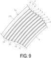
- the fender 1 illustrated in FIG. 9 has a plurality of sets S, each set S (S 1 to S4) including two reinforcing layers 5 layered adjacently.
- the fender 1 includes eight reinforcing layers 5 layered in the cylindrical portion 3a and has four sets S.
- the respective sets S are composed of different reinforcing layers 5.
- the number of sets S is, for example, approximately from 3 to 6 and is preferably plural.
- the fiber cords 7 of each of the reinforcing layers 5 extend in the same direction at a predetermined cord angle A.
- the fiber cords 7 of the reinforcing layers 5 extend in the intersecting direction at a predetermined cord angle A.
- the fiber cords 7 of the reinforcing layers 5 in the sets S1 and S2 extend in the intersecting direction
- the fiber cords 7 of the reinforcing layers 5 in the sets S2 and S3 extend in the intersecting direction
- the fiber cords 7 of the reinforcing layers 5 in the sets S3 and S4 extend in the intersecting direction.
- the fiber cords 7 of the reinforcing layers 5 in the sets S1 and S3 extend in parallel, and the fiber cords 7 of the reinforcing layers 5 in the sets S2 and S4 extend in parallel.
- the fiber cords 7 have a bias structure with the set S as a unit.
- the cord angle A of the fiber cords 7 of each of the reinforcing layers 5, in the cylindrical portion 3a will increase to approximately the stable angle of repose (from 54° to 55°).
- the fiber cords 7 of each of the reinforcing layers 5 extend in the same direction at a predetermined cord angle A. Therefore, a shear force does not substantially act on the coating rubber layer 9 interposed between the reinforcing layers 5 (cord fabrics 6).
- the fiber cords 7 of the reinforcing layers 5 of the sets S layered adjacently in the cylindrical portion 3a extend in the intersecting direction. Therefore, a shear force acts on the coating rubber layer 9 interposed between the sets S, and the coating rubber layer 9 is sheared and deformed. In this manner, when the cylindrical portion 3a is pressurized to the specified internal pressure P from the neutral state, the cord angle A of the fiber cords 7 of each of the reinforcing layers 5 in the cylindrical portion 3a increases to approximately the stable angle of repose (from 54° to 55°), and the cylindrical portion 3a expands and is maintained in a predetermined shape.
- the embodiment of the rubber product is not limited to the fender 1, and may be a marine hose 12 as illustrated in FIGS. 10 and 11 .
- the marine hose 12 includes flange portions 13 at both end portions in the longitudinal direction, and a cylindrical portion 3a extends between the flange portions 13.
- a plurality of reinforcing layers 5 are coaxially layered and embedded between an inner layer 4 and an outer layer 10. Specifications of each of the reinforcing layers 5 are the same as those of the embodiment described above.
- an inner peripheral side region of the inner layer 4 serves as a flow path 12a.
- a buoyant layer is provided between the outer layer 10 and the reinforcing layer 5.
- the marine hose 12 can be produced by molding a cylindrical molded body by a known method using the above-described members and vulcanizing the molded body by a known method. Also in this marine hose 12, as in the embodiment of the fender 1, even if the number of the layered reinforcing layers 5 embedded in the cylindrical portion 3a is reduced, it is easy to ensure sufficient pressure resistance against internal pressure, which is advantageous in improving producibility of the marine hose 12. It is advantageous in suppressing a deterioration in molding processability in producing the marine hose 12.
- each of the fiber cords 7 has a ply structure in which the ply twist count is the same as the cable twist count T.
- the tensile strength F in the direction in which the fiber cords 7 extended was measured for each cord fabric, and the bending hardness H was measured for each cord fabric after the predetermined adhesion treatment.
- fatigue resistance was evaluated using test pieces prepared by vulcanization under the same conditions, as follows. The measurement results and evaluation results are as shown in Table 1.
- the fatigue resistance was evaluated by the disc fatigue strength (Goodrich method) specified in 2.2.2 of JIS L1017 (2002) appendix 1.
- a test piece prepared from the vulcanized reinforcing layer was subjected to a fatigue test in which the test piece was rotated at a strain of ⁇ 10% at a rotation speed of 2400 rpm for 24 hours at room temperature. After the fatigue test, the fiber cord was taken out from the test piece, the tensile strength was measured, and a retention thereof to the tensile strength before the fatigue test was calculated. A high value of the retention indicates superior fatigue resistance.
- the pressure resistance in Table 1 is indicated by ⁇ because it is evaluated to be difficult to ensure sufficient pressure resistance per reinforcing layer when the tensile strength F is less than 4100 N/cm, and is indicated by O because it is evaluated to be possible to ensure sufficient pressure resistance per reinforcing layer when the tensile strength is 4100 N/cm or more.
- ⁇ because it is evaluated to be difficult to ensure sufficient pressure resistance per reinforcing layer when the tensile strength F is less than 4100 N/cm
- O because it is evaluated to be possible to ensure sufficient pressure resistance per reinforcing layer when the tensile strength is 4100 N/cm or more.
- an unvulcanized reinforcing layer having a predetermined width was pasted to a molding drum having a predetermined outer diameter, and the ease of pasting and the degree of deformation of the coating rubber layer after pasting are evaluated.
- the molding processability was evaluated to be excellent and indicated by ⁇ .
- the molding processability was evaluated to be substantially good and indicated by O.
- the molding processability is evaluated to be poor and indicated by ⁇ . That is, the rank of excellent molding processability is in a descending order of ⁇ , ⁇ , and ⁇ .
Landscapes
- Engineering & Computer Science (AREA)
- Mechanical Engineering (AREA)
- Textile Engineering (AREA)
- Chemical & Material Sciences (AREA)
- Composite Materials (AREA)
- General Engineering & Computer Science (AREA)
- Health & Medical Sciences (AREA)
- Oral & Maxillofacial Surgery (AREA)
- Thermal Sciences (AREA)
- Physics & Mathematics (AREA)
- Laminated Bodies (AREA)
- Rigid Pipes And Flexible Pipes (AREA)
- Reinforced Plastic Materials (AREA)
Applications Claiming Priority (2)
| Application Number | Priority Date | Filing Date | Title |
|---|---|---|---|
| JP2022130666A JP2024027678A (ja) | 2022-08-18 | 2022-08-18 | ゴム製品およびその製造方法 |
| PCT/JP2023/016299 WO2024038644A1 (fr) | 2022-08-18 | 2023-04-25 | Produit en caoutchouc et son procédé de production |
Publications (2)
| Publication Number | Publication Date |
|---|---|
| EP4574423A1 true EP4574423A1 (fr) | 2025-06-25 |
| EP4574423A4 EP4574423A4 (fr) | 2025-11-05 |
Family
ID=89941679
Family Applications (1)
| Application Number | Title | Priority Date | Filing Date |
|---|---|---|---|
| EP23854684.0A Pending EP4574423A4 (fr) | 2022-08-18 | 2023-04-25 | Produit en caoutchouc et son procédé de production |
Country Status (6)
| Country | Link |
|---|---|
| US (1) | US12496811B2 (fr) |
| EP (1) | EP4574423A4 (fr) |
| JP (1) | JP2024027678A (fr) |
| KR (1) | KR102886615B1 (fr) |
| CN (1) | CN119546436B (fr) |
| WO (1) | WO2024038644A1 (fr) |
Family Cites Families (8)
| Publication number | Priority date | Publication date | Assignee | Title |
|---|---|---|---|---|
| JPS5439898U (fr) * | 1977-08-24 | 1979-03-16 | ||
| US5595284A (en) * | 1995-05-26 | 1997-01-21 | The Yokohama Rubber Co. Ltd. | Conveyor belt |
| KR0157016B1 (ko) | 1996-06-29 | 1998-11-16 | 양재신 | 자동차의 밸브 리프트 장치 |
| JPH10157016A (ja) | 1996-12-02 | 1998-06-16 | Yokohama Rubber Co Ltd:The | 水中ゴム構造物 |
| JP5565434B2 (ja) * | 2012-04-27 | 2014-08-06 | 横浜ゴム株式会社 | 空気式防舷材 |
| JP5790637B2 (ja) * | 2012-12-20 | 2015-10-07 | 横浜ゴム株式会社 | 空気式防舷材 |
| JP7032928B2 (ja) * | 2017-12-28 | 2022-03-09 | Toyo Tire株式会社 | 空気入りタイヤ |
| JP7180386B2 (ja) * | 2019-01-09 | 2022-11-30 | 横浜ゴム株式会社 | 空気式防舷材 |
-
2022
- 2022-08-18 JP JP2022130666A patent/JP2024027678A/ja active Pending
-
2023
- 2023-04-25 CN CN202380053906.7A patent/CN119546436B/zh active Active
- 2023-04-25 KR KR1020247043562A patent/KR102886615B1/ko active Active
- 2023-04-25 EP EP23854684.0A patent/EP4574423A4/fr active Pending
- 2023-04-25 US US18/998,279 patent/US12496811B2/en active Active
- 2023-04-25 WO PCT/JP2023/016299 patent/WO2024038644A1/fr not_active Ceased
Also Published As
| Publication number | Publication date |
|---|---|
| US12496811B2 (en) | 2025-12-16 |
| EP4574423A4 (fr) | 2025-11-05 |
| KR102886615B1 (ko) | 2025-11-14 |
| WO2024038644A1 (fr) | 2024-02-22 |
| CN119546436B (zh) | 2025-11-25 |
| CN119546436A (zh) | 2025-02-28 |
| US20250262845A1 (en) | 2025-08-21 |
| JP2024027678A (ja) | 2024-03-01 |
| KR20250008992A (ko) | 2025-01-16 |
Similar Documents
| Publication | Publication Date | Title |
|---|---|---|
| EP0335588B2 (fr) | Pneumatique radial | |
| US11331953B2 (en) | Assembly comprising a partially breakable fabric and a supporting structure | |
| US11046112B2 (en) | Assembly for tire including impregnated woven or knitted fabric(s) and a sacrificial holder | |
| US11325418B2 (en) | Tire assembly comprising a breakable structure and a supporting structure | |
| EP2537686B1 (fr) | Pneumatique | |
| EP2380756A1 (fr) | Pli de carcasse pour pneu | |
| EP0855964B1 (fr) | Tissu en nappe pour pneumatique a carcasse encablee acier de faible epaisseur et de petit diametre et procede de jonctionnement a recouvrement du tissu | |
| EP2380754A2 (fr) | Corde hybride dans une nappe de renforcement de sommet pour pneu | |
| CN101517158A (zh) | 钢丝帘线、橡胶钢丝帘线复合体以及轮胎 | |
| EP2937465A1 (fr) | Garde-boue de pneumatique | |
| EP2806057B1 (fr) | Câble hybride et pneu comprenant un tel câble | |
| US7032638B2 (en) | Tire with a protective crown ply made of very high twist aramid fiber | |
| US11821114B2 (en) | Actuator | |
| EP4574423A1 (fr) | Produit en caoutchouc et son procédé de production | |
| EP4477929B1 (fr) | Procédé de détermination de spécifications d'un matériau renforcé par des fibres pour des tuyaux souples marins, et procédé de fabrication d'un tuyau souple marin | |
| JPS61132402A (ja) | 改善されたタイヤ | |
| WO2007094222A1 (fr) | Cable d'acier, cable composite d'acier-caoutchouc et pneumatique | |
| EP2380755B1 (fr) | Nappe recouvrant l'armature de sommet pour pneu | |
| JP4593286B2 (ja) | 航空機タイヤ | |
| US12594793B2 (en) | Tire comprising a pair of flexible bead cores | |
| JP2005219550A (ja) | 空気入りラジアルタイヤ |
Legal Events
| Date | Code | Title | Description |
|---|---|---|---|
| STAA | Information on the status of an ep patent application or granted ep patent |
Free format text: STATUS: THE INTERNATIONAL PUBLICATION HAS BEEN MADE |
|
| PUAI | Public reference made under article 153(3) epc to a published international application that has entered the european phase |
Free format text: ORIGINAL CODE: 0009012 |
|
| STAA | Information on the status of an ep patent application or granted ep patent |
Free format text: STATUS: REQUEST FOR EXAMINATION WAS MADE |
|
| 17P | Request for examination filed |
Effective date: 20250317 |
|
| AK | Designated contracting states |
Kind code of ref document: A1 Designated state(s): AL AT BE BG CH CY CZ DE DK EE ES FI FR GB GR HR HU IE IS IT LI LT LU LV MC ME MK MT NL NO PL PT RO RS SE SI SK SM TR |
|
| A4 | Supplementary search report drawn up and despatched |
Effective date: 20251006 |
|
| RIC1 | Information provided on ipc code assigned before grant |
Ipc: B32B 25/10 20060101AFI20250929BHEP Ipc: B29C 35/02 20060101ALI20250929BHEP Ipc: B29C 70/22 20060101ALI20250929BHEP Ipc: B29C 70/30 20060101ALI20250929BHEP Ipc: F16L 11/08 20060101ALI20250929BHEP Ipc: B32B 5/02 20060101ALI20250929BHEP Ipc: B32B 1/08 20060101ALI20250929BHEP Ipc: B32B 5/12 20060101ALI20250929BHEP |
|
| DAV | Request for validation of the european patent (deleted) | ||
| DAX | Request for extension of the european patent (deleted) |