EP3616496A1 - Engin de travail agricole - Google Patents
Engin de travail agricole Download PDFInfo
- Publication number
- EP3616496A1 EP3616496A1 EP19178626.8A EP19178626A EP3616496A1 EP 3616496 A1 EP3616496 A1 EP 3616496A1 EP 19178626 A EP19178626 A EP 19178626A EP 3616496 A1 EP3616496 A1 EP 3616496A1
- Authority
- EP
- European Patent Office
- Prior art keywords
- crop
- speed
- processing unit
- image processing
- images
- Prior art date
- Legal status (The legal status is an assumption and is not a legal conclusion. Google has not performed a legal analysis and makes no representation as to the accuracy of the status listed.)
- Granted
Links
Images

Classifications
-
- A—HUMAN NECESSITIES
- A01—AGRICULTURE; FORESTRY; ANIMAL HUSBANDRY; HUNTING; TRAPPING; FISHING
- A01D—HARVESTING; MOWING
- A01D41/00—Combines, i.e. harvesters or mowers combined with threshing devices
- A01D41/12—Details of combines
- A01D41/127—Control or measuring arrangements specially adapted for combines
- A01D41/1271—Control or measuring arrangements specially adapted for combines for measuring crop flow
-
- A—HUMAN NECESSITIES
- A01—AGRICULTURE; FORESTRY; ANIMAL HUSBANDRY; HUNTING; TRAPPING; FISHING
- A01D—HARVESTING; MOWING
- A01D41/00—Combines, i.e. harvesters or mowers combined with threshing devices
- A01D41/12—Details of combines
- A01D41/14—Mowing tables
- A01D41/141—Automatic header control
-
- G—PHYSICS
- G06—COMPUTING OR CALCULATING; COUNTING
- G06T—IMAGE DATA PROCESSING OR GENERATION, IN GENERAL
- G06T7/00—Image analysis
- G06T7/20—Analysis of motion
- G06T7/246—Analysis of motion using feature-based methods, e.g. the tracking of corners or segments
- G06T7/248—Analysis of motion using feature-based methods, e.g. the tracking of corners or segments involving reference images or patches
-
- G—PHYSICS
- G06—COMPUTING OR CALCULATING; COUNTING
- G06T—IMAGE DATA PROCESSING OR GENERATION, IN GENERAL
- G06T7/00—Image analysis
- G06T7/70—Determining position or orientation of objects or cameras
- G06T7/73—Determining position or orientation of objects or cameras using feature-based methods
- G06T7/74—Determining position or orientation of objects or cameras using feature-based methods involving reference images or patches
-
- G—PHYSICS
- G06—COMPUTING OR CALCULATING; COUNTING
- G06V—IMAGE OR VIDEO RECOGNITION OR UNDERSTANDING
- G06V20/00—Scenes; Scene-specific elements
- G06V20/50—Context or environment of the image
- G06V20/56—Context or environment of the image exterior to a vehicle by using sensors mounted on the vehicle
-
- G—PHYSICS
- G06—COMPUTING OR CALCULATING; COUNTING
- G06T—IMAGE DATA PROCESSING OR GENERATION, IN GENERAL
- G06T2207/00—Indexing scheme for image analysis or image enhancement
- G06T2207/30—Subject of image; Context of image processing
- G06T2207/30181—Earth observation
- G06T2207/30188—Vegetation; Agriculture
-
- G—PHYSICS
- G06—COMPUTING OR CALCULATING; COUNTING
- G06T—IMAGE DATA PROCESSING OR GENERATION, IN GENERAL
- G06T2207/00—Indexing scheme for image analysis or image enhancement
- G06T2207/30—Subject of image; Context of image processing
- G06T2207/30248—Vehicle exterior or interior
- G06T2207/30252—Vehicle exterior; Vicinity of vehicle
Definitions
- the invention relates to an agricultural working machine, in particular a harvesting machine, according to the preamble of claim 1 and a method for operating an agricultural working machine according to the preamble of claim 23.
- Agricultural machines which include, in particular, self-propelled harvesting machines such as combine harvesters and forage harvesters, regularly have a crop recovery arrangement as an attachment, with which crops in the field can be separated and taken up for further processing in the combine harvester.
- a crop recovery arrangement in turn regularly has a large number of individual components which can be operated with different parameters. Examples of such components in a combine are a crop pick-up device in the form of a reel, a crop cutting device in the form of a cutting table with a cutter bar, a crop conveying device in the form of a screw conveyor, in particular a transverse screw conveyor, and a crop pick-up device in the form of an inclined conveyor.
- the position (cutting height, position) and speed of the reel as well as the speed of the cross auger and the feeder can be set.
- the crop flow can be influenced within the crop recovery arrangement.
- the driving speed of the harvesting machine has a further influence on the crop flow within the crop recovery arrangement, since in this way the amount of harvested crop that is processed by the crop recovery arrangement is influenced.
- the driver of the agricultural machine must monitor the crop flow both within the crop recovery arrangement and also within the combine harvester. For example, he must make sure that the crop flow speed is as uniform as possible within the front attachment and the further course within the combine harvester, since if the crop flow is uneven, the vehicle speed and thus crop harvesting may have to be reduced in order to avoid a crop jam. If a crop jam occurs, the harvesting process must canceled and an elaborate removal of the estate jam in the front attachment or in the combine harvester is carried out. The time required for this significantly affects the profitability of the harvesting operation.
- the EP 3 300 019 A1 known to provide a control device with a sensor unit and an image processing unit, via which the crop flow is monitored using the optical flow method.
- the sensor device has, for example, two cameras, which are directed from the driver's cab onto the crop recovery arrangement and there comprise individual sections of the components and the crop stream.
- the sensor device generates an image sequence, ie a large number of successive images.
- two successive images are grouped into one image pair, position shifts of intensity patterns, that is to say of pixels or pixel groups, between the images of the respective image pair being determined.
- the intensity patterns are not necessarily formed by objects or specific crop characteristics, but generally by pixels or groups of pixels in the image, the position of which changes from one image to the next image.
- the invention is based on the problem of designing and developing an agricultural working machine in such a way that the monitoring of an attachment is further improved with regard to accuracy, reliability and timeliness.
- a region of the same characteristic is, for example, the non-harvested field stock in the direction of travel in front of the header, another region of the same characteristic is, for example, the harvested field stock (stubble field) behind the header.
- Crop flow regions of the same characteristic can also be included, with for example a region of the same characteristic of the crop flow within the crop receiving device, in particular reel, and another region of the same characteristic of the crop flow vertically above the crop cutting device, in particular vertically above the cutting table, in particular in the area between the crop receiving device or reel and the crop conveyor, in particular screw conveyor, is formed.
- further areas are components of the front attachment which have a surface section of a machine part of the component that can be sensed by the sensor unit.
- Corresponding components are, for example, the crop receiving device, in particular the reel, the crop cutting device, in particular the cutting table, the crop conveying device, in particular screw conveyor, and / or the crop feeding device, in particular the inclined conveyor, of a crop recovery arrangement, for example a combine harvester.
- Each of these areas is accordingly defined by the presence of a surface section of a machine part of a component of the header.
- properties of the crop flow for example crop flow rates of the crop stream or sections thereof and / or crop accumulation, are recognized.
- process sequences in the agricultural working machine are then controlled and / or regulated in a subsequent or simultaneously running control and / or regulation process. Due to the division into regions and components, the behavior of a header and the crop flow along it can be viewed and analyzed in a particularly differentiated manner. Accordingly, the monitoring of an attachment, in particular a crop recovery arrangement, is further improved with regard to accuracy, reliability and timeliness.
- control device is configured to recognize regions of the same characteristic, components of the header and properties of the crop flow, and configured that the respectively recognized, that is to say the recognized regions of the same characteristic, the recognized components of the header and / or the recognized To use properties of the crop flow to control and / or regulate process sequences in the agricultural machine.
- “Recognizing” the regions and components in question preferably does not merely mean determining regions, but also unambiguously identifying the respective region, that is to say assigning the region to a function and / or property. Accordingly, for example, when the region with the field inventory in front of the front device is identified, it is meant that a region is first detected or located by means of sensory detection and image processing and then this region as a specific region with a specific function and / or property, for example specifically is identified as a field stock in front of the front attachment. The individual areas can thus be distinguished from one another not only on the basis of their position but also on the basis of their function and / or property. This enables differentiated movements to be differentiated.
- Claim 2 defines various preferred regions that the image processing unit can determine and in particular identify. According to the embodiment according to claim 3, identification is possible on the basis of stored identification data characterizing the respective region (region or component). For example, certain dimensions or positions of a region or component can be stored in a data memory as identification data within or outside the front device, on the basis of which the region or component can then be identified as a specific region or component.
- the image processing unit can use different methods based on the images generated by the sensor unit. For example, the image processing unit can use the method of determining the speed map, also known as the method of optical flow, which will be explained in more detail below. Additionally or alternatively, it can use the line recognition method, which will also be explained below. Additionally or alternatively, it can also use at least one color filter. In this way, an object detection can also be carried out, in which biomass in particular is distinguished on the one hand from mechanical objects on the other hand (claim 5).
- the speed map determination or method of the optical flow is a known image processing method and is based on the determination and analysis of intensity patterns (pixels or groups of pixels) in successive images of an image sequence.
- an image sequence is generated, in particular via one or more cameras, that is to say a plurality of successive images.
- Two successive images, in particular two immediately successive images, of the image sequence are grouped into one image pair, position shifts of intensity patterns, that is to say of pixels or pixel groups, between the images of the respective image pair being determined. If the time period between the images of the pair of images is known, these position shifts in the intensity patterns can be used to infer the speed at which the intensity patterns move.
- the direction in which the intensity patterns move can also be determined from this.
- the optical flow method thus includes the pixel-based generation of information on the one hand about speeds of intensity patterns and on the other hand about their directions of movement.
- the speeds of several intensity patterns can be summarized for each image pair and each image sequence consisting of several image pairs to form speed maps, which are generally also referred to as optical flow.
- the image processing unit can also differentiate the individual areas from one another.
- Claims 10 to 13 relate to the method of line detection, which can be used additionally or alternatively.
- This is an image processing method in which an edge detection is first carried out for the respective image, from which an edge image is generated.
- edge detection flat areas in a digital image are separated from one another if they differ sufficiently in color or gray value, brightness or texture along straight or curved lines.
- edge detection or generation of an edge image is carried out in particular by means of the Canny algorithm known per se.
- straight lines are determined and displayed or highlighted in the edge image via line detection.
- Such a straight line detection is preferably carried out using the known Hough transformation.
- contours of components or their machine parts can be recognized, which also makes it possible to distinguish individual areas (regions or components) from one another and, if necessary, also to identify them.
- the reel can in particular be highlighted and thus identified in a digital image which, for example, depicts a harvesting arrangement of a combine harvester, since this is represented by many straight lines in a two-dimensional image.
- the determination of geometric parameters of the respective component for example the inclination and / or height of the component, is also made possible.
- line patterns result in each image, namely patterns from the straight line or lines determined by means of the line detection.
- position shifts of line patterns that is to say of lines or line groups, between the images of the respective image pair can then be determined, similarly to the method of determining the speed map.
- the time span between the images of the pair of images is known, these position shifts of the line patterns can also be used to infer the speed at which the line patterns move.
- the direction in which the line patterns move can also be determined.
- the line detection thus includes the line-based generation of information on the speeds of line patterns and, if applicable, on their directions of movement. In addition to the detection of the areas, it is also possible to determine the speed at which lines or contours of components move between two successive images.
- Claims 14 to 19 relate to the possibility of determining reference regions or reference surface sections with which another region which is currently to be analyzed can be compared. Such a comparison between two regions, one of which serves as a basis (reference), makes it possible to infer properties, in particular the speed, in the region currently to be analyzed. The same applies not only to regions, but also to components and their surface sections.
- the reference speed can be determined, for example, by relating the driving speed of the agricultural working machine, which is known or can be detected precisely by corresponding sensors, to a speed of the field population of a region calculated from the shift amounts. The reference speed is then a speed corresponding to the driving speed in a certain ratio.
- the speed of a component for example the reel, which is known or can be detected precisely by corresponding sensors, can be related to the speed of the surface section calculated from the displacement amounts.
- the reference speed is then a speed corresponding to the speed in a certain ratio.
- Such reference speeds can then also be used to infer speeds in other regions or of other surface sections of components.
- the attachment is a crop recovery arrangement for separating and picking up crop from a field, which has as components a crop pick-up device, a crop cutting device, a crop conveying device and a crop pick-up device.
- this is a crop recovery arrangement from a combine harvester or forage harvester.
- the speed of a surface section of a machine part of the respective component can also be determined using a marker, the marker then forming the surface section.
- a characteristic serves as a marker Place, for example edge or surface, on the respective machine part or a separately applied marking.
- the marker then represents the surface section that is sensed by the sensor unit to determine the speed.
- various sensors can be provided for sensory detection of the crop flow and / or attachment, in particular at least one optical sensor, for example one camera or several cameras.
- an optical sensor is particularly useful when the method of determining the speed map (optical flow method) is to be used.
- the sensor unit can also have at least one lidar sensor, at least one radar sensor and / or at least one ultrasonic sensor. All of the aforementioned sensors are also suitable for the application of the line detection method.
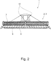
- the proposed agricultural working machine 1 which here is, for example, a combine harvester, has as a header 2 a crop recovery arrangement, which is formed here by a cutting unit 3 and is arranged at the front of the agricultural working machine 1 in the direction of travel.
- the crop recovery arrangement 2 or the cutting unit 3 serves to separate and pick up crop 4 from a field stock 5, the crop 4 being fed to the agricultural machine 1 for further processing by a plurality of further working elements 6.
- the further explanations using the example of the crop recovery arrangement 2 are not limited to this application, but also apply mutatis mutandis to other attachments 2, for example a header of a forage harvester.
- the crop recovery arrangement 2 has as components C, D, E, F here and preferably in any case a crop pick-up device 7 in the form of a reel, a crop cutting device 8 in the form of a cutting table with a cutter bar, a crop feed device 9 downstream of this in terms of process technology, in the form of a screw conveyor, in particular a transverse screw conveyor, and one of these, in turn, process-related crop feeder 10 in the form of an inclined conveyor.
- the crop 4 is a crop flow (in Fig. 1 and 3a ) represented by arrows) through the crop recovery arrangement 2.
- the crop 4 is picked up and held via the crop pickup device 7 or reel, while it is separated from the crop cutting device 8 becomes.
- the separated crop 4 is then moved against the crop conveyor device 9, which preferably runs transversely here, and is conveyed by it in the transverse direction, that is to say transversely to the direction of travel, to the center of the vehicle, where it is then drawn in by the crop feed device 10 and conveyed further into the interior of the agricultural working machine 1 becomes.
- the agricultural working machine 1 also has a control device 11 which, here and preferably, serves to control the other working elements 6 of the agricultural working machine 1 in addition to the components C, D, E, F of the crop harvesting arrangement 2.
- the control can include speed or speed controls and / or height adjustments and / or position adjustments.
- the driving speed of the agricultural working machine 1 is controlled.
- the control device 11 here and preferably has a sensor unit 12 in the form of two cameras, the sensor unit 12 being arranged in the front area of the agricultural working machine 1, in particular on and / or within the driver's cab of the agricultural working machine 1, and serving for the optical detection of the crop flow.
- the area of optical detection is symbolic here in the Fig. 1 and 2 shown in dashed lines.
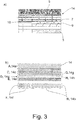
- control device 11 has an image processing unit 13 for processing images 14, one of which is shown in FIG Fig. 3a ) is shown.
- the images 14 are generated by the sensor unit 12 based on the optically recorded crop flow.
- control device 11 here and preferably has a data output unit 15, which in particular comprises a display device 15a and is used for the optional output or display of the images 14 processed by the image processing unit 13.
- control device 11 is configured to recognize regions A, B, G, H of the same characteristic, components C, D, E, F of the front attachment 2 or here the crop recovery arrangement and properties of the crop flow.
- Regions A, B, G, H of the same characteristic on the one hand and components C, D, E, F of the front attachment 2 on the other represent areas in and around the front attachment 2 which can be detected by the sensor unit 12 and which are particularly suitable as the basis for a differentiated consideration and analysis of the crop flow.
- a region A of the same characteristic is, in the exemplary embodiment shown and to that extent preferred, the non-harvested field stock 5 in the direction of travel before the crop harvesting arrangement 2.
- Another region B of the same characteristic is here the harvested field population 5 in the form of the stubble field behind the crop harvesting arrangement 2.
- Yet another region The same characteristic is formed here by the crop flow within the crop receiving device 7 in the form of the reel.
- a further region H of the same characteristic is formed vertically above the crop cutting device 8 in the form of the cutting table, here in the area between the reel and the crop conveying device 9 in the form of the screw conveyor.
- components C, D, E, F of the crop recovery arrangement 2 are formed in the exemplary embodiment shown here. These areas each have at least one surface section of a machine part of the respective component C, D, E, F that can be sensed by the sensor unit 12.
- Corresponding components C, D, E, F are here the crop receiving device 7 in the form of the reel, the crop cutting device 8 in the form of the cutting table, the crop conveying device 9 in the form of the screw conveyor and the crop feeding device 10 in the form of the inclined conveyor.
- the list of components in the proposed sense is not to be understood as conclusive.
- the control device 11 also performs, in particular via the image processing unit 13, a recognition of properties of the crop flow, for example crop flow rates of the crop stream or sections thereof and / or of a crop jam.
- control device 11 uses the respectively recognized regions and components A-H as well as the recognized properties of the crop flow to control and / or regulate process sequences in the agricultural working machine 1.
- parameters of components C, D, E, F of the crop recovery arrangement 2 and / or parameters of further working elements 6 of the agricultural working machine 1, here the combine harvester can then be adapted. Due to the division into regions and components A-H, the crop recovery arrangement 2 and the crop flow can be viewed and analyzed in a very differentiated manner, which in turn optimizes the monitoring of the crop recovery arrangement 2 and the crop flow.
- the regions and components AH are first detected or ascertained. Then at least some of the regions and components AH are specifically identified by comparing each of these areas, preferably with associated identification data that characterizes them (for example dimensions, positions, etc.), which identification data are stored in particular in the image processing unit 13.
- the field stock 5 in front of the crop harvesting arrangement 2 can be determined as a region A and then in particular identified as such, that is to say as the field stock 5 in front of the crop harvesting arrangement 2.
- the field stock 5 behind the crop recovery arrangement 2 can be determined as a region B, for example, and then specifically identified as the field inventory 5 behind the crop recovery arrangement 2. Basically, this is also possible for components.
- the crop pick-up device 7 or reel determines the crop pick-up device 7 or reel as a component C and then to identify it specifically as such, that is to say as the crop pick-up device 7 or reel.
- it can be provided, as a component D, the crop cutting device 8 or the cutting table to determine and in particular to identify as such. Further examples are also conceivable.
- the regions and components A-H are determined by means of the image processing unit 13, specifically by determining assigned image areas 14a-14h in the images 14 generated by the sensor unit 12, which will be explained in more detail below.
- Various image processing methods individually or in combination, can be used for this purpose, two of which are particularly preferred, namely the method of determining the speed map and the method of line detection are explained in more detail below. In principle, these methods can also be combined with other methods for optimizing the image data, for example by using at least one color filter, a noise reduction, a change in contrast, a change in brightness or the like.
- an object detection can then be carried out, which preferably comprises a distinction between biomass on the one hand and mechanical objects on the other hand, and / or which differentiates one or more regions A, B, G, H on the one hand and one or more surface sections of Machine parts of components C, D, E, F on the other hand includes.
- the image processing unit 13 can create a speed map, also referred to as an optical flow, based on the images 14 generated by the sensor unit 12, here and preferably by one or more cameras.
- the optical flow is the pixel-wise movement in the image area given by an image frequency, also referred to as a flow field.
- the frame rate is in turn defined with the pixel position and the point in time.
- the movement is a vector field in an image 14, which is generated by superimposing two images 14 of an image pair, and describes the time-dependent shift of a pixel or a pixel group, also referred to below as intensity pattern, from one to the next image 14 of the image pair.
- the image composed of the two individual images 14 can be revised beforehand by the image processing unit 13, as is shown, for example, in FIG EP 3 300 019 A1 is described in detail.
- the Lucas-Kanade method in which the image resolution of the images is reduced, may be mentioned here merely as an example.
- the resulting image is then used to create the speed map.
- the speed map shows the crop flow velocities, in particular of crop particles, and the velocities of surface sections of machine parts of components C, D, E, F of crop recovery arrangement 2.
- the image processing unit 13 groups two successive, in particular two immediately successive, images 14 of an image sequence generated by the sensor unit 12 into a pair of images.
- a time span between the images 14 of the respective image pair is captured by the image processing unit 13. Additionally or alternatively, a time period can be specified by the image processing unit 13.
- Each image 14 of the respective image pair has an intensity pattern, that is to say a pixel or a group of pixels.
- the image processing unit 13 uses the intensity patterns between the images 14 of the respective image pair to determine position shifts which include shift amounts and shift directions.
- the amounts of displacement and directions of displacement for each pair of images are combined as vectors of a vector field of the respective pair of images.
- Speeds are then calculated by the image processing unit 13 from the shift amounts of the intensity patterns between the images 14 of the respective image pair and the time span between the images 14 of the respective image pair.
- the speeds are, as previously indicated, crop flow velocities and / or velocities of surface sections of the components C, D, E, F of the crop recovery arrangement 2.
- the respective speed of a surface section of a machine part of the respective component C, D, E, F can also be determined using a marker , the marker then forming the surface section which is sensed for determining the speed of the surface section of this component C, D, E, F.
- said detection of properties of the crop flow can take place, for example the detection of an impending crop jam.
- the images 14 generated by the sensor unit 12 are subdivided by the image processing unit 13 into image areas, each of which corresponds to one of the regions and components AH mentioned.
- the sensor unit 12 detects the field stock 5 both in front of the crop recovery arrangement 2 and behind it.
- the sensor unit 12 here and preferably detects the crop receiving device 7, the crop cutting device 8, the crop conveying device 9 and the crop feeding device 10. The crop flow within the crop pickup device 7 and the crop stream vertically above the crop cutting device 8, here between the crop pickup device 7 and the crop conveying device 9, are also detected.
- the image areas shown in the images 14 are now as described, here and preferably an image area 14a with the field stock 5 in front of the crop recovery arrangement 2, an image area 14b with the field stock 5 behind the crop recovery arrangement 2 , an image area 14c with the crop receiving device 7, an image area 14d with the crop cutting device 8, an image area 14e with the crop conveying device 9, an image area 14f with the crop feeding device 10, an image area 14g with the crop flow inside the crop receiving device 7 and / or an image area 14h the crop flow vertically above the crop cutting device 8, in particular in the area between the crop receiving device 7 and the crop conveying device 9.
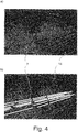
- individual image areas can also be determined and / or highlighted by the method of line detection, which is shown in Fig. 4 is shown in the form of the reel by way of example with the aid of the crop pickup device 7
- the sensor unit 12 for the sensory detection of the crop recovery arrangement 2 can have at least one lidar, radar and / or ultrasonic sensor.
- an edge image is then first generated for the respective image 14, here and preferably by means of the Canny algorithm.
- a straight line detection is then carried out, in which straight lines are determined in the edge image, here and preferably by means of the Hough transformation, the straight lines, such as Fig. 4b ) shows can be highlighted graphically.
- the here in Fig. 4b ) Graphically highlighted lines define one of the described and recognizable components C, D, E, F, here the crop pick-up device 7 in the form of the reel.
- the image processing unit 13 groups two successive, in particular two immediately successive, images 14 of an image sequence generated by the sensor unit 12 into one image pair, a period of time between the images 14 of the respective image pair is captured by the image processing unit 13 and / or is predetermined, and wherein each image 14 of the respective image pair has a line pattern from one or more straight lines.
- the line pattern is the line or lines obtained by the straight line detection described. This line pattern is in Fig. 4b ) highlighted brightly.
- position shifts of the line patterns between two images 14 of a respective image pair can also be determined here, which include amounts of displacement and in particular directions of displacement of the line patterns. These amounts of displacement and directions of displacement can also be used for each pair of images are summarized as vectors of a vector field of the respective image pair.
- the method of line recognition enables, in addition to the detection of the respective component C, D, E, F, here the reel, and their speed behavior, the determination of geometric parameters of the respective component, for example the inclination and / or height, in a simple and quick manner Component.
- the possibility is also provided of analyzing certain of the aforementioned regions and components A-H relative to one another in order to determine criteria and physical parameters.
- the image processing unit 13 can specify one or more regions A, B, G, H each as a reference region and / or one or more surface sections of machine parts of the components C, D, E, F each as a reference surface section.
- the respective reference region and / or the respective reference surface section can then be used as a basis (reference) for a comparison with another region A, B, G, H and / or another reference surface section.
- the actual speed is known or can be determined precisely for certain regions or surface sections, for example using speed sensors, and this speed can be used to determine the speed using the image processing method (eg determining the speed map and / or line detection) to correct or calibrate the calculated speeds.
- the speeds calculated using the image processing methods are always dependent on the attachment and machine settings as well as the ambient conditions and are therefore generally different for each application.
- a value for the speed in other regions or surface sections can also be specified.
- the speed of the reel is regularly known, so that a value for the speed of the assigned surface section of this component C is also fixed in the plane of the images 14 generated.
- This speed or this speed value forms a reference speed or a reference speed value.
- a speed value of the assigned surface section has been calculated on the basis of the aforementioned displacement amounts.
- the ratio between the two speed values that is to say the reference speed value and the speed value calculated on the basis of the displacement amounts, can now be calculated. Since the same ratio also exists in other regions and surface sections, the actual speed for the respective other region or for the respective other surface section can be inferred from the speed calculated on the basis of the displacement amounts mentioned for the respective other region or for the respective other surface section .
- the image processing unit can thus be configured to use the method of determining the speed map and / or by means of the method of line detection to recognize a crop pickup device 7, in particular the reel, of the front attachment 2 as a component C and using its actual (known) speed and by comparison determine this reference speed at the speed calculated (on the basis of the displacement amounts) for the surface section of the machine part of component C.
- the driving speed can also be used, which is also known.
- a value for the speed of the field stand 5 relative to the crop recovery arrangement 2 is thus also fixed. Since the field population 5 is recorded in regions A, B, a value for the speed in these regions A, B is also fixed in the plane of the images 14 generated. This speed or this speed value also forms a reference speed or a reference speed value.
- the image processing unit can be configured to recognize a region A with the field inventory 5 in front of the front attachment 2 or a region B with the field inventory 5 behind the front attachment 2 by means of the method of determining the speed map and / or by means of the line recognition method and using this to determine the actual (known) driving speed of the agricultural working machine 1 and by comparing this driving speed with the speed (based on the displacement amounts) calculated for the field stock 5 of the respective region A, B a reference speed.
- the image processing unit 13 is configured by comparing a speed determined in a region A, B, D, H or a component C, D, E, F with the method of determining the speed map and / or using the method for line detection Reference speed to calculate the actual speed of the crop 4 or crop 5 in the region A, B, D, H or the actual speed of the component C, D, E, F.
- the image processing unit 13 can thus determine the crop flow rate in this region by comparing a region A, B, G, H with one or more reference regions or one or more reference surface sections.
- the image processing unit 13 can also determine the speed of the component C, D, E, F by comparing a surface section of a machine part of a component C, D, E, F with one or more reference regions or one or more reference surface sections.
Landscapes
- Engineering & Computer Science (AREA)
- Theoretical Computer Science (AREA)
- Physics & Mathematics (AREA)
- General Physics & Mathematics (AREA)
- Life Sciences & Earth Sciences (AREA)
- Environmental Sciences (AREA)
- Computer Vision & Pattern Recognition (AREA)
- Multimedia (AREA)
- Guiding Agricultural Machines (AREA)
- Outside Dividers And Delivering Mechanisms For Harvesters (AREA)
- Health & Medical Sciences (AREA)
- Artificial Intelligence (AREA)
- Computing Systems (AREA)
- Databases & Information Systems (AREA)
- Evolutionary Computation (AREA)
- General Health & Medical Sciences (AREA)
- Medical Informatics (AREA)
- Software Systems (AREA)
Applications Claiming Priority (1)
| Application Number | Priority Date | Filing Date | Title |
|---|---|---|---|
| DE102018121031.0A DE102018121031A1 (de) | 2018-08-29 | 2018-08-29 | Landwirtschaftliche Arbeitsmaschine |
Publications (2)
| Publication Number | Publication Date |
|---|---|
| EP3616496A1 true EP3616496A1 (fr) | 2020-03-04 |
| EP3616496B1 EP3616496B1 (fr) | 2023-08-09 |
Family
ID=66776156
Family Applications (1)
| Application Number | Title | Priority Date | Filing Date |
|---|---|---|---|
| EP19178626.8A Active EP3616496B1 (fr) | 2018-08-29 | 2019-06-06 | Engin de travail agricole |
Country Status (3)
| Country | Link |
|---|---|
| US (1) | US11470776B2 (fr) |
| EP (1) | EP3616496B1 (fr) |
| DE (1) | DE102018121031A1 (fr) |
Cited By (3)
| Publication number | Priority date | Publication date | Assignee | Title |
|---|---|---|---|---|
| DE102022107805A1 (de) | 2022-04-01 | 2023-10-05 | Deere & Company | Maschine zur Futterernte mit vorausschauender Ansteuerung |
| WO2024201161A1 (fr) * | 2023-03-30 | 2024-10-03 | Agco International Gmbh | Surveillance d'écoulement de matériau |
| EP4573876A1 (fr) * | 2023-12-22 | 2025-06-25 | CNH Industrial Belgium N.V. | Bec cueilleur de maïs à résolution de cartographie de rendement améliorée |
Families Citing this family (18)
| Publication number | Priority date | Publication date | Assignee | Title |
|---|---|---|---|---|
| JP7034866B2 (ja) * | 2018-08-20 | 2022-03-14 | 株式会社クボタ | 収穫機 |
| CN114513949A (zh) * | 2019-12-09 | 2022-05-17 | 精密种植有限责任公司 | 用于收割的方法和成像系统 |
| US12137630B2 (en) | 2019-12-23 | 2024-11-12 | Cnh Industrial America Llc | Sensor assembly for an agricultural header |
| US11533851B2 (en) * | 2019-12-23 | 2022-12-27 | Cnh Industrial America Llc | Reel assembly for an agricultural header |
| US12422847B2 (en) * | 2020-10-09 | 2025-09-23 | Deere & Company | Predictive agricultural model and map generation |
| US12022772B2 (en) * | 2021-01-22 | 2024-07-02 | Deere & Company | Agricultural header control |
| US11870973B2 (en) | 2021-07-27 | 2024-01-09 | Deere & Company | Camera calibration tool |
| DE102021120368A1 (de) * | 2021-08-05 | 2023-02-09 | Claas Selbstfahrende Erntemaschinen Gmbh | Landwirtschaftliche Maschine mit kameraüberwachter Komponente |
| DE102022101747B4 (de) | 2022-01-26 | 2024-07-25 | Jörn Strauß | Erntefahrzeug sowie Verfahren zum Betreiben und Kalibrieren eines Erntefahrzeugs |
| US12477984B2 (en) * | 2022-07-29 | 2025-11-25 | Cnh Industrial America Llc | Agricultural system and method for determining header throughput of a harvester |
| DE102022128699A1 (de) | 2022-10-28 | 2024-05-08 | Claas Selbstfahrende Erntemaschinen Gmbh | Landwirtschaftliche Arbeitsmaschine |
| US20240142980A1 (en) * | 2022-10-31 | 2024-05-02 | Deere & Company | Agronomy Data Utilization System And Method |
| EP4371389A1 (fr) * | 2022-11-15 | 2024-05-22 | CNH Industrial Belgium N.V. | D'une opération de récoltesystème et procédé de surveillance basée sur un capteur |
| WO2024261545A1 (fr) * | 2023-06-20 | 2024-12-26 | Agco International Gmbh | Système de commande et procédé de commande pour commander le fonctionnement d'une machine de récolte agricole |
| CN117315514B (zh) * | 2023-11-27 | 2024-03-19 | 华南农业大学 | 一种无人农机人机协作模式工作区域划分方法 |
| US20250185538A1 (en) * | 2023-12-11 | 2025-06-12 | Deere & Company | Header monitoring system |
| US12520758B2 (en) | 2024-05-23 | 2026-01-13 | Deere & Company | Controlling an agricultural harvester based upon material other than grain (MOG) content characteristics |
| US12687860B2 (en) | 2024-07-09 | 2026-07-21 | Deere & Company | Harvest readiness determination using drone with crop engaging component |
Citations (3)
| Publication number | Priority date | Publication date | Assignee | Title |
|---|---|---|---|---|
| DE102016202628A1 (de) * | 2016-02-19 | 2017-08-24 | Deere & Company | Sensoranordnung zur Funktionsüberwachung eines Erntevorsatzes |
| EP3300019A1 (fr) | 2016-09-27 | 2018-03-28 | CLAAS Selbstfahrende Erntemaschinen GmbH | Surveillance d'écoulement de produit dans un dispositif de collecte de récolte |
| EP3552474A1 (fr) * | 2018-04-09 | 2019-10-16 | Deere & Company | Système pour commander un paramètre opérationnel d'une moissonneuse |
Family Cites Families (7)
| Publication number | Priority date | Publication date | Assignee | Title |
|---|---|---|---|---|
| DE10129135B4 (de) * | 2001-06-16 | 2013-10-24 | Deere & Company | Einrichtung zur Positionsbestimmung eines landwirtschaftlichen Arbeitsfahrzeugs sowie ein landwirtschaftliches Arbeitsfahrzeug mit dieser |
| DE10342922A1 (de) * | 2003-09-15 | 2005-05-19 | Claas Selbstfahrende Erntemaschinen Gmbh | Häcksel- und Verteilvorrichtung |
| DE102014113965A1 (de) * | 2014-09-26 | 2016-03-31 | Claas Selbstfahrende Erntemaschinen Gmbh | Mähdrescher mit Fahrerassistenzsystem |
| BE1022730B1 (nl) * | 2015-01-05 | 2016-08-25 | Cnh Industrial Belgium Nv | Restantenontlaadsysteem voor een maaidorser met een afdekgeheel |
| DE102016118187A1 (de) * | 2016-09-27 | 2018-03-29 | Claas Selbstfahrende Erntemaschinen Gmbh | Mähdrescher mit Fahrerassistenzsystem |
| DE102017104009A1 (de) * | 2017-02-27 | 2018-08-30 | Claas Selbstfahrende Erntemaschinen Gmbh | Landwirtschaftliches Erntesystem |
| US10537062B2 (en) * | 2017-05-26 | 2020-01-21 | Cnh Industrial America Llc | Aerial vehicle systems and methods |
-
2018
- 2018-08-29 DE DE102018121031.0A patent/DE102018121031A1/de not_active Withdrawn
-
2019
- 2019-06-06 EP EP19178626.8A patent/EP3616496B1/fr active Active
- 2019-08-07 US US16/534,242 patent/US11470776B2/en active Active
Patent Citations (3)
| Publication number | Priority date | Publication date | Assignee | Title |
|---|---|---|---|---|
| DE102016202628A1 (de) * | 2016-02-19 | 2017-08-24 | Deere & Company | Sensoranordnung zur Funktionsüberwachung eines Erntevorsatzes |
| EP3300019A1 (fr) | 2016-09-27 | 2018-03-28 | CLAAS Selbstfahrende Erntemaschinen GmbH | Surveillance d'écoulement de produit dans un dispositif de collecte de récolte |
| EP3552474A1 (fr) * | 2018-04-09 | 2019-10-16 | Deere & Company | Système pour commander un paramètre opérationnel d'une moissonneuse |
Cited By (3)
| Publication number | Priority date | Publication date | Assignee | Title |
|---|---|---|---|---|
| DE102022107805A1 (de) | 2022-04-01 | 2023-10-05 | Deere & Company | Maschine zur Futterernte mit vorausschauender Ansteuerung |
| WO2024201161A1 (fr) * | 2023-03-30 | 2024-10-03 | Agco International Gmbh | Surveillance d'écoulement de matériau |
| EP4573876A1 (fr) * | 2023-12-22 | 2025-06-25 | CNH Industrial Belgium N.V. | Bec cueilleur de maïs à résolution de cartographie de rendement améliorée |
Also Published As
| Publication number | Publication date |
|---|---|
| US20200068804A1 (en) | 2020-03-05 |
| US11470776B2 (en) | 2022-10-18 |
| EP3616496B1 (fr) | 2023-08-09 |
| DE102018121031A1 (de) | 2020-03-05 |
Similar Documents
| Publication | Publication Date | Title |
|---|---|---|
| EP3616496B1 (fr) | Engin de travail agricole | |
| EP3593616B1 (fr) | Engin de travail agricole | |
| EP3866593B1 (fr) | Procédé d'épandage d'un produit de pulvérisation sur un champ | |
| EP2570968B1 (fr) | Procédé et agencement pour l'évaluation optique de produits agricoles dans une moissonneuse | |
| EP3300019B1 (fr) | Surveillance d'écoulement de produit dans un dispositif de collecte de récolte | |
| EP3299996B1 (fr) | Machines agricoles dotées d'un système de traitement d'images | |
| EP2286653B1 (fr) | Plateforme mobile autonome destinée au traitement de surface | |
| DE102014204603B3 (de) | Verfahren zur selbsttätigen Einstellung von Dreschparametern eines Mähdreschers während der Ernte unter Verwendunq einer Anordnung zur Erkennung von Strohqualität | |
| DE102018212531B4 (de) | Artikeltransfervorrichtung | |
| DE10351861A1 (de) | Verfahren und Lenksystem zum selbsttätigen Lenken einer landwirtschaftlichen Maschine | |
| DE102018127844A1 (de) | Verfahren zur Regelung des Betriebs einer Maschine zum Ernten von Hackfrüchten | |
| EP3150047A1 (fr) | Procede de reconnaissance de pannes d'un systeme de sauvetage de recolte | |
| DE102019211642A1 (de) | Verfahren zum Identifizieren von Beikräutern innerhalb einer definierten Pflanzenreihe einer landwirtschaftlichen Fläche | |
| EP3785516B1 (fr) | Dispositif de détermination permettant de déterminer une date de cueillette de fruits, dispositif de traitement correspondant et machine de cueillette | |
| EP3791704A1 (fr) | Procédé de commande du fonctionnement d'un outil de travail | |
| EP4324315A1 (fr) | Dispositif de détection d'andain | |
| DE102013112080B4 (de) | Landwirtschaftliche Arbeitsmaschine mit einer optischen Sensoreinheit | |
| EP3622799B1 (fr) | Procédé de fonctionnement d'une récolteuse automotrice | |
| EP3887915B1 (fr) | Dispositif pour localiser une machine agricole en fonction de données de détection et par segmentation d'image | |
| DE102019214486B4 (de) | Erntevorsatzüberwachung anhand von Erntemengenabweichungen | |
| EP3957143A1 (fr) | Machine agricole | |
| BE1026709B1 (de) | Verfahren zur Regelung des Betriebs einer Maschine zum Ernten von Hackfrüchten | |
| DE102022128699A1 (de) | Landwirtschaftliche Arbeitsmaschine | |
| DE102019201977A1 (de) | Verfahren zum Ermitteln eines Zustandes einer Feldfrucht-Bepflanzung und landwirtschaftliches Fahrzeug | |
| EP3732950B1 (fr) | Procédé de fonctionnement d'un engin agricole automatique |
Legal Events
| Date | Code | Title | Description |
|---|---|---|---|
| PUAI | Public reference made under article 153(3) epc to a published international application that has entered the european phase |
Free format text: ORIGINAL CODE: 0009012 |
|
| STAA | Information on the status of an ep patent application or granted ep patent |
Free format text: STATUS: THE APPLICATION HAS BEEN PUBLISHED |
|
| AK | Designated contracting states |
Kind code of ref document: A1 Designated state(s): AL AT BE BG CH CY CZ DE DK EE ES FI FR GB GR HR HU IE IS IT LI LT LU LV MC MK MT NL NO PL PT RO RS SE SI SK SM TR |
|
| AX | Request for extension of the european patent |
Extension state: BA ME |
|
| STAA | Information on the status of an ep patent application or granted ep patent |
Free format text: STATUS: REQUEST FOR EXAMINATION WAS MADE |
|
| 17P | Request for examination filed |
Effective date: 20200904 |
|
| RBV | Designated contracting states (corrected) |
Designated state(s): AL AT BE BG CH CY CZ DE DK EE ES FI FR GB GR HR HU IE IS IT LI LT LU LV MC MK MT NL NO PL PT RO RS SE SI SK SM TR |
|
| STAA | Information on the status of an ep patent application or granted ep patent |
Free format text: STATUS: EXAMINATION IS IN PROGRESS |
|
| 17Q | First examination report despatched |
Effective date: 20210326 |
|
| GRAP | Despatch of communication of intention to grant a patent |
Free format text: ORIGINAL CODE: EPIDOSNIGR1 |
|
| STAA | Information on the status of an ep patent application or granted ep patent |
Free format text: STATUS: GRANT OF PATENT IS INTENDED |
|
| INTG | Intention to grant announced |
Effective date: 20230310 |
|
| GRAS | Grant fee paid |
Free format text: ORIGINAL CODE: EPIDOSNIGR3 |
|
| P01 | Opt-out of the competence of the unified patent court (upc) registered |
Effective date: 20230516 |
|
| GRAA | (expected) grant |
Free format text: ORIGINAL CODE: 0009210 |
|
| STAA | Information on the status of an ep patent application or granted ep patent |
Free format text: STATUS: THE PATENT HAS BEEN GRANTED |
|
| AK | Designated contracting states |
Kind code of ref document: B1 Designated state(s): AL AT BE BG CH CY CZ DE DK EE ES FI FR GB GR HR HU IE IS IT LI LT LU LV MC MK MT NL NO PL PT RO RS SE SI SK SM TR |
|
| REG | Reference to a national code |
Ref country code: GB Ref legal event code: FG4D Free format text: NOT ENGLISH |
|
| REG | Reference to a national code |
Ref country code: CH Ref legal event code: EP |
|
| REG | Reference to a national code |
Ref country code: DE Ref legal event code: R096 Ref document number: 502019008834 Country of ref document: DE |
|
| REG | Reference to a national code |
Ref country code: IE Ref legal event code: FG4D Free format text: LANGUAGE OF EP DOCUMENT: GERMAN |
|
| REG | Reference to a national code |
Ref country code: LT Ref legal event code: MG9D |
|
| REG | Reference to a national code |
Ref country code: NL Ref legal event code: MP Effective date: 20230809 |
|
| PG25 | Lapsed in a contracting state [announced via postgrant information from national office to epo] |
Ref country code: GR Free format text: LAPSE BECAUSE OF FAILURE TO SUBMIT A TRANSLATION OF THE DESCRIPTION OR TO PAY THE FEE WITHIN THE PRESCRIBED TIME-LIMIT Effective date: 20231110 |
|
| PG25 | Lapsed in a contracting state [announced via postgrant information from national office to epo] |
Ref country code: IS Free format text: LAPSE BECAUSE OF FAILURE TO SUBMIT A TRANSLATION OF THE DESCRIPTION OR TO PAY THE FEE WITHIN THE PRESCRIBED TIME-LIMIT Effective date: 20231209 |
|
| PG25 | Lapsed in a contracting state [announced via postgrant information from national office to epo] |
Ref country code: SE Free format text: LAPSE BECAUSE OF FAILURE TO SUBMIT A TRANSLATION OF THE DESCRIPTION OR TO PAY THE FEE WITHIN THE PRESCRIBED TIME-LIMIT Effective date: 20230809 Ref country code: RS Free format text: LAPSE BECAUSE OF FAILURE TO SUBMIT A TRANSLATION OF THE DESCRIPTION OR TO PAY THE FEE WITHIN THE PRESCRIBED TIME-LIMIT Effective date: 20230809 Ref country code: PT Free format text: LAPSE BECAUSE OF FAILURE TO SUBMIT A TRANSLATION OF THE DESCRIPTION OR TO PAY THE FEE WITHIN THE PRESCRIBED TIME-LIMIT Effective date: 20231211 Ref country code: NO Free format text: LAPSE BECAUSE OF FAILURE TO SUBMIT A TRANSLATION OF THE DESCRIPTION OR TO PAY THE FEE WITHIN THE PRESCRIBED TIME-LIMIT Effective date: 20231109 Ref country code: NL Free format text: LAPSE BECAUSE OF FAILURE TO SUBMIT A TRANSLATION OF THE DESCRIPTION OR TO PAY THE FEE WITHIN THE PRESCRIBED TIME-LIMIT Effective date: 20230809 Ref country code: LV Free format text: LAPSE BECAUSE OF FAILURE TO SUBMIT A TRANSLATION OF THE DESCRIPTION OR TO PAY THE FEE WITHIN THE PRESCRIBED TIME-LIMIT Effective date: 20230809 Ref country code: LT Free format text: LAPSE BECAUSE OF FAILURE TO SUBMIT A TRANSLATION OF THE DESCRIPTION OR TO PAY THE FEE WITHIN THE PRESCRIBED TIME-LIMIT Effective date: 20230809 Ref country code: IS Free format text: LAPSE BECAUSE OF FAILURE TO SUBMIT A TRANSLATION OF THE DESCRIPTION OR TO PAY THE FEE WITHIN THE PRESCRIBED TIME-LIMIT Effective date: 20231209 Ref country code: HR Free format text: LAPSE BECAUSE OF FAILURE TO SUBMIT A TRANSLATION OF THE DESCRIPTION OR TO PAY THE FEE WITHIN THE PRESCRIBED TIME-LIMIT Effective date: 20230809 Ref country code: GR Free format text: LAPSE BECAUSE OF FAILURE TO SUBMIT A TRANSLATION OF THE DESCRIPTION OR TO PAY THE FEE WITHIN THE PRESCRIBED TIME-LIMIT Effective date: 20231110 Ref country code: FI Free format text: LAPSE BECAUSE OF FAILURE TO SUBMIT A TRANSLATION OF THE DESCRIPTION OR TO PAY THE FEE WITHIN THE PRESCRIBED TIME-LIMIT Effective date: 20230809 |
|
| PG25 | Lapsed in a contracting state [announced via postgrant information from national office to epo] |
Ref country code: PL Free format text: LAPSE BECAUSE OF FAILURE TO SUBMIT A TRANSLATION OF THE DESCRIPTION OR TO PAY THE FEE WITHIN THE PRESCRIBED TIME-LIMIT Effective date: 20230809 |
|
| PG25 | Lapsed in a contracting state [announced via postgrant information from national office to epo] |
Ref country code: ES Free format text: LAPSE BECAUSE OF FAILURE TO SUBMIT A TRANSLATION OF THE DESCRIPTION OR TO PAY THE FEE WITHIN THE PRESCRIBED TIME-LIMIT Effective date: 20230809 |
|
| PG25 | Lapsed in a contracting state [announced via postgrant information from national office to epo] |
Ref country code: SM Free format text: LAPSE BECAUSE OF FAILURE TO SUBMIT A TRANSLATION OF THE DESCRIPTION OR TO PAY THE FEE WITHIN THE PRESCRIBED TIME-LIMIT Effective date: 20230809 Ref country code: RO Free format text: LAPSE BECAUSE OF FAILURE TO SUBMIT A TRANSLATION OF THE DESCRIPTION OR TO PAY THE FEE WITHIN THE PRESCRIBED TIME-LIMIT Effective date: 20230809 Ref country code: ES Free format text: LAPSE BECAUSE OF FAILURE TO SUBMIT A TRANSLATION OF THE DESCRIPTION OR TO PAY THE FEE WITHIN THE PRESCRIBED TIME-LIMIT Effective date: 20230809 Ref country code: EE Free format text: LAPSE BECAUSE OF FAILURE TO SUBMIT A TRANSLATION OF THE DESCRIPTION OR TO PAY THE FEE WITHIN THE PRESCRIBED TIME-LIMIT Effective date: 20230809 Ref country code: DK Free format text: LAPSE BECAUSE OF FAILURE TO SUBMIT A TRANSLATION OF THE DESCRIPTION OR TO PAY THE FEE WITHIN THE PRESCRIBED TIME-LIMIT Effective date: 20230809 Ref country code: CZ Free format text: LAPSE BECAUSE OF FAILURE TO SUBMIT A TRANSLATION OF THE DESCRIPTION OR TO PAY THE FEE WITHIN THE PRESCRIBED TIME-LIMIT Effective date: 20230809 Ref country code: SK Free format text: LAPSE BECAUSE OF FAILURE TO SUBMIT A TRANSLATION OF THE DESCRIPTION OR TO PAY THE FEE WITHIN THE PRESCRIBED TIME-LIMIT Effective date: 20230809 |
|
| REG | Reference to a national code |
Ref country code: DE Ref legal event code: R097 Ref document number: 502019008834 Country of ref document: DE |
|
| PG25 | Lapsed in a contracting state [announced via postgrant information from national office to epo] |
Ref country code: IT Free format text: LAPSE BECAUSE OF FAILURE TO SUBMIT A TRANSLATION OF THE DESCRIPTION OR TO PAY THE FEE WITHIN THE PRESCRIBED TIME-LIMIT Effective date: 20230809 |
|
| PLBE | No opposition filed within time limit |
Free format text: ORIGINAL CODE: 0009261 |
|
| STAA | Information on the status of an ep patent application or granted ep patent |
Free format text: STATUS: NO OPPOSITION FILED WITHIN TIME LIMIT |
|
| 26N | No opposition filed |
Effective date: 20240513 |
|
| PG25 | Lapsed in a contracting state [announced via postgrant information from national office to epo] |
Ref country code: SI Free format text: LAPSE BECAUSE OF FAILURE TO SUBMIT A TRANSLATION OF THE DESCRIPTION OR TO PAY THE FEE WITHIN THE PRESCRIBED TIME-LIMIT Effective date: 20230809 |
|
| PG25 | Lapsed in a contracting state [announced via postgrant information from national office to epo] |
Ref country code: BG Free format text: LAPSE BECAUSE OF FAILURE TO SUBMIT A TRANSLATION OF THE DESCRIPTION OR TO PAY THE FEE WITHIN THE PRESCRIBED TIME-LIMIT Effective date: 20230809 |
|
| PG25 | Lapsed in a contracting state [announced via postgrant information from national office to epo] |
Ref country code: BG Free format text: LAPSE BECAUSE OF FAILURE TO SUBMIT A TRANSLATION OF THE DESCRIPTION OR TO PAY THE FEE WITHIN THE PRESCRIBED TIME-LIMIT Effective date: 20230809 |
|
| PG25 | Lapsed in a contracting state [announced via postgrant information from national office to epo] |
Ref country code: MC Free format text: LAPSE BECAUSE OF FAILURE TO SUBMIT A TRANSLATION OF THE DESCRIPTION OR TO PAY THE FEE WITHIN THE PRESCRIBED TIME-LIMIT Effective date: 20230809 |
|
| REG | Reference to a national code |
Ref country code: CH Ref legal event code: PL |
|
| PG25 | Lapsed in a contracting state [announced via postgrant information from national office to epo] |
Ref country code: LU Free format text: LAPSE BECAUSE OF NON-PAYMENT OF DUE FEES Effective date: 20240606 |
|
| GBPC | Gb: european patent ceased through non-payment of renewal fee |
Effective date: 20240606 |
|
| PG25 | Lapsed in a contracting state [announced via postgrant information from national office to epo] |
Ref country code: IE Free format text: LAPSE BECAUSE OF NON-PAYMENT OF DUE FEES Effective date: 20240606 |
|
| PG25 | Lapsed in a contracting state [announced via postgrant information from national office to epo] |
Ref country code: CH Free format text: LAPSE BECAUSE OF NON-PAYMENT OF DUE FEES Effective date: 20240630 |
|
| PG25 | Lapsed in a contracting state [announced via postgrant information from national office to epo] |
Ref country code: GB Free format text: LAPSE BECAUSE OF NON-PAYMENT OF DUE FEES Effective date: 20240606 |
|
| REG | Reference to a national code |
Ref country code: AT Ref legal event code: MM01 Ref document number: 1596367 Country of ref document: AT Kind code of ref document: T Effective date: 20240606 |
|
| PG25 | Lapsed in a contracting state [announced via postgrant information from national office to epo] |
Ref country code: AT Free format text: LAPSE BECAUSE OF NON-PAYMENT OF DUE FEES Effective date: 20240606 |
|
| PG25 | Lapsed in a contracting state [announced via postgrant information from national office to epo] |
Ref country code: CY Free format text: LAPSE BECAUSE OF FAILURE TO SUBMIT A TRANSLATION OF THE DESCRIPTION OR TO PAY THE FEE WITHIN THE PRESCRIBED TIME-LIMIT; INVALID AB INITIO Effective date: 20190606 |
|
| PG25 | Lapsed in a contracting state [announced via postgrant information from national office to epo] |
Ref country code: HU Free format text: LAPSE BECAUSE OF FAILURE TO SUBMIT A TRANSLATION OF THE DESCRIPTION OR TO PAY THE FEE WITHIN THE PRESCRIBED TIME-LIMIT; INVALID AB INITIO Effective date: 20190606 |
|
| PG25 | Lapsed in a contracting state [announced via postgrant information from national office to epo] |
Ref country code: TR Free format text: LAPSE BECAUSE OF FAILURE TO SUBMIT A TRANSLATION OF THE DESCRIPTION OR TO PAY THE FEE WITHIN THE PRESCRIBED TIME-LIMIT Effective date: 20230809 |
|
| PGFP | Annual fee paid to national office [announced via postgrant information from national office to epo] |
Ref country code: DE Payment date: 20260622 Year of fee payment: 8 |
|
| PGFP | Annual fee paid to national office [announced via postgrant information from national office to epo] |
Ref country code: BE Payment date: 20260618 Year of fee payment: 8 |
|
| PGFP | Annual fee paid to national office [announced via postgrant information from national office to epo] |
Ref country code: FR Payment date: 20260626 Year of fee payment: 8 |