EP3791704A1 - Procédé de commande du fonctionnement d'un outil de travail - Google Patents
Procédé de commande du fonctionnement d'un outil de travail Download PDFInfo
- Publication number
- EP3791704A1 EP3791704A1 EP20193515.2A EP20193515A EP3791704A1 EP 3791704 A1 EP3791704 A1 EP 3791704A1 EP 20193515 A EP20193515 A EP 20193515A EP 3791704 A1 EP3791704 A1 EP 3791704A1
- Authority
- EP
- European Patent Office
- Prior art keywords
- function
- lower links
- tractor
- point
- data
- Prior art date
- Legal status (The legal status is an assumption and is not a legal conclusion. Google has not performed a legal analysis and makes no representation as to the accuracy of the status listed.)
- Granted
Links
Images
Classifications
-
- A—HUMAN NECESSITIES
- A01—AGRICULTURE; FORESTRY; ANIMAL HUSBANDRY; HUNTING; TRAPPING; FISHING
- A01B—SOIL WORKING IN AGRICULTURE OR FORESTRY; PARTS, DETAILS, OR ACCESSORIES OF AGRICULTURAL MACHINES OR IMPLEMENTS, IN GENERAL
- A01B59/00—Devices specially adapted for connection between animals or tractors and agricultural machines or implements
- A01B59/06—Devices specially adapted for connection between animals or tractors and agricultural machines or implements for machines mounted on tractors
- A01B59/066—Devices specially adapted for connection between animals or tractors and agricultural machines or implements for machines mounted on tractors of the type comprising at least two lower arms and one upper arm generally arranged in a triangle, e.g. three-point hitches
-
- A—HUMAN NECESSITIES
- A01—AGRICULTURE; FORESTRY; ANIMAL HUSBANDRY; HUNTING; TRAPPING; FISHING
- A01B—SOIL WORKING IN AGRICULTURE OR FORESTRY; PARTS, DETAILS, OR ACCESSORIES OF AGRICULTURAL MACHINES OR IMPLEMENTS, IN GENERAL
- A01B63/00—Lifting or adjusting devices or arrangements for agricultural machines or implements
- A01B63/02—Lifting or adjusting devices or arrangements for agricultural machines or implements for implements mounted on tractors
- A01B63/023—Lateral adjustment of their tools
-
- A—HUMAN NECESSITIES
- A01—AGRICULTURE; FORESTRY; ANIMAL HUSBANDRY; HUNTING; TRAPPING; FISHING
- A01B—SOIL WORKING IN AGRICULTURE OR FORESTRY; PARTS, DETAILS, OR ACCESSORIES OF AGRICULTURAL MACHINES OR IMPLEMENTS, IN GENERAL
- A01B63/00—Lifting or adjusting devices or arrangements for agricultural machines or implements
- A01B63/02—Lifting or adjusting devices or arrangements for agricultural machines or implements for implements mounted on tractors
- A01B63/10—Lifting or adjusting devices or arrangements for agricultural machines or implements for implements mounted on tractors operated by hydraulic or pneumatic means
- A01B63/111—Lifting or adjusting devices or arrangements for agricultural machines or implements for implements mounted on tractors operated by hydraulic or pneumatic means regulating working depth of implements
- A01B63/114—Lifting or adjusting devices or arrangements for agricultural machines or implements for implements mounted on tractors operated by hydraulic or pneumatic means regulating working depth of implements to achieve a constant working depth
-
- A—HUMAN NECESSITIES
- A01—AGRICULTURE; FORESTRY; ANIMAL HUSBANDRY; HUNTING; TRAPPING; FISHING
- A01B—SOIL WORKING IN AGRICULTURE OR FORESTRY; PARTS, DETAILS, OR ACCESSORIES OF AGRICULTURAL MACHINES OR IMPLEMENTS, IN GENERAL
- A01B69/00—Steering of agricultural machines or implements; Guiding agricultural machines or implements on a desired track
- A01B69/001—Steering by means of optical assistance, e.g. television cameras
-
- G—PHYSICS
- G05—CONTROLLING; REGULATING
- G05D—SYSTEMS FOR CONTROLLING OR REGULATING NON-ELECTRIC VARIABLES
- G05D1/00—Control of position, course, altitude or attitude of land, water, air or space vehicles, e.g. using automatic pilots
- G05D1/02—Control of position or course in two dimensions
- G05D1/021—Control of position or course in two dimensions specially adapted to land vehicles
- G05D1/0212—Control of position or course in two dimensions specially adapted to land vehicles with means for defining a desired trajectory
-
- G—PHYSICS
- G05—CONTROLLING; REGULATING
- G05D—SYSTEMS FOR CONTROLLING OR REGULATING NON-ELECTRIC VARIABLES
- G05D1/00—Control of position, course, altitude or attitude of land, water, air or space vehicles, e.g. using automatic pilots
- G05D1/60—Intended control result
- G05D1/646—Following a predefined trajectory, e.g. a line marked on the floor or a flight path
-
- G—PHYSICS
- G06—COMPUTING OR CALCULATING; COUNTING
- G06N—COMPUTING ARRANGEMENTS BASED ON SPECIFIC COMPUTATIONAL MODELS
- G06N3/00—Computing arrangements based on biological models
- G06N3/02—Neural networks
- G06N3/04—Architecture, e.g. interconnection topology
- G06N3/0464—Convolutional networks [CNN, ConvNet]
-
- G—PHYSICS
- G06—COMPUTING OR CALCULATING; COUNTING
- G06N—COMPUTING ARRANGEMENTS BASED ON SPECIFIC COMPUTATIONAL MODELS
- G06N3/00—Computing arrangements based on biological models
- G06N3/02—Neural networks
- G06N3/08—Learning methods
-
- G—PHYSICS
- G06—COMPUTING OR CALCULATING; COUNTING
- G06T—IMAGE DATA PROCESSING OR GENERATION, IN GENERAL
- G06T7/00—Image analysis
- G06T7/70—Determining position or orientation of objects or cameras
- G06T7/73—Determining position or orientation of objects or cameras using feature-based methods
-
- G—PHYSICS
- G06—COMPUTING OR CALCULATING; COUNTING
- G06T—IMAGE DATA PROCESSING OR GENERATION, IN GENERAL
- G06T2207/00—Indexing scheme for image analysis or image enhancement
- G06T2207/20—Special algorithmic details
- G06T2207/20081—Training; Learning
-
- G—PHYSICS
- G06—COMPUTING OR CALCULATING; COUNTING
- G06T—IMAGE DATA PROCESSING OR GENERATION, IN GENERAL
- G06T2207/00—Indexing scheme for image analysis or image enhancement
- G06T2207/20—Special algorithmic details
- G06T2207/20084—Artificial neural networks [ANN]
Definitions
- the invention relates to a method for controlling the operation of an attachment which is coupled to a tractor via a power lift.
- the present invention is based on the object of enabling efficient work operation with an attachment in a simple manner.
- the attachment is coupled to a tractor via a power lift.
- the power lift has two lower links and is designed in particular as a three-point power lift (with an upper link and two lower links).
- the operation of the attachment is controlled as a function of a determined traction point or as a function of its determined position.
- the pull point is a geometric intersection of imaginary extensions of the two lower links. It is determined as a function of two reference angles ⁇ and ⁇ . These reference angles are each enclosed by an imaginary extension of a lower link and a reference straight line. To determine the reference angle, the basic idea is to detect the lower links, in particular their position or location, by optical means.
- sensors and other technical components for measuring individual physical variables e.g. current length of a lateral stabilizer on the lower link
- the reference angle - and consequently also for determining the current position of the towing point can be dispensed with for determining the reference angle - and consequently also for determining the current position of the towing point.
- an optical sensor system has to be provided and positioned at a suitable point (e.g. on the rear of the tractor cab) in order to optically detect the position of a lower link or at least a length section of this lower link.
- the corresponding reference angles ⁇ and ⁇ can be determined in a technically simple manner using relatively simple data processing means. This provides an inexpensive and simple method for determining the pulling point as precisely as possible.
- a simple and exact determination of the pulling point creates the basis for an efficient optimization of the pulling point during the working operation of the attachment, be it through an optimization on the part of the driver or user or be it through an automated optimization.
- the operation of the Attachment more efficient with little technical effort. This lowers the tractor's fuel consumption and saves working time.
- the optimization of the tow point acts as an assistance function for the driver or user, so that he is considerably relieved before and during work. For example, during work (e.g. plowing, changing soil and topography properties such as a slope), undesirable yawing and the necessary steering interventions by the driver can be avoided by optimizing the position of the towing point.
- a defined side pull of the attachment relative to a furrow wall can also be realized when plowing. Overall, there is higher productivity with lower operating costs.
- the determination of the pull point includes in particular the determination of its position in a defined coordinate system. Its coordinate origin or zero point corresponds to a defined reference point, in particular a center point of the rear axle of the tractor.
- An x-axis, a y-axis and a z-axis preferably intersect in the origin of the coordinates.
- the x-axis runs in particular parallel to a longitudinal direction or a vehicle horizontal of the tractor.
- the y-axis runs in particular parallel to a transverse direction or a vehicle horizontal of the tractor.
- the z-axis runs in particular parallel to a vertical direction or a vehicle vertical of the tractor.
- a suitable optical sensor system is provided for the optical detection of the lower links, such as at least one camera of any type or LiDAR sensors.
- the optical sensor system is attached to one point (or distributed over several points) on the tractor in such a way that the sensor system has a clear view of the lower link or at least sections of the lower link.
- the optical sensor system is preferably designed in such a way that the lower links are optically recorded in the form of image data.
- This data can be processed in a technically simple manner in order to determine the pull point with a high degree of accuracy.
- the image data enable a widely scattered measuring area and a process that is robust in terms of data technology, even against dust, dirt on the lower links and other disruptive factors.
- a data processing unit is preferably provided for processing the image data, at the output or outputs of which output signals are present which represent the determined value of the respective reference angle.
- This data processing unit can be implemented in a technically simple manner in a control unit of the tractor which supports signaling of the determined towing point and / or its optimization.
- the data processing unit preferably contains at least one (artificial) neural network, so that the image data are reliable on the one hand with high accuracy and on the other hand can be processed with little technical effort.
- artificial neural networks only require a specific definition phase and a specific learning phase (training) until they provide sufficiently accurate output data. They are particularly used for classification or regression tasks.
- neural networks can also be used advantageously for evaluating the image data of an optical sensor system and consequently for determining or calculating the reference angles ⁇ and ⁇ .
- a neural network is used in the data processing unit, which receives the image data of the optical sensor system as input signals. This raw image is classified or segmented in the network. This creates a binary image as the output signal or output data in which only the pixels of the lower link have a different value than the image pixels outside the lower link.
- the output data of a neural network represent a value of the respective reference angle ⁇ or ⁇ .
- the network carries out a regression approach for a value-continuous prediction of the respective reference angle.
- a network with two output neurons, which are each assigned to a reference angle ⁇ or ⁇ , can be used for this prediction.
- two networks, each with an output neuron for the respective reference angle ⁇ or ⁇ can be provided in parallel for this prediction.
- the data processing unit preferably has a test stage in which the output data of the respective network are compared with predefined plausibility data.
- the plausibility data represent, for example, limit values of theoretically possible extreme positions of the lower links, a geometric shape of the lower links, visual conditions and / or environmental conditions of the lower links.
- the plausibility data are in particular part of corresponding algorithms with which the output data of the respective network are checked for plausibility.
- a subsequent test stage checks, for example, whether the result for the individual lower link pixels and / or for the entirety of all lower link pixels appears plausible.
- the output signals of the test stage then represent a possibly corrected binary image of the respective lower link.
- These output signals can be fed to a further trained neural network, which continuously predicts the current value of the respective reference angle ⁇ or ⁇ using a regression approach.
- these output data can also be fed to a subsequent test stage.
- the output signals of the test stage then represent possibly corrected values of the respective reference angle ⁇ , ⁇ .
- the straight reference line is in particular parallel to a longitudinal direction of the tractor.
- a lower link action line with a geometric gradient can be determined from the respective reference angle. This data can be used, for example, to determine or calculate an intersection between the two lower link action lines and thus the position of the traction point in a defined coordinate system.
- the determined position of the towing point is preferably compared with a target specification.
- a function signal for the automatic triggering of a function can be generated.
- control signals or adjustment signals can be generated as function signals (e.g. via a tractor-side bus system or to hydraulic and / or electrical actuators).
- these function signals can automatically trigger specific settings on the attachment and / or tractor (e.g. steering) and / or its power lift (e.g. lower links, side stabilizers).
- the target specification is preferably generated by the driver (for example via a user interface) or by a tractor-side control (for example via a bus system or control device).
- a deviation between the current position and the target specification is preferably first determined and then the determined deviation is compared with a predetermined deviation threshold value.
- a generation of function signals and thus a function triggering preferably only takes place if the comparison result is the determined deviation reaches or exceeds the predetermined deviation threshold value.
- the pull point can be optimized automatically.
- the position of a lower link is adjusted in such a way that the traction point is located on a central longitudinal axis of the tractor.
- an automated adjustment of the traction point or its position is preferably dependent on a comparison of its determined position with a target specification.
- corresponding function signals can be generated, which are sent as control signals to actuators.
- the lower links are adjusted by means of these actuators, which means that the current position of the traction point can be adjusted.
- the lower links are adjusted in particular by adjusting a length of a length-variable lateral stabilizer which is coupled to one of the two lower links as a function of the function signal.
- a hydraulic cylinder of the side stabilizer is preferably controlled for the required change in length by means of corresponding function or adjustment signals. In the event that both lower links are each coupled to a side stabilizer, both side stabilizers can be controlled for length adjustment.
- the function signal can be a Activate acoustic and / or optical) warning device, which informs the driver.
- a function signal can advantageously be generated which triggers an automatic adjustment of the steering angle of the vehicle steering by a determined change in angle.
- This change in angle can be taken into account with driver-free steering (e.g. GPS-controlled steering) as well as with manual steering by the driver.
- driver-free steering e.g. GPS-controlled steering
- the determined change in angle is added to the target steering angle currently set by the driver.
- the function signals can consequently be used to automatically intervene in the steering of the tractor to compensate for an undesired yaw moment, so that the desired trajectory can be maintained. This acts as a gain in comfort for the driver during work.
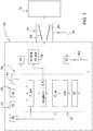
- Fig. 1 shows an arrangement 10 with several components for controlling the working operation of an attachment 12.
- the attachment 12 is coupled to a tractor 16 via a power lift 14.
- the arrangement 10 is at least partially and in particular completely arranged on the tractor side. It has a control unit 18 which contains the sub-units required for signal processing, such as read and / or write unit, memory unit, processor.
- the control unit 18 can have sub-units that are physically separate from one another or can be arranged as a single block on the tractor 16.
- the control unit 18 receives sensor signals from an optical sensor system 20 (eg RGB camera, stereo camera) which is attached to one (or more) suitable position (s) of the tractor 16. These sensor signals can be referred to as image data or raw data RD of a lower link 22 or 24 or of the two lower links 22, 24 of the power lift 14. With the arrow 26 in Fig. 1 it is indicated that the optical sensor system 20 optically detects the location or position of the respective lower link 22, 24.
- an optical sensor system 20 eg RGB camera, stereo camera
- a data processing unit 28 within the control unit 18 determines two reference angles ⁇ and ⁇ to be described below ( Fig. 2 ). From these reference angles ⁇ and ⁇ , the control unit 18 calculates the current position P_ist of a traction point P, which is still to be explained.
- the current position P_ist is preferably determined in the form of coordinates x, y of a defined coordinate system 30 ( Fig. 2 ).
- the determined position P_ist of the towing point P can be signaled to the driver via a display unit 32 of the tractor 16.
- the determined position P_ist of the tension point P can be adjusted automatically depending on the result of a comparison with a target specification.
- the target specification is a target position P_soll of the traction point P.
- the target specification P_soll is compared with the current position P_ist within the framework of an algorithm.
- function signals S_f can be generated in the control unit 18, which control the power lift 14 or its two lower links 22, 24 for their adjustment. This adjustment of the lower links 22, 24 can thus bring about an automatic implementation of a target specification.
- the function signals S_f can be viewed as control signals for triggering a technical function.
- One such function is the adjustment of the lower links 22, 24 to adjust and optimize the position of the traction point P.
- a length L of a variable-length lateral stabilizer 34 which is coupled to one of the two lower links 22, 24, is adjusted.
- Another technical function is the activation of a warning device 36 on the tractor 16, which informs the driver, in particular optically and / or acoustically, when the pull point P should be optimized.
- a further function in the form of an automatic intervention in a steering control unit 38 of the tractor steering can be triggered by means of the function signal S_f.
- the function signal S_f is taken into account, for example, when calculating the steering angle W_lenk of a GPS-controlled steering system or taken into account as an angle change to be added with respect to a desired steering angle W_soll specified by the driver.
- the triggering of the function with respect to the warning device 36 and the steering control unit 38 are each possible as an alternative or in addition to the adjustment of the lower links 22, 24 and are therefore indicated with dashed arrows.
- the target specification P_soll can be specified, for example, by the driver or user via a user interface 40.
- the target specification P_soll can be defined automatically via a tractor-side control device 42 or a bus system 44 of the tractor 16.
- the respective target specification P_soll can optionally be signaled on the display unit 32. The driver or user can then comfortably recognize target specifications and, if necessary, also change them very precisely via the user interface 40.
- a representation of the current position P_ist and the target position P_soll on the display unit 22 is preferably similar to the representation in FIG Fig. 2 so that the user has a good overview of the current position and changes in the train point P.
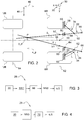
- the coordinate system 30 has an x-axis and a y-axis.
- the x-axis runs parallel to a longitudinal direction 46 of the tractor 16, in particular a vehicle horizontal.
- the y-axis runs parallel to a transverse direction 48 of the tractor 16, in particular a further vehicle horizontal.
- the two axes mentioned intersect at a coordinate origin 50 or zero point, which corresponds to a reference point for the position of the traction point P. As in Fig. 2 recognizable, this reference point corresponds to a center point of a rear axle 52 of the tractor 16.
- FIG. 2 it can be seen that in the work assignment shown there, the position of the pulling point P is located along the longitudinal direction 46 between the rear axle 52 with two rear wheels HR and a front axle 54 with two front wheels VR of the tractor 16.
- the traction point P is the geometric intersection of imaginary extensions of the two lower links 22, 24 ( Fig. 2 ). Based on Fig. 2 explains how the traction point P can be determined with little technical effort as a function of two reference angles ⁇ , ⁇ . An imaginary extension of the respective lower link 22, 24 and one parallel to the Reference straight line 56 running in the longitudinal direction 46, the angle legs of these reference angles ⁇ , ⁇ .
- Each lower link 22, 24 is assigned a side stabilizer 34 of variable length.
- the change in length takes place by means of a corresponding control of a hydraulic cylinder, not shown here.
- the side stabilizer 34 is movably coupled to a support structure 60 of the tractor 16 by a coupling point 58 facing the tractor 16.
- the side stabilizer 34 is articulated to the lower link 22 via an articulation point 62 opposite the coupling point 58.
- This articulation point 62 is located between a coupling point 64 facing the tractor 16 and a coupling point 66 of the lower link 22 facing the attachment 12.
- This design structure also applies analogously to the second lower link 24.
- the distances b1 and b2 starting from the coordinate origin 50 and running along the transverse direction 48, to the imaginary extensions of the lower links 22, 24 can also be calculated.
- the reference angles ⁇ , ⁇ are determined by means of the data processing unit 28. Based on conventional measurements on the power lift 14, such as length measurements on the Lateral stabilizer 34 by means of suitable measuring systems can therefore be dispensed with.
- the image data of the sensor system 20 are fed to a neural network NN1.
- the input signals of the network NN1 thus represent the raw image of a lower link or both lower links 22, 24.
- the output signals of this network NN1 represent a classified binary image of the optically detected lower links 22, 24.
- the lower link pixels are assigned a value, while all other image pixels outside the lower links 22, 24 have a different value.
- the output signals or output data of the network NN1 are compared in a test stage 68 with predefined plausibility data. The output data of the test stage 68 therefore represent a possibly corrected binary image of the lower links 22, 24.
- the values of the reference angles ⁇ and ⁇ are derived in a further neural network NN2.
- a further neural network is provided at the test stage 68 for deriving the second reference angle.
- Fig. 4 shows a further embodiment of the data processing unit 28.
- the optical sensor system 20 sends the image data or the raw image to a neural network NN3.
- This network NN3 preferably has two output neurons with a linear activation function.
- the regression approach used in the network NN3 leads to a value-continuous prediction of the two reference angles ⁇ and ⁇ considered.
- test stage 70 suitable predefined plausibility data are used to test the predicted reference angle values for their plausibility.
- the output data of the test stage 70 represent, if necessary, corrected values of the reference angles ⁇ and ⁇ .
Landscapes
- Engineering & Computer Science (AREA)
- Life Sciences & Earth Sciences (AREA)
- Physics & Mathematics (AREA)
- Theoretical Computer Science (AREA)
- General Physics & Mathematics (AREA)
- Environmental Sciences (AREA)
- Soil Sciences (AREA)
- Mechanical Engineering (AREA)
- Computational Linguistics (AREA)
- Biophysics (AREA)
- General Health & Medical Sciences (AREA)
- Molecular Biology (AREA)
- Computing Systems (AREA)
- General Engineering & Computer Science (AREA)
- Data Mining & Analysis (AREA)
- Mathematical Physics (AREA)
- Software Systems (AREA)
- Evolutionary Computation (AREA)
- Biomedical Technology (AREA)
- Artificial Intelligence (AREA)
- Health & Medical Sciences (AREA)
- Aviation & Aerospace Engineering (AREA)
- Radar, Positioning & Navigation (AREA)
- Remote Sensing (AREA)
- Automation & Control Theory (AREA)
- Computer Vision & Pattern Recognition (AREA)
- Zoology (AREA)
- Guiding Agricultural Machines (AREA)
Applications Claiming Priority (1)
| Application Number | Priority Date | Filing Date | Title |
|---|---|---|---|
| DE102019213746.6A DE102019213746A1 (de) | 2019-09-10 | 2019-09-10 | Verfahren zur Steuerung des Betriebs eines Anbaugerätes |
Publications (2)
| Publication Number | Publication Date |
|---|---|
| EP3791704A1 true EP3791704A1 (fr) | 2021-03-17 |
| EP3791704B1 EP3791704B1 (fr) | 2022-06-15 |
Family
ID=72292295
Family Applications (1)
| Application Number | Title | Priority Date | Filing Date |
|---|---|---|---|
| EP20193515.2A Active EP3791704B1 (fr) | 2019-09-10 | 2020-08-31 | Procédé de commande du fonctionnement d'un outil de travail |
Country Status (3)
| Country | Link |
|---|---|
| US (1) | US11864482B2 (fr) |
| EP (1) | EP3791704B1 (fr) |
| DE (1) | DE102019213746A1 (fr) |
Cited By (1)
| Publication number | Priority date | Publication date | Assignee | Title |
|---|---|---|---|---|
| EP4311409A1 (fr) * | 2022-07-29 | 2024-01-31 | CNH Industrial Sweden AB | Contrôleur pour une charrue, système de charrue et procédés associés |
Families Citing this family (2)
| Publication number | Priority date | Publication date | Assignee | Title |
|---|---|---|---|---|
| EP4193821A1 (fr) * | 2021-12-07 | 2023-06-14 | CNH Industrial Italia S.p.A. | Procédé et appareil de commande d'un attelage d'un véhicule de travail |
| EP4544891B1 (fr) * | 2023-10-27 | 2026-01-21 | Kverneland Group Nieuw-Vennep B.V. | Procédé de commande d'un angle d'inclinaison d'un outil et machine de travail |
Citations (5)
| Publication number | Priority date | Publication date | Assignee | Title |
|---|---|---|---|---|
| DE2845111A1 (de) * | 1978-10-17 | 1980-04-24 | Lemken Kg Pflugfab | Getriebe zur verstellung der breite und des ideellen schlepperzugpunktes eines pfluges |
| EP1252806A2 (fr) * | 2001-04-27 | 2002-10-30 | Deere & Company | Interface entre véhicule de travail et outil ainsi que dispositif de contrôle |
| US9555813B2 (en) | 2012-09-06 | 2017-01-31 | Jaguar Land Rover Limited | Method and system for preventing instability in a vehicle-trailer combination |
| DE102015009889A1 (de) * | 2015-07-29 | 2017-02-02 | Walter Hege | Landwirtschaftliches Zugsystem mit Positionsbestimmungssystem zum Steuern von Anbaugeräten |
| EP3300558A1 (fr) * | 2016-09-29 | 2018-04-04 | Robert Bosch GmbH | Dispositif et procédé de réglage du fonctionnement d'un appareil isolé hydraulique d'un véhicule |
Family Cites Families (1)
| Publication number | Priority date | Publication date | Assignee | Title |
|---|---|---|---|---|
| DE102015224757A1 (de) | 2015-12-10 | 2017-06-14 | Robert Bosch Gmbh | Vorrichtung und Verfahren zur Regelung des Betriebs eines hydraulisch betätigbaren Schleppgeräts an einem Fahrzeug |
-
2019
- 2019-09-10 DE DE102019213746.6A patent/DE102019213746A1/de not_active Withdrawn
-
2020
- 2020-08-05 US US16/985,428 patent/US11864482B2/en active Active
- 2020-08-31 EP EP20193515.2A patent/EP3791704B1/fr active Active
Patent Citations (5)
| Publication number | Priority date | Publication date | Assignee | Title |
|---|---|---|---|---|
| DE2845111A1 (de) * | 1978-10-17 | 1980-04-24 | Lemken Kg Pflugfab | Getriebe zur verstellung der breite und des ideellen schlepperzugpunktes eines pfluges |
| EP1252806A2 (fr) * | 2001-04-27 | 2002-10-30 | Deere & Company | Interface entre véhicule de travail et outil ainsi que dispositif de contrôle |
| US9555813B2 (en) | 2012-09-06 | 2017-01-31 | Jaguar Land Rover Limited | Method and system for preventing instability in a vehicle-trailer combination |
| DE102015009889A1 (de) * | 2015-07-29 | 2017-02-02 | Walter Hege | Landwirtschaftliches Zugsystem mit Positionsbestimmungssystem zum Steuern von Anbaugeräten |
| EP3300558A1 (fr) * | 2016-09-29 | 2018-04-04 | Robert Bosch GmbH | Dispositif et procédé de réglage du fonctionnement d'un appareil isolé hydraulique d'un véhicule |
Cited By (1)
| Publication number | Priority date | Publication date | Assignee | Title |
|---|---|---|---|---|
| EP4311409A1 (fr) * | 2022-07-29 | 2024-01-31 | CNH Industrial Sweden AB | Contrôleur pour une charrue, système de charrue et procédés associés |
Also Published As
| Publication number | Publication date |
|---|---|
| US20210068332A1 (en) | 2021-03-11 |
| EP3791704B1 (fr) | 2022-06-15 |
| US11864482B2 (en) | 2024-01-09 |
| DE102019213746A1 (de) | 2021-03-11 |
Similar Documents
| Publication | Publication Date | Title |
|---|---|---|
| EP3413086B1 (fr) | Procédé de caractérisation d'une remorque attachée à un véhicule tracteur, système d'aide à la conduite ainsi qu'ensemble attelé | |
| EP2987912B1 (fr) | Fraiseuse automobile, et procédé d'évacuation de produit de fraisage | |
| EP3593616A1 (fr) | Engin de travail agricole | |
| DE102019131702A1 (de) | Anhängerwinkelerfassung unter verwendung von ende-zu-ende-lernen | |
| EP3791704B1 (fr) | Procédé de commande du fonctionnement d'un outil de travail | |
| EP3616496A1 (fr) | Engin de travail agricole | |
| DE102016209896A1 (de) | Verfahren zur Längenschätzung von Anhängern unter Verwendung eines Anhängergierratensignals | |
| EP3640676B1 (fr) | Procédé de surveillance d'un environnement d'un attelage d'un véhicule tracteur et d'une remorque tractée par le véhicule tracteur ainsi qu'appareil de commande pour le véhicule tracteur et véhicule tracteur doté de l'appareil de commande | |
| EP3342264B1 (fr) | Dispositif et procédé de réglage du fonctionnement d'un véhicule avec un outil porté ou une remorque | |
| EP3284649A1 (fr) | Assistance au conducteur pour la mise en stationnement d'un véhicule automobile comprenant une remorque attelée à partir de capteurs virtuels | |
| DE102014218995A1 (de) | Verfahren und Vorrichtung zur Bird-View-Darstellung eines Fahrzeuggespanns sowie nachrüstbare Kamera | |
| WO2020052886A1 (fr) | Procédé de direction transversale et dispositif de direction transversale pour le déplacement d'un véhicule dans une position cible, et véhicule approprié | |
| EP3400766A1 (fr) | Procédé et dispositif de détermination d'une inclinaison d'un appareil rapporté inclinable d'un véhicule | |
| EP3165090B1 (fr) | Système de commande et/ou de réglage d'une machine agricole | |
| EP3769599A1 (fr) | Procédé de détection d'un obstacle | |
| EP3476696B1 (fr) | Procédé de détermination des limites d'un objet dans une zone externe d'un véhicule automobile ainsi que dispositif de commande et véhicule automobile | |
| EP2353970B1 (fr) | Guidage forcé | |
| DE102017119317A1 (de) | Klassifizierung von Umgebungs-Fahrzeugen für eine Abstandsregeltempomat-Vorrichtung in einem Kraftfahrzeug | |
| EP3721691A1 (fr) | Procédé de commande du fonctionnement d'un accessoire | |
| DE102021116289B4 (de) | Landwirtschaftliches Gerät und Verfahren zur Lenkung des landwirtschaftlichen Geräts | |
| EP2218629B1 (fr) | Véhicule doté d'une barre de connexion variable en longueur | |
| DE102015002715B4 (de) | Verfahren und System zum Feststellen des Funktionsstatus bei einer Spoilervorrichtung eines Fahrzeugs | |
| DE102020213302B4 (de) | Fahrzeugverfolgungseinrichtung | |
| DE102014113070A1 (de) | Justiervorrichtung und Verfahren zum Ausrichten eines Bauteils an einem Fahrzeug | |
| DE102019110018B4 (de) | Verfahren zur Kollisionsvermeidung, System, fahrzeuginternes System, Zugfahrzeug und Signal |
Legal Events
| Date | Code | Title | Description |
|---|---|---|---|
| PUAI | Public reference made under article 153(3) epc to a published international application that has entered the european phase |
Free format text: ORIGINAL CODE: 0009012 |
|
| STAA | Information on the status of an ep patent application or granted ep patent |
Free format text: STATUS: THE APPLICATION HAS BEEN PUBLISHED |
|
| AK | Designated contracting states |
Kind code of ref document: A1 Designated state(s): AL AT BE BG CH CY CZ DE DK EE ES FI FR GB GR HR HU IE IS IT LI LT LU LV MC MK MT NL NO PL PT RO RS SE SI SK SM TR |
|
| AX | Request for extension of the european patent |
Extension state: BA ME |
|
| STAA | Information on the status of an ep patent application or granted ep patent |
Free format text: STATUS: REQUEST FOR EXAMINATION WAS MADE |
|
| 17P | Request for examination filed |
Effective date: 20210917 |
|
| RBV | Designated contracting states (corrected) |
Designated state(s): AL AT BE BG CH CY CZ DE DK EE ES FI FR GB GR HR HU IE IS IT LI LT LU LV MC MK MT NL NO PL PT RO RS SE SI SK SM TR |
|
| GRAP | Despatch of communication of intention to grant a patent |
Free format text: ORIGINAL CODE: EPIDOSNIGR1 |
|
| STAA | Information on the status of an ep patent application or granted ep patent |
Free format text: STATUS: GRANT OF PATENT IS INTENDED |
|
| INTG | Intention to grant announced |
Effective date: 20220204 |
|
| GRAS | Grant fee paid |
Free format text: ORIGINAL CODE: EPIDOSNIGR3 |
|
| GRAA | (expected) grant |
Free format text: ORIGINAL CODE: 0009210 |
|
| STAA | Information on the status of an ep patent application or granted ep patent |
Free format text: STATUS: THE PATENT HAS BEEN GRANTED |
|
| AK | Designated contracting states |
Kind code of ref document: B1 Designated state(s): AL AT BE BG CH CY CZ DE DK EE ES FI FR GB GR HR HU IE IS IT LI LT LU LV MC MK MT NL NO PL PT RO RS SE SI SK SM TR |
|
| REG | Reference to a national code |
Ref country code: CH Ref legal event code: EP Ref country code: GB Ref legal event code: FG4D Free format text: NOT ENGLISH |
|
| REG | Reference to a national code |
Ref country code: IE Ref legal event code: FG4D Free format text: LANGUAGE OF EP DOCUMENT: GERMAN |
|
| REG | Reference to a national code |
Ref country code: DE Ref legal event code: R096 Ref document number: 502020001237 Country of ref document: DE |
|
| REG | Reference to a national code |
Ref country code: AT Ref legal event code: REF Ref document number: 1497811 Country of ref document: AT Kind code of ref document: T Effective date: 20220715 |
|
| REG | Reference to a national code |
Ref country code: LT Ref legal event code: MG9D |
|
| REG | Reference to a national code |
Ref country code: NL Ref legal event code: MP Effective date: 20220615 |
|
| PG25 | Lapsed in a contracting state [announced via postgrant information from national office to epo] |
Ref country code: SE Free format text: LAPSE BECAUSE OF FAILURE TO SUBMIT A TRANSLATION OF THE DESCRIPTION OR TO PAY THE FEE WITHIN THE PRESCRIBED TIME-LIMIT Effective date: 20220615 Ref country code: NO Free format text: LAPSE BECAUSE OF FAILURE TO SUBMIT A TRANSLATION OF THE DESCRIPTION OR TO PAY THE FEE WITHIN THE PRESCRIBED TIME-LIMIT Effective date: 20220915 Ref country code: LT Free format text: LAPSE BECAUSE OF FAILURE TO SUBMIT A TRANSLATION OF THE DESCRIPTION OR TO PAY THE FEE WITHIN THE PRESCRIBED TIME-LIMIT Effective date: 20220615 Ref country code: HR Free format text: LAPSE BECAUSE OF FAILURE TO SUBMIT A TRANSLATION OF THE DESCRIPTION OR TO PAY THE FEE WITHIN THE PRESCRIBED TIME-LIMIT Effective date: 20220615 Ref country code: GR Free format text: LAPSE BECAUSE OF FAILURE TO SUBMIT A TRANSLATION OF THE DESCRIPTION OR TO PAY THE FEE WITHIN THE PRESCRIBED TIME-LIMIT Effective date: 20220916 Ref country code: FI Free format text: LAPSE BECAUSE OF FAILURE TO SUBMIT A TRANSLATION OF THE DESCRIPTION OR TO PAY THE FEE WITHIN THE PRESCRIBED TIME-LIMIT Effective date: 20220615 Ref country code: BG Free format text: LAPSE BECAUSE OF FAILURE TO SUBMIT A TRANSLATION OF THE DESCRIPTION OR TO PAY THE FEE WITHIN THE PRESCRIBED TIME-LIMIT Effective date: 20220915 |
|
| PG25 | Lapsed in a contracting state [announced via postgrant information from national office to epo] |
Ref country code: RS Free format text: LAPSE BECAUSE OF FAILURE TO SUBMIT A TRANSLATION OF THE DESCRIPTION OR TO PAY THE FEE WITHIN THE PRESCRIBED TIME-LIMIT Effective date: 20220615 Ref country code: LV Free format text: LAPSE BECAUSE OF FAILURE TO SUBMIT A TRANSLATION OF THE DESCRIPTION OR TO PAY THE FEE WITHIN THE PRESCRIBED TIME-LIMIT Effective date: 20220615 |
|
| PG25 | Lapsed in a contracting state [announced via postgrant information from national office to epo] |
Ref country code: NL Free format text: LAPSE BECAUSE OF FAILURE TO SUBMIT A TRANSLATION OF THE DESCRIPTION OR TO PAY THE FEE WITHIN THE PRESCRIBED TIME-LIMIT Effective date: 20220615 |
|
| PG25 | Lapsed in a contracting state [announced via postgrant information from national office to epo] |
Ref country code: SM Free format text: LAPSE BECAUSE OF FAILURE TO SUBMIT A TRANSLATION OF THE DESCRIPTION OR TO PAY THE FEE WITHIN THE PRESCRIBED TIME-LIMIT Effective date: 20220615 Ref country code: SK Free format text: LAPSE BECAUSE OF FAILURE TO SUBMIT A TRANSLATION OF THE DESCRIPTION OR TO PAY THE FEE WITHIN THE PRESCRIBED TIME-LIMIT Effective date: 20220615 Ref country code: RO Free format text: LAPSE BECAUSE OF FAILURE TO SUBMIT A TRANSLATION OF THE DESCRIPTION OR TO PAY THE FEE WITHIN THE PRESCRIBED TIME-LIMIT Effective date: 20220615 Ref country code: PT Free format text: LAPSE BECAUSE OF FAILURE TO SUBMIT A TRANSLATION OF THE DESCRIPTION OR TO PAY THE FEE WITHIN THE PRESCRIBED TIME-LIMIT Effective date: 20221017 Ref country code: ES Free format text: LAPSE BECAUSE OF FAILURE TO SUBMIT A TRANSLATION OF THE DESCRIPTION OR TO PAY THE FEE WITHIN THE PRESCRIBED TIME-LIMIT Effective date: 20220615 Ref country code: EE Free format text: LAPSE BECAUSE OF FAILURE TO SUBMIT A TRANSLATION OF THE DESCRIPTION OR TO PAY THE FEE WITHIN THE PRESCRIBED TIME-LIMIT Effective date: 20220615 Ref country code: CZ Free format text: LAPSE BECAUSE OF FAILURE TO SUBMIT A TRANSLATION OF THE DESCRIPTION OR TO PAY THE FEE WITHIN THE PRESCRIBED TIME-LIMIT Effective date: 20220615 |
|
| PG25 | Lapsed in a contracting state [announced via postgrant information from national office to epo] |
Ref country code: PL Free format text: LAPSE BECAUSE OF FAILURE TO SUBMIT A TRANSLATION OF THE DESCRIPTION OR TO PAY THE FEE WITHIN THE PRESCRIBED TIME-LIMIT Effective date: 20220615 Ref country code: IS Free format text: LAPSE BECAUSE OF FAILURE TO SUBMIT A TRANSLATION OF THE DESCRIPTION OR TO PAY THE FEE WITHIN THE PRESCRIBED TIME-LIMIT Effective date: 20221015 |
|
| REG | Reference to a national code |
Ref country code: DE Ref legal event code: R097 Ref document number: 502020001237 Country of ref document: DE |
|
| PG25 | Lapsed in a contracting state [announced via postgrant information from national office to epo] |
Ref country code: MC Free format text: LAPSE BECAUSE OF FAILURE TO SUBMIT A TRANSLATION OF THE DESCRIPTION OR TO PAY THE FEE WITHIN THE PRESCRIBED TIME-LIMIT Effective date: 20220615 Ref country code: AL Free format text: LAPSE BECAUSE OF FAILURE TO SUBMIT A TRANSLATION OF THE DESCRIPTION OR TO PAY THE FEE WITHIN THE PRESCRIBED TIME-LIMIT Effective date: 20220615 |
|
| PLBE | No opposition filed within time limit |
Free format text: ORIGINAL CODE: 0009261 |
|
| STAA | Information on the status of an ep patent application or granted ep patent |
Free format text: STATUS: NO OPPOSITION FILED WITHIN TIME LIMIT |
|
| PG25 | Lapsed in a contracting state [announced via postgrant information from national office to epo] |
Ref country code: LU Free format text: LAPSE BECAUSE OF NON-PAYMENT OF DUE FEES Effective date: 20220831 Ref country code: DK Free format text: LAPSE BECAUSE OF FAILURE TO SUBMIT A TRANSLATION OF THE DESCRIPTION OR TO PAY THE FEE WITHIN THE PRESCRIBED TIME-LIMIT Effective date: 20220615 |
|
| REG | Reference to a national code |
Ref country code: BE Ref legal event code: MM Effective date: 20220831 |
|
| 26N | No opposition filed |
Effective date: 20230316 |
|
| PG25 | Lapsed in a contracting state [announced via postgrant information from national office to epo] |
Ref country code: SI Free format text: LAPSE BECAUSE OF FAILURE TO SUBMIT A TRANSLATION OF THE DESCRIPTION OR TO PAY THE FEE WITHIN THE PRESCRIBED TIME-LIMIT Effective date: 20220615 |
|
| PG25 | Lapsed in a contracting state [announced via postgrant information from national office to epo] |
Ref country code: IE Free format text: LAPSE BECAUSE OF NON-PAYMENT OF DUE FEES Effective date: 20220831 |
|
| PG25 | Lapsed in a contracting state [announced via postgrant information from national office to epo] |
Ref country code: BE Free format text: LAPSE BECAUSE OF NON-PAYMENT OF DUE FEES Effective date: 20220831 |
|
| PG25 | Lapsed in a contracting state [announced via postgrant information from national office to epo] |
Ref country code: IT Free format text: LAPSE BECAUSE OF FAILURE TO SUBMIT A TRANSLATION OF THE DESCRIPTION OR TO PAY THE FEE WITHIN THE PRESCRIBED TIME-LIMIT Effective date: 20220615 |
|
| REG | Reference to a national code |
Ref country code: CH Ref legal event code: PL |
|
| PG25 | Lapsed in a contracting state [announced via postgrant information from national office to epo] |
Ref country code: CY Free format text: LAPSE BECAUSE OF FAILURE TO SUBMIT A TRANSLATION OF THE DESCRIPTION OR TO PAY THE FEE WITHIN THE PRESCRIBED TIME-LIMIT Effective date: 20220615 Ref country code: CH Free format text: LAPSE BECAUSE OF NON-PAYMENT OF DUE FEES Effective date: 20230831 |
|
| PG25 | Lapsed in a contracting state [announced via postgrant information from national office to epo] |
Ref country code: MK Free format text: LAPSE BECAUSE OF FAILURE TO SUBMIT A TRANSLATION OF THE DESCRIPTION OR TO PAY THE FEE WITHIN THE PRESCRIBED TIME-LIMIT Effective date: 20220615 Ref country code: HU Free format text: LAPSE BECAUSE OF FAILURE TO SUBMIT A TRANSLATION OF THE DESCRIPTION OR TO PAY THE FEE WITHIN THE PRESCRIBED TIME-LIMIT; INVALID AB INITIO Effective date: 20200831 |
|
| PG25 | Lapsed in a contracting state [announced via postgrant information from national office to epo] |
Ref country code: MT Free format text: LAPSE BECAUSE OF FAILURE TO SUBMIT A TRANSLATION OF THE DESCRIPTION OR TO PAY THE FEE WITHIN THE PRESCRIBED TIME-LIMIT Effective date: 20220615 |
|
| PG25 | Lapsed in a contracting state [announced via postgrant information from national office to epo] |
Ref country code: BG Free format text: LAPSE BECAUSE OF FAILURE TO SUBMIT A TRANSLATION OF THE DESCRIPTION OR TO PAY THE FEE WITHIN THE PRESCRIBED TIME-LIMIT Effective date: 20220615 |
|
| PG25 | Lapsed in a contracting state [announced via postgrant information from national office to epo] |
Ref country code: BG Free format text: LAPSE BECAUSE OF FAILURE TO SUBMIT A TRANSLATION OF THE DESCRIPTION OR TO PAY THE FEE WITHIN THE PRESCRIBED TIME-LIMIT Effective date: 20220615 |
|
| GBPC | Gb: european patent ceased through non-payment of renewal fee |
Effective date: 20240831 |
|
| PG25 | Lapsed in a contracting state [announced via postgrant information from national office to epo] |
Ref country code: GB Free format text: LAPSE BECAUSE OF NON-PAYMENT OF DUE FEES Effective date: 20240831 |
|
| PGFP | Annual fee paid to national office [announced via postgrant information from national office to epo] |
Ref country code: DE Payment date: 20250721 Year of fee payment: 6 |
|
| PGFP | Annual fee paid to national office [announced via postgrant information from national office to epo] |
Ref country code: AT Payment date: 20251020 Year of fee payment: 5 Ref country code: FR Payment date: 20250825 Year of fee payment: 6 |
|
| PG25 | Lapsed in a contracting state [announced via postgrant information from national office to epo] |
Ref country code: TR Free format text: LAPSE BECAUSE OF FAILURE TO SUBMIT A TRANSLATION OF THE DESCRIPTION OR TO PAY THE FEE WITHIN THE PRESCRIBED TIME-LIMIT Effective date: 20220615 |