EP3616771B1 - Module à air comprimé pour un véhicule utilitaire et son procédé d'essai - Google Patents
Module à air comprimé pour un véhicule utilitaire et son procédé d'essai Download PDFInfo
- Publication number
- EP3616771B1 EP3616771B1 EP19192987.6A EP19192987A EP3616771B1 EP 3616771 B1 EP3616771 B1 EP 3616771B1 EP 19192987 A EP19192987 A EP 19192987A EP 3616771 B1 EP3616771 B1 EP 3616771B1
- Authority
- EP
- European Patent Office
- Prior art keywords
- air
- compressed air
- compressed
- module
- valve unit
- Prior art date
- Legal status (The legal status is an assumption and is not a legal conclusion. Google has not performed a legal analysis and makes no representation as to the accuracy of the status listed.)
- Active
Links
Images
Classifications
-
- B—PERFORMING OPERATIONS; TRANSPORTING
- B60—VEHICLES IN GENERAL
- B60T—VEHICLE BRAKE CONTROL SYSTEMS OR PARTS THEREOF; BRAKE CONTROL SYSTEMS OR PARTS THEREOF, IN GENERAL; ARRANGEMENT OF BRAKING ELEMENTS ON VEHICLES IN GENERAL; PORTABLE DEVICES FOR PREVENTING UNWANTED MOVEMENT OF VEHICLES; VEHICLE MODIFICATIONS TO FACILITATE COOLING OF BRAKES
- B60T17/00—Component parts, details, or accessories of power brake systems not covered by groups B60T8/00, B60T13/00 or B60T15/00, or presenting other characteristic features
- B60T17/002—Air treatment devices
- B60T17/004—Draining and drying devices
-
- B—PERFORMING OPERATIONS; TRANSPORTING
- B60—VEHICLES IN GENERAL
- B60T—VEHICLE BRAKE CONTROL SYSTEMS OR PARTS THEREOF; BRAKE CONTROL SYSTEMS OR PARTS THEREOF, IN GENERAL; ARRANGEMENT OF BRAKING ELEMENTS ON VEHICLES IN GENERAL; PORTABLE DEVICES FOR PREVENTING UNWANTED MOVEMENT OF VEHICLES; VEHICLE MODIFICATIONS TO FACILITATE COOLING OF BRAKES
- B60T17/00—Component parts, details, or accessories of power brake systems not covered by groups B60T8/00, B60T13/00 or B60T15/00, or presenting other characteristic features
- B60T17/002—Air treatment devices
-
- B—PERFORMING OPERATIONS; TRANSPORTING
- B60—VEHICLES IN GENERAL
- B60T—VEHICLE BRAKE CONTROL SYSTEMS OR PARTS THEREOF; BRAKE CONTROL SYSTEMS OR PARTS THEREOF, IN GENERAL; ARRANGEMENT OF BRAKING ELEMENTS ON VEHICLES IN GENERAL; PORTABLE DEVICES FOR PREVENTING UNWANTED MOVEMENT OF VEHICLES; VEHICLE MODIFICATIONS TO FACILITATE COOLING OF BRAKES
- B60T17/00—Component parts, details, or accessories of power brake systems not covered by groups B60T8/00, B60T13/00 or B60T15/00, or presenting other characteristic features
- B60T17/02—Arrangements of pumps or compressors, or control devices therefor
-
- F—MECHANICAL ENGINEERING; LIGHTING; HEATING; WEAPONS; BLASTING
- F04—POSITIVE - DISPLACEMENT MACHINES FOR LIQUIDS; PUMPS FOR LIQUIDS OR ELASTIC FLUIDS
- F04B—POSITIVE-DISPLACEMENT MACHINES FOR LIQUIDS; PUMPS
- F04B41/00—Pumping installations or systems specially adapted for elastic fluids
- F04B41/02—Pumping installations or systems specially adapted for elastic fluids having reservoirs
-
- F—MECHANICAL ENGINEERING; LIGHTING; HEATING; WEAPONS; BLASTING
- F15—FLUID-PRESSURE ACTUATORS; HYDRAULICS OR PNEUMATICS IN GENERAL
- F15B—SYSTEMS ACTING BY MEANS OF FLUIDS IN GENERAL; FLUID-PRESSURE ACTUATORS, e.g. SERVOMOTORS; DETAILS OF FLUID-PRESSURE SYSTEMS, NOT OTHERWISE PROVIDED FOR
- F15B21/00—Common features of fluid actuator systems; Fluid-pressure actuator systems or details thereof, not covered by any other group of this subclass
- F15B21/04—Special measures taken in connection with the properties of the fluid
- F15B21/048—Arrangements for compressed air preparation, e.g. comprising air driers, air condensers, filters, lubricators or pressure regulators
-
- F—MECHANICAL ENGINEERING; LIGHTING; HEATING; WEAPONS; BLASTING
- F04—POSITIVE - DISPLACEMENT MACHINES FOR LIQUIDS; PUMPS FOR LIQUIDS OR ELASTIC FLUIDS
- F04B—POSITIVE-DISPLACEMENT MACHINES FOR LIQUIDS; PUMPS
- F04B39/00—Component parts, details, or accessories, of pumps or pumping systems specially adapted for elastic fluids, not otherwise provided for in, or of interest apart from, groups F04B25/00 - F04B37/00
- F04B39/16—Filtration; Moisture separation
Definitions
- the invention relates to a compressed air module for mounting on a frame of a commercial vehicle and a method for testing the function of the compressed air module.
- the U.S. 2007/0234904 A1 discloses a dry compressed air module for attachment to the frame of a commercial vehicle.
- the dry compressed air module consists of a housing, an air compressor, an air dryer and a reservoir.
- the air compressor, the air dryer and the reservoir are arranged in a housing and can be attached to the frame together with the housing.
- the air dryer is supplied with compressed air from the air compressor and the reservoir with dry compressed air from the air dryer.
- the container is able to store the dry compressed air and supply it to the commercial vehicle.
- the DE 10 2012 005308 A1 discloses a compressed air supply system for operating an air spring system of a passenger car, having an air dryer arrangement, an air compressor, a motor, a valve arrangement for controlling a compressed air flow, and a housing.
- the object of the invention is to provide an alternative and/or improved compressed air module.
- the invention creates a compressed air module for mounting on a frame of a commercial vehicle.
- the compressed air module has an air compressor for compressing air, a compressed air reservoir for storing compressed air and a compressed air treatment for cleaning, dehumidifying and/or cooling compressed air.
- the compressed air module has at least one compressed air brake valve unit, which is preferably assigned to a compressed air brake system of the commercial vehicle.
- the compressed air module has a holding device which is designed for mounting on the frame and carries the air compressor, the compressed air reservoir, the compressed air preparation and/or the at least one compressed air brake valve unit (eg directly).
- the compressed air module offers the advantage that all components required for a braking function (apart from the brake cylinders on the respective axles) are integrated in one module.
- the compressed air module can be pre-assembled and checked for functionality. Expedient the compressed air module can be pre-assembled independently and testable with an external power supply. After a successful function test, the compressed air module can be mounted on the frame of the commercial vehicle.
- the compressed air module can also be modularly expandable to vehicle-specific additional compressed air components to implement additional pneumatic functions of the commercial vehicle.
- the compressed air module can be used particularly expediently when assembling a fully or partially electrified commercial vehicle (e.g. electric commercial vehicle or hybrid commercial vehicle).
- a fully or partially electrified commercial vehicle e.g. electric commercial vehicle or hybrid commercial vehicle.
- the arrangement and installation of the components for compressed air generation and processing and their functional connections could in principle be arranged according to free installation spaces.
- the free installation space for the compressed air components can be very limited.
- the compact compressed air module according to the present disclosure with its large number of mechanical, electrical and pneumatic compressed air components can be particularly advantageous.
- the compressed air treatment can be arranged in pneumatic fluid communication downstream of the air compressor. It is possible for the compressed air reservoir to be arranged in pneumatic fluid communication downstream of the compressed air preparation. It is also possible that the at least one compressed air brake valve unit is arranged in pneumatic fluid communication downstream of the compressed air reservoir.
- the at least one compressed air brake valve unit has a compressed air service brake valve unit, which is preferably assigned to an electronically controlled compressed air service brake system (e.g., comprising an antilock braking system and/or a traction control system) of the commercial vehicle.
- the at least one compressed air brake valve unit has a compressed air parking brake valve unit, which is preferably assigned to an electric compressed air parking brake system, preferably of the utility vehicle.
- the compressed air service brake valve unit is designed to control brake pressures on a front axle of the utility vehicle and/or a rear axle of the utility vehicle.
- the compressed air service brake valve unit has a proportional valve, which is preferably assigned to a front axle of the commercial vehicle, and/or a rear axle modulator, which is preferably assigned to a rear axle of the commercial vehicle.
- the compressed air parking brake valve unit is designed to control a parking brake on an axle of the utility vehicle.
- the compressed air module has a compressed air air suspension valve unit, which is preferably assigned to an electronically controlled air suspension system, preferably of the commercial vehicle, and is carried on the holding device. A range of functions of the compressed air module can thus be extended to control an air suspension system.
- the compressed air air suspension valve unit is designed to build up, maintain and/or reduce a pressure in an electronically controlled air suspension system.
- the compressed air air suspension valve unit has a front axle valve for an air-sprung front axle of the commercial vehicle, a rear axle valve for an air-sprung rear axle of the commercial vehicle and/or a rear-axle lift axle valve for an air-sprung lift rear axle of the commercial vehicle.
- the compressed air device also has a regeneration device for regenerating the compressed air treatment.
- the regeneration device is at least partially carried on the holding device.
- the regeneration device can expediently be arranged in a pneumatic fluid connection with the compressed air preparation.
- the holding device is designed at least in sections as a sealed hollow profile and a compressed air regeneration tank of the regeneration device is formed by the sealed hollow profile.
- the compressed air module can expediently have at least one further compressed air valve unit (e.g. compressed air pressure regulator valve unit), which is preferably designed as a solenoid valve unit and/or is carried on the holding device.
- at least one further compressed air valve unit e.g. compressed air pressure regulator valve unit
- the compressed air module is preassembled to enable an independent (e.g. electrical and/or pneumatic) functional test.
- the air compressor, the compressed air reservoir, the compressed air preparation and the at least one compressed air brake valve unit can be preassembled to enable an independent (e.g. electrical and/or pneumatic) functional test in the compressed air module.
- compressed air/air suspension valve unit and/or the regeneration device can also be expediently preassembled in the compressed air module to enable an independent (e.g. electrical and/or pneumatic) functional test.
- the compressed air module is electrically wired so that it can be tested independently.
- the air compressor, the compressed air preparation, the compressed air air suspension valve unit, the regeneration device and/or the at least one compressed air brake valve unit is or are electrically wired in the compressed air module so that it can be tested independently.
- the compressed air module has at least one electrical or electronic interface for independent testing of the electrical and/or electronic functionality of the compressed air module.
- the compressed air module has at least one electrical or electronic interface for independent testing of the electrical and/or electronic functionality of the air compressor, the compressed air preparation, the compressed air air suspension valve unit, the regeneration device and/or the at least one compressed air brake valve unit.
- the compressed air module is pneumatically piped so that it can be tested independently.
- the air compressor, the compressed air reservoir, the compressed air preparation, the compressed air air suspension valve unit, the regeneration device and/or the at least one compressed air brake valve unit is or are independently testable in the compressed air module.
- the compressed air module has at least one pneumatic interface (e.g. test and/or filling connection) for independent testing of the pneumatic functionality of the compressed air module.
- this Compressed air module at least one pneumatic interface for independent testing of the pneumatic functionality of the air compressor, the compressed air treatment, the compressed air air suspension valve unit, the regeneration device and / or the at least one compressed air brake valve unit.
- the at least one pneumatic interface can expediently be arranged in fluid connection downstream of the air compressor, the compressed air preparation, the compressed air air suspension valve unit, the regeneration device and/or the at least one compressed air brake valve unit.
- the holding device can expediently have a plurality of predetermined attachment areas which are designed for selectively modularly receiving or omitting compressed air components comprising the air compressor, the compressed air reservoir, the compressed air preparation and the at least one compressed air brake valve unit.
- the compressed air module is designed to accommodate at least one further compressed air component, preferably a plurality of further compressed air components, optionally in a modular manner.
- the compressed air module has a basic design that can be modularly expanded to include further compressed air components.
- the holding device has at least one (further) predetermined attachment area which is designed to selectively accommodate at least one further compressed air component for the modular expansion of the compressed air module.
- the at least one further compressed air component has a compressed air trailer brake control valve unit and/or a further compressed air reservoir, which is or are preferably assigned to a compressed air trailer brake system (e.g. service brake and/or parking brake).
- the at least one further compressed air component has a compressed air brake valve unit and/or a further compressed air reservoir, which is preferably assigned to a leading or trailing axle of the commercial vehicle.
- the compressed air module can expediently also have a compressed air trailer brake control valve unit and/or a further compressed air reservoir, which is preferably assigned to a compressed air trailer brake system (eg service brake and/or parking brake).
- a compressed air trailer brake system eg service brake and/or parking brake.
- the compressed air module can be a compressed air brake valve unit and/or a further compressed air reservoir, which is preferably assigned to a leading or trailing axle of the commercial vehicle.
- the holding device is designed as an open frame. In this way, individual compressed air components can be modularly supplemented on the holding device in a particularly simple manner.
- the compressed air reservoir is attached to the holding device on the outside.
- the compressed air reservoir is on the outside of the holding device on one side of the holding device that is designed for mounting on the frame; appropriate. This can be advantageous in particular for reasons of space.
- the air compressor, the compressed air preparation and/or the compressed air service brake valve unit is fitted on the inside of the holding device.
- the pneumatic air suspension valve assembly and/or the pneumatic parking brake valve assembly is mounted externally to the fixture and/or above the air compressor.
- the air compressor is driven electrically, preferably externally of the compressed air module by a battery of the utility vehicle.
- the at least one compressed air brake valve unit and/or the compressed air/air suspension valve unit is electrically actuated and/or designed as a solenoid valve unit.
- the compressed air treatment has a particle filter, an air cooler and/or an air dehumidifier.
- the invention also relates to a utility vehicle, preferably a truck or a bus, with a compressed air module as disclosed herein, preferably mounted fixed to the frame of the utility vehicle, preferably adjacent to a rear axle of the utility vehicle.
- the invention also relates to a method for testing the function of a compressed air module as disclosed herein.
- the method includes preassembling the compressed air module to form a unit that can be tested independently, preferably electrically or pneumatically.
- the procedure shows functional, preferably electrical or pneumatic, testing of the pre-assembled compressed air module prior to assembly on the frame of the commercial vehicle.
- the preassembly of the compressed air module can expediently include attachment of the air compressor, the compressed air reservoir, the compressed air treatment, the at least one compressed air brake valve unit, the compressed air air suspension valve unit and/or the regeneration device to the holding device.
- the pre-assembly of the compressed air module includes electrical cabling and/or pneumatic piping of the compressed air module.
- the pre-assembly of the compressed air module includes electrical wiring and/or pneumatic tubing of the air compressor, the compressed air reservoir, the compressed air treatment, the at least one compressed air brake valve unit, the compressed air air suspension valve unit and/or the regeneration device.
- the method can also include mounting the compressed air module on the frame of the commercial vehicle after a positive functional test.
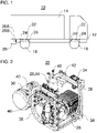
- the figure 1 shows a commercial vehicle 10 purely schematically.
- the commercial vehicle 10 is designed as a truck with a body 14 by way of example. However, it is also possible for the commercial vehicle 10 to be in the form of a bus, for example.
- the utility vehicle 10 can also be included in a utility vehicle combination, for example in a tractor-trailer combination with a tractor-trailer vehicle and semi-trailer or in a trailer combination with a tractor-trailer vehicle and trailer.
- the commercial vehicle 10 can be fully or partially electrified, for example.
- the example utility vehicle 10 includes a frame 12 , such as a ladder frame, the body 14 mounted on the frame 12 , a front axle 16 , and a rear axle 18 .
- the utility vehicle 10 has a compressed air module 20 .
- the compressed air module 20 is attached to the frame 12 .
- the compressed air module 20 is fastened to the outside of the frame 12 behind the rear axle 18, for example in order to keep the line lengths as short as possible.
- the compressed air module 20 preferably serves to mechanically and functionally combine all of the components necessary for a braking function of the utility vehicle 10 .
- the compressed air module 20 can have further compressed air components, for example for an air suspension system of the commercial vehicle 10 or for a compressed air brake system of a trailer of the commercial vehicle 10.
- the further compressed air components can preferably be integrated in a modular manner into the compressed air module 20, each vehicle-specifically with regard to the respective commercial vehicle 10 .
- the compressed air module 20 has one or more, preferably standardized, electrical and/or electronic interfaces 20A.
- control signals for components of the compressed air module 20 can be received via the interface 20A.
- Electrical energy can also be supplied for components of the compressed air module 20 via the interface 20A.
- the compressed air module 20 has one or more, preferably standardized, pneumatic interfaces 20B for delivering compressed air.
- Each system e.g. compressed air brake system, air suspension system, trailer brake system, etc.
- Each system e.g. compressed air brake system, air suspension system, trailer brake system, etc.
- Each system e.g. compressed air brake system, air suspension system, trailer brake system, etc.
- Each system e.g. compressed air brake system, air suspension system, trailer brake system, etc.
- the commercial vehicle 10 also has a compressed air brake system 22 for an electronically controlled service brake and an electric parking brake.
- the electronically controlled service brake can, for example, have an anti-lock braking system and/or a traction control system.
- the air brake system 22 has brake cylinders, e.g. B. for each axis 16 and 18, as in figure 1 shown.
- the air brake system 22 is also partially integrated within the air module 20 in the form of an air service brake valve assembly and an air parking brake valve assembly, as with reference to FIG Figures 2 to 4 is explained in more detail.
- a separate pneumatic interface 20B may each be disposed in fluid communication downstream of the service brake valve assembly and the parking brake valve assembly.
- the utility vehicle 10 can also have an electronically controlled air suspension system 24 .
- the air suspension system 24 can air bags z. B. for one or more of the axes 16 and 18, as in figure 1 is shown.
- the air suspension system 24 may also be partially integrated with the pneumatic module 20 in the form of a pneumatic air suspension valve assembly, as with reference to FIG Figures 2 to 4 is explained in more detail.
- a separate pneumatic interface 20B can be arranged downstream of the compressed air/air suspension valve unit.
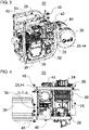
- FIGS. 2 to 4 show an exemplary embodiment variant of the compressed air module 20, which follows with the inclusion of figure 1 is described. For reasons of clarity are in the Figures 2 to 4 electrical wiring and pneumatic tubing within compressed air module 20 are not shown.
- the compressed air module 20 has an air compressor 26 , a compressed air treatment unit 28 , a compressed air reservoir 30 , a compressed air service brake valve unit 32 , a compressed air parking brake valve unit 34 and a holding device 36 .
- the air compressor (also called an air compressor) 26 is designed to compress ambient air into compressed air, for example to a pressure level between 8 bar and 12 bar.
- the air compressor 26 is preferably electrically powered.
- An electrical energy supply for the air compressor 26 can be arranged outside of the compressed air module 20, for example in the form of a vehicle battery or traction battery of the commercial vehicle 10.
- the compressed air preparation 28 is designed to prepare the compressed air for the downstream compressed air systems.
- the compressed air treatment 28 can preferably be a particle filter for removing dirt from the compressed air, an air cooler for cooling the compressed air and/or an air dehumidifier for dehumidifying the compressed air.
- the compressed air treatment 28 is arranged downstream of the air compressor 26 . It is possible for a compressed air pressure regulator valve unit, for example, to be arranged in a fluid connection between the air compressor 26 and the compressed air preparation unit 28 and included in the compressed air module 20 .
- the compressed air processed by the compressed air treatment 28 can be stored in the compressed air reservoir 30 .
- the compressed air treatment 28 is arranged downstream of the air compressor 26 and the compressed air treatment 28 .
- the compressed air service brake valve unit 32 (see figure 3 ) is part of the compressed air brake system 22 of the commercial vehicle 10.
- the compressed air service brake valve unit 32 is designed to control brake pressures of the front axle 16 and the rear axle 18.
- the compressed air service brake valve unit 32 can supply the brake cylinder of the compressed air brake system 22 with compressed air.
- the air service brake valve assembly 32 may include a proportional valve disposed in fluid communication upstream of the brake cylinder in the front axle 16 .
- the air service brake valve assembly 32 may include a rear axle modulator disposed in fluid communication upstream of the brake cylinder of the rear axle 18 .
- the compressed air service brake valve unit 32 can be designed as an electrically actuated solenoid valve unit with one or more valves.
- the compressed air parking brake valve unit 34 is part of the compressed air braking system 22 of the utility vehicle 10.
- the compressed air parking brake valve unit 34 can be in fluid communication with brake cylinders of a parking brake on the rear axle 18, for example.
- the holding device 36 carries the air compressor 26, the compressed air conditioner 28, the compressed air reservoir 30 and the compressed air service brake valve unit 32.
- the air compressor 26, the compressed air conditioner 28, the compressed air reservoir 30 and the compressed air service brake valve unit 32 are on specially provided, predetermined attachment areas 38 attached to the holding device 36 in a detachable manner, for example by means of fastening screws.
- the holding device 36 is designed as an open frame.
- the open frame is made up of crossbeams, longitudinal beams and vertical beams, which form an outer contour of the open frame.
- the holding device 36 can be fastened to the frame 12 of the utility vehicle 10 via, for example, two spaced-apart brackets 40, e.g. B. by means of detachable screws.
- the compressed air module 20 can also include a compressed air air suspension valve unit 42 .
- the compressed air air suspension valve unit 42 can be part of the air suspension system 24 of the commercial vehicle 10 .
- the pneumatic air suspension valve assembly 42 is also carried at a predetermined mounting area 38 on the fixture.
- the compressed air air suspension valve unit 42 is designed to build up, maintain and/or reduce a pressure in the air suspension system 20 .
- a ground clearance of the utility vehicle 10 on one or more axles 16, 18 of the utility vehicle 10 can be increased, maintained or reduced.
- the compressed air air suspension valve unit 42 can have a front axle valve in fluid communication with air spring bellows of the air-sprung front axle 16, a rear axle valve in fluid communication with air spring bellows of the air-sprung rear axle 18 and/or a rear axle lift axle valve in fluid communication with air spring bellows of an air-sprung rear axle and lift cylinders of a lift axle of the commercial vehicle .
- the compressed air module 20 can also have a regeneration device 44 for regenerating the compressed air treatment 28 .
- the regeneration device 44 can be carried at least partially on the holding device 36 . It is also possible, for example, for a compressed air regeneration container of the regeneration device 44 to be formed by a sealed hollow profile of the holding device 36 .
- the compressed air service brake valve unit 32, the compressed air parking brake valve unit 34 and/or the compressed air air suspension valve unit 42 can be designed as an electrically actuated solenoid valve unit with one or more valves.
- a particularly space-saving arrangement which can be advantageous in particular with regard to the necessary electrical wiring and the pneumatic tubing of the compressed air module 20, results from the following arrangement of components.
- the compressed air reservoir 30 can be attached to the outside of the holding device 36, preferably on a side of the holding device 36 on which the brackets 40 are also arranged.
- the air compressor 26, the compressed air treatment 28 and / or the compressed air service brake valve unit 32 can be protected within the outer contours of the holding device 36 mounted.
- the air air suspension valve assembly 42 and/or the air parking brake valve assembly 34 may be mounted externally to the fixture 36 and/or above the air compressor 26 . Other arrangements of the components are also possible.
- the compressed air module 20 can be constructed specifically for the vehicle. That is, the compressed air module 20 can be modularly expandable. Depending on the vehicle configuration of the commercial vehicle 10, the compressed air module 20 consists of different components (component variance and complexity). The compressed air module 20 can be formed at an early stage of assembly without increasing the variety of parts at the final assembly site. In order to map the functions in different vehicle types, a basic version of the compressed air module 20 is supplemented in a modular manner with one or more extensions, if desired. These extensions reflect the additional requirements for the corresponding vehicle type.
- a basic version of the compressed air module 20 can, for. B. the air compressor 26, the compressed air treatment 28, the compressed air reservoir 30, at least one air brake valve device, z. B. 32 or 34, and the holding device 36 have.
- the compressed air components 26, 28, 30, 32, 34 can be attached to specially provided, predetermined attachment areas 38 of the holding device 36.
- the basic version can, for example, also have the compressed air/air suspension valve unit 42 and/or the regeneration device 44 .
- Vehicle-specific modular extensions of the compressed air module 20 can then be made in such a way that additional compressed air components can be attached to additional, specially provided, predetermined attachment areas, e.g. B. at reference numeral 46, can be attached.
- Additional compressed air components can be, for example, a functional expansion for compressed air control of a compressed air trailer brake system and/or a functional expansion for compressed air control of a compressed air service and/or parking brake or a lift cylinder of a leading or trailing axle of commercial vehicle 10.
- a leading axle is arranged in front of the rear axle 18 in the forward direction of travel, and a trailing axle behind it.
- the compressed air module 20 can, for example, additionally have a compressed air trailer brake control valve unit, which is assigned to a compressed air trailer brake system and is carried on the holding device 36, and/or one or more further compressed air reservoirs, which is or are carried on the holding device. exhibit.
- a compressed air trailer brake control valve unit which is assigned to a compressed air trailer brake system and is carried on the holding device 36, and/or one or more further compressed air reservoirs, which is or are carried on the holding device. exhibit.
- the compressed air module 20 can also be independently testable, e.g. H. independent of an assembly on the frame 12 and a connection to the compressed air system of the commercial vehicle. Functionality can thus be tested even before the compressed air module 20 is installed. This ensures the required quality standard in final vehicle assembly.
- the operability can take place in particular with regard to an electrical operability and a pneumatic operability of the compressed air module.
- the check can, for example, take place at the interfaces 20A and 20B.
- the interfaces 20A and 20B can thus serve as external test connections. Additional or alternative electrical or pneumatic external test ports on compressed air module 20 may also be included. Pneumatic filling connections on the compressed air module 20 can also be included, for example, for the function test.
- the compressed air module 20 can be manufactured at different manufacturing locations, by a system supplier or at a specialized factory location. This facilitates the localization of the final vehicle assembly, since the necessary quality criteria as well as the simplicity of the assembly systems are achieved.
- the entire, vehicle-specifically configured and pre-assembled compressed air module 20 can be mounted on the commercial vehicle 10 via the standardized brackets 40 and connected to the functional interfaces (electrical and pneumatic) after a successful functional test.
- the invention is not limited to the preferred embodiments described above. Rather, a large number of variants and modifications are possible, which also make use of the idea of the invention and therefore fall within the scope of protection.
- the invention also claims protection for the subject matter and the features of the subclaims independently of the claims referred to.
- the features of independent claim 1 are disclosed independently of each other.
- the features of the dependent claims are also independent of all the features of independent claim 1 and, for example, are independent of the features relating to the presence and/or the configuration of the air compressor, the compressed air reservoir, the compressed air treatment, the at least one compressed air brake valve unit and/or the holding device of the independent claim 1 disclosed.
Landscapes
- Engineering & Computer Science (AREA)
- Mechanical Engineering (AREA)
- Transportation (AREA)
- General Engineering & Computer Science (AREA)
- Chemical & Material Sciences (AREA)
- Analytical Chemistry (AREA)
- Physics & Mathematics (AREA)
- Fluid Mechanics (AREA)
- Valves And Accessory Devices For Braking Systems (AREA)
- Vehicle Body Suspensions (AREA)
Claims (15)
- Module à air comprimé (20) destiné à être monté sur un châssis (12) d'un véhicule utilitaire (10), présentant :un compresseur d'air (26) servant à comprimer l'air ;un réservoir d'air comprimé (30) servant à stocker l'air comprimé ;un dispositif de traitement d'air comprimé (28) servant à purifier, déshumidifier et/ou refroidir l'air comprimé ;au moins une unité de valve de frein à air comprimé (32, 34) qui est associée à un système de freinage à air comprimé (22) ; etun dispositif porteur (36) qui est réalisé pour être monté sur le châssis (12) et supporte le compresseur d'air (26), le réservoir d'air comprimé (30), le dispositif de traitement d'air comprimé (28) et ladite au moins une unité de valve de frein à air comprimé (32, 34).
- Module à air comprimé (20) selon la revendication 1, dans lequel :
ladite au moins une unité de valve de frein à air comprimé (32, 34) présente une unité de valve de frein de service à air comprimé (32) qui est associée à un système de frein de service à air comprimé (22) à régulation électronique, et/ou une unité de valve de frein de stationnement à air comprimé (34) qui est associée à un système de frein de stationnement à air comprimé (22) électrique. - Module à air comprimé (20) selon la revendication 2, dans lequel :l'unité de valve de frein de service à air comprimé (32) est réalisée pour commander des pressions de freinage d'un essieu avant (16) du véhicule utilitaire (10) et/ou d'un essieu arrière (18) du véhicule utilitaire (10) ; et/oul'unité de valve de frein de service à air comprimé (32) présente une valve proportionnelle qui est associée à un essieu avant (16) du véhicule utilitaire (10), et/ou un modulateur d'essieu arrière qui est associé à un essieu arrière (18) du véhicule utilitaire (10) ; et/oul'unité de valve de frein de stationnement à air comprimé (34) est réalisée pour commander un frein de stationnement sur un essieu (16, 18) du véhicule utilitaire (10).
- Module à air comprimé (20) selon l'une quelconque des revendications précédentes, présentant en outre :
une unité de valve de suspension pneumatique à air comprimé (42) qui est associée à un système de suspension pneumatique (24) à régulation électronique et est supportée par le dispositif porteur (36). - Module à air comprimé (20) selon la revendication 4, dans lequel :l'unité de valve de suspension pneumatique à air comprimé (42) est réalisée pour établir, maintenir et réduire une pression dans le système de suspension pneumatique (24) à régulation électronique ; et/oul'unité de valve de suspension pneumatique à air comprimé (42) présente une valve d'essieu avant pour un essieu avant à suspension pneumatique (16) du véhicule utilitaire (10), une valve d'essieu arrière pour un essieu arrière à suspension pneumatique (18) du véhicule utilitaire (10) et/ou une valve d'essieu arrière relevable pour un essieu arrière relevable à suspension pneumatique du véhicule utilitaire (10).
- Module à air comprimé (20) selon l'une quelconque des revendications précédentes, présentant en outre :un dispositif de régénération (44) servant à régénérer le dispositif de traitement d'air comprimé (28), le dispositif de régénération (44) étant supporté au moins partiellement par le dispositif porteur (36),dans lequel de préférence :le dispositif porteur (36) est réalisé au moins par endroits sous la forme d'un profilé creux étanche ; etun récipient de régénération d'air comprimé du dispositif de régénération (44) est formé par le profilé creux étanche.
- Module à air comprimé (20) selon l'une quelconque des revendications précédentes, dans lequel :le module à air comprimé (20) est prémonté afin de permettre un test de fonctionnement autonome ; et/oule compresseur d'air (26), le réservoir d'air comprimé (30), le dispositif de traitement d'air comprimé (28) et ladite au moins une unité de valve de frein à air comprimé (32, 34) sont prémontés dans le module à air comprimé (20) afin de permettre un test de fonctionnement autonome.
- Module à air comprimé (20) selon l'une quelconque des revendications précédentes, dans lequel :le module à air comprimé (20) est câblé électriquement de manière à permettre un test autonome ; et/oule compresseur d'air (26), le dispositif de traitement d'air comprimé (28) et ladite au moins une unité de valve de frein à air comprimé (32, 34) sont câblés électriquement dans le module à air comprimé (20) de manière à permettre un test autonome ; et/oule module à air comprimé (20) présente au moins une interface électrique ou électronique (20A) pour le test autonome de la fonctionnalité électrique et/ou électronique du module à air comprimé (20) et/ou du compresseur d'air (26), du dispositif de traitement d'air comprimé (28) et de ladite au moins une unité de valve de frein à air comprimé (32, 34).
- Module à air comprimé (20) selon l'une quelconque des revendications précédentes, dans lequel:le module à air comprimé (20) est raccordé pneumatiquement de manière à permettre un test autonome ; et/oule compresseur d'air (26), le réservoir d'air comprimé (30), le dispositif de traitement d'air comprimé (28) et ladite au moins une unité de valve de frein à air comprimé (32, 34) sont raccordés pneumatiquement dans le module à air comprimé (20) de manière à permettre un test autonome ; et/oule module à air comprimé (20) présente au moins une interface pneumatique (20B) destinée à un test autonome de la fonctionnalité pneumatique du module à air comprimé (20) et/ou du compresseur d'air (26), du réservoir d'air comprimé (30), du dispositif de traitement d'air comprimé (28) et de ladite au moins une unité de valve de frein à air comprimé (32, 34).
- Module à air comprimé (20) selon l'une quelconque des revendications précédentes, dans lequel :le module à air comprimé (20) est réalisé pour recevoir au choix de manière modulaire au moins un autre composant à air comprimé, de préférence plusieurs autres composants à air comprimé ; et/oule module à air comprimé (20) présente une version de base extensible de façon modulaire par d'autres composants à air comprimé ; et/oule dispositif porteur (36) présente au moins une zone de fixation prédéterminée (46) qui est réalisée pour recevoir au choix au moins un autre composant à air comprimé pour l'extension modulaire du module à air comprimé (20).
- Module à air comprimé (20) selon la revendication 10, dans lequel ledit au moins un autre composant à air comprimé présente :une unité de valve de commande de frein de remorque à air comprimé et/ou un autre réservoir d'air comprimé qui est associé(e) à un système de freinage de remorque à air comprimé ; et/ouune unité de valve de frein à air comprimé et/ou un autre réservoir d'air comprimé qui est associé(e) à un essieu poussé ou un essieu suiveur du véhicule utilitaire (10).
- Module à air comprimé (20) selon l'une quelconque des revendications précédentes, dans lequel :le dispositif porteur (36) est réalisé sous la forme d'un bâti ouvert ; et/oule réservoir d'air comprimé (30) est fixé au dispositif porteur (36) à l'extérieur, et/oule réservoir d'air comprimé (30) est fixé au dispositif porteur (36) à l'extérieur sur une face du dispositif porteur (36) qui est réalisée pour le montage sur le châssis (12) ; et/oule compresseur d'air (26), le dispositif de traitement d'air comprimé (28) et/ou l'unité de valve de frein de service à air comprimé (32) sont fixés au dispositif porteur (36) à l'intérieur ; et/oul'unité de valve de suspension pneumatique à air comprimé et/ou l'unité de valve de frein de stationnement à air comprimé (34) sont fixées au dispositif porteur (36) à l'extérieur et/ou au-dessus du compresseur d'air (26).
- Module à air comprimé (20) selon l'une quelconque des revendications précédentes, dans lequel :le compresseur d'air (26) est à entraînement électrique ; et/ouladite au moins une unité de valve de frein à air comprimé (32, 34) et/ou l'unité de valve de suspension pneumatique à air comprimé sont actionnées électriquement et/ou sont réalisées sous la forme d'une unité d'électrovalve ; et/oule dispositif de traitement d'air comprimé (28) présente un filtre à particules, un refroidisseur à air et/ou un déshumidificateur d'air.
- Véhicule utilitaire (10), de préférence poids lourd ou bus, comprenant un module à air comprimé (20) selon l'une quelconque des revendications précédentes, de préférence monté de manière solidaire du châssis, de préférence de manière adjacente à un essieu arrière (18) du véhicule utilitaire (10).
- Procédé de test de fonctionnement d'un module à air comprimé (20) selon l'une quelconque des revendications 1 à 13, présentant les étapes consistant à :prémonter le module à air comprimé (20) en une unité permettant un test autonome, de préférence électrique ou pneumatique ; eteffectuer un test fonctionnel, de préférence électrique ou pneumatique, du module à air comprimé (20) prémonté avant le montage sur le châssis (12) du véhicule utilitaire (10).
Applications Claiming Priority (1)
| Application Number | Priority Date | Filing Date | Title |
|---|---|---|---|
| DE102018121215.1A DE102018121215A1 (de) | 2018-08-30 | 2018-08-30 | Druckluftmodul für ein Nutzfahrzeug und Verfahren zu dessen Prüfung |
Publications (2)
| Publication Number | Publication Date |
|---|---|
| EP3616771A1 EP3616771A1 (fr) | 2020-03-04 |
| EP3616771B1 true EP3616771B1 (fr) | 2022-10-05 |
Family
ID=67734481
Family Applications (1)
| Application Number | Title | Priority Date | Filing Date |
|---|---|---|---|
| EP19192987.6A Active EP3616771B1 (fr) | 2018-08-30 | 2019-08-22 | Module à air comprimé pour un véhicule utilitaire et son procédé d'essai |
Country Status (2)
| Country | Link |
|---|---|
| EP (1) | EP3616771B1 (fr) |
| DE (1) | DE102018121215A1 (fr) |
Families Citing this family (7)
| Publication number | Priority date | Publication date | Assignee | Title |
|---|---|---|---|---|
| DE102020000730A1 (de) * | 2020-02-04 | 2021-08-05 | Man Truck & Bus Se | Druckluftmodul-Baukastensystem für ein Nutzfahrzeug |
| DE102020117822A1 (de) | 2020-07-07 | 2022-01-13 | Man Truck & Bus Se | Vorrichtung zur Druckluftspeicherung |
| CN111873977B (zh) * | 2020-07-22 | 2021-10-08 | 中国重汽集团济南动力有限公司 | 一种重型载货车气压制动系统 |
| US11813916B2 (en) | 2021-10-14 | 2023-11-14 | Beijingwest Industries Co., Ltd. | Integrated air supply unit |
| CN114394077A (zh) * | 2022-03-02 | 2022-04-26 | 北京京深深向科技有限公司 | 一种车用制动系统支架总成及车辆 |
| CN116533963A (zh) * | 2023-05-31 | 2023-08-04 | 东风商用车有限公司 | 一种制动系统集成式空气处理单元 |
| DE102024106282A1 (de) * | 2024-03-05 | 2025-09-11 | Man Truck & Bus Se | System zur Bereitstellung von Druckluft für mindestens einen Druckluft-Verbraucher und/oder Druckluft-Speicher und Kraftfahrzeug, aufweisend das System |
Family Cites Families (11)
| Publication number | Priority date | Publication date | Assignee | Title |
|---|---|---|---|---|
| DE2442330C3 (de) * | 1974-09-04 | 1979-12-06 | Robert Bosch Gmbh, 7000 Stuttgart | Trageinrichtung fur die zu einer Druckluftbremsanlage für Nutzfahrzeuge gehörenden Druckluftbehälter und Geräte |
| DE3514989A1 (de) * | 1985-04-25 | 1986-10-30 | Knorr-Bremse AG, 8000 München | Druckluftversorgungseinrichtung fuer fahrzeug-druckluftanlagen |
| BR9401647A (pt) * | 1994-04-29 | 1995-11-21 | Ind Freios Knorr Ltda | Módulo de sistema de freio par veículo |
| DE19538339B4 (de) * | 1995-10-14 | 2010-08-19 | Voss Automotive Gmbh | Vorrichtung zum Erzeugen von Druckluft |
| DE19907667C1 (de) * | 1999-02-23 | 2000-09-07 | Daimler Chrysler Ag | Vorrichtung zur Befestigung von pneumatischen und/oder elektropneumatischen Einrichtungen eines Fahrzeugs |
| ATE247779T1 (de) * | 2001-06-13 | 2003-09-15 | Giuseppe Sette | Verdichteraggregat für kraftfahrzeuge |
| AT500724B1 (de) * | 2004-09-03 | 2007-09-15 | Man Nutzfahrzeuge Oesterreich | Lufttrocknereinheit als teil einer druckluftversorgungseinrichtung in einem nutzfahrzeug, insbesondere lastkraftwagen |
| US7637985B2 (en) | 2006-03-30 | 2009-12-29 | Bendix Commercial Vehicle Systems Llc | Dry compressed air supply module |
| DE102008009217A1 (de) * | 2008-02-12 | 2009-08-20 | Siemens Aktiengesellschaft | Modulares Bremsgerüst |
| NL2002495C2 (nl) * | 2009-02-04 | 2010-08-05 | Daf Trucks Nv | Truck voorzien van een pneumatisch systeem. |
| DE102012005308B4 (de) * | 2011-12-23 | 2022-03-17 | Wabco Gmbh | Druckluftversorgungsanlage, Druckluftversorgungssystem und Fahrzeug, insbesondere PKW, mit einer Druckluftversorgungsanlage |
-
2018
- 2018-08-30 DE DE102018121215.1A patent/DE102018121215A1/de not_active Withdrawn
-
2019
- 2019-08-22 EP EP19192987.6A patent/EP3616771B1/fr active Active
Also Published As
| Publication number | Publication date |
|---|---|
| EP3616771A1 (fr) | 2020-03-04 |
| DE102018121215A1 (de) | 2020-03-05 |
Similar Documents
| Publication | Publication Date | Title |
|---|---|---|
| EP3616771A1 (fr) | Module à air comprimé pour un véhicule utilitaire et son procédé d'essai | |
| EP3626497B1 (fr) | Véhicule utilitaire modulaire | |
| DE60208804T2 (de) | Druckluftverarbeitungsvorrichtung | |
| EP2794325B1 (fr) | Remorque de véhicule utilitaire pour véhicules routiers, utilisation d'un espace libre en dessous d'une surface de chargement d'une remorque de véhicule utilitaire, procédé pour faire fonctionner un véhicule utilitaire motorisé et train de véhicule routier | |
| EP1464556B1 (fr) | Système de traitement de l'air comprimé pour véhicules | |
| EP0146769B1 (fr) | Installation de freinage pour trains routiers | |
| DE10038046B4 (de) | Stabilisierungseinrichtung für Kraftfahrzeuge mit druckluftbetriebenen Bremseinrichtungen | |
| DE102013002565B4 (de) | Elektrisches Hydraulikaggregat zur Lenkung von Vor- und Nachlaufachsen | |
| DE102014012713A1 (de) | Installations-Träger für ein Kraftfahrzeug | |
| DE19907667C1 (de) | Vorrichtung zur Befestigung von pneumatischen und/oder elektropneumatischen Einrichtungen eines Fahrzeugs | |
| EP4197829B1 (fr) | Remorque avec dispositif de soupape électromagnétique et procédé de commande du dispositif de soupape électromagnétique de la remorque | |
| EP3925840B1 (fr) | Véhicule automobile pourvu de système à air comprimé | |
| EP1606154B1 (fr) | Ensemble de vehicules ferroviaires compose d au moins deux w agons et equipe d un systeme de freinage electro-pneumatique direct | |
| DE102011103989A1 (de) | Anordnung eines Betriebsstofftanks an einem Kraftfahrzeug | |
| EP1731395B2 (fr) | Installation d'alimentation en air comprimé | |
| EP0459095B1 (fr) | Autobus, en particulier à plate-forme surbaissée | |
| DE102005003309B4 (de) | Kraftfahrzeug mit pneumatischem Bordnetz | |
| EP1764276A1 (fr) | Système de freinage pneumatique pour véhicule automobile | |
| DE19623845B4 (de) | Ventilanordnung für Fahrzeuge | |
| DE102005019478B3 (de) | Überströmventil zum Einbau in eine Leitung einer Druckluftbremsanlage eines luftgefederten Kraftfahrzeuges | |
| DE102006024278B4 (de) | Luftfederanlage für Nutzfahrzeuge | |
| DE102021207439A1 (de) | System und Verfahren zum Lenken eines an eine Sattelkupplung angekuppelten Anhängers | |
| DE102021113350A1 (de) | Kraftfahrzeug mit einem Federbein | |
| DE102019205549A1 (de) | Fahrwerksmodul für ein Kraftfahrzeug mit optimierter Bauraumnutzung | |
| DE102019203094A1 (de) | Trageinrichtung zum Halten wenigstens eines Drucktanks für ein Kraftfahrzeug, Kraftfahrzeug sowie Verfahren zum Herstellen einer solchen Trageinrichtung |
Legal Events
| Date | Code | Title | Description |
|---|---|---|---|
| PUAI | Public reference made under article 153(3) epc to a published international application that has entered the european phase |
Free format text: ORIGINAL CODE: 0009012 |
|
| STAA | Information on the status of an ep patent application or granted ep patent |
Free format text: STATUS: THE APPLICATION HAS BEEN PUBLISHED |
|
| AK | Designated contracting states |
Kind code of ref document: A1 Designated state(s): AL AT BE BG CH CY CZ DE DK EE ES FI FR GB GR HR HU IE IS IT LI LT LU LV MC MK MT NL NO PL PT RO RS SE SI SK SM TR |
|
| AX | Request for extension of the european patent |
Extension state: BA ME |
|
| STAA | Information on the status of an ep patent application or granted ep patent |
Free format text: STATUS: REQUEST FOR EXAMINATION WAS MADE |
|
| 17P | Request for examination filed |
Effective date: 20200824 |
|
| RBV | Designated contracting states (corrected) |
Designated state(s): AL AT BE BG CH CY CZ DE DK EE ES FI FR GB GR HR HU IE IS IT LI LT LU LV MC MK MT NL NO PL PT RO RS SE SI SK SM TR |
|
| GRAP | Despatch of communication of intention to grant a patent |
Free format text: ORIGINAL CODE: EPIDOSNIGR1 |
|
| STAA | Information on the status of an ep patent application or granted ep patent |
Free format text: STATUS: GRANT OF PATENT IS INTENDED |
|
| INTG | Intention to grant announced |
Effective date: 20220428 |
|
| GRAS | Grant fee paid |
Free format text: ORIGINAL CODE: EPIDOSNIGR3 |
|
| GRAA | (expected) grant |
Free format text: ORIGINAL CODE: 0009210 |
|
| STAA | Information on the status of an ep patent application or granted ep patent |
Free format text: STATUS: THE PATENT HAS BEEN GRANTED |
|
| AK | Designated contracting states |
Kind code of ref document: B1 Designated state(s): AL AT BE BG CH CY CZ DE DK EE ES FI FR GB GR HR HU IE IS IT LI LT LU LV MC MK MT NL NO PL PT RO RS SE SI SK SM TR |
|
| REG | Reference to a national code |
Ref country code: GB Ref legal event code: FG4D Free format text: NOT ENGLISH |
|
| REG | Reference to a national code |
Ref country code: CH Ref legal event code: EP |
|
| REG | Reference to a national code |
Ref country code: AT Ref legal event code: REF Ref document number: 1522390 Country of ref document: AT Kind code of ref document: T Effective date: 20221015 |
|
| REG | Reference to a national code |
Ref country code: IE Ref legal event code: FG4D Free format text: LANGUAGE OF EP DOCUMENT: GERMAN |
|
| REG | Reference to a national code |
Ref country code: DE Ref legal event code: R096 Ref document number: 502019005813 Country of ref document: DE |
|
| REG | Reference to a national code |
Ref country code: NL Ref legal event code: FP |
|
| REG | Reference to a national code |
Ref country code: SE Ref legal event code: TRGR |
|
| REG | Reference to a national code |
Ref country code: LT Ref legal event code: MG9D |
|
| PG25 | Lapsed in a contracting state [announced via postgrant information from national office to epo] |
Ref country code: PT Free format text: LAPSE BECAUSE OF FAILURE TO SUBMIT A TRANSLATION OF THE DESCRIPTION OR TO PAY THE FEE WITHIN THE PRESCRIBED TIME-LIMIT Effective date: 20230206 Ref country code: NO Free format text: LAPSE BECAUSE OF FAILURE TO SUBMIT A TRANSLATION OF THE DESCRIPTION OR TO PAY THE FEE WITHIN THE PRESCRIBED TIME-LIMIT Effective date: 20230105 Ref country code: LT Free format text: LAPSE BECAUSE OF FAILURE TO SUBMIT A TRANSLATION OF THE DESCRIPTION OR TO PAY THE FEE WITHIN THE PRESCRIBED TIME-LIMIT Effective date: 20221005 Ref country code: FI Free format text: LAPSE BECAUSE OF FAILURE TO SUBMIT A TRANSLATION OF THE DESCRIPTION OR TO PAY THE FEE WITHIN THE PRESCRIBED TIME-LIMIT Effective date: 20221005 Ref country code: ES Free format text: LAPSE BECAUSE OF FAILURE TO SUBMIT A TRANSLATION OF THE DESCRIPTION OR TO PAY THE FEE WITHIN THE PRESCRIBED TIME-LIMIT Effective date: 20221005 |
|
| PG25 | Lapsed in a contracting state [announced via postgrant information from national office to epo] |
Ref country code: RS Free format text: LAPSE BECAUSE OF FAILURE TO SUBMIT A TRANSLATION OF THE DESCRIPTION OR TO PAY THE FEE WITHIN THE PRESCRIBED TIME-LIMIT Effective date: 20221005 Ref country code: PL Free format text: LAPSE BECAUSE OF FAILURE TO SUBMIT A TRANSLATION OF THE DESCRIPTION OR TO PAY THE FEE WITHIN THE PRESCRIBED TIME-LIMIT Effective date: 20221005 Ref country code: LV Free format text: LAPSE BECAUSE OF FAILURE TO SUBMIT A TRANSLATION OF THE DESCRIPTION OR TO PAY THE FEE WITHIN THE PRESCRIBED TIME-LIMIT Effective date: 20221005 Ref country code: IS Free format text: LAPSE BECAUSE OF FAILURE TO SUBMIT A TRANSLATION OF THE DESCRIPTION OR TO PAY THE FEE WITHIN THE PRESCRIBED TIME-LIMIT Effective date: 20230205 Ref country code: HR Free format text: LAPSE BECAUSE OF FAILURE TO SUBMIT A TRANSLATION OF THE DESCRIPTION OR TO PAY THE FEE WITHIN THE PRESCRIBED TIME-LIMIT Effective date: 20221005 Ref country code: GR Free format text: LAPSE BECAUSE OF FAILURE TO SUBMIT A TRANSLATION OF THE DESCRIPTION OR TO PAY THE FEE WITHIN THE PRESCRIBED TIME-LIMIT Effective date: 20230106 |
|
| REG | Reference to a national code |
Ref country code: DE Ref legal event code: R097 Ref document number: 502019005813 Country of ref document: DE |
|
| PG25 | Lapsed in a contracting state [announced via postgrant information from national office to epo] |
Ref country code: SM Free format text: LAPSE BECAUSE OF FAILURE TO SUBMIT A TRANSLATION OF THE DESCRIPTION OR TO PAY THE FEE WITHIN THE PRESCRIBED TIME-LIMIT Effective date: 20221005 Ref country code: RO Free format text: LAPSE BECAUSE OF FAILURE TO SUBMIT A TRANSLATION OF THE DESCRIPTION OR TO PAY THE FEE WITHIN THE PRESCRIBED TIME-LIMIT Effective date: 20221005 Ref country code: EE Free format text: LAPSE BECAUSE OF FAILURE TO SUBMIT A TRANSLATION OF THE DESCRIPTION OR TO PAY THE FEE WITHIN THE PRESCRIBED TIME-LIMIT Effective date: 20221005 Ref country code: DK Free format text: LAPSE BECAUSE OF FAILURE TO SUBMIT A TRANSLATION OF THE DESCRIPTION OR TO PAY THE FEE WITHIN THE PRESCRIBED TIME-LIMIT Effective date: 20221005 Ref country code: CZ Free format text: LAPSE BECAUSE OF FAILURE TO SUBMIT A TRANSLATION OF THE DESCRIPTION OR TO PAY THE FEE WITHIN THE PRESCRIBED TIME-LIMIT Effective date: 20221005 |
|
| PLBE | No opposition filed within time limit |
Free format text: ORIGINAL CODE: 0009261 |
|
| STAA | Information on the status of an ep patent application or granted ep patent |
Free format text: STATUS: NO OPPOSITION FILED WITHIN TIME LIMIT |
|
| PG25 | Lapsed in a contracting state [announced via postgrant information from national office to epo] |
Ref country code: SK Free format text: LAPSE BECAUSE OF FAILURE TO SUBMIT A TRANSLATION OF THE DESCRIPTION OR TO PAY THE FEE WITHIN THE PRESCRIBED TIME-LIMIT Effective date: 20221005 Ref country code: AL Free format text: LAPSE BECAUSE OF FAILURE TO SUBMIT A TRANSLATION OF THE DESCRIPTION OR TO PAY THE FEE WITHIN THE PRESCRIBED TIME-LIMIT Effective date: 20221005 |
|
| 26N | No opposition filed |
Effective date: 20230706 |
|
| PG25 | Lapsed in a contracting state [announced via postgrant information from national office to epo] |
Ref country code: SI Free format text: LAPSE BECAUSE OF FAILURE TO SUBMIT A TRANSLATION OF THE DESCRIPTION OR TO PAY THE FEE WITHIN THE PRESCRIBED TIME-LIMIT Effective date: 20221005 |
|
| PG25 | Lapsed in a contracting state [announced via postgrant information from national office to epo] |
Ref country code: MC Free format text: LAPSE BECAUSE OF FAILURE TO SUBMIT A TRANSLATION OF THE DESCRIPTION OR TO PAY THE FEE WITHIN THE PRESCRIBED TIME-LIMIT Effective date: 20221005 |
|
| REG | Reference to a national code |
Ref country code: CH Ref legal event code: PL |
|
| PG25 | Lapsed in a contracting state [announced via postgrant information from national office to epo] |
Ref country code: MC Free format text: LAPSE BECAUSE OF FAILURE TO SUBMIT A TRANSLATION OF THE DESCRIPTION OR TO PAY THE FEE WITHIN THE PRESCRIBED TIME-LIMIT Effective date: 20221005 |
|
| PG25 | Lapsed in a contracting state [announced via postgrant information from national office to epo] |
Ref country code: LU Free format text: LAPSE BECAUSE OF NON-PAYMENT OF DUE FEES Effective date: 20230822 |
|
| GBPC | Gb: european patent ceased through non-payment of renewal fee |
Effective date: 20230822 |
|
| PG25 | Lapsed in a contracting state [announced via postgrant information from national office to epo] |
Ref country code: LU Free format text: LAPSE BECAUSE OF NON-PAYMENT OF DUE FEES Effective date: 20230822 Ref country code: CH Free format text: LAPSE BECAUSE OF NON-PAYMENT OF DUE FEES Effective date: 20230831 |
|
| REG | Reference to a national code |
Ref country code: BE Ref legal event code: MM Effective date: 20230831 |
|
| REG | Reference to a national code |
Ref country code: IE Ref legal event code: MM4A |
|
| PG25 | Lapsed in a contracting state [announced via postgrant information from national office to epo] |
Ref country code: IE Free format text: LAPSE BECAUSE OF NON-PAYMENT OF DUE FEES Effective date: 20230822 |
|
| PG25 | Lapsed in a contracting state [announced via postgrant information from national office to epo] |
Ref country code: GB Free format text: LAPSE BECAUSE OF NON-PAYMENT OF DUE FEES Effective date: 20230822 |
|
| PG25 | Lapsed in a contracting state [announced via postgrant information from national office to epo] |
Ref country code: IE Free format text: LAPSE BECAUSE OF NON-PAYMENT OF DUE FEES Effective date: 20230822 Ref country code: GB Free format text: LAPSE BECAUSE OF NON-PAYMENT OF DUE FEES Effective date: 20230822 |
|
| PG25 | Lapsed in a contracting state [announced via postgrant information from national office to epo] |
Ref country code: BE Free format text: LAPSE BECAUSE OF NON-PAYMENT OF DUE FEES Effective date: 20230831 |
|
| PG25 | Lapsed in a contracting state [announced via postgrant information from national office to epo] |
Ref country code: BG Free format text: LAPSE BECAUSE OF FAILURE TO SUBMIT A TRANSLATION OF THE DESCRIPTION OR TO PAY THE FEE WITHIN THE PRESCRIBED TIME-LIMIT Effective date: 20221005 |
|
| PG25 | Lapsed in a contracting state [announced via postgrant information from national office to epo] |
Ref country code: BG Free format text: LAPSE BECAUSE OF FAILURE TO SUBMIT A TRANSLATION OF THE DESCRIPTION OR TO PAY THE FEE WITHIN THE PRESCRIBED TIME-LIMIT Effective date: 20221005 |
|
| PG25 | Lapsed in a contracting state [announced via postgrant information from national office to epo] |
Ref country code: CY Free format text: LAPSE BECAUSE OF FAILURE TO SUBMIT A TRANSLATION OF THE DESCRIPTION OR TO PAY THE FEE WITHIN THE PRESCRIBED TIME-LIMIT; INVALID AB INITIO Effective date: 20190822 |
|
| PG25 | Lapsed in a contracting state [announced via postgrant information from national office to epo] |
Ref country code: HU Free format text: LAPSE BECAUSE OF FAILURE TO SUBMIT A TRANSLATION OF THE DESCRIPTION OR TO PAY THE FEE WITHIN THE PRESCRIBED TIME-LIMIT; INVALID AB INITIO Effective date: 20190822 |
|
| PGFP | Annual fee paid to national office [announced via postgrant information from national office to epo] |
Ref country code: NL Payment date: 20250825 Year of fee payment: 7 |
|
| PGFP | Annual fee paid to national office [announced via postgrant information from national office to epo] |
Ref country code: DE Payment date: 20250827 Year of fee payment: 7 |
|
| PGFP | Annual fee paid to national office [announced via postgrant information from national office to epo] |
Ref country code: IT Payment date: 20250825 Year of fee payment: 7 |
|
| REG | Reference to a national code |
Ref country code: AT Ref legal event code: MM01 Ref document number: 1522390 Country of ref document: AT Kind code of ref document: T Effective date: 20240822 |
|
| PG25 | Lapsed in a contracting state [announced via postgrant information from national office to epo] |
Ref country code: AT Free format text: LAPSE BECAUSE OF NON-PAYMENT OF DUE FEES Effective date: 20240822 |
|
| PGFP | Annual fee paid to national office [announced via postgrant information from national office to epo] |
Ref country code: FR Payment date: 20250825 Year of fee payment: 7 |
|
| PGFP | Annual fee paid to national office [announced via postgrant information from national office to epo] |
Ref country code: SE Payment date: 20250825 Year of fee payment: 7 |
|
| PG25 | Lapsed in a contracting state [announced via postgrant information from national office to epo] |
Ref country code: TR Free format text: LAPSE BECAUSE OF FAILURE TO SUBMIT A TRANSLATION OF THE DESCRIPTION OR TO PAY THE FEE WITHIN THE PRESCRIBED TIME-LIMIT Effective date: 20221005 |
|
| PGFP | Annual fee paid to national office [announced via postgrant information from national office to epo] |
Ref country code: AT Payment date: 20260410 Year of fee payment: 5 |