EP3617434B1 - Doppelpendeltür mit einer verriegelungsvorrichtung - Google Patents
Doppelpendeltür mit einer verriegelungsvorrichtung Download PDFInfo
- Publication number
- EP3617434B1 EP3617434B1 EP19189808.9A EP19189808A EP3617434B1 EP 3617434 B1 EP3617434 B1 EP 3617434B1 EP 19189808 A EP19189808 A EP 19189808A EP 3617434 B1 EP3617434 B1 EP 3617434B1
- Authority
- EP
- European Patent Office
- Prior art keywords
- door
- locking
- handle
- double swing
- swing door
- Prior art date
- Legal status (The legal status is an assumption and is not a legal conclusion. Google has not performed a legal analysis and makes no representation as to the accuracy of the status listed.)
- Active
Links
Images

Classifications
-
- E—FIXED CONSTRUCTIONS
- E05—LOCKS; KEYS; WINDOW OR DOOR FITTINGS; SAFES
- E05C—BOLTS OR FASTENING DEVICES FOR WINGS, SPECIALLY FOR DOORS OR WINDOWS
- E05C7/00—Fastening devices specially adapted for two wings
-
- E—FIXED CONSTRUCTIONS
- E05—LOCKS; KEYS; WINDOW OR DOOR FITTINGS; SAFES
- E05B—LOCKS; ACCESSORIES THEREFOR; HANDCUFFS
- E05B1/00—Knobs or handles for wings; Knobs, handles, or press buttons for locks or latches on wings
- E05B1/0015—Knobs or handles which do not operate the bolt or lock, e.g. non-movable; Mounting thereof
-
- E—FIXED CONSTRUCTIONS
- E05—LOCKS; KEYS; WINDOW OR DOOR FITTINGS; SAFES
- E05B—LOCKS; ACCESSORIES THEREFOR; HANDCUFFS
- E05B63/00—Locks or fastenings with special structural characteristics
- E05B63/12—Locks or fastenings with special structural characteristics with means carried by the bolt for interlocking with the keeper
-
- E—FIXED CONSTRUCTIONS
- E05—LOCKS; KEYS; WINDOW OR DOOR FITTINGS; SAFES
- E05C—BOLTS OR FASTENING DEVICES FOR WINGS, SPECIALLY FOR DOORS OR WINDOWS
- E05C3/00—Fastening devices with bolts moving pivotally or rotatively
- E05C3/02—Fastening devices with bolts moving pivotally or rotatively without latching action
Definitions
- the present invention relates to a double swing door with a locking device for locking the door.
- a wide variety of door lever mechanisms are known from the prior art, in which part of the lever interacts with a locking means that is stationary relative to the door, so that the lever or the door is automatically held in the locking and / or unlocking position.
- Particularly simple constructions provide that the components that can be moved relative to the door are limited exclusively to the lever, so that additional moving elements do not arise in order to simplify the structure of the mechanism.
- Such locking devices are for example in the DE 30 34 095A1 , EP 2 218 851 A2 , U.S. Patent 1,627,752 , KR 1020130062533 A , DE 72 09 4463 U and DE 690 12 685 T2 described.
- the EP 1 880 643 A2 discloses a display case with a transparent door, which has a locking device for locking a door in the closed position, comprising at least one door handle, the locking device having a keyhole, a rotating shaft which concentrically with a key by a turning operation of the key inserted into the keyhole rotates, and has a hook attached to the rotating shaft to be detachably engaged with the main body, and the keyhole is located on a side surface of the handle on a side of the transparent door.
- the object of the invention is therefore to offer a double swing door with a locking device that is easy to assemble, which allows simple locking and unlocking of the associated door and at least maintains the locking sufficiently securely and prevents swinging in the case of double doors.
- Another task is to design the device from the smallest possible number of individual components.
- the invention is based on a double swing door with a locking device, each door having a door handle, the door handles consisting of a base body and a handle body, the base body being attachable to the door, the handle body of the door handle having recesses for receiving one of a comprise vertical bolt pivotably held in a horizontal position, the bolts being lockable in the horizontal position by locking means.
- the recesses of the handle bodies are arranged parallel opposite one another and the locking means of the bolts interlock in the horizontal position and thus lock the double swing door.
- a mechanism is integrated in the handle body which pivots the bolt about a pivot axis from a locking position in which the door is locked against opening into an unlocking position in which the door can be opened.
- the mechanism comprises a locking means which, in the locking position, cooperates with a latching section of the bolt.
- the locking device 1 for locking a door in the closed position comprises at least one door handle 2, the door handle 2 consisting of a base body 2.1 and a handle body 2.3, the base body 2.1 being attachable to the door.
- the door itself is not shown.
- the shape of the handle body is irrelevant, the handle body only needs to have enough space for a recess for receiving a locking member. It can be a block or bow handle or a knob or button handle.
- the handle body 2.3 of the door handle 10 comprises a recess 2.3.1 for receiving a bolt 3 held pivotably from a vertical to a horizontal position, the bolt 3 being lockable in the horizontal position by a locking means 3.2.
- the locking means 3.2 is, for example, frames which are in an operational context with a second locking means 4 on a door frame 11 for locking the door, the frames then engaging in slots provided there.
- a mechanism 2.3.2 is advantageously integrated in the handle body 2.3, which pivots the bolt 3 about a pivot axis from a locking position in which the door 10 is locked against opening into an unlocking position in which the door 10 can be opened.
- the mechanism 2.3.2 comprises a locking means 2.3.2.1 which interacts with a latching section 3.1 of the bolt 3 in the locking position.
- each door 10, 10 ' having a door handle 2, 2'.
- the recesses 2.3.1, 2.3.1 'of the handle bodies 2.3, 2.3' are arranged opposite one another in parallel, the locking means 3.2, 3.2 'of the bolts 3, 3' interlocking in the horizontal position and thus locking the double swing door 100.
Landscapes
- Engineering & Computer Science (AREA)
- Mechanical Engineering (AREA)
- Structural Engineering (AREA)
- Lock And Its Accessories (AREA)
- Securing Of Glass Panes Or The Like (AREA)
Description
- Die vorliegende Erfindung betrifft eine Doppelpendeltür mit einer Verriegelungsvorrichtung zum Sperren der Tür.
- Dabei geht es um eine Verriegelungsvorrichtung, welche zur Ver- bzw. Entriegelung einer Tür bewegbar ist. Aus dem Stand der Technik sind unterschiedlichste Türhebelmechanismen bekannt, bei denen ein Teil des Hebels mit einem relativ zur Türe ortsfesten Arretiermittel zusammenwirkt, so dass der Hebel oder die Türe in der Verriegelungs- und/oder Entriegelungsposition selbsttätig gehalten wird. Besonders einfache Konstruktionen sehen dabei vor, dass sich die relativ zur Türe bewegbaren Komponenten ausschließlich auf den Hebel beschränken, so dass zusätzliche bewegliche Elemente nicht anfallen, um den Aufbau des Mechanismus zu vereinfachen.
- Aus der Praxis ist das Problem bekannt, dass Türhebel ihre Lage ungewollt ändern und so die sichere Verriegelung der Tür nicht mehr gewährleisten können. Insbesondere bei Doppelpendeltüren soll ein Durchpendeln derartiger Türen durch die Vorrichtung verhindert werden.
- Derartige Verriegelungsvorrichtungen werden beispielsweise in der
DE 30 34 095A1 ,EP 2 218 851 A2 ,US-PS 1, 627,752 ,KR 1020130062533 A DE 72 09 4463 U undDE 690 12 685 T2 beschrieben. - Die
EP 1 880 643 A2 offenbart einen Schaukasten mit einer transparenten Tür, die eine Verriegelungsvorrichtung zum Sperren einer Tür in der geschlossenen Position, die mindestens einen Türgriff umfasst, wobei die Verriegelungsvorrichtung ein Schlüsselloch, eine Drehwelle, die sich konzentrisch mit einem Schlüssel durch einen Drehvorgang des in das Schlüsselloch eingeführten Schlüssels dreht, und einen Haken aufweist, der an der Drehwelle befestigt ist, um mit dem Hauptkörper lösbar in Eingriff zu kommen, und das Schlüsselloch an einer Seitenfläche des Griffs auf einer Seite der transparenten Tür angeordnet ist. - Aufgabe der Erfindung ist es daher, eine Doppelpendeltür mit einer einfach aufzubauenden Verriegelungsvorrichtung anzubieten, die ein einfaches Ver- bzw. Entriegeln der zugehörigen Tür gestattet und zumindest die Verriegelung ausreichend sicher beibehält und bei Doppeltüren ein Durchpendeln verhindert. Weiterhin ist es Aufgabe, die Vorrichtung aus einer möglichst geringen Anzahl von Einzelkomponenten auszubilden.
- Erfindungsgemäß wird diese Aufgabe gelöst durch eine Doppelpendeltür mit einer Verriegelungsvorrichtung nach Anspruch 1 gelöst. Vorteilhafte Weiterbildungen sind in den zugehörigen Unteransprüchen enthalten.
- Die Erfindung geht dabei von einer Doppelpendeltür mit einer Verriegelungsvorrichtung aus, wobei jede Tür einen Türgriff aufweist, wobei die Türgriffe aus einem Basiskörper und einen Griffkörper bestehen, wobei die Basiskörper an der Tür befestigbar sind, wobei die Griffkörper der Türgriffe Ausnehmungen zur Aufnahme eines aus einer vertikalen in eine horizontale Position schwenkbar gehaltenen Riegels umfassen, wobei die Riegel in der horizontalen Position durch Sperrmittel arretierbar sind.
- Erfindungsgemäß ist weiter vorgesehen, dass die Ausnehmungen der Griffkörper parallel gegenüberliegend angeordnet sind und die Sperrmittel der Riegel in der horizontalen Position ineinandergreifen und somit die Doppelpendeltür sperren. Weitere vorteilhafte Ausführungen ergeben sich aus den nachgeordneten Ansprüchen.
- Vorteilhaft ist dabei vorgesehen, dass im Griffkörper ein Mechanismus integriert ist, der den Riegel um eine Schwenkachse aus einer Verriegelungsposition, in der die Tür gegen ein Öffnen verriegelt ist, in eine Entriegelungsposition, in der die Türe geöffnet werden kann, schwenkt. Der Mechanismus umfasst nach einem weiteren Merkmal ein Arretiermittel, welches in der Verriegelungsposition mit einem Rastabschnitt des Riegels zusammenwirkt.
- Nachfolgend werden vorteilhafte Ausführungen der Erfindung anhand der Zeichnungen näher erläutert. In den Zeichnungen zeigen:
- Fig. 1
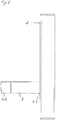
- eine Verriegelungsvorrichtung in einer perspektivischen Ansicht;
- Fig. 2
- eine Verriegelungsvorrichtung mit ausgeschwenktem Riegel;
- Fig. 3
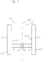
- eine Doppelpendeltür mit einer Verriegelungsvorrichtung.
- In der
Fig. 1 ist eine Verriegelungsvorrichtung in einer perspektivischen Ansicht dargestellt. Die Verriegelungsvorrichtung 1 zum Sperren einer Tür in der geschlossenen Position umfasst mindestens einen Türgriff 2, wobei der Türgriff 2 aus einem Basiskörper 2.1 und einen Griffkörper 2.3 besteht, wobei der Basiskörper 2.1 an der Tür befestigbar ist. Die Tür selber ist aber nicht dargestellt. Die Form des Griffkörpers ist dabei unerheblich, der Griffkörper muss nur genügend Platz für eine Ausnehmung zur Aufnahme eines Sperrgliedes aufweisen. Es kann sich um einen Block- oder Bügelgriff oder um einen Knauf- oder Knopfgriff handeln. - Der Griffkörper 2.3 des Türgriffs 10 umfasst eine Ausnehmung 2.3.1 zur Aufnahme eines aus einer vertikalen in eine horizontale Position schwenkbar gehaltenen Riegels 3, wobei der Riegel 3 in der horizontalen Position durch ein Sperrmittel 3.2 arretierbar ist. Bei dem Sperrmittel 3.2 handelt es z.B. um Zargen, die mit einem zweiten Sperrmittel 4 an einem Türrahmen 11 zur Verriegelung der Tür in einem Wirkungszusammenhang stehen, wobei die Zargen dann in dort vorgesehene Schlitze eingreifen. Im Griffkörper 2.3 ist dabei vorteilhaft ein Mechanismus 2.3.2 integriert, der den Riegel 3 um eine Schwenkachse aus einer Verriegelungsposition, in der die Tür 10 gegen ein Öffnen verriegelt ist, in eine Entriegelungsposition, in der die Türe 10 geöffnet werden kann, schwenkt. Der Mechanismus 2.3.2 umfasst ein Arretiermittel 2.3.2.1, welches in der Verriegelungsposition mit einem Rastabschnitt 3.1 des Riegels 3 zusammenwirkt. In der
Fig. 3 ist eine Doppelpendeltür mit einer Verriegelungsvorrichtung schematisch dargestellt, wobei jede Tür 10, 10' einen Türgriff 2, 2'aufweist. Die Ausnehmungen 2.3.1, 2.3.1' der Griffkörper 2.3, 2.3' sind parallel gegenüberliegend angeordnet, wobei die Sperrmittel 3.2, 3.2' der Riegel 3, 3' in der horizontalen Position ineinandergreifen und somit die Doppelpendeltür 100 sperren.
Claims (3)
- Doppelpendeltür mit einer Verriegelungsvorrichtung wobei jede Tür (10, 10') einen Türgriff (2, 2') aufweist, wobei die Türgriffe (2, 2') aus einem Basiskörper (2.1, 2.1') und einen Griffkörper (2.3, 2.3') bestehen, wobei die Basiskörper (2.1, 2.1) an der Tür (100) befestigbar sind, wobei die Griffkörper (2.3, 2.3') der Türgriffe (10, 10') Ausnehmungen (2.3.1, 2.3.1') zur Aufnahme eines aus einer vertikalen in eine horizontale Position schwenkbar gehaltenen Riegels (3, 3') umfassen, wobei die Riegel (3, 3') in der horizontalen Position durch Sperrmittel (3.2, 3.2') arretierbar sind, wobei die Ausnehmungen (2.3.1, 2.3.1') der Griffkörper (2.3, 2.3') parallel gegenüberliegend angeordnet sind und die Sperrmittel (3.2, 3.2') der Riegel (3, 3') in der horizontalen Position ineinandergreifen und somit die Doppelpendeltür (100) sperren.
- Doppelpendeltür nach Anspruch 1, dadurch gekennzeichnet, dass im Griffkörper (2.3, 2.3') ein Mechanismus (2.3.2, 2.3.2') integriert ist, der den Riegel (3, 3') um eine Schwenkachse aus einer Verriegelungsposition, in der die Tür (100) gegen ein Öffnen verriegelt ist, in eine Entriegelungsposition, in der die Türe (100) geöffnet werden kann, schwenkt.
- Doppelpendeltür nach Anspruch 2, dadurch gekennzeichnet, dass der Mechanismus (2.3.2, 2.3.2') ein Arretiermittel (2.3.2.1, 2.3.2.1') umfasst, welches in der Verriegelungsposition mit einem Rastabschnitt (3.1, 3.1') des Riegels (3, 3') zusammenwirkt.
Priority Applications (1)
| Application Number | Priority Date | Filing Date | Title |
|---|---|---|---|
| PL19189808T PL3617434T3 (pl) | 2018-08-27 | 2019-08-02 | Podwójne drzwi wahadłowe wyposażone w urządzenie ryglujące |
Applications Claiming Priority (1)
| Application Number | Priority Date | Filing Date | Title |
|---|---|---|---|
| DE102018214389.7A DE102018214389B3 (de) | 2018-08-27 | 2018-08-27 | Verriegelungsvorrichtung zum Sperren einer Tür |
Publications (2)
| Publication Number | Publication Date |
|---|---|
| EP3617434A1 EP3617434A1 (de) | 2020-03-04 |
| EP3617434B1 true EP3617434B1 (de) | 2021-04-14 |
Family
ID=67544020
Family Applications (1)
| Application Number | Title | Priority Date | Filing Date |
|---|---|---|---|
| EP19189808.9A Active EP3617434B1 (de) | 2018-08-27 | 2019-08-02 | Doppelpendeltür mit einer verriegelungsvorrichtung |
Country Status (3)
| Country | Link |
|---|---|
| EP (1) | EP3617434B1 (de) |
| DE (1) | DE102018214389B3 (de) |
| PL (1) | PL3617434T3 (de) |
Family Cites Families (12)
| Publication number | Priority date | Publication date | Assignee | Title |
|---|---|---|---|---|
| US1627752A (en) | 1925-09-22 | 1927-05-10 | Sylvester J Small | Door fastener |
| FR1118537A (fr) * | 1955-01-04 | 1956-06-07 | Verrouillage pour fermeture de portes ou de panneaux démontables | |
| DE7209463U (de) | 1972-03-13 | 1972-05-31 | Fahrner M | Tuergriff fuer selbsttaetig schliessende pendeltueren |
| DE3034095A1 (de) | 1980-09-10 | 1982-04-15 | Dieter Dipl.-Ing. 7952 Renchen Dieckmann | Tuergriff |
| DE3243029C3 (de) * | 1982-11-20 | 1998-01-29 | Dieter Ramsauer | Versenkbarer Verschluß für Schaltschranktüren |
| DE69012685T2 (de) | 1989-07-11 | 1995-05-04 | Fruehauf Japan | Verriegelungskonstruktion eines Griffes für das Schliessen und Öffnen einer Türe. |
| DE202006003304U1 (de) * | 2006-03-02 | 2007-07-05 | Dirak Dieter Ramsauer Konstruktionselemente Gmbh & Co. Kg | Griff mit Verschlußeinsatz |
| JP4895706B2 (ja) * | 2006-07-19 | 2012-03-14 | 三洋電機株式会社 | ショーケース |
| US8038100B2 (en) * | 2007-09-21 | 2011-10-18 | Honda Motor Co., Ltd. | Paneled partition with track for linear and rotational movement |
| US20100096863A1 (en) * | 2008-10-16 | 2010-04-22 | Alco Ventures Inc. | Mechanical latch assembly for retractable screen doors and windows |
| DE202009001785U1 (de) | 2009-02-12 | 2009-04-09 | Gebhardt Transport- Und Lagersysteme Gmbh | Türhebelmechanismus |
| KR101320437B1 (ko) | 2011-12-05 | 2013-10-23 | 이영아 | 손잡이형 도어잠금장치 |
-
2018
- 2018-08-27 DE DE102018214389.7A patent/DE102018214389B3/de not_active Expired - Fee Related
-
2019
- 2019-08-02 PL PL19189808T patent/PL3617434T3/pl unknown
- 2019-08-02 EP EP19189808.9A patent/EP3617434B1/de active Active
Non-Patent Citations (1)
| Title |
|---|
| None * |
Also Published As
| Publication number | Publication date |
|---|---|
| DE102018214389B3 (de) | 2019-10-10 |
| EP3617434A1 (de) | 2020-03-04 |
| PL3617434T3 (pl) | 2021-10-25 |
Similar Documents
| Publication | Publication Date | Title |
|---|---|---|
| DE8915994U1 (de) | Kraftfahrzeugtürverschluß mit einem Zentralverriegelungsantrieb | |
| DE69408012T2 (de) | Schloss für Notausgang, anpassbar an die Türöffnungsrichtung, mit einer Handhabe auf der einen Seite und eine Möglichkeit zum befristeten Öffnen auf der anderen Seite | |
| EP0954663A1 (de) | Durch vorhängeschloss sicherbare schwenkhebelbetätigung für den verschluss von schaltschranktüren oder dgl. | |
| DE102017112497A1 (de) | Sicherheitsgriff mit Hebelwirkung | |
| EP0941391A1 (de) | Durch vorhängeschloss sicherbare schwenkhebelbetätigung für den verschluss von schaltschranktüren oder dgl. | |
| EP3760387B1 (de) | Verschlusskasten | |
| EP3617434B1 (de) | Doppelpendeltür mit einer verriegelungsvorrichtung | |
| DE4023822A1 (de) | Schloss mit kindersicherung fuer kraftfahrzeugtueren | |
| DE4434715A1 (de) | Türschloß für Fahrzeuge | |
| EP3887621A1 (de) | Modulares verschlusssystem | |
| DE202016104019U1 (de) | Schwenkhebelverschluss | |
| EP3222801A1 (de) | Schloss für wertbehältnisse | |
| DE102017119835A1 (de) | Verschlussvorrichtung | |
| DE102017009817A1 (de) | Verschließeinrichtung und -mechanismus insbesondere zur Sicherung von flächigen, zweigliedrigen Verbindungshalterungen (z.B. Schubverschlüssen) | |
| DE3213668A1 (de) | Vorrichtung zum oeffnen von paniktueren | |
| DE4403834C1 (de) | Schließvorrichtung | |
| DE318322C (de) | ||
| DE102009005912B4 (de) | Anordnung zur Verriegelung einer Tischtennisplatte | |
| DE102005001062A1 (de) | Anordnung zur Verriegelung eines Tischtennisspieles | |
| DE212454C (de) | ||
| DE141332C (de) | ||
| DE4240149C2 (de) | Riegelwerk | |
| DE256103C (de) | ||
| DE102021100427A1 (de) | Betätigungsschlüssel | |
| DE287425C (de) |
Legal Events
| Date | Code | Title | Description |
|---|---|---|---|
| PUAI | Public reference made under article 153(3) epc to a published international application that has entered the european phase |
Free format text: ORIGINAL CODE: 0009012 |
|
| STAA | Information on the status of an ep patent application or granted ep patent |
Free format text: STATUS: THE APPLICATION HAS BEEN PUBLISHED |
|
| AK | Designated contracting states |
Kind code of ref document: A1 Designated state(s): AL AT BE BG CH CY CZ DE DK EE ES FI FR GB GR HR HU IE IS IT LI LT LU LV MC MK MT NL NO PL PT RO RS SE SI SK SM TR |
|
| AX | Request for extension of the european patent |
Extension state: BA ME |
|
| STAA | Information on the status of an ep patent application or granted ep patent |
Free format text: STATUS: REQUEST FOR EXAMINATION WAS MADE |
|
| 17P | Request for examination filed |
Effective date: 20200827 |
|
| RBV | Designated contracting states (corrected) |
Designated state(s): AL AT BE BG CH CY CZ DE DK EE ES FI FR GB GR HR HU IE IS IT LI LT LU LV MC MK MT NL NO PL PT RO RS SE SI SK SM TR |
|
| RIC1 | Information provided on ipc code assigned before grant |
Ipc: E05C 7/00 20060101ALI20201111BHEP Ipc: E05B 1/00 20060101ALI20201111BHEP Ipc: E05B 63/12 20060101ALI20201111BHEP Ipc: E05B 65/06 20060101ALI20201111BHEP Ipc: E05C 3/02 20060101AFI20201111BHEP |
|
| GRAP | Despatch of communication of intention to grant a patent |
Free format text: ORIGINAL CODE: EPIDOSNIGR1 |
|
| STAA | Information on the status of an ep patent application or granted ep patent |
Free format text: STATUS: GRANT OF PATENT IS INTENDED |
|
| INTG | Intention to grant announced |
Effective date: 20201221 |
|
| GRAS | Grant fee paid |
Free format text: ORIGINAL CODE: EPIDOSNIGR3 |
|
| GRAA | (expected) grant |
Free format text: ORIGINAL CODE: 0009210 |
|
| STAA | Information on the status of an ep patent application or granted ep patent |
Free format text: STATUS: THE PATENT HAS BEEN GRANTED |
|
| AK | Designated contracting states |
Kind code of ref document: B1 Designated state(s): AL AT BE BG CH CY CZ DE DK EE ES FI FR GB GR HR HU IE IS IT LI LT LU LV MC MK MT NL NO PL PT RO RS SE SI SK SM TR |
|
| REG | Reference to a national code |
Ref country code: GB Ref legal event code: FG4D Free format text: NOT ENGLISH |
|
| REG | Reference to a national code |
Ref country code: CH Ref legal event code: EP |
|
| REG | Reference to a national code |
Ref country code: DE Ref legal event code: R096 Ref document number: 502019001217 Country of ref document: DE |
|
| REG | Reference to a national code |
Ref country code: IE Ref legal event code: FG4D Free format text: LANGUAGE OF EP DOCUMENT: GERMAN |
|
| REG | Reference to a national code |
Ref country code: AT Ref legal event code: REF Ref document number: 1382516 Country of ref document: AT Kind code of ref document: T Effective date: 20210515 |
|
| REG | Reference to a national code |
Ref country code: NL Ref legal event code: FP |
|
| REG | Reference to a national code |
Ref country code: LT Ref legal event code: MG9D |
|
| PG25 | Lapsed in a contracting state [announced via postgrant information from national office to epo] |
Ref country code: LT Free format text: LAPSE BECAUSE OF FAILURE TO SUBMIT A TRANSLATION OF THE DESCRIPTION OR TO PAY THE FEE WITHIN THE PRESCRIBED TIME-LIMIT Effective date: 20210414 Ref country code: HR Free format text: LAPSE BECAUSE OF FAILURE TO SUBMIT A TRANSLATION OF THE DESCRIPTION OR TO PAY THE FEE WITHIN THE PRESCRIBED TIME-LIMIT Effective date: 20210414 Ref country code: FI Free format text: LAPSE BECAUSE OF FAILURE TO SUBMIT A TRANSLATION OF THE DESCRIPTION OR TO PAY THE FEE WITHIN THE PRESCRIBED TIME-LIMIT Effective date: 20210414 Ref country code: BG Free format text: LAPSE BECAUSE OF FAILURE TO SUBMIT A TRANSLATION OF THE DESCRIPTION OR TO PAY THE FEE WITHIN THE PRESCRIBED TIME-LIMIT Effective date: 20210714 |
|
| PG25 | Lapsed in a contracting state [announced via postgrant information from national office to epo] |
Ref country code: SE Free format text: LAPSE BECAUSE OF FAILURE TO SUBMIT A TRANSLATION OF THE DESCRIPTION OR TO PAY THE FEE WITHIN THE PRESCRIBED TIME-LIMIT Effective date: 20210414 Ref country code: PT Free format text: LAPSE BECAUSE OF FAILURE TO SUBMIT A TRANSLATION OF THE DESCRIPTION OR TO PAY THE FEE WITHIN THE PRESCRIBED TIME-LIMIT Effective date: 20210816 Ref country code: RS Free format text: LAPSE BECAUSE OF FAILURE TO SUBMIT A TRANSLATION OF THE DESCRIPTION OR TO PAY THE FEE WITHIN THE PRESCRIBED TIME-LIMIT Effective date: 20210414 Ref country code: NO Free format text: LAPSE BECAUSE OF FAILURE TO SUBMIT A TRANSLATION OF THE DESCRIPTION OR TO PAY THE FEE WITHIN THE PRESCRIBED TIME-LIMIT Effective date: 20210714 Ref country code: LV Free format text: LAPSE BECAUSE OF FAILURE TO SUBMIT A TRANSLATION OF THE DESCRIPTION OR TO PAY THE FEE WITHIN THE PRESCRIBED TIME-LIMIT Effective date: 20210414 Ref country code: IS Free format text: LAPSE BECAUSE OF FAILURE TO SUBMIT A TRANSLATION OF THE DESCRIPTION OR TO PAY THE FEE WITHIN THE PRESCRIBED TIME-LIMIT Effective date: 20210814 Ref country code: GR Free format text: LAPSE BECAUSE OF FAILURE TO SUBMIT A TRANSLATION OF THE DESCRIPTION OR TO PAY THE FEE WITHIN THE PRESCRIBED TIME-LIMIT Effective date: 20210715 |
|
| REG | Reference to a national code |
Ref country code: DE Ref legal event code: R097 Ref document number: 502019001217 Country of ref document: DE |
|
| PG25 | Lapsed in a contracting state [announced via postgrant information from national office to epo] |
Ref country code: EE Free format text: LAPSE BECAUSE OF FAILURE TO SUBMIT A TRANSLATION OF THE DESCRIPTION OR TO PAY THE FEE WITHIN THE PRESCRIBED TIME-LIMIT Effective date: 20210414 Ref country code: ES Free format text: LAPSE BECAUSE OF FAILURE TO SUBMIT A TRANSLATION OF THE DESCRIPTION OR TO PAY THE FEE WITHIN THE PRESCRIBED TIME-LIMIT Effective date: 20210414 Ref country code: SK Free format text: LAPSE BECAUSE OF FAILURE TO SUBMIT A TRANSLATION OF THE DESCRIPTION OR TO PAY THE FEE WITHIN THE PRESCRIBED TIME-LIMIT Effective date: 20210414 Ref country code: SM Free format text: LAPSE BECAUSE OF FAILURE TO SUBMIT A TRANSLATION OF THE DESCRIPTION OR TO PAY THE FEE WITHIN THE PRESCRIBED TIME-LIMIT Effective date: 20210414 Ref country code: RO Free format text: LAPSE BECAUSE OF FAILURE TO SUBMIT A TRANSLATION OF THE DESCRIPTION OR TO PAY THE FEE WITHIN THE PRESCRIBED TIME-LIMIT Effective date: 20210414 Ref country code: DK Free format text: LAPSE BECAUSE OF FAILURE TO SUBMIT A TRANSLATION OF THE DESCRIPTION OR TO PAY THE FEE WITHIN THE PRESCRIBED TIME-LIMIT Effective date: 20210414 |
|
| PLBE | No opposition filed within time limit |
Free format text: ORIGINAL CODE: 0009261 |
|
| STAA | Information on the status of an ep patent application or granted ep patent |
Free format text: STATUS: NO OPPOSITION FILED WITHIN TIME LIMIT |
|
| 26N | No opposition filed |
Effective date: 20220117 |
|
| PG25 | Lapsed in a contracting state [announced via postgrant information from national office to epo] |
Ref country code: MC Free format text: LAPSE BECAUSE OF FAILURE TO SUBMIT A TRANSLATION OF THE DESCRIPTION OR TO PAY THE FEE WITHIN THE PRESCRIBED TIME-LIMIT Effective date: 20210414 |
|
| PG25 | Lapsed in a contracting state [announced via postgrant information from national office to epo] |
Ref country code: IS Free format text: LAPSE BECAUSE OF FAILURE TO SUBMIT A TRANSLATION OF THE DESCRIPTION OR TO PAY THE FEE WITHIN THE PRESCRIBED TIME-LIMIT Effective date: 20210814 Ref country code: AL Free format text: LAPSE BECAUSE OF FAILURE TO SUBMIT A TRANSLATION OF THE DESCRIPTION OR TO PAY THE FEE WITHIN THE PRESCRIBED TIME-LIMIT Effective date: 20210414 |
|
| PG25 | Lapsed in a contracting state [announced via postgrant information from national office to epo] |
Ref country code: IT Free format text: LAPSE BECAUSE OF FAILURE TO SUBMIT A TRANSLATION OF THE DESCRIPTION OR TO PAY THE FEE WITHIN THE PRESCRIBED TIME-LIMIT Effective date: 20210414 Ref country code: IE Free format text: LAPSE BECAUSE OF NON-PAYMENT OF DUE FEES Effective date: 20210802 |
|
| PGFP | Annual fee paid to national office [announced via postgrant information from national office to epo] |
Ref country code: LU Payment date: 20220823 Year of fee payment: 4 Ref country code: CZ Payment date: 20220801 Year of fee payment: 4 |
|
| PGFP | Annual fee paid to national office [announced via postgrant information from national office to epo] |
Ref country code: PL Payment date: 20220720 Year of fee payment: 4 Ref country code: FR Payment date: 20220824 Year of fee payment: 4 |
|
| PGFP | Annual fee paid to national office [announced via postgrant information from national office to epo] |
Ref country code: CH Payment date: 20220824 Year of fee payment: 4 |
|
| PG25 | Lapsed in a contracting state [announced via postgrant information from national office to epo] |
Ref country code: CY Free format text: LAPSE BECAUSE OF FAILURE TO SUBMIT A TRANSLATION OF THE DESCRIPTION OR TO PAY THE FEE WITHIN THE PRESCRIBED TIME-LIMIT Effective date: 20210414 |
|
| PG25 | Lapsed in a contracting state [announced via postgrant information from national office to epo] |
Ref country code: HU Free format text: LAPSE BECAUSE OF FAILURE TO SUBMIT A TRANSLATION OF THE DESCRIPTION OR TO PAY THE FEE WITHIN THE PRESCRIBED TIME-LIMIT; INVALID AB INITIO Effective date: 20190802 |
|
| REG | Reference to a national code |
Ref country code: CH Ref legal event code: PL |
|
| PG25 | Lapsed in a contracting state [announced via postgrant information from national office to epo] |
Ref country code: LU Free format text: LAPSE BECAUSE OF NON-PAYMENT OF DUE FEES Effective date: 20230802 |
|
| GBPC | Gb: european patent ceased through non-payment of renewal fee |
Effective date: 20230802 |
|
| PG25 | Lapsed in a contracting state [announced via postgrant information from national office to epo] |
Ref country code: MK Free format text: LAPSE BECAUSE OF FAILURE TO SUBMIT A TRANSLATION OF THE DESCRIPTION OR TO PAY THE FEE WITHIN THE PRESCRIBED TIME-LIMIT Effective date: 20210414 Ref country code: LU Free format text: LAPSE BECAUSE OF NON-PAYMENT OF DUE FEES Effective date: 20230802 Ref country code: CZ Free format text: LAPSE BECAUSE OF NON-PAYMENT OF DUE FEES Effective date: 20230802 Ref country code: CH Free format text: LAPSE BECAUSE OF NON-PAYMENT OF DUE FEES Effective date: 20230831 |
|
| PG25 | Lapsed in a contracting state [announced via postgrant information from national office to epo] |
Ref country code: GB Free format text: LAPSE BECAUSE OF NON-PAYMENT OF DUE FEES Effective date: 20230802 |
|
| PG25 | Lapsed in a contracting state [announced via postgrant information from national office to epo] |
Ref country code: GB Free format text: LAPSE BECAUSE OF NON-PAYMENT OF DUE FEES Effective date: 20230802 Ref country code: FR Free format text: LAPSE BECAUSE OF NON-PAYMENT OF DUE FEES Effective date: 20230831 |
|
| PGFP | Annual fee paid to national office [announced via postgrant information from national office to epo] |
Ref country code: NL Payment date: 20240708 Year of fee payment: 6 |
|
| PG25 | Lapsed in a contracting state [announced via postgrant information from national office to epo] |
Ref country code: MT Free format text: LAPSE BECAUSE OF FAILURE TO SUBMIT A TRANSLATION OF THE DESCRIPTION OR TO PAY THE FEE WITHIN THE PRESCRIBED TIME-LIMIT Effective date: 20210414 |
|
| PGFP | Annual fee paid to national office [announced via postgrant information from national office to epo] |
Ref country code: DE Payment date: 20240831 Year of fee payment: 6 |
|
| PGFP | Annual fee paid to national office [announced via postgrant information from national office to epo] |
Ref country code: BE Payment date: 20240708 Year of fee payment: 6 |
|
| PGFP | Annual fee paid to national office [announced via postgrant information from national office to epo] |
Ref country code: AT Payment date: 20240708 Year of fee payment: 6 |
|
| PG25 | Lapsed in a contracting state [announced via postgrant information from national office to epo] |
Ref country code: PL Free format text: LAPSE BECAUSE OF NON-PAYMENT OF DUE FEES Effective date: 20230802 |
|
| PG25 | Lapsed in a contracting state [announced via postgrant information from national office to epo] |
Ref country code: PL Free format text: LAPSE BECAUSE OF NON-PAYMENT OF DUE FEES Effective date: 20230802 |
|
| REG | Reference to a national code |
Ref country code: DE Ref legal event code: R081 Ref document number: 502019001217 Country of ref document: DE Owner name: KERMI DUSCHDESIGN GMBH, DE Free format text: FORMER OWNER: KERMI GMBH, 94447 PLATTLING, DE |
|
| PG25 | Lapsed in a contracting state [announced via postgrant information from national office to epo] |
Ref country code: TR Free format text: LAPSE BECAUSE OF FAILURE TO SUBMIT A TRANSLATION OF THE DESCRIPTION OR TO PAY THE FEE WITHIN THE PRESCRIBED TIME-LIMIT Effective date: 20210414 |
|
| REG | Reference to a national code |
Ref country code: DE Ref legal event code: R119 Ref document number: 502019001217 Country of ref document: DE |
|
| REG | Reference to a national code |
Ref country code: NL Ref legal event code: MM Effective date: 20250901 |
|
| PG25 | Lapsed in a contracting state [announced via postgrant information from national office to epo] |
Ref country code: AT Free format text: LAPSE BECAUSE OF NON-PAYMENT OF DUE FEES Effective date: 20250802 |
|
| REG | Reference to a national code |
Ref country code: AT Ref legal event code: MM01 Ref document number: 1382516 Country of ref document: AT Kind code of ref document: T Effective date: 20250802 |