EP3617520A1 - Vakuumgerät, zubehöreinheit und system - Google Patents
Vakuumgerät, zubehöreinheit und system Download PDFInfo
- Publication number
- EP3617520A1 EP3617520A1 EP18191876.4A EP18191876A EP3617520A1 EP 3617520 A1 EP3617520 A1 EP 3617520A1 EP 18191876 A EP18191876 A EP 18191876A EP 3617520 A1 EP3617520 A1 EP 3617520A1
- Authority
- EP
- European Patent Office
- Prior art keywords
- connection
- accessory unit
- vacuum device
- unit
- accessory
- Prior art date
- Legal status (The legal status is an assumption and is not a legal conclusion. Google has not performed a legal analysis and makes no representation as to the accuracy of the status listed.)
- Granted
Links
Images


Classifications
-
- F—MECHANICAL ENGINEERING; LIGHTING; HEATING; WEAPONS; BLASTING
- F04—POSITIVE - DISPLACEMENT MACHINES FOR LIQUIDS; PUMPS FOR LIQUIDS OR ELASTIC FLUIDS
- F04D—NON-POSITIVE-DISPLACEMENT PUMPS
- F04D19/00—Axial-flow pumps
- F04D19/02—Multi-stage pumps
- F04D19/04—Multi-stage pumps specially adapted to the production of a high vacuum, e.g. molecular pumps
-
- F—MECHANICAL ENGINEERING; LIGHTING; HEATING; WEAPONS; BLASTING
- F04—POSITIVE - DISPLACEMENT MACHINES FOR LIQUIDS; PUMPS FOR LIQUIDS OR ELASTIC FLUIDS
- F04D—NON-POSITIVE-DISPLACEMENT PUMPS
- F04D17/00—Radial-flow pumps, e.g. centrifugal pumps; Helico-centrifugal pumps
- F04D17/08—Centrifugal pumps
- F04D17/16—Centrifugal pumps for displacing without appreciable compression
- F04D17/168—Pumps specially adapted to produce a vacuum
-
- F—MECHANICAL ENGINEERING; LIGHTING; HEATING; WEAPONS; BLASTING
- F04—POSITIVE - DISPLACEMENT MACHINES FOR LIQUIDS; PUMPS FOR LIQUIDS OR ELASTIC FLUIDS
- F04D—NON-POSITIVE-DISPLACEMENT PUMPS
- F04D25/00—Pumping installations or systems
- F04D25/02—Units comprising pumps and their driving means
- F04D25/06—Units comprising pumps and their driving means the pump being electrically driven
- F04D25/068—Mechanical details of the pump control unit
-
- F—MECHANICAL ENGINEERING; LIGHTING; HEATING; WEAPONS; BLASTING
- F04—POSITIVE - DISPLACEMENT MACHINES FOR LIQUIDS; PUMPS FOR LIQUIDS OR ELASTIC FLUIDS
- F04D—NON-POSITIVE-DISPLACEMENT PUMPS
- F04D27/00—Control, e.g. regulation, of pumps, pumping installations or pumping systems specially adapted for elastic fluids
- F04D27/001—Testing thereof; Determination or simulation of flow characteristics; Stall or surge detection, e.g. condition monitoring
Definitions
- the present invention relates to a vacuum device, in particular a vacuum pump, with at least one connection for an accessory unit and with a control unit for the accessory unit.
- the invention also relates to an accessory unit for a vacuum device, in particular a vacuum pump, with a connection for connection to a connection of the vacuum device.
- the invention also relates to a system with a vacuum device and an accessory unit.
- one or more connections are each provided for an accessory unit. After connection to the connection, the accessory unit is operated by a control unit of the vacuum device.
- control unit is designed to recognize the type of an accessory unit connected to the connection.
- connection of the accessory unit can be carried out particularly easily, in particular without manual or other external configuration.
- the operation of the vacuum device is also particularly flexible as a result of the accessories can be connected, disconnected and / or replaced without great effort and as required.
- a particularly convenient operation in the sense of a "plug and play" concept is realized, as is known from the remote technical field of personal computers. From the user's point of view, a connected accessory unit advantageously gains its function simply by connecting to the connection. Knowing the type of accessory unit, the control unit can control it as required.
- control unit can recognize the accessory unit on the basis of a label and call up further information, such as maximum tolerable voltage, from a stored table.
- control unit immediately recognizes the necessary information, in particular on the basis of a signal emitted by the accessory unit.
- the connection can have at least one communication contact for communicatively connecting the accessory unit to the control unit.
- This does not necessarily mean a metallic and / or electrical contact, but generally a connection point for wired communication.
- an optical contact for example for an optical waveguide, can also be provided.
- a communication interface in particular wireless, that is separate from the connection can also be provided.
- the communication contact can also be used for communication with other units that are not accessory units, for example for communication with a configuration and / or diagnostic unit, a further vacuum device and / or a process control system.
- a separate interface such as a diagnostic or configuration interface, can then advantageously be dispensed with.
- several communication contacts, in particular per connection, can also be provided.
- connection has at least one supply contact for the electrical supply of the accessory unit.
- the accessory unit therefore does not require an additional power connection, which simplifies the arrangement.
- a driver can be provided for the supply contact or for the connection. This can advantageously be designed in such a way that accessory units from older device generations can also be operated reliably, in particular without means for sending out detection signals.
- the control unit can be designed to supply the accessory unit with different voltages, in particular via the supply contact. In the simplest case, these are two different voltages, in particular zero and a general operating voltage for all accessories. At least two non-zero different voltages are particularly advantageous. In this way, the connection of accessory units can be made more flexible, since they can be supplied as required without the need for a transformer on the accessory unit.
- the control unit is designed to apply a first non-zero voltage, for example 5 V, in principle, in particular to the connection or to the supply contact, and, after detection and / or communication with the accessory unit, another voltage suitable for the accessory unit Voltage, for example 24 V, to apply.
- a specific supply voltage is permanently present, for example at the supply contact.
- the accessory unit controls itself more advantageously Way itself, in particular depending on commands or data specified by the control unit, which are advantageously transmitted via a communication contact of the connection. This simplifies the vacuum device and control unit technically.
- the supply contact can be used, for example, both to supply energy to the accessory unit and as a mere switching means for actuating a switch, such as a relay.
- a switch such as a relay.
- the accessory unit can be a backing pump for the vacuum device designed here as a vacuum pump. This backing pump requires a relatively large output, which could only be provided with a special technical effort by the vacuum device. On top of this, this leads to an increased installation space, which is often undesirable. In this example, the energy supply to the accessory unit is thus advantageously outsourced.
- a vacuum device Insofar as a vacuum device is described above as a unit different from the accessory unit, this relates to vacuum devices which are not intended as accessories for the vacuum device according to the invention, but are operated in a subordinate manner.
- the backing pump described here is subordinate to the vacuum pump and dependent.
- the backing pump is also controlled via the supply contact. In principle, however, it can also be controlled via a communication contact or other means of communication.
- the connection according to the invention can be designed and used in a variety of ways. Control and / or communication can be implemented for numerous units, in particular starting from the control unit. In all this, the automatic recognition of the accessory unit according to the invention by the control unit ensures a completely new flexibility and simplicity.
- control unit is designed to control the accessory unit as a function of parameters of the vacuum device.
- the speed is controlled as a function of a temperature in or on the vacuum device. This control can take place, on the one hand, via a supply contact and, on the other hand, via a communication contact, in which case the accessory unit is then prompted to adjust the speed itself.
- the vacuum device and / or accessory unit are even designed such that both are possible.
- a common contact can also be provided as a communication contact and supply contact. Communication and supply are then also possible via the same line. This proves to be particularly advantageous in terms of compatibility. This means that existing connections do not need to be redesigned. In addition, the construction is and remains simple.
- control unit is designed to recognize the type of accessory unit from a signal emanating from the accessory unit.
- the signal can include, for example, an identifier and / or information that directly relates to parameters of the accessory unit, such as the operating voltage.
- the signal can be made available, for example, via a communication contact of the connection of the control unit. This enables particularly simple operation. Alternatively or additionally, the signal can also be made available independently of the connection, in particular via an additional connection and / or wirelessly.
- a serial interface for the accessory unit can be provided at the connection. This enables particularly reliable communication to be implemented in a simple manner.
- a bus interface for the accessory unit can be provided at the connection. This enables particularly flexible operation for a large number of accessory units.
- the accessory units can be controlled individually and / or in groups. In particular, the number of accessory units can be expanded.
- control unit can recognize an assignment of the connected accessory units to the respective connection, for example via a topology, that is to say via direct or assigned individual wiring between the control unit and the respective connections. Alternatively, however, an assignment can also be made via a bus system.
- control unit is designed to process useful data provided by the accessory unit.
- data that is different from recognition data are considered as useful data.
- user data include sensor data.
- the accessory unit can include a sensor and provide its information either analog or digital, in particular via the connection. It is possible with a cost advantage to dispense with a separate converter provided for the sensor. This not only saves a converter, but generally available parts can also be operated with the control unit without major technical adjustments.
- control unit is designed to operate the accessory unit, even if the control unit does not recognize the type of the accessory unit.
- an input unit for inputting the type of accessory unit to the control unit can be provided.
- input can also be made via an additional connection for an accessory unit, it being possible for an input unit or a communication unit for receiving an input unit to be connected or connected to this connector as an accessory unit.
- control unit can be designed to operate more than one accessory unit connected to the connection at the same time.
- at least one accessory unit directly connected or connectable to the connector can have at least one additional connector for connecting at least one additional accessory unit.
- the additional connection can either be connected directly to the first connection of the accessory unit, or else can be connected via a processing unit, for example a microprocessor, for example via the forwarding of data and / or voltage from a priority connected accessory unit for one or more subsequent accessory units can be decided.
- an adapter can also be provided for the parallel connection of at least two accessory units to one connection.
- recognition and / or assignment can take place via address selection switches or preprogrammed addresses.
- an accessory unit can also be connected via several connections, for example by one to realize greater performance, in particular on the supply contacts, and / or a greater communication data rate, in particular on a communication contact.
- control unit can comprise a motor controller for the vacuum device, in particular a vacuum pump, or can be part of one.
- the control unit can be designed separately from an engine control and / or separately from other control elements.
- One or more separate control units can each be provided for one or more connections.
- a control unit can be provided for a connection, and in particular adjacent to or integrated in it. It is advantageous here that the control unit, in particular via the connection, can also be contacted and read out when the motor control or the other control element is not attached. This leads to a further flexibility in the operation and maintenance of the vacuum device or a vacuum system.
- a connection can, for example, be male or female and / or comprise a plug or a socket, other types of connection also being conceivable.
- the object of the invention is also achieved by an accessory unit with the features of the independent claim directed thereon, and in particular in that the accessory unit is designed to output a signal, in particular via the connection, in particular via a communication contact, on the basis of which the accessory unit in its Is recognizable.
- the accessory unit can comprise, for example, a heating element, a fan, a flood valve, a sealing gas valve, a control relay, for example for a backing pump, a pressure measuring device and / or a, in particular integrated, measuring tube. More generally, the accessory unit can include, for example, at least one actuator and / or sensor. But accessories with other functional elements are also conceivable.
- an accessory unit can also include a storage element for storing data. This can be used, for example, to record data from pump data over a longer period of time.
- the accessory unit comprises both an actuator and a sensor, in particular for a parameter that can be influenced by the actuator.
- the accessory unit is in particular and is designed to output data, in particular user data, from the sensor via the connection.
- parameters that can be influenced by actuators are a temperature on a heating element and a speed on a fan.
- the sensor data can advantageously be used for a functional check of the actuator or also for controlling it depending on the sensor data.
- the accessory unit itself can also have an interface for communication with further devices or units.
- the accessory unit includes a wireless interface.
- it can form a radio module, by means of which a wireless connection can be flexibly retrofitted to a vacuum device.
- the wireless interface can, for example, be designed in accordance with at least one of the standards for GSM, UMTS, LTE and / or other mobile radio standards, Bluetooth, NFC and / or WLAN.
- the accessory unit can in this way one or more other devices, e.g. themselves represent an accessory unit for a vacuum device, in particular according to the invention, read, control, recognize, etc. by radio - generally wirelessly -
- the accessory unit can advantageously be designed so that it can also be operated by a control unit of the vacuum device when the latter is the accessory unit does not recognize in its nature, for example because the vacuum device has no detection means.
- a control unit of the vacuum device when the latter is the accessory unit does not recognize in its nature, for example because the vacuum device has no detection means.
- the accessory unit can be designed, for example, to recognize the fact of non-detection itself, for example by the unsuccessful attempt to establish communication with the control unit, in particular via a communication contact of the connection.
- the accessory unit has at least one second connection for connecting a further accessory unit to the accessory unit and / or to the vacuum device.
- the second connection and its contacts can be connected directly to the first connection, and in particular the contacts and the accessory unit can be designed for connection to a bus system.
- a processing unit of the accessory unit can also be connected between the connections.
- the accessory unit can, for example, prevent the information and / or voltages from being forwarded and / or change them.
- connection of the vacuum device and / or the accessory unit can be designed, for example, both for a mechanical connection and for an electrical and / or information technology connection of the accessory unit to the control unit. This enables a particularly flexible connection.
- the object is also achieved by a recognition unit with the features of the independent claim directed thereon.
- the detection unit can, for example, advantageously be used to retrofit an older accessory unit.
- the signal can be output in particular via the first connection, in particular via a communication contact.
- the detection unit can, for example, have an input unit for inputting a type of an accessory unit and / or a preprogrammed type for outputting in the signal.
- the object of the invention is also achieved by a system which comprises a vacuum device according to the invention and an accessory unit according to the invention and / or a detection unit according to the invention.
- the object is achieved by a method for operating a vacuum device with an accessory unit which is not currently expressly claimed, but which is hereby separately disclosed as an invention, in which a control unit of the vacuum unit recognizes the type of an accessory unit connected to a connection.
- FIG. 1 A vacuum device 10 designed as a turbomolecular pump is shown with a control unit 12 and two connections 14 for accessory units (not shown).
- Various accessories such as holding elements, fans, flood valves, sealing gas valves, control relays, pressure measuring devices and / or integrated measuring tubes, can each be connected to the connections 14.
- One, as here two or more connections 14 can be provided.
- the connections 14 are arranged on a lower part 16 of a housing of the vacuum device.
- one or more connections 14 can also be arranged elsewhere, for example on an upper part 18 of the housing and / or on and / or in the control unit 12 or its housing.
- FIG. 2 shown sectional view of the vacuum device 10 of the Fig. 1
- the section plane runs essentially through the lower part 16, the vacuum device 10 being rotated essentially by 180 °, that is to say the vacuum device is viewed from below.
- Electronics 20 is visible, which itself, alternatively or in addition to the control unit 12, can form a control unit for accessory units connected to the connections 14.
- the control unit 12 can, for example include an engine controller.
- the electronics 20 can be configured as a control unit for one or more accessory units, for example, in such a way that the accessory unit can also be operated when the control unit 12 is not connected.
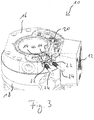
- Fig. 3 shows a similar sectional view as Fig. 2 , but here two connections 22 are additionally shown, each of which is connected to a connection 14 of the vacuum device 10. Starting from a respective connection 22, a line 24 runs to a respective accessory unit, which is not shown here.
- the connections 14 are designed as sockets and the connections 22 as plugs.
- the first exemplary connection diagram shown is provided with two accessory units 26 for connection to a vacuum device 10.
- the vacuum device 10 comprises a control unit 12 with two connections 14 for respective connections 22 of the accessory units 26.
- the connections 22 are each connected to the accessory unit 26 via a line 24, but, for example, it is also conceivable to form the connector 22 directly on the accessory unit 26 .
- An accessory unit 26 could form a plug-in module.
- a connection 14 can also be connected to the control unit 12 or the vacuum device 10 via a line or otherwise, but be made separately.
- a second connection diagram is in Fig. 5 shown.
- a vacuum device 10 comprises a connection 14 provided on the housing of the vacuum device 10, an accessory unit 26 with a connection 22 being provided for connection to the connection 14 arranged on the vacuum device 10.
- a control unit 12 comprises three connections 14.
- a connection 22 is provided for connection to one of the three connections 14 and connects the control unit 12 to an accessory unit 26 which is attached to and / or in the vacuum device 10.
- This Accessory unit 26 can have, for example, a heating element for heating the vacuum device 10 and / or a sensor for detecting a parameter prevailing in or on the vacuum device 10.
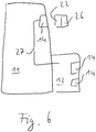
- the third connection diagram shown includes a vacuum device 10, a control unit 12 with two connections 14.
- a further connection 14 is provided on a housing part of the vacuum device 10 separately from the control unit 12.
- the connection 14 is connected to the control unit 12 via a line 27.
- the line 27 runs inside and / or in the housing of the vacuum device 10 or the control unit 12.
- the connection 14 can be used, for example, both for a mechanical connection of the accessory unit 26 with the vacuum device 10 and for an electrical and / or information technology connection of the accessory unit 26 be formed on the control unit 12.
- the control unit 12 can generally be designed as a component that is adjacent to the main housing of the vacuum device 10 and / or can also be integrated, that is to say can also be provided elsewhere in the vacuum device 10.
- connection 22 which is connected directly to the control unit 26. No flexible line is therefore provided. However, such an arrangement can alternatively or additionally be provided. Via the connection 22, the accessory unit 26 is connected to the connection 14 of the vacuum device 10 both mechanically and electrically and / or in terms of information technology.
- FIG. 7 A fourth connection diagram is shown, in which a control unit 12 is arranged integrated in a housing of the vacuum device 10.
- the control unit 12 comprises a connection 14.
- the vacuum device 10 comprises a further connection 14, which is connected to the control unit via a line 27.
- Two connection units (not shown) can be connected to the respective connections 14 via connections 22.
- FIG. 8 A vacuum device 10 with a connection 14 is shown.
- an accessory unit 26 can be connected to the connector 14, which includes a connector 22 for connecting the accessory unit 26 to the connector 14 of the vacuum device 10.
- the accessory unit 26 also includes a connector 14 for connecting one or more additional accessory units.
- An adapter 28, for example, can be connected to one of the connections 14 via a connection 22 and has a plurality of connections 14 for connecting further accessories.
- connection 14 of a vacuum device not shown here, is shown, which has a supply contact 30 and a communication contact 32.
- An accessory unit 26 also has a supply contact 34 and a communication contact 36 at a connection 22.
- the accessory unit 26 can therefore communicate with a control unit via the communication contacts 36 and 32 of the connections 22 and 14, respectively.
- an accessory unit 26 with only one supply contact 34 is shown.
- This accessory unit 26 can be supplied with electrical energy via the supply contacts 34 and 30.
- This accessory unit 26 illustrates an accessory unit of an older generation than the upper accessory unit 26.
- the vacuum device with the connection 14 can advantageously be designed such that the lower accessory unit 26 can also be operated without automatic recognition of its type.
- a communication device and / or a communication contact can, however, also be retrofittable on an accessory unit, for example via a detection unit 38 connected between the connection 22 of the lower accessory unit 26 and the connection 14 of the vacuum device.
- the detection unit 38 has a supply contact 30 at the connection 14 for supply of the accessory unit 26.
- the detection unit 38 can use this, for example, to output a signal which indicates the type of the connected Accessory unit 26 displays. The signal or the type can be preprogrammed and / or can be entered, for example.
Landscapes
- Engineering & Computer Science (AREA)
- Mechanical Engineering (AREA)
- General Engineering & Computer Science (AREA)
- Compressors, Vaccum Pumps And Other Relevant Systems (AREA)
- Non-Positive Displacement Air Blowers (AREA)
Abstract
Description
- Die vorliegende Erfindung betrifft ein Vakuumgerät, insbesondere Vakuumpumpe, mit zumindest einem Anschluss für eine Zubehöreinheit und mit einer Steuereinheit für die Zubehöreinheit.
- Die Erfindung betrifft auch eine Zubehöreinheit für ein Vakuumgerät, insbesondere Vakuumpumpe, mit einem Anschluss zum Anschließen an einen Anschluss des Vakuumgeräts.
- Die Erfindung betrifft auch ein System mit Vakuumgerät und Zubehöreinheit.
- Bei einem beispielhaften Vakuumgerät des Standes der Technik sind ein oder mehrere Anschlüsse jeweils für eine Zubehöreinheit vorgesehen. Die Zubehöreinheit wird nach Anschließen an den Anschluss durch eine Steuereinheit des Vakuumgeräts betrieben.
- Es ist eine Aufgabe der Erfindung, den Anschluss von Zubehör an ein Vakuumgerät zu vereinfachen und/oder flexibler zu gestalten.
- Diese Aufgabe wird durch ein Vakuumgerät mit den Merkmalen des Anspruchs 1 gelöst, und insbesondere dadurch, dass die Steuereinheit dazu ausgebildet ist, eine an den Anschluss angeschlossene Zubehöreinheit in ihrer Art zu erkennen.
- Hierdurch kann das Anschließen der Zubehöreinheit besonders einfach erfolgen, insbesondere ohne händische oder anderweitig externe Konfiguration. Der Betrieb des Vakuumgeräts wird hierdurch auch besonders flexibel, da Zubehöreinheiten ohne großen Aufwand und je nach Bedarf angeschlossen, getrennt und/oder ausgewechselt werden können. Erfindungsgemäß ist also ein besonders komfortabler Betrieb im Sinne eines "Plug-and-Play"-Konzepts realisiert, wie es aus dem entfernten technischen Gebiet der Personal Computer bekannt ist. Eine angeschlossene Zubehöreinheit gewinnt somit aus Sicht des Nutzers in vorteilhafter Weise ihre Funktion schlicht durch Anschließen am Anschluss. Die Steuereinheit kann in Kenntnis der Art der Zubehöreinheit diese bedarfsgerecht ansteuern.
- Der Begriff "Art" erfasst folglich zumindest die Informationen, die zum sicheren Betrieb der Zubehöreinheit nötig sind. Beispielsweise kann die Steuereinheit die Zubehöreinheit anhand eines Kennzeichens erkennen und weitere Informationen, wie etwa maximal erträgliche Spannung, aus einer hinterlegten Tabelle abrufen. Alternativ kann es auch vorgesehen sein, dass die Steuereinheit unmittelbar die nötigen Informationen erkennt, insbesondere anhand eines von der Zubehöreinheit ausgesendeten Signals.
- Gemäß einer Ausführungsform kann der Anschluss wenigstens einen Kommunikationskontakt zur kommunikativen Anbindung der Zubehöreinheit an die Steuereinheit aufweisen. Hierunter ist nicht notwendigerweise ein metallischer und/oder elektrischer Kontakt zu verstehen, sondern allgemein ein Anschlusspunkt für leitungsgebundene Kommunikation. So kann beispielsweise auch ein optischer Kontakt, z.B. für einen Lichtwellenleiter, vorgesehen sein. Alternativ oder zusätzlich kann beispielsweise auch eine vom Anschluss separate, insbesondere drahtlose, Kommunikationsschnittstelle vorgesehen sein. Durch die Möglichkeit zur Kommunikation zwischen Steuereinheit und Zubehöreinheit wird die Erkennung nicht nur vereinfacht, sondern auch der Betrieb erheblich flexibilisiert, da nun zwischen Steuereinheit und Zubehöreinheit Daten ausgetauscht werden können. Insbesondere ist eine Kommunikation in beiden Richtungen möglich. Beispielsweise kann der Kommunikationskontakt auch zur Kommunikation mit anderen Einheiten nutzbar sein, die nicht Zubehöreinheiten sind, also beispielsweise zur Kommunikation mit einer Konfigurations- und/oder Diagnoseeinheit, einem weiteren Vakuumgerät und/oder einem Prozessleitsystem. Mit Vorteil kann dann auf eine gesonderte Schnittstelle, wie etwa eine Diagnose- oder Konfigurationsschnittstelle, verzichtet werden. Grundsätzlich können auch mehrere Kommunikationskontakte, insbesondere je Anschluss, vorgesehen sein.
- Es kann vorgesehen sein, dass der Anschluss wenigstens einen Versorgungskontakt zur elektrischen Versorgung der Zubehöreinheit aufweist. Die Zubehöreinheit benötigt somit keinen zusätzlichen Stromanschluss, was die Anordnung vereinfacht. Für den Versorgungskontakt bzw. für den Anschluss kann beispielsweise ein Treiber vorgesehen sein. Dieser kann vorteilhaft so ausgelegt sein, dass auch Zubehöreinheiten älterer Gerätegenerationen, insbesondere ohne Mittel zum Aussenden von Erkennungssignalen, zuverlässig betreibbar sind.
- Beispielsweise kann die Steuereinheit dazu ausgebildet sein, die Zubehöreinheit, insbesondere über den Versorgungskontakt, mit unterschiedlichen Spannungen zu versorgen. Im einfachsten Fall sind dies zwei unterschiedliche Spannungen, insbesondere Null und eine generelle Betriebsspannung für alle Zubehöreinheiten. Insbesondere vorteilhaft sind wenigstens zwei von Null verschiedene, unterschiedliche Spannungen. Hierdurch kann der Anschluss von Zubehöreinheiten weiter flexibilisiert werden, da diese bedarfsgerecht versorgt werden können, ohne dass ein Transformator an der Zubehöreinheit nötig wäre. Bei einem weiteren Beispiel ist die Steuereinheit dazu ausgebildet, grundsätzlich, insbesondere am Anschluss bzw. am Versorgungskontakt, eine erste von Null verschiedene Spannung, beispielsweise 5 V, anzulegen und nach einer Erkennung und/oder Kommunikation mit der Zubehöreinheit eine andere, für die Zubehöreinheit geeignete Spannung, beispielsweise 24 V, anzulegen.
- Bei einem weiteren Beispiel liegt, z.B. am Versorgungskontakt, dauerhaft eine bestimmte Versorgungsspannung an. Dabei steuert sich die Zubehöreinheit vorteilhafter Weise selbst, insbesondere in Abhängigkeit von durch die Steuereinheit vorgegebenen Befehlen oder Daten, welche vorteilhafter Weise über einen Kommunikationskontakt des Anschlusses übertragen werden. Hierdurch werden Vakuumgerät und Steuereinheit technisch vereinfacht.
- Der Versorgungskontakt kann beispielsweise sowohl zur Energieversorgung der Zubehöreinheit als auch als bloßes Schaltmittel zum Betätigen eines Schalters, wie etwas eines Relais', verwendbar sein. Der Betrieb wird hierdurch weiter flexibilisiert. So können beispielsweise auch Zubehöreinheiten betrieben werden, für die eine Stromversorgung über das Vakuumgerät unmöglich oder technisch sehr aufwendig wäre. Beispielsweise kann es sich bei der Zubehöreinheit um eine Vorpumpe für das hierbei als Vakuumpumpe ausgebildete Vakuumgerät handeln. Diese Vorpumpe benötigt eine relativ große Leistung, die über das Vakuumgerät nur mit besonderem technischen Aufwand bereitzustellen wäre. Dies führt obendrein zu einem vergrößerten Bauraum, was häufig unerwünscht ist. Somit wird bei diesem Beispiel die Energieversorgung der Zubehöreinheit vorteilhaft ausgelagert. Insoweit oben ein Vakuumgerät als eine von der Zubehöreinheit verschiedene Einheit beschrieben wird, bezieht sich dies auf Vakuumgeräte, die nicht als Zubehör für das erfindungsgemäße Vakuumgerät gedacht sind, sondern nebengeordnet betrieben werden. Die hier beschriebene Vorpumpe ist dagegen der Vakuumpumpe untergeordnet und abhängig. Außerdem wird die Vorpumpe in diesem Beispiel über den Versorgungskontakt angesteuert. Grundsätzlich kann sie aber auch über einen Kommunikationskontakt oder andere Kommunikationsmittel angesteuert werden. Es wird deutlich, dass der erfindungsgemäße Anschluss vielfältig ausgestaltet und genutzt werden kann. Eine Ansteuerung und/oder Kommunikation kann für zahlreiche Einheiten, insbesondere ausgehend von der Steuereinheit, realisiert werden. Bei alldem sorgt die erfindungsgemäße selbsttätige Erkennung der Zubehöreinheit durch die Steuereinheit für eine völlig neue Flexibilität und Einfachheit.
- Bei einem weiteren praktischen Beispiel ist die Steuereinheit dazu ausgebildet, die Zubehöreinheit in Abhängigkeit von Parametern des Vakuumgeräts anzusteuern. Z.B. wird bei einer als Lüfter ausgebildeten Zubehöreinheit die Drehzahl in Abhängigkeit von einer Temperatur im oder am Vakuumgerät gesteuert. Diese Ansteuerung kann einerseits über einen Versorgungskontakt erfolgen und andererseits über einen Kommunikationskontakt, wobei dann die Zubehöreinheit dazu veranlasst wird, die Drehzahl selbst anzupassen. Bei einem im Hinblick auf Abwärtskompatibilität besonders vorteilhaften Beispiel sind Vakuumgerät und/oder Zubehöreinheit sogar so ausgestaltet, dass beides möglich ist.
- Grundsätzlich kann auch ein gemeinsamer Kontakt als Kommunikationskontakt und Versorgungskontakt vorgesehen sein. Die Kommunikation und die Versorgung sind dann auch über dieselbe Leitung möglich. Dies erweist sich insbesondere im Hinblick auf die Kompatibilität als vorteilhaft. So brauchen bestehende Anschlüsse nicht umkonstruiert werden. Außerdem ist und bleibt die Konstruktion einfach.
- Gemäß einer Weiterbildung ist vorgesehen, dass die Steuereinheit dazu ausgebildet ist, aus einem von der Zubehöreinheit ausgehenden Signal die Art der Zubehöreinheit zu erkennen. Hierdurch kann eine besonders einfache und zuverlässige Erkennung verwirklicht werden. Das Signal kann beispielsweise ein Kennzeichen und/oder Informationen umfassen, die unmittelbar Parameter der Zubehöreinheit, wie etwa Betriebsspannung, betreffen.
- Das Signal kann beispielsweise über einen Kommunikationskontakt des Anschlusses der Steuereinheit zur Verfügung gestellt werden. Dies ermöglicht einen besonders einfachen Betrieb. Alternativ oder zusätzlich kann das Signal auch unabhängig vom Anschluss, insbesondere über einen zusätzlichen Anschluss und/oder drahtlos, zur Verfügung gestellt werden.
- Am Anschluss kann bei einem Ausführungsbeispiel eine serielle Schnittstelle für die Zubehöreinheit vorgesehen sein. Hierdurch kann auf einfache Weise eine besonders zuverlässige Kommunikation realisiert werden.
- Alternativ oder zusätzlich kann am Anschluss eine Busschnittstelle für die Zubehöreinheit vorgesehen sein. Dies ermöglicht einen besonders flexiblen Betrieb für eine Vielzahl von Zubehöreinheiten.
- Grundsätzlich können bei mehreren Anschlüssen die Zubehöreinheiten einzeln und/oder in Gruppen ansteuerbar sein. Insbesondere kann die Zahl der Zubehöreinheiten erweiterbar sein.
- Bei mehreren Anschlüssen kann die Steuereinheit eine Zuordnung der angeschlossenen Zubehöreinheiten zum jeweiligen Anschluss beispielsweise über eine Topologie erkennen, also über eine direkte oder zugeordnete Einzelverdrahtung zwischen Steuereinheit und den jeweiligen Anschlüssen. Alternativ kann aber auch beispielsweise eine Zuordnung über ein Bussystem erfolgen.
- Bei einem Ausführungsbeispiel ist die Steuereinheit dazu ausgebildet, von der Zubehöreinheit zur Verfügung gestellte Nutzdaten zu verarbeiten. Als Nutzdaten werden hierbei solche Daten betrachtet, die von Erkennungsdaten verschieden sind. Beispielsweise umfassen Nutzdaten Sensordaten. So kann die Zubehöreinheit beispielsweise einen Sensor umfassen und dessen Informationen entweder analog oder digital, insbesondere über den Anschluss, zur Verfügung stellen. Es ist dabei mit Kostenvorteil möglich, auf einen für den Sensor vorgesehenen separaten Konverter zu verzichten. So wird nicht nur ein Konverter eingespart, sondern allgemein erhältliche Zulieferteile sind auch ohne große technische Anpassung mit der Steuereinheit betreibbar.
- Bei einer Weiterbildung ist vorgesehen, dass die Steuereinheit dazu ausgebildet ist, die Zubehöreinheit zu betreiben, selbst wenn die Steuereinheit die Zubehöreinheit nicht in ihrer Art erkennt. Für diesen Fall kann beispielsweise eine Eingabeeinheit zur Eingabe der Art der Zubehöreinheit an die Steuereinheit vorgesehen sein. Eine Eingabe kann grundsätzlich auch über einen zusätzlichen Anschluss für eine Zubehöreinheit erfolgen, wobei an diesem Anschluss als Zubehöreinheit entweder selbst eine Eingabeeinheit oder eine Kommunikationseinheit zum Empfang von einer Eingabeeinheit angeschlossen oder anschließbar sein kann.
- Weiterhin kann die Steuereinheit dazu ausgebildet sein, mehr als eine am Anschluss angeschlossene Zubehöreinheit gleichzeitig zu betreiben. So kann beispielsweise zumindest eine unmittelbar am Anschluss angeschlossene oder anschließbare Zubehöreinheit wenigstens einen zusätzlichen Anschluss zum Anschließen wenigstens einer zusätzlichen Zubehöreinheit aufweisen. Hierdurch ist eine Verkettung von Zubehöreinheiten realisiert und es bleibt ohne zusätzliche Adapter und bei gleichbleibender Zahl von Anschlüssen am Vakuumgerät die Möglichkeit zum Anschließen, insbesondere zahlreicher, weiterer Zubehöreinheiten erhalten. Grundsätzlich kann der zusätzliche Anschluss entweder direkt mit dem ersten Anschluss der Zubehöreinheit verbunden sein, oder aber über eine Verarbeitungseinheit, beispielsweise einen Mikroprozessor verbunden sein, wobei beispielsweise über die Weiterleitung von Daten und/oder Spannung von einer vorrangig angeschlossenen Zubehöreinheit für eine oder mehrere nachfolgende Zubehöreinheiten entschieden werden kann. Alternativ oder zusätzlich kann aber auch ein Adapter zum parallelen Anschluss von wenigstens zwei Zubehöreinheiten an einen Anschluss vorgesehen sein. Für den Fall, dass mehrere gleichartige Zubehöreinheiten an einem Anschluss des Vakuumgeräts angeschlossen sind, kann beispielsweise eine Erkennung und/oder Zuordnung über Adresswahlschalter oder vorprogrammierte Adressen erfolgen. Grundsätzlich kann auch eine Zubehöreinheit über mehrere Anschlüsse anschließbar sein, beispielsweise um eine größere Leistung, insbesondere an den Versorgungskontakten, und/oder eine größere Kommunikationsdatenrate, insbesondere an einem Kommunikationskontakt, zu realisieren.
- Grundsätzlich kann die Steuereinheit eine Motorsteuerung für das Vakuumgerät, insbesondere Vakuumpumpe, umfassen oder Teil einer solchen sein. Es ist aber auch möglich, dass die Steuereinheit separat von einer Motorsteuerung und/oder separat von anderen Steuerungselementen ausgeführt ist. Es können eine oder mehrere separate Steuereinheiten jeweils für einen oder mehrere Anschlüsse vorgesehen werden. Beispielsweise kann eine Steuereinheit für einen Anschluss, und insbesondere benachbart zu oder integriert in diesen, vorgesehen sein. Hierbei ist vorteilhaft, dass die Steuereinheit, insbesondere über den Anschluss, auch kontaktiert und ausgelesen werden kann, wenn die Motorsteuerung oder das andere Steuerungselement nicht angebracht ist. Dies führt zu einer weiteren Flexibilisierung des Betriebs und der Wartung des Vakuumgeräts bzw. eines Vakuumsystems.
- Ein Anschluss kann beispielsweise männlich oder weiblich ausgebildet sein und/oder einen Stecker oder eine Buchse umfassen, wobei auch andere Anschlussarten denkbar sind.
- Die Aufgabe der Erfindung wird auch durch eine Zubehöreinheit mit den Merkmalen des hierauf gerichteten unabhängigen Anspruchs gelöst, und insbesondere dadurch, dass die Zubehöreinheit dazu ausgebildet ist, insbesondere über den Anschluss, insbesondere über einen Kommunikationskontakt, ein Signal auszugeben, anhand dessen die Zubehöreinheit in ihrer Art erkennbar ist.
- Die Zubehöreinheit kann beispielsweise ein Heizelement, einen Lüfter, ein Flutventil, ein Sperrgasventil, ein Steuerrelais, beispielsweise für eine Vorpumpe, ein Druckmessgerät und/oder eine, insbesondere integrierte, Messröhre umfassen. Allgemeiner kann also die Zubehöreinheit beispielsweise wenigstens einen Aktor und/oder Sensor umfassen. Es sind aber auch Zubehöreinheiten mit anderen Funktionselementen denkbar. So kann beispielsweise auch eine Zubehöreinheit ein Speicherelement zum Speichern von Daten umfassen. Hiermit kann beispielsweise eine Datenaufzeichnung von Pumpendaten über einen längeren Zeitraum realisiert werden.
- Bei einem vorteilhaften Ausführungsbeispiel umfasst die Zubehöreinheit sowohl einen Aktor als auch einen Sensor, insbesondere für einen vom Aktor beeinflussbaren Parameter. Die Zubehöreinheit ist dabei insbesondere und dazu ausgebildet ist, Daten, insbesondere Nutzdaten, von dem Sensor über den Anschluss auszugeben. Beispiele für von Aktoren beeinflussbare Parameter sind eine Temperatur an einem Heizelement und eine Drehzahl an einem Lüfter. Die Sensordaten können vorteilhaft für eine Funktionsüberprüfung des Aktors oder auch zu dessen Ansteuerung in Abhängigkeit der Sensordaten genutzt werden.
- Die Zubehöreinheit kann beispielsweise auch alternativ oder zusätzlich selbst eine Schnittstelle zur Kommunikation mit weiteren Geräten oder Einheiten aufweisen. Beispielsweise umfasst die Zubehöreinheit eine Drahtlosschnittstelle. Sie kann dabei beispielsweise ein Funkmodul bilden, mittels dessen insbesondere flexibel eine Drahtlosverbindung an einem Vakuumgerät nachgerüstet werden kann. Die Drahtlosschnittstelle kann beispielsweise entsprechend zumindest einem der Standards für GSM, UMTS, LTE und/oder anderer Mobilfunkstandards, Bluetooth, NFC und/oder WLAN ausgebildet sein. Insbesondere kann die Zubehöreinheit auf diese Weise ein oder mehrere beliebige andere Geräte, die z.B. selbst eine Zubehörheinheit für ein, insbesondere erfindungsgemäßes, Vakuumgerät darstellen, per Funk - allgemein also drahtlos - auslesen, steuern, erkennen etc.
- Die Zubehöreinheit kann mit Vorteil dazu ausgebildet sein, auch dann von einer Steuereinheit des Vakuumgeräts betreibbar zu sein, wenn diese die Zubehöreinheit nicht in ihrer Art erkennt, beispielsweise weil das Vakuumgerät keine Erkennungsmittel aufweist. Dies ermöglicht eine vorteilhafte Abwärtskompatibilität, also einen Betrieb an einem älteren Vakuumgerät. Hierfür kann die Zubehöreinheit beispielsweise dazu ausgebildet sein, die Tatsache der Nichterkennung selbst zu erkennen, beispielsweise durch den missglückenden Versuch, eine Kommunikation mit der Steuereinheit, insbesondere über einen Kommunikationskontakt des Anschlusses, aufzubauen.
- Bei einer Ausführungsform ist vorgesehen, dass die Zubehöreinheit wenigstens einen zweiten Anschluss zum Anschließen einer weiteren Zubehöreinheit an die Zubehöreinheit und/oder an das Vakuumgerät aufweist. Der zweite Anschluss und dessen Kontakte können direkt mir dem ersten Anschluss verbunden sein, wobei insbesondere die Kontakte und die Zubehöreinheit zum Anschluss an ein Bussystem ausgebildet sein können. Alternativ kann auch eine Verarbeitungseinheit der Zubehöreinheit zwischen die Anschlüsse geschaltet sein. Dabei kann die Zubehöreinheit beispielsweise die Informationen und/oder Spannungen an der Weiterleitung hindern und/oder diese ändern.
- Der Anschluss des Vakuumgeräts und/oder der Zubehöreinheit kann beispielsweise sowohl für eine mechanische Verbindung als auch für eine elektrische und/oder informationstechnische Anbindung der Zubehöreinheit an die Steuereinheit ausgebildet sein. Dies ermöglicht ein besonders flexibles Anschließen.
- Die Aufgabe wird auch gelöst durch eine Erkennungseinheit mit den Merkmalen des hierauf gerichteten, unabhängigen Anspruchs. Die Erkennungseinheit kann beispielsweise vorteilhaft zur Nachrüstung einer älteren Zubehöreinheit verwendet werden. Das Signal kann insbesondere über den ersten Anschluss, insbesondere über einen Kommunikationskontakt, ausgegeben werden. Die Erkennungseinheit kann zum Beispiel eine Eingabeeinheit zur Eingabe einer Art einer Zubehöreinheit und/oder eine vorprogrammierte Art zur Ausgabe im Signal aufweisen.
- Die Aufgabe der Erfindung wird auch durch ein System gelöst, welches ein erfindungsgemäßes Vakuumgerät und eine erfindungsgemäße Zubehöreinheit und/oder eine erfindungsgemäße Erkennungseinheit umfasst.
- Ferner wird die Aufgabe durch ein gegenwärtig nicht ausdrücklich beanspruchtes, aber hiermit gesondert als Erfindung offenbartes Verfahren zum Betrieb eines Vakuumgeräts mit einer Zubehöreinheit gelöst, bei dem eine Steuereinheit des Vakuumgeräts eine an einem Anschluss angeschlossene Zubehöreinheit in ihrer Art erkennt.
- Die hierin beschriebenen Aspekte der Erfindung, also Vakuumgerät, Zubehöreinheit, Erkennungseinheit, System und Verfahren lassen sich selbstverständlich und vorteilhaft im Sinne aller zu jeweils anderen Aspekten beschriebenen Ausführungsformen weiterbilden.
- Die Erfindung wird nachfolgend lediglich beispielhaft anhand der schematischen Zeichnung erläutert.
- Fig. 1
- zeigt ein erfindungsgemäßes Vakuumgerät in perspektivischer Ansicht.
- Fig. 2
- zeigt eine Schnittdarstellung des Vakuumgeräts der
Fig. 1 . - Fig. 3
- zeigt eine weitere Schnittdarstellung des Vakuumgeräts der
Fig. 1 , wobei an dem Vakuumgerät zwei Zubehöreinheiten angeschlossen sind. - Fig. 4
- zeigt ein erstes Anschlussschema mit einem Vakuumgerät und Zubehöreinheiten.
- Fig. 5
- zeigt ein zweites Anschlussschema mit Vakuumgerät und Zubehöreinheiten.
- Fig. 6
- zeigt ein drittes Anschlussschema.
- Fig. 7
- zeigt ein viertes Anschlussschema.
- Fig. 8
- zeigt verschiedene Möglichkeiten zum Anschluss mehrerer Zubehöreinheiten an einen Anschluss eines Vakuumgeräts.
- Fig. 9
- zeigt verschiedene Anschlüsse.
- In
Fig. 1 ist ein als Turbomolekularpumpe ausgebildetes Vakuumgerät 10 mit einer Steuereinheit 12 sowie zwei Anschlüssen 14 für Zubehöreinheiten (nicht dargestellt) gezeigt. An die Anschlüsse 14 sind jeweils verschiedene Zubehöreinheiten, wie zum Beispiel Halteelemente, Lüfter, Flutventile, Sperrgasventile, Steuerrelais, Druckmessgeräte und/oder integrierte Messröhren, anschließbar. Es können ein, wie hier zwei oder mehrere Anschlüsse 14 vorgesehen sein. Die Anschlüsse 14 sind in diesem Beispiel an einem Unterteil 16 eines Gehäuses des Vakuumgeräts angeordnet. Ein oder mehrere Anschlüsse 14 können aber auch andernorts, zum Beispiel an einem Oberteil 18 des Gehäuses und/oder an und/oder in der Steuereinheit 12 bzw. dessen Gehäuse angeordnet sein. - Bei der in
Fig. 2 gezeigten Schnittdarstellung des Vakuumgeräts 10 derFig. 1 verläuft die Schnittebene im Wesentlichen durch das Unterteil 16, wobei das Vakuumgerät 10 im Wesentlichen um 180° gedreht ist, das Vakuumgerät also von unten betrachtet wird. Es ist eine Elektronik 20 sichtbar, die selbst, alternativ oder zusätzlich zur Steuereinheit 12, eine Steuereinheit für an die Anschlüsse 14 angeschlossene Zubehöreinheiten bilden kann. Die Steuereinheit 12 kann beispielsweise eine Motorsteuerung umfassen. Die Elektronik 20 kann als Steuereinheit für ein oder mehrere Zubehöreinheiten beispielsweise derart ausgestaltet sein, dass ein Betrieb der Zubehöreinheit auch dann möglich ist, wenn die Steuereinheit 12 nicht angeschlossen ist. -
Fig. 3 zeigt eine ähnliche Schnittdarstellung wieFig. 2 , wobei hier jedoch zusätzlich zwei Anschlüsse 22 gezeigt sind, welche jeweils an einen Anschluss 14 des Vakuumgeräts 10 angeschlossen sind. Ausgehend von einem jeweiligen Anschluss 22 verläuft eine Leitung 24 zu einer jeweiligen Zubehöreinheit, die hier nicht dargestellt ist. In dieser Ausführungsform sind die Anschlüsse 14 als Buchsen und die Anschlüsse 22 als Stecker ausgebildet. - Bei dem in
Fig. 4 gezeigten, ersten beispielhaften Anschlussschema sind zwei Zubehöreinheiten 26 zum Anschluss an ein Vakuumgerät 10 vorgesehen. Das Vakuumgerät 10 umfasst eine Steuereinheit 12 mit zwei Anschlüssen 14 für jeweilige Anschlüsse 22 der Zubehöreinheiten 26. Die Anschlüsse 22 sind jeweils mit der Zubehöreinheit 26 über eine Leitung 24 verbunden, wobei beispielsweise aber auch eine Ausbildung des Anschlusses 22 unmittelbar an der Zubehöreinheit 26 denkbar ist. Eine Zubehöreinheit 26 könnte dabei ein Steckmodul bilden. Grundsätzlich kann auch ein Anschluss 14 mit der Steuereinheit 12 oder dem Vakuumgerät 10 über eine Leitung oder anderweitig verbunden, aber separat ausgeführt sein. - Ein zweites Anschlussschema ist in
Fig. 5 gezeigt. Ein Vakuumgerät 10 umfasst einen am Gehäuse des Vakuumgeräts 10 vorgesehenen Anschluss 14, wobei eine Zubehöreinheit 26 mit einem Anschluss 22 zum Anschluss an den am Vakuumgerät 10 angeordneten Anschluss 14 vorgesehen ist. Eine Steuereinheit 12 umfasst drei Anschlüsse 14. Ein Anschluss 22 ist zum Anschließen an einen der drei Anschlüsse 14 vorgesehen und verbindet die Steuereinheit 12 mit einer Zubehöreinheit 26, welche an und/oder in dem Vakuumgerät 10 angebracht ist. Diese Zubehöreinheit 26 kann beispielsweise ein Heizelement zum Heizen des Vakuumgeräts 10 und/oder einen Sensor zum Erfassen eines in oder an dem Vakuumgerät 10 herrschenden Parameters aufweisen. - Bei dem in
Fig. 6 gezeigten, dritten Anschlussschema umfasst ein Vakuumgerät 10 eine Steuereinheit 12 mit zwei Anschlüssen 14. Ein weiterer Anschluss 14 ist an einem Gehäuseteil des Vakuumgeräts 10 separat von der Steuereinheit 12 vorgesehen. Über eine Leitung 27 ist der Anschluss 14 mit der Steuereinheit 12 verbunden. Die Leitung 27 verläuft im Inneren und/oder im Gehäuse des Vakuumgeräts 10 bzw. der Steuereinheit 12. Der Anschluss 14 kann beispielsweise sowohl für eine mechanische Verbindung der Zubehöreinheit 26 mit dem Vakuumgerät 10 als auch für eine elektrische und/oder informationstechnische Anbindung der Zubehöreinheit 26 an die Steuereinheit 12 ausgebildet sein. Die Steuereinheit 12 kann ganz generell wie dargestellt als ein dem Hauptgehäuse des Vakuumgeräts 10 nebengeordnetes Bauteil und/oder auch integriert ausgebildet sein, also auch andernorts im Vakuumgerät 10 vorgesehen sein. Auch Zahl und Anordnung von weiteren Anschlüssen 14 können variieren. Die Zubehöreinheit 26 weist einen Anschluss 22 auf, der unmittelbar mit der Steuereinheit 26 verbunden ist. Es ist also keine flexible Leitung vorgesehen. Eine solche kann aber alternativ oder zusätzlich vorgesehen sein. Über den Anschluss 22 wird die Zubehöreinheit 26 sowohl mechanisch als auch elektrisch und/oder informationstechnisch an den Anschluss 14 des Vakuumgeräts 10 angeschlossen. - In
Fig. 7 ist ein viertes Anschlussschema gezeigt, bei dem eine Steuereinheit 12 in einem Gehäuse des Vakuumgeräts 10 integriert angeordnet ist. Die Steuereinheit 12 umfasst einen Anschluss 14. Das Vakuumgerät 10 umfasst einen weiteren Anschluss 14, der mit der Steuereinheit über eine Leitung 27 verbunden ist. Über Anschlüsse 22 sind zwei nicht dargestellte Zubehöreinheiten an die jeweiligen Anschlüsse 14 anschließbar. - In
Fig. 8 ist ein Vakuumgerät 10 mit einem Anschluss 14 gezeigt. An den Anschluss 14 ist beispielsweise eine Zubehöreinheit 26 anschließbar, welche einen Anschluss 22 zum Anschluss der Zubehöreinheit 26 an den Anschluss 14 des Vakuumgeräts 10 umfasst. Die Zubehöreinheit 26 umfasst außerdem einen Anschluss 14 zum Anschließen einer oder mehrerer weiterer Zubehöreinheiten. An einem der Anschlüsse 14 kann über einen Anschluss 22 beispielsweise ein Adapter 28 anschließbar sein, der eine Mehrzahl an Anschlüssen 14 zum Anschließen weiterer Zubehöreinheiten aufweist. - In
Fig. 9 ist ein Anschluss 14 eines hier nicht näher dargestellten Vakuumgeräts gezeigt, der einen Versorgungskontakt 30 sowie einen Kommunikationskontakt 32 aufweist. Eine Zubehöreinheit 26 weist an einem Anschluss 22 ebenfalls einen Versorgungskontakt 34 sowie einen Kommunikationskontakt 36 auf. Die Zubehöreinheit 26 kann also über die Kommunikationskontakte 36 und 32 der Anschlüsse 22 bzw. 14 mit einer Steuereinheit kommunizieren. Dagegen ist unten inFig. 9 eine Zubehöreinheit 26 mit lediglich einem Versorgungskontakt 34 gezeigt. Diese Zubehöreinheit 26 ist über die Versorgungskontakte 34 und 30 mit elektrischer Energie versorgbar. Diese Zubehöreinheit 26 illustriert eine Zubehöreinheit einer gegenüber der oberen Zubehöreinheit 26 älteren Generation. Das Vakuumgerät mit dem Anschluss 14 kann vorteilhaft so ausgebildet sein, dass die untere Zubehöreinheit 26 auch ohne selbsttätige Erkennung ihrer Art betreibbar ist. Eine Kommunikationseinrichtung und/oder ein Kommunikationskontakt können an einer Zubehöreinheit aber beispielsweise auch nachrüstbar sein, beispielsweise über eine zwischen den Anschluss 22 der unteren Zubehöreinheit 26 und den Anschluss 14 des Vakuumgeräts geschaltete Erkennungseinheit 38. Die Erkennungseinheit 38 weist am Anschluss 14 einen Versorgungskontakt 30 zum Versorgen der Zubehöreinheit 26 auf. Am Anschluss 22 weist sie zusätzlich zum Versorgungskontakt 34 einen Kommunikationskontakt 36 auf. Hierüber kann die Erkennungseinheit 38 beispielsweise ein Signal ausgeben, welches die Art der angeschlossenen Zubehöreinheit 26 anzeigt. Das Signal bzw. die Art kann beispielsweise vorprogrammiert und/oder eingebbar sein. - Insbesondere kann unabhängig von der Art und dem Inhalt des jeweiligen Signals dieses per Funk - allgemein also drahtlos - ausgegeben werden.
-
- 10
- Vakuumgerät
- 12
- Steuereinheit
- 14
- Anschluss
- 16
- Unterteil
- 18
- Oberteil
- 20
- Elektronik
- 22
- Anschluss
- 24
- Leitung
- 26
- Zubehöreinheit
- 27
- Leitung
- 28
- Adapter
- 30
- Versorgungskontakt
- 32
- Kommunikationskontakt
- 34
- Versorgungskontakt
- 36
- Kommunikationskontakt
- 38
- Erkennungseinheit
Claims (15)
- Vakuumgerät (10), insbesondere Vakuumpumpe,
mit zumindest einem Anschluss (14) für eine Zubehöreinheit (26) und mit einer Steuereinheit (12) für die Zubehöreinheit (26),
wobei die Steuereinheit (12) dazu ausgebildet ist, eine an den Anschluss (14) angeschlossene Zubehöreinheit (26) in ihrer Art zu erkennen. - Vakuumgerät (10) nach Anspruch 1,
dadurch gekennzeichnet,
dass der Anschluss (14) wenigstens einen Kommunikationskontakt (32) zur kommunikativen Anbindung der Zubehöreinheit (26) an die Steuereinheit (12) aufweist. - Vakuumgerät (10) nach Anspruch 1 oder 2,
dadurch gekennzeichnet,
dass der Anschluss (14) wenigstens einen Versorgungskontakt (30) zur elektrischen Versorgung der Zubehöreinheit (26) aufweist. - Vakuumgerät (10) nach zumindest einem der vorstehenden Ansprüche,
dadurch gekennzeichnet,
dass die Steuereinheit (12) dazu ausgebildet ist, die Zubehöreinheit (26) mit unterschiedlichen Spannungen zu versorgen. - Vakuumgerät (10) nach zumindest einem der vorstehenden Ansprüche,
dadurch gekennzeichnet,
dass die Steuereinheit (12) dazu ausgebildet ist, aus einem von der Zubehöreinheit (26) ausgehenden Signal die Art der Zubehöreinheit (26) zu erkennen. - Vakuumgerät (10) nach Anspruch 5,
dadurch gekennzeichnet,
dass das Signal über einen Kommunikationskontakt (32) des Anschlusses (14) der Steuereinheit (12) zur Verfügung gestellt wird. - Vakuumgerät (10) nach zumindest einem der vorstehenden Ansprüche,
dadurch gekennzeichnet,
dass am Anschluss (14) eine serielle Schnittstelle und/oder eine Busschnittstelle für die Zubehöreinheit (26) vorgesehen ist. - Vakuumgerät (10) nach zumindest einem der vorstehenden Ansprüche,
dadurch gekennzeichnet,
dass die Steuereinheit (12) dazu ausgebildet ist, von der Zubehöreinheit (26) zur Verfügung gestellte Nutzdaten zu verarbeiten. - Vakuumgerät (10) nach zumindest einem der vorstehenden Ansprüche,
dadurch gekennzeichnet,
dass die Steuereinheit (12) dazu ausgebildet ist, die Zubehöreinheit (26) zu betreiben, selbst wenn die Steuereinheit (12) die Zubehöreinheit (26) nicht in ihrer Art erkennt. - Vakuumgerät (10) nach zumindest einem der vorstehenden Ansprüche,
dadurch gekennzeichnet,
dass die Steuereinheit (12) dazu ausgebildet ist, mehr als eine am Anschluss (14) angeschlossene Zubehöreinheit (26) gleichzeitig zu betreiben. - Zubehöreinheit (26) für ein Vakuumgerät (10), insbesondere Vakuumpumpe, mit einem Anschluss (22) zum Anschließen an einen Anschluss (14) des Vakuumgeräts (10), wobei die Zubehöreinheit (26) dazu ausgebildet ist, ein Signal auszugeben, anhand dessen die Zubehöreinheit (26) in ihrer Art erkennbar ist.
- Zubehöreinheit (26) nach Anspruch 11,
dadurch gekennzeichnet,
dass die Zubehöreinheit (26) sowohl einen Aktor als auch einen Sensor für einen vom Aktor beeinflussbaren Parameter aufweist und dazu ausgebildet ist, Daten von dem Sensor über den Anschluss (22) auszugeben. - Zubehöreinheit (26) nach Anspruch 12 oder 13,
dadurch gekennzeichnet,
dass die Zubehöreinheit (26) wenigstens einen zweiten Anschluss (14) zum Anschließen einer weiteren Zubehöreinheit (26) an die Zubehöreinheit (26) und/oder an das Vakuumgerät (10) aufweist. - Erkennungseinheit mit einem ersten Anschluss (22) zum Anschließen an einen Anschluss eines Vakuumgeräts (10) und mit einem zweiten Anschluss (14) zum Anschließen einer Zubehöreinheit (26) für das Vakuumgerät (10), wobei die Erkennungseinheit dazu ausgebildet ist, ein Signal auszugeben, anhand dessen eine am zweiten Anschluss (14) angeschlossene oder anschließbare Zubehöreinheit (26) in ihrer Art erkennbar ist
- System umfassend ein Vakuumgerät (10) nach einem der Ansprüche 1 bis 10 und eine Zubehöreinheit (26) nach einem der Ansprüche 11 bis 13 und/oder eine Erkennungseinheit nach Anspruch 14.
Priority Applications (2)
| Application Number | Priority Date | Filing Date | Title |
|---|---|---|---|
| EP18191876.4A EP3617520B1 (de) | 2018-08-31 | 2018-08-31 | Vakuumgerät, zubehöreinheit und system |
| JP2019148482A JP2020056397A (ja) | 2018-08-31 | 2019-08-13 | 真空装置、アクセサリーユニットおよびシステム |
Applications Claiming Priority (1)
| Application Number | Priority Date | Filing Date | Title |
|---|---|---|---|
| EP18191876.4A EP3617520B1 (de) | 2018-08-31 | 2018-08-31 | Vakuumgerät, zubehöreinheit und system |
Publications (2)
| Publication Number | Publication Date |
|---|---|
| EP3617520A1 true EP3617520A1 (de) | 2020-03-04 |
| EP3617520B1 EP3617520B1 (de) | 2021-05-26 |
Family
ID=63452480
Family Applications (1)
| Application Number | Title | Priority Date | Filing Date |
|---|---|---|---|
| EP18191876.4A Active EP3617520B1 (de) | 2018-08-31 | 2018-08-31 | Vakuumgerät, zubehöreinheit und system |
Country Status (2)
| Country | Link |
|---|---|
| EP (1) | EP3617520B1 (de) |
| JP (1) | JP2020056397A (de) |
Cited By (2)
| Publication number | Priority date | Publication date | Assignee | Title |
|---|---|---|---|---|
| ES2874703A1 (es) * | 2020-05-04 | 2021-11-05 | Cecotec Res And Development | Sistema de deteccion de accesorios para electrodomestico |
| EP4027043A1 (de) * | 2021-12-23 | 2022-07-13 | Pfeiffer Vacuum Technology AG | Vakuumventil |
Citations (5)
| Publication number | Priority date | Publication date | Assignee | Title |
|---|---|---|---|---|
| JP2002021851A (ja) * | 2000-07-04 | 2002-01-23 | Koyo Seiko Co Ltd | 磁気軸受制御装置 |
| WO2007115633A1 (de) * | 2006-03-31 | 2007-10-18 | J. Schmalz Gmbh | Unterdruckhandhabungseinrichtung |
| DE202012006795U1 (de) * | 2012-07-13 | 2013-10-14 | Oerlikon Leybold Vacuum Gmbh | Vakuumpumpe sowie Vakuumpumpen-Anlage |
| DE102014206308A1 (de) * | 2014-04-02 | 2015-10-08 | J. Schmalz Gmbh | Handhabungsanlage und Verfahren zum Betreiben einer Handhabungsanlage |
| EP3020975A1 (de) * | 2014-11-12 | 2016-05-18 | Pfeiffer Vacuum Gmbh | Vakuumgerät |
Family Cites Families (10)
| Publication number | Priority date | Publication date | Assignee | Title |
|---|---|---|---|---|
| JPH0599669A (ja) * | 1991-10-04 | 1993-04-23 | Fuji Electric Co Ltd | 変位計 |
| JP3130890B2 (ja) * | 1999-02-25 | 2001-01-31 | セイコー精機株式会社 | 磁気軸受装置及び磁気軸受制御装置 |
| JP3442700B2 (ja) * | 1999-10-15 | 2003-09-02 | Smc株式会社 | 圧力センサ用制御装置および圧力センサシステム |
| JP4919702B2 (ja) * | 2006-05-23 | 2012-04-18 | 株式会社キーエンス | センサ装置及びセンサシステム |
| JP5065703B2 (ja) * | 2007-02-15 | 2012-11-07 | 株式会社荏原製作所 | 回転機械装置における回転機械本体の機種識別方法、回転機械装置 |
| JP4897400B2 (ja) * | 2006-08-31 | 2012-03-14 | 船井電機株式会社 | スキャナ |
| JP4947493B2 (ja) * | 2007-10-09 | 2012-06-06 | 株式会社デンソー | センサ識別機能付き車両用エアコン制御装置 |
| DE102008019451A1 (de) * | 2008-04-17 | 2009-10-22 | Oerlikon Leybold Vacuum Gmbh | Vakuumpumpe |
| JP6690213B2 (ja) * | 2015-12-09 | 2020-04-28 | セイコーエプソン株式会社 | ロボット、制御装置およびロボットシステム |
| JP6625233B2 (ja) * | 2016-10-03 | 2019-12-25 | 三菱電機株式会社 | コントローラ、空気調和システムおよび空気調和機の制御方法 |
-
2018
- 2018-08-31 EP EP18191876.4A patent/EP3617520B1/de active Active
-
2019
- 2019-08-13 JP JP2019148482A patent/JP2020056397A/ja active Pending
Patent Citations (5)
| Publication number | Priority date | Publication date | Assignee | Title |
|---|---|---|---|---|
| JP2002021851A (ja) * | 2000-07-04 | 2002-01-23 | Koyo Seiko Co Ltd | 磁気軸受制御装置 |
| WO2007115633A1 (de) * | 2006-03-31 | 2007-10-18 | J. Schmalz Gmbh | Unterdruckhandhabungseinrichtung |
| DE202012006795U1 (de) * | 2012-07-13 | 2013-10-14 | Oerlikon Leybold Vacuum Gmbh | Vakuumpumpe sowie Vakuumpumpen-Anlage |
| DE102014206308A1 (de) * | 2014-04-02 | 2015-10-08 | J. Schmalz Gmbh | Handhabungsanlage und Verfahren zum Betreiben einer Handhabungsanlage |
| EP3020975A1 (de) * | 2014-11-12 | 2016-05-18 | Pfeiffer Vacuum Gmbh | Vakuumgerät |
Cited By (2)
| Publication number | Priority date | Publication date | Assignee | Title |
|---|---|---|---|---|
| ES2874703A1 (es) * | 2020-05-04 | 2021-11-05 | Cecotec Res And Development | Sistema de deteccion de accesorios para electrodomestico |
| EP4027043A1 (de) * | 2021-12-23 | 2022-07-13 | Pfeiffer Vacuum Technology AG | Vakuumventil |
Also Published As
| Publication number | Publication date |
|---|---|
| JP2020056397A (ja) | 2020-04-09 |
| EP3617520B1 (de) | 2021-05-26 |
Similar Documents
| Publication | Publication Date | Title |
|---|---|---|
| EP1174781B1 (de) | Einrichtung zur Signalübertragung | |
| EP1840682B1 (de) | Elektrisches Feldgerät und Erweiterungsmodul zum Einstecken in das elektrisches Feldgerät | |
| EP3262907B1 (de) | Modulare feldgeräteanschlusseinheit | |
| EP1258957B1 (de) | Schaltgerätesystem | |
| WO1996031815A1 (de) | Einrichtung zur eigensicheren signalanpassung | |
| DE102012001615A1 (de) | Modulanordnung | |
| DE102019127195A1 (de) | Modulares Interfacesystem zum Anschließen einer Steuerungseinrichtung und von Feldgeräte | |
| EP2434355A1 (de) | Not-Aus-Modul-Anordnung | |
| EP3617520B1 (de) | Vakuumgerät, zubehöreinheit und system | |
| EP3647600B1 (de) | Erkennung eines elektrisch angeschlossenen zubehörs | |
| WO2010031414A1 (de) | Funktionsmodul und koppelmodul für eine schaltgerätesteuerung udnsystem zur schaltgerätesteuerung | |
| DE19736581C2 (de) | Feldbusanordnung | |
| EP3028385B1 (de) | Anordnung zum anschluss einer komponente an ein master- steuergerät eines kraftfahrzeugs | |
| WO2018108420A1 (de) | Stellantrieb mit einer usb-schnittstelle | |
| DE212012000249U1 (de) | Vorrichtung zum eigensicheren Versorgen, Ansteuern und/oder Auswerten von Feldgeräten im explosionsgeschützten Bereich | |
| EP3029327B1 (de) | System aus Vakuumgerät und Funktionseinheit | |
| EP3888116B1 (de) | Modulare schaltvorrichtung zum ansteuern wenigstens eines elektrischen antriebs | |
| EP3097751B1 (de) | Verbindungsadaptersystem der steuerungstechnik | |
| DE102014224642B3 (de) | Feldbuskommunikationsmodul | |
| EP3180822A1 (de) | Mehrfachsteckdose und elektrisch verstellbares tischsystem | |
| EP1652013A2 (de) | Busankopplung ohne steckverbindungen für automatisierungsgeräte | |
| DE102010038459A1 (de) | Sicherheitssystem | |
| EP2196670B1 (de) | Mit einer vakuumkomponente verbindbares gerät | |
| DE102019215606B3 (de) | Versorgungsmodul | |
| EP2506563A1 (de) | Schaltvorrichtung |
Legal Events
| Date | Code | Title | Description |
|---|---|---|---|
| PUAI | Public reference made under article 153(3) epc to a published international application that has entered the european phase |
Free format text: ORIGINAL CODE: 0009012 |
|
| STAA | Information on the status of an ep patent application or granted ep patent |
Free format text: STATUS: THE APPLICATION HAS BEEN PUBLISHED |
|
| AK | Designated contracting states |
Kind code of ref document: A1 Designated state(s): AL AT BE BG CH CY CZ DE DK EE ES FI FR GB GR HR HU IE IS IT LI LT LU LV MC MK MT NL NO PL PT RO RS SE SI SK SM TR |
|
| AX | Request for extension of the european patent |
Extension state: BA ME |
|
| STAA | Information on the status of an ep patent application or granted ep patent |
Free format text: STATUS: REQUEST FOR EXAMINATION WAS MADE |
|
| 17P | Request for examination filed |
Effective date: 20200612 |
|
| RBV | Designated contracting states (corrected) |
Designated state(s): AL AT BE BG CH CY CZ DE DK EE ES FI FR GB GR HR HU IE IS IT LI LT LU LV MC MK MT NL NO PL PT RO RS SE SI SK SM TR |
|
| STAA | Information on the status of an ep patent application or granted ep patent |
Free format text: STATUS: EXAMINATION IS IN PROGRESS |
|
| 17Q | First examination report despatched |
Effective date: 20200811 |
|
| GRAP | Despatch of communication of intention to grant a patent |
Free format text: ORIGINAL CODE: EPIDOSNIGR1 |
|
| STAA | Information on the status of an ep patent application or granted ep patent |
Free format text: STATUS: GRANT OF PATENT IS INTENDED |
|
| INTG | Intention to grant announced |
Effective date: 20201207 |
|
| GRAS | Grant fee paid |
Free format text: ORIGINAL CODE: EPIDOSNIGR3 |
|
| GRAA | (expected) grant |
Free format text: ORIGINAL CODE: 0009210 |
|
| STAA | Information on the status of an ep patent application or granted ep patent |
Free format text: STATUS: THE PATENT HAS BEEN GRANTED |
|
| AK | Designated contracting states |
Kind code of ref document: B1 Designated state(s): AL AT BE BG CH CY CZ DE DK EE ES FI FR GB GR HR HU IE IS IT LI LT LU LV MC MK MT NL NO PL PT RO RS SE SI SK SM TR |
|
| REG | Reference to a national code |
Ref country code: GB Ref legal event code: FG4D Free format text: NOT ENGLISH |
|
| REG | Reference to a national code |
Ref country code: CH Ref legal event code: EP |
|
| REG | Reference to a national code |
Ref country code: AT Ref legal event code: REF Ref document number: 1396493 Country of ref document: AT Kind code of ref document: T Effective date: 20210615 |
|
| REG | Reference to a national code |
Ref country code: DE Ref legal event code: R096 Ref document number: 502018005400 Country of ref document: DE |
|
| REG | Reference to a national code |
Ref country code: IE Ref legal event code: FG4D Free format text: LANGUAGE OF EP DOCUMENT: GERMAN |
|
| REG | Reference to a national code |
Ref country code: LT Ref legal event code: MG9D |
|
| PG25 | Lapsed in a contracting state [announced via postgrant information from national office to epo] |
Ref country code: FI Free format text: LAPSE BECAUSE OF FAILURE TO SUBMIT A TRANSLATION OF THE DESCRIPTION OR TO PAY THE FEE WITHIN THE PRESCRIBED TIME-LIMIT Effective date: 20210526 Ref country code: HR Free format text: LAPSE BECAUSE OF FAILURE TO SUBMIT A TRANSLATION OF THE DESCRIPTION OR TO PAY THE FEE WITHIN THE PRESCRIBED TIME-LIMIT Effective date: 20210526 Ref country code: LT Free format text: LAPSE BECAUSE OF FAILURE TO SUBMIT A TRANSLATION OF THE DESCRIPTION OR TO PAY THE FEE WITHIN THE PRESCRIBED TIME-LIMIT Effective date: 20210526 Ref country code: BG Free format text: LAPSE BECAUSE OF FAILURE TO SUBMIT A TRANSLATION OF THE DESCRIPTION OR TO PAY THE FEE WITHIN THE PRESCRIBED TIME-LIMIT Effective date: 20210826 |
|
| REG | Reference to a national code |
Ref country code: NL Ref legal event code: MP Effective date: 20210526 |
|
| PG25 | Lapsed in a contracting state [announced via postgrant information from national office to epo] |
Ref country code: IS Free format text: LAPSE BECAUSE OF FAILURE TO SUBMIT A TRANSLATION OF THE DESCRIPTION OR TO PAY THE FEE WITHIN THE PRESCRIBED TIME-LIMIT Effective date: 20210926 Ref country code: GR Free format text: LAPSE BECAUSE OF FAILURE TO SUBMIT A TRANSLATION OF THE DESCRIPTION OR TO PAY THE FEE WITHIN THE PRESCRIBED TIME-LIMIT Effective date: 20210827 Ref country code: RS Free format text: LAPSE BECAUSE OF FAILURE TO SUBMIT A TRANSLATION OF THE DESCRIPTION OR TO PAY THE FEE WITHIN THE PRESCRIBED TIME-LIMIT Effective date: 20210526 Ref country code: SE Free format text: LAPSE BECAUSE OF FAILURE TO SUBMIT A TRANSLATION OF THE DESCRIPTION OR TO PAY THE FEE WITHIN THE PRESCRIBED TIME-LIMIT Effective date: 20210526 Ref country code: NO Free format text: LAPSE BECAUSE OF FAILURE TO SUBMIT A TRANSLATION OF THE DESCRIPTION OR TO PAY THE FEE WITHIN THE PRESCRIBED TIME-LIMIT Effective date: 20210826 Ref country code: LV Free format text: LAPSE BECAUSE OF FAILURE TO SUBMIT A TRANSLATION OF THE DESCRIPTION OR TO PAY THE FEE WITHIN THE PRESCRIBED TIME-LIMIT Effective date: 20210526 Ref country code: PL Free format text: LAPSE BECAUSE OF FAILURE TO SUBMIT A TRANSLATION OF THE DESCRIPTION OR TO PAY THE FEE WITHIN THE PRESCRIBED TIME-LIMIT Effective date: 20210526 Ref country code: PT Free format text: LAPSE BECAUSE OF FAILURE TO SUBMIT A TRANSLATION OF THE DESCRIPTION OR TO PAY THE FEE WITHIN THE PRESCRIBED TIME-LIMIT Effective date: 20210927 |
|
| PG25 | Lapsed in a contracting state [announced via postgrant information from national office to epo] |
Ref country code: NL Free format text: LAPSE BECAUSE OF FAILURE TO SUBMIT A TRANSLATION OF THE DESCRIPTION OR TO PAY THE FEE WITHIN THE PRESCRIBED TIME-LIMIT Effective date: 20210526 |
|
| PG25 | Lapsed in a contracting state [announced via postgrant information from national office to epo] |
Ref country code: SK Free format text: LAPSE BECAUSE OF FAILURE TO SUBMIT A TRANSLATION OF THE DESCRIPTION OR TO PAY THE FEE WITHIN THE PRESCRIBED TIME-LIMIT Effective date: 20210526 Ref country code: SM Free format text: LAPSE BECAUSE OF FAILURE TO SUBMIT A TRANSLATION OF THE DESCRIPTION OR TO PAY THE FEE WITHIN THE PRESCRIBED TIME-LIMIT Effective date: 20210526 Ref country code: EE Free format text: LAPSE BECAUSE OF FAILURE TO SUBMIT A TRANSLATION OF THE DESCRIPTION OR TO PAY THE FEE WITHIN THE PRESCRIBED TIME-LIMIT Effective date: 20210526 Ref country code: ES Free format text: LAPSE BECAUSE OF FAILURE TO SUBMIT A TRANSLATION OF THE DESCRIPTION OR TO PAY THE FEE WITHIN THE PRESCRIBED TIME-LIMIT Effective date: 20210526 Ref country code: RO Free format text: LAPSE BECAUSE OF FAILURE TO SUBMIT A TRANSLATION OF THE DESCRIPTION OR TO PAY THE FEE WITHIN THE PRESCRIBED TIME-LIMIT Effective date: 20210526 Ref country code: DK Free format text: LAPSE BECAUSE OF FAILURE TO SUBMIT A TRANSLATION OF THE DESCRIPTION OR TO PAY THE FEE WITHIN THE PRESCRIBED TIME-LIMIT Effective date: 20210526 |
|
| REG | Reference to a national code |
Ref country code: DE Ref legal event code: R097 Ref document number: 502018005400 Country of ref document: DE |
|
| REG | Reference to a national code |
Ref country code: CH Ref legal event code: PL |
|
| PLBE | No opposition filed within time limit |
Free format text: ORIGINAL CODE: 0009261 |
|
| STAA | Information on the status of an ep patent application or granted ep patent |
Free format text: STATUS: NO OPPOSITION FILED WITHIN TIME LIMIT |
|
| PG25 | Lapsed in a contracting state [announced via postgrant information from national office to epo] |
Ref country code: MC Free format text: LAPSE BECAUSE OF FAILURE TO SUBMIT A TRANSLATION OF THE DESCRIPTION OR TO PAY THE FEE WITHIN THE PRESCRIBED TIME-LIMIT Effective date: 20210526 |
|
| REG | Reference to a national code |
Ref country code: BE Ref legal event code: MM Effective date: 20210831 |
|
| PG25 | Lapsed in a contracting state [announced via postgrant information from national office to epo] |
Ref country code: LI Free format text: LAPSE BECAUSE OF NON-PAYMENT OF DUE FEES Effective date: 20210831 Ref country code: CH Free format text: LAPSE BECAUSE OF NON-PAYMENT OF DUE FEES Effective date: 20210831 |
|
| 26N | No opposition filed |
Effective date: 20220301 |
|
| PG25 | Lapsed in a contracting state [announced via postgrant information from national office to epo] |
Ref country code: IS Free format text: LAPSE BECAUSE OF FAILURE TO SUBMIT A TRANSLATION OF THE DESCRIPTION OR TO PAY THE FEE WITHIN THE PRESCRIBED TIME-LIMIT Effective date: 20210926 Ref country code: LU Free format text: LAPSE BECAUSE OF NON-PAYMENT OF DUE FEES Effective date: 20210831 Ref country code: AL Free format text: LAPSE BECAUSE OF FAILURE TO SUBMIT A TRANSLATION OF THE DESCRIPTION OR TO PAY THE FEE WITHIN THE PRESCRIBED TIME-LIMIT Effective date: 20210526 |
|
| PG25 | Lapsed in a contracting state [announced via postgrant information from national office to epo] |
Ref country code: IE Free format text: LAPSE BECAUSE OF NON-PAYMENT OF DUE FEES Effective date: 20210831 Ref country code: FR Free format text: LAPSE BECAUSE OF NON-PAYMENT OF DUE FEES Effective date: 20210831 Ref country code: BE Free format text: LAPSE BECAUSE OF NON-PAYMENT OF DUE FEES Effective date: 20210831 |
|
| PG25 | Lapsed in a contracting state [announced via postgrant information from national office to epo] |
Ref country code: CY Free format text: LAPSE BECAUSE OF FAILURE TO SUBMIT A TRANSLATION OF THE DESCRIPTION OR TO PAY THE FEE WITHIN THE PRESCRIBED TIME-LIMIT Effective date: 20210526 |
|
| PG25 | Lapsed in a contracting state [announced via postgrant information from national office to epo] |
Ref country code: HU Free format text: LAPSE BECAUSE OF FAILURE TO SUBMIT A TRANSLATION OF THE DESCRIPTION OR TO PAY THE FEE WITHIN THE PRESCRIBED TIME-LIMIT; INVALID AB INITIO Effective date: 20180831 |
|
| PG25 | Lapsed in a contracting state [announced via postgrant information from national office to epo] |
Ref country code: MK Free format text: LAPSE BECAUSE OF FAILURE TO SUBMIT A TRANSLATION OF THE DESCRIPTION OR TO PAY THE FEE WITHIN THE PRESCRIBED TIME-LIMIT Effective date: 20210526 |
|
| PG25 | Lapsed in a contracting state [announced via postgrant information from national office to epo] |
Ref country code: MT Free format text: LAPSE BECAUSE OF FAILURE TO SUBMIT A TRANSLATION OF THE DESCRIPTION OR TO PAY THE FEE WITHIN THE PRESCRIBED TIME-LIMIT Effective date: 20210526 |
|
| REG | Reference to a national code |
Ref country code: AT Ref legal event code: MM01 Ref document number: 1396493 Country of ref document: AT Kind code of ref document: T Effective date: 20230831 |
|
| PG25 | Lapsed in a contracting state [announced via postgrant information from national office to epo] |
Ref country code: AT Free format text: LAPSE BECAUSE OF NON-PAYMENT OF DUE FEES Effective date: 20230831 |
|
| PG25 | Lapsed in a contracting state [announced via postgrant information from national office to epo] |
Ref country code: AT Free format text: LAPSE BECAUSE OF NON-PAYMENT OF DUE FEES Effective date: 20230831 |
|
| PGFP | Annual fee paid to national office [announced via postgrant information from national office to epo] |
Ref country code: IT Payment date: 20250825 Year of fee payment: 8 |
|
| PGFP | Annual fee paid to national office [announced via postgrant information from national office to epo] |
Ref country code: GB Payment date: 20250820 Year of fee payment: 8 |
|
| PGFP | Annual fee paid to national office [announced via postgrant information from national office to epo] |
Ref country code: CZ Payment date: 20250827 Year of fee payment: 8 |
|
| PG25 | Lapsed in a contracting state [announced via postgrant information from national office to epo] |
Ref country code: TR Free format text: LAPSE BECAUSE OF FAILURE TO SUBMIT A TRANSLATION OF THE DESCRIPTION OR TO PAY THE FEE WITHIN THE PRESCRIBED TIME-LIMIT Effective date: 20210526 |
|
| PGFP | Annual fee paid to national office [announced via postgrant information from national office to epo] |
Ref country code: DE Payment date: 20251029 Year of fee payment: 8 |
|
| PGFP | Annual fee paid to national office [announced via postgrant information from national office to epo] |
Ref country code: AT Payment date: 20260410 Year of fee payment: 5 |