EP3617520B1 - Appareil sous vide, unité accessoire et système - Google Patents
Appareil sous vide, unité accessoire et système Download PDFInfo
- Publication number
- EP3617520B1 EP3617520B1 EP18191876.4A EP18191876A EP3617520B1 EP 3617520 B1 EP3617520 B1 EP 3617520B1 EP 18191876 A EP18191876 A EP 18191876A EP 3617520 B1 EP3617520 B1 EP 3617520B1
- Authority
- EP
- European Patent Office
- Prior art keywords
- accessory unit
- unit
- vacuum device
- accessory
- connection
- Prior art date
- Legal status (The legal status is an assumption and is not a legal conclusion. Google has not performed a legal analysis and makes no representation as to the accuracy of the status listed.)
- Active
Links
Images






Classifications
-
- F—MECHANICAL ENGINEERING; LIGHTING; HEATING; WEAPONS; BLASTING
- F04—POSITIVE - DISPLACEMENT MACHINES FOR LIQUIDS; PUMPS FOR LIQUIDS OR ELASTIC FLUIDS
- F04D—NON-POSITIVE-DISPLACEMENT PUMPS
- F04D19/00—Axial-flow pumps
- F04D19/02—Multi-stage pumps
- F04D19/04—Multi-stage pumps specially adapted to the production of a high vacuum, e.g. molecular pumps
-
- F—MECHANICAL ENGINEERING; LIGHTING; HEATING; WEAPONS; BLASTING
- F04—POSITIVE - DISPLACEMENT MACHINES FOR LIQUIDS; PUMPS FOR LIQUIDS OR ELASTIC FLUIDS
- F04D—NON-POSITIVE-DISPLACEMENT PUMPS
- F04D17/00—Radial-flow pumps, e.g. centrifugal pumps; Helico-centrifugal pumps
- F04D17/08—Centrifugal pumps
- F04D17/16—Centrifugal pumps for displacing without appreciable compression
- F04D17/168—Pumps specially adapted to produce a vacuum
-
- F—MECHANICAL ENGINEERING; LIGHTING; HEATING; WEAPONS; BLASTING
- F04—POSITIVE - DISPLACEMENT MACHINES FOR LIQUIDS; PUMPS FOR LIQUIDS OR ELASTIC FLUIDS
- F04D—NON-POSITIVE-DISPLACEMENT PUMPS
- F04D25/00—Pumping installations or systems
- F04D25/02—Units comprising pumps and their driving means
- F04D25/06—Units comprising pumps and their driving means the pump being electrically driven
- F04D25/068—Mechanical details of the pump control unit
-
- F—MECHANICAL ENGINEERING; LIGHTING; HEATING; WEAPONS; BLASTING
- F04—POSITIVE - DISPLACEMENT MACHINES FOR LIQUIDS; PUMPS FOR LIQUIDS OR ELASTIC FLUIDS
- F04D—NON-POSITIVE-DISPLACEMENT PUMPS
- F04D27/00—Control, e.g. regulation, of pumps, pumping installations or pumping systems specially adapted for elastic fluids
- F04D27/001—Testing thereof; Determination or simulation of flow characteristics; Stall or surge detection, e.g. condition monitoring
Definitions
- the present invention relates to a vacuum device, namely a turbo molecular pump, with at least one connection for an accessory unit and with a control unit for the accessory unit.
- the invention relates to a vacuum device according to the preamble of claim 1.
- a vacuum device according to the preamble of claim 1.
- Such is in the EP 3 020 975 A1 disclosed.
- Further prior art are the WO 2007/115633 A1 , DE 10 2014 206 308 A1 , JP 2002 021851 A , DE 20 2012 006 795 U1 and DE 10 2008 019 451 A1 .
- the invention also relates to an accessory unit for a vacuum device, namely for a turbo molecular pump, with a connection for connecting to a connection of the vacuum device.
- the invention also relates to a system with such a vacuum device and such an accessory unit.
- one or more connections are each provided for an accessory unit. After being connected to the connection, the accessory unit is operated by a control unit of the vacuum device.
- a vacuum device namely turbo molecular pump
- the control unit is designed to recognize the type of an accessory unit connected to the connection.
- the accessory unit can be connected in a particularly simple manner, in particular without manual or otherwise external configuration.
- This also makes the operation of the vacuum device particularly flexible, since accessory units can be connected, disconnected and / or exchanged as required without great effort.
- a particularly convenient operation in the sense of a "plug-and-play" concept is implemented, as is known from the remote technical field of personal computers. From the user's point of view, a connected accessory unit thus gains its function in an advantageous manner simply by being connected to the connection. Knowing the type of accessory unit, the control unit can control it as required.
- control unit can recognize the accessory unit on the basis of an identifier and retrieve further information, such as the maximum tolerable voltage, from a stored table.
- control unit immediately recognizes the necessary information, in particular on the basis of a signal transmitted by the accessory unit.
- the connection has at least one communication contact for communicatively connecting the accessory unit to the control unit.
- This does not necessarily mean a metallic and / or electrical contact, but generally a connection point for wired communication.
- an optical contact for example for an optical waveguide, can also be provided.
- a communication interface that is separate from the connection in particular wireless, can be used be provided.
- the communication contact can also be used for communication with other units that are not accessory units, for example for communication with a configuration and / or diagnostic unit, another vacuum device and / or a process control system.
- a separate interface such as a diagnosis or configuration interface, can then advantageously be dispensed with.
- several communication contacts, in particular for each connection, can also be provided.
- connection has at least one supply contact for the electrical supply of the accessory unit.
- the accessory unit therefore does not require an additional power connection, which simplifies the arrangement.
- a driver for example, can be provided for the supply contact or for the connection. This can advantageously be designed in such a way that accessory units from older generations of devices can also be operated reliably, in particular without means for transmitting identification signals.
- the control unit can be designed to supply the accessory unit with different voltages, in particular via the supply contact.
- these are two different voltages, in particular zero and a general operating voltage for all accessory units. At least two different voltages other than zero are particularly advantageous.
- the connection of accessory units can be made more flexible, since these can be supplied as required without the need for a transformer on the accessory unit.
- the control unit is designed, in principle, in particular at the connection or to apply a first non-zero voltage, for example 5 V, to the supply contact and, after detection and / or communication with the accessory unit, apply another voltage suitable for the accessory unit, for example 24 V.
- a certain supply voltage is permanently applied, e.g. at the supply contact.
- the accessory unit advantageously controls itself, in particular as a function of commands or data specified by the control unit, which are advantageously transmitted via a communication contact of the connection. This technically simplifies the vacuum device and control unit.
- the supply contact can, for example, be used both for supplying energy to the accessory unit and as a mere switching means for actuating a switch, such as a relay.
- a switch such as a relay.
- accessory units can also be operated for which a power supply via the vacuum device would be impossible or technically very complex.
- the accessory unit can be a backing pump for the vacuum device, which is designed as a vacuum pump. This backing pump requires a relatively large amount of power, which the vacuum device would only have to provide with particular technical effort. This also leads to an increased installation space, which is often undesirable.
- the power supply of the accessory unit is advantageously outsourced.
- a vacuum device Insofar as a vacuum device is described above as a unit different from the accessory unit, this relates to vacuum devices that are not intended as accessories for the vacuum device according to the invention, but are operated in a secondary manner.
- the backing pump described here is subordinate to and dependent on the vacuum pump.
- the backing pump is also controlled via the supply contact. In principle, however, it can also be controlled via a communication contact or other communication means become.
- the connection according to the invention can be designed and used in a variety of ways. Control and / or communication can be implemented for numerous units, in particular starting from the control unit. In all of this, the inventive automatic detection of the accessory unit by the control unit ensures a completely new level of flexibility and simplicity.
- control unit is designed to control the accessory unit as a function of parameters of the vacuum device.
- the speed is controlled as a function of a temperature in or on the vacuum device. This control can take place on the one hand via a supply contact and on the other hand via a communication contact, the accessory unit then being prompted to adjust the speed itself.
- the vacuum device and / or accessory unit are even designed in such a way that both are possible.
- a common contact can also be provided as a communication contact and supply contact. Communication and supply are then also possible via the same line. This proves to be particularly advantageous with regard to compatibility. Existing connections do not need to be redesigned. In addition, the construction is and remains simple.
- control unit is designed to recognize the type of the accessory unit from a signal emanating from the accessory unit.
- a particularly simple and reliable detection can hereby be achieved.
- the signal can include, for example, an identifier and / or information that directly relate to parameters of the accessory unit, such as the operating voltage.
- the signal is made available via the communication contact of the connection of the control unit. This enables a particularly simple operation.
- the signal can also be made available independently of the connection, in particular via an additional connection and / or wirelessly.
- a serial interface for the accessory unit can be provided at the connection. In this way, particularly reliable communication can be implemented in a simple manner.
- a bus interface for the accessory unit can be provided at the connection. This enables particularly flexible operation for a large number of accessory units.
- the accessory units can be controlled individually and / or in groups. In particular, the number of accessory units can be expanded.
- control unit can recognize an assignment of the connected accessory units to the respective connection, for example via a topology, that is, via direct or assigned individual wiring between the control unit and the respective connections. Alternatively, however, an assignment can also take place via a bus system, for example.
- control unit is designed to process user data made available by the accessory unit.
- data that are different from identification data are regarded as useful data.
- useful data include sensor data.
- the accessory unit can comprise a sensor and its information either make available analog or digital, in particular via the connection. It is possible, at a cost advantage, to dispense with a separate converter provided for the sensor. In this way, not only is a converter saved, but generally available supplier parts can also be operated with the control unit without major technical adjustments.
- control unit is designed to operate the accessory unit, even if the control unit does not recognize the type of the accessory unit.
- an input unit can be provided for inputting the type of accessory unit to the control unit.
- An input can in principle also take place via an additional connection for an accessory unit, it being possible for either an input unit itself or a communication unit for receiving from an input unit to be connected or connectable to this connection as an accessory unit.
- control unit can be designed to operate more than one accessory unit connected to the connection at the same time.
- at least one accessory unit connected or connectable directly to the connector can have at least one additional connector for connecting at least one additional accessory unit.
- the additional connection can either be connected directly to the first connection of the accessory unit, or it can be connected via a processing unit, for example a microprocessor, for example via the forwarding of data and / or voltage from a priority connected accessory unit for one or more subsequent accessory units can be decided.
- an adapter can also be provided for the parallel connection of at least two accessory units to one connection.
- detection and / or assignment can take place via address selection switches or preprogrammed addresses, for example.
- an accessory unit can also be connected via several connections, for example in order to achieve greater power, in particular at the supply contacts, and / or a greater communication data rate, in particular at a communication contact.
- control unit can comprise or be part of a motor control for the vacuum device, in particular a vacuum pump.
- control unit it is also possible for the control unit to be designed separately from an engine controller and / or separately from other control elements.
- One or more separate control units can each be provided for one or more connections.
- a control unit can be provided for a connection, and in particular adjacent to or integrated into it. It is advantageous here that the control unit can also be contacted and read out, in particular via the connection, if the motor controller or the other control element is not attached. This leads to a further flexibilization of the operation and maintenance of the vacuum device or a vacuum system.
- a connection can, for example, be male or female and / or comprise a plug or a socket, other types of connection also being conceivable.
- the object of the invention is also achieved by an accessory unit for a turbo molecular pump with the features of independent claim 8.
- the accessory unit is designed to use a communication contact of a connection of the accessory unit to output a signal by means of which the type of the accessory unit can be recognized.
- the accessory unit can include, for example, a heating element, a fan, a flood valve, a sealing gas valve, a control relay, a pressure measuring device and / or an, in particular integrated, measuring tube. More generally, the accessory unit can therefore comprise at least one actuator and / or sensor, for example.
- an accessory unit can also include a memory element for storing data. This can be used, for example, to record pump data over a longer period of time.
- the accessory unit includes both an actuator and a sensor, in particular for a parameter that can be influenced by the actuator.
- the accessory unit is in particular and is designed to output data, in particular useful data, from the sensor via the connection.
- parameters that can be influenced by actuators are a temperature on a heating element and a speed on a fan.
- the sensor data can advantageously be used for a functional check of the actuator or also for controlling it as a function of the sensor data.
- the accessory unit can, for example, alternatively or additionally itself have an interface for communication with further devices or units.
- the accessory unit includes a wireless interface. It can, for example, form a radio module, by means of which a wireless connection can be retrofitted to a vacuum device in a particularly flexible manner.
- the wireless interface can for example be designed according to at least one of the standards for GSM, UMTS, LTE and / or other mobile radio standards, Bluetooth, NFC and / or WLAN.
- the accessory unit can In this way, one or more arbitrary other devices, which, for example, themselves represent an accessory unit for a vacuum device, in particular according to the invention, read out, control, recognize etc. by radio - generally wirelessly.
- the accessory unit can advantageously be designed so that it can also be operated by a control unit of the turbo-molecular pump when it does not recognize the type of the accessory unit, for example because the vacuum device has no recognition means.
- a control unit of the turbo-molecular pump when it does not recognize the type of the accessory unit, for example because the vacuum device has no recognition means.
- the accessory unit can be designed, for example, to recognize the fact of non-recognition itself, for example through the unsuccessful attempt to establish communication with the control unit, in particular via a communication contact of the connection.
- the accessory unit has at least one second connection for connecting a further accessory unit to the accessory unit and / or to the vacuum device.
- the second connection and its contacts can be connected directly to the first connection, wherein in particular the contacts and the accessory unit can be designed for connection to a bus system.
- a processing unit of the accessory unit can also be connected between the connections.
- the accessory unit can, for example, prevent the information and / or voltages from being forwarded and / or change them.
- connection of the turbo molecular pump and / or the accessory unit can be designed, for example, both for a mechanical connection and for an electrical and / or information technology connection of the accessory unit to the control unit. This enables a particularly flexible connection.
- the object is also achieved by a recognition unit with the features of independent claim 11.
- the recognition unit can, for example, advantageously be used to retrofit an older accessory unit.
- the signal can be output via a communication contact of a first connection.
- the recognition unit can, for example, have an input unit for inputting a type of accessory unit and / or a preprogrammed type for outputting in the signal.
- the object of the invention is also achieved by a system which comprises a turbo molecular pump according to the invention and an accessory unit according to the invention and / or an identification unit according to the invention.
- turbo-molecular pump that is to say turbo-molecular pump, accessory unit, recognition unit and system
- accessory unit that is to say turbo-molecular pump, accessory unit, recognition unit and system
- a vacuum device 10 designed as a turbo molecular pump with a control unit 12 and two connections 14 for accessory units (not shown) is shown.
- Various accessory units such as, for example, retaining elements, fans, flood valves, sealing gas valves, control relays, pressure measuring devices and / or integrated measuring tubes, can be connected to the connections 14.
- One, as here two or more connections 14 can be provided.
- the connections 14 are arranged on a lower part 16 of a housing of the vacuum device.
- one or more connections 14 can also be arranged elsewhere, for example on an upper part 18 of the housing and / or on and / or in the control unit 12 or its housing.
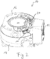
- FIG. 2 Sectional view of the vacuum device 10 shown in FIG Fig. 1 the cutting plane runs essentially through the lower part 16, the vacuum device 10 being rotated essentially through 180 °, that is to say the vacuum device is viewed from below.
- Electronics 20 can be seen which, as an alternative to or in addition to control unit 12, can form a control unit for accessory units connected to connections 14.
- the control unit 12 can include, for example, an engine controller.
- the electronics 20 can be designed as a control unit for one or more accessory units, for example in such a way that the accessory unit can also be operated when the control unit 12 is not connected.
- Fig. 3 shows a similar sectional view as Fig. 2 , although two connections 22 are also shown here, each of which is connected to a connection 14 of the vacuum device 10. Starting from a respective connection 22, a line 24 runs to a respective accessory unit, which is not shown here.
- the connections 14 are designed as sockets and the connections 22 as plugs.
- the in Fig. 4 The first exemplary connection diagram shown, two accessory units 26 are provided for connection to a vacuum device 10.
- the vacuum device 10 comprises a control unit 12 with two connections 14 for respective connections 22 of the accessory units 26.
- the connections 22 are each connected to the accessory unit 26 via a line 24, although it is also conceivable, for example, for the connection 22 to be formed directly on the accessory unit 26 .
- An accessory unit 26 could form a plug-in module.
- a connection 14 can also be connected to the control unit 12 or the vacuum device 10 via a line or in some other way, but can be designed separately.
- a second connection diagram is in Fig. 5 shown.
- a vacuum device 10 comprises a connection 14 provided on the housing of the vacuum device 10, an accessory unit 26 having a connection 22 for connection to the connection 14 arranged on the vacuum device 10 being provided.
- a control unit 12 comprises three connections 14.
- a connection 22 is provided for connection to one of the three connections 14 and connects the control unit 12 to an accessory unit 26 which is attached to and / or in the vacuum device 10.
- This accessory unit 26 can have, for example, a heating element for heating the vacuum device 10 and / or a sensor for detecting a parameter prevailing in or on the vacuum device 10.
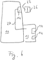
- the in Fig. 6 The third connection diagram shown, includes a vacuum device 10, a control unit 12 with two connections 14.
- a further connection 14 is provided on a housing part of the vacuum device 10 separately from the control unit 12.
- the connection 14 is connected to the control unit 12 via a line 27.
- the line 27 runs inside and / or in the housing of the vacuum device 10 or the control unit 12.
- the connection 14 can, for example, both for a mechanical connection of the accessory unit 26 to the vacuum device 10 and for an electrical and / or information technology connection of the accessory unit 26 be formed on the control unit 12.
- the control unit 12 can generally, as shown, be designed as a component which is arranged alongside the main housing of the vacuum device 10 and / or can also be integrated, that is to say can also be provided elsewhere in the vacuum device 10.
- the number and arrangement of further connections 14 can also vary.
- the accessory unit 26 has a connection 22 which is directly connected to the control unit 26. So there is no flexible line provided. However, this can be provided as an alternative or in addition.
- the accessory unit 26 is connected mechanically as well as electrically and / or in terms of information technology to the connection 14 of the vacuum device 10 via the connection 22.
- a fourth connection diagram is shown, in which a control unit 12 is arranged integrated in a housing of the vacuum device 10.
- the control unit 12 comprises a connection 14.
- the vacuum device 10 comprises a further connection 14, which is connected to the control unit via a line 27.
- Two accessory units (not shown) can be connected to the respective connections 14 via connections 22.
- FIG. 8 a vacuum device 10 with a connection 14 is shown.
- An accessory unit 26 can be connected to the connection 14, for example, which comprises a connection 22 for connecting the accessory unit 26 to the connection 14 of the vacuum device 10.
- the accessory unit 26 also includes a connector 14 for connecting one or more additional accessory units.
- An adapter 28, for example, which has a plurality of connections 14 for connecting further accessory units, can be connected to one of the connections 14 via a connection 22.
- a connection 14 of a vacuum device not shown here is shown, which has a supply contact 30 and a communication contact 32.
- An accessory unit 26 also has a supply contact 34 and a communication contact 36 at a connection 22.
- the accessory unit 26 can thus communicate with a control unit via the communication contacts 36 and 32 of the connections 22 and 14, respectively.
- an accessory unit 26 with only one supply contact 34 is shown.
- This accessory unit 26 can be supplied with electrical energy via the supply contacts 34 and 30.
- This accessory unit 26 illustrates an accessory unit of a generation older than the upper accessory unit 26.
- the vacuum device with the connection 14 can advantageously be designed in such a way that the lower accessory unit 26 can also be operated without automatic recognition of its type.
- a communication device and / or a communication contact can also be retrofitted to an accessory unit, for example via an identification unit 38 connected between the connection 22 of the lower accessory unit 26 and the connection 14 of the vacuum device.
- the identification unit 38 has a supply contact 30 at the connection 14 for supplying the accessory unit 26.
- At the connection 22, it has a communication contact 36 in addition to the supply contact 34.
- the recognition unit 38 can use this to output a signal, for example, which indicates the type of the connected accessory unit 26.
- the signal or the type can, for example, be preprogrammed and / or enterable.
Landscapes
- Engineering & Computer Science (AREA)
- Mechanical Engineering (AREA)
- General Engineering & Computer Science (AREA)
- Compressors, Vaccum Pumps And Other Relevant Systems (AREA)
- Non-Positive Displacement Air Blowers (AREA)
Claims (12)
- Appareil à vide (10), à savoir pompe à vide,
comportant au moins un raccord (14) pour un ensemble accessoire (26) et comportant une unité de commande (12) pour l'ensemble accessoire (26), dans lequel
le raccord (14) présente au moins un contact de communication (32) pour la liaison de communication de l'ensemble accessoire (26) avec l'unité de commande (12),
caractérisé en ce que
l'unité de commande (12) est réalisée pour reconnaître un ensemble accessoire (26) quant à son type, qui est raccordé au raccord (14), à partir d'un signal sortant de l'ensemble accessoire (26) et/ou d'une unité de reconnaissance pour l'ensemble accessoire et mis à disposition de l'unité de commande (12) via le contact de communication (32) du raccord (14). - Appareil à vide (10) selon la revendication 1,
caractérisé en ce que
le raccord (14) présente au moins un contact d'alimentation (30) pour l'alimentation électrique de l'ensemble accessoire (26). - Appareil à vide (10) selon l'une au moins des revendications précédentes,
caractérisé en ce que
l'unité de commande (12) est réalisée pour alimenter l'ensemble accessoire (26) avec des tensions différentes. - Appareil à vide (10) selon l'une au moins des revendications précédentes,
caractérisé en ce que
une interface série et/ou une interface bus pour l'ensemble accessoire (26) est prévue au niveau du raccord (14). - Appareil à vide (10) selon l'une au moins des revendications précédentes,
caractérisé en ce que
l'unité de commande (12) est réalisée pour traiter des données utiles fournies par l'ensemble accessoire (26). - Appareil à vide (10) selon l'une au moins des revendications précédentes,
caractérisé en ce que
l'unité de commande (12) est réalisée pour faire fonctionner l'ensemble accessoire (26) même si l'unité de commande (12) ne reconnaît pas l'ensemble accessoire (26) quant à son type. - Appareil à vide (10) selon l'une au moins des revendications précédentes,
caractérisé en ce que
l'unité de commande (12) est réalisée pour faire fonctionner simultanément plus d'un ensemble accessoire (26) raccordé au raccord (14). - Ensemble accessoire (26) pour un appareil à vide (10), à savoir pour une pompe turbomoléculaire, comportant un raccord (22) pour le raccordement à un raccord (14) de l'appareil à vide (10),
dans lequel
le raccord (22) de l'ensemble accessoire (26) présente au moins un contact de communication (36) pour la liaison de communication de l'ensemble accessoire (26),
caractérisé en ce que
l'ensemble accessoire (26) est réalisé pour émettre un signal par l'intermédiaire du contact de communication (36) de son raccord (22), ledit signal permettant de reconnaître l'ensemble accessoire (26) quant à son type. - Ensemble accessoire (26) selon la revendication 8,
caractérisé en ce que
l'ensemble accessoire (26) comprend aussi bien un actionneur qu'un capteur pour un paramètre qui peut être influencé par l'actionneur, et est réalisé pour émettre des données du capteur via le raccord (22). - Ensemble accessoire (26) selon la revendication 8 ou 9,
caractérisé en ce que
l'ensemble accessoire (26) comprend au moins un second raccord (14) pour raccorder un autre ensemble accessoire (26) à l'ensemble accessoire (26) et/ou à l'appareil à vide (10). - Unité de reconnaissance comprenant un premier raccord (22) pour le raccordement à un raccord d'un appareil à vide (10), à savoir d'une pompe turbomoléculaire, et un second raccord (14) pour le raccordement d'un ensemble accessoire (26) pour l'appareil à vide (10),
dans laquelle
le premier raccord (22) présente au moins un contact de communication (36),
l'unité de reconnaissance est réalisée pour émettre un signal par l'intermédiaire du contact de communication (36) du premier raccord (22), ledit signal permettant de reconnaître un ensemble accessoire (26) quant à son type, qui est raccordé ou susceptible d'être raccordé au second raccord (14). - Système comprenant un appareil à vide (10) selon l'une des revendications 1 à 7 et un ensemble accessoire (26) selon l'une des revendications 8 à 10 et/ou une unité de reconnaissance selon la revendication 11.
Priority Applications (2)
| Application Number | Priority Date | Filing Date | Title |
|---|---|---|---|
| EP18191876.4A EP3617520B1 (fr) | 2018-08-31 | 2018-08-31 | Appareil sous vide, unité accessoire et système |
| JP2019148482A JP2020056397A (ja) | 2018-08-31 | 2019-08-13 | 真空装置、アクセサリーユニットおよびシステム |
Applications Claiming Priority (1)
| Application Number | Priority Date | Filing Date | Title |
|---|---|---|---|
| EP18191876.4A EP3617520B1 (fr) | 2018-08-31 | 2018-08-31 | Appareil sous vide, unité accessoire et système |
Publications (2)
| Publication Number | Publication Date |
|---|---|
| EP3617520A1 EP3617520A1 (fr) | 2020-03-04 |
| EP3617520B1 true EP3617520B1 (fr) | 2021-05-26 |
Family
ID=63452480
Family Applications (1)
| Application Number | Title | Priority Date | Filing Date |
|---|---|---|---|
| EP18191876.4A Active EP3617520B1 (fr) | 2018-08-31 | 2018-08-31 | Appareil sous vide, unité accessoire et système |
Country Status (2)
| Country | Link |
|---|---|
| EP (1) | EP3617520B1 (fr) |
| JP (1) | JP2020056397A (fr) |
Families Citing this family (2)
| Publication number | Priority date | Publication date | Assignee | Title |
|---|---|---|---|---|
| ES2874703A1 (es) * | 2020-05-04 | 2021-11-05 | Cecotec Res And Development | Sistema de deteccion de accesorios para electrodomestico |
| EP4027043B1 (fr) * | 2021-12-23 | 2023-10-18 | Pfeiffer Vacuum Technology AG | Soupape à vide |
Citations (1)
| Publication number | Priority date | Publication date | Assignee | Title |
|---|---|---|---|---|
| DE102008019451A1 (de) * | 2008-04-17 | 2009-10-22 | Oerlikon Leybold Vacuum Gmbh | Vakuumpumpe |
Family Cites Families (14)
| Publication number | Priority date | Publication date | Assignee | Title |
|---|---|---|---|---|
| JPH0599669A (ja) * | 1991-10-04 | 1993-04-23 | Fuji Electric Co Ltd | 変位計 |
| JP3130890B2 (ja) * | 1999-02-25 | 2001-01-31 | セイコー精機株式会社 | 磁気軸受装置及び磁気軸受制御装置 |
| JP3442700B2 (ja) * | 1999-10-15 | 2003-09-02 | Smc株式会社 | 圧力センサ用制御装置および圧力センサシステム |
| JP2002021851A (ja) * | 2000-07-04 | 2002-01-23 | Koyo Seiko Co Ltd | 磁気軸受制御装置 |
| WO2007115633A1 (fr) * | 2006-03-31 | 2007-10-18 | J. Schmalz Gmbh | Dispositif de manutention à dépression |
| JP4919702B2 (ja) * | 2006-05-23 | 2012-04-18 | 株式会社キーエンス | センサ装置及びセンサシステム |
| JP5065703B2 (ja) * | 2007-02-15 | 2012-11-07 | 株式会社荏原製作所 | 回転機械装置における回転機械本体の機種識別方法、回転機械装置 |
| JP4897400B2 (ja) * | 2006-08-31 | 2012-03-14 | 船井電機株式会社 | スキャナ |
| JP4947493B2 (ja) * | 2007-10-09 | 2012-06-06 | 株式会社デンソー | センサ識別機能付き車両用エアコン制御装置 |
| DE202012006795U1 (de) * | 2012-07-13 | 2013-10-14 | Oerlikon Leybold Vacuum Gmbh | Vakuumpumpe sowie Vakuumpumpen-Anlage |
| DE102014206308B4 (de) * | 2014-04-02 | 2021-07-22 | J. Schmalz Gmbh | Handhabungsanlage und Verfahren zum Betreiben einer Handhabungsanlage |
| DE102014116555A1 (de) * | 2014-11-12 | 2016-05-12 | Pfeiffer Vacuum Gmbh | Vakuumgerät |
| JP6690213B2 (ja) * | 2015-12-09 | 2020-04-28 | セイコーエプソン株式会社 | ロボット、制御装置およびロボットシステム |
| WO2018066035A1 (fr) * | 2016-10-03 | 2018-04-12 | 三菱電機株式会社 | Unité de commande, système de climatisation et procédé pour commander un climatiseur |
-
2018
- 2018-08-31 EP EP18191876.4A patent/EP3617520B1/fr active Active
-
2019
- 2019-08-13 JP JP2019148482A patent/JP2020056397A/ja active Pending
Patent Citations (1)
| Publication number | Priority date | Publication date | Assignee | Title |
|---|---|---|---|---|
| DE102008019451A1 (de) * | 2008-04-17 | 2009-10-22 | Oerlikon Leybold Vacuum Gmbh | Vakuumpumpe |
Also Published As
| Publication number | Publication date |
|---|---|
| EP3617520A1 (fr) | 2020-03-04 |
| JP2020056397A (ja) | 2020-04-09 |
Similar Documents
| Publication | Publication Date | Title |
|---|---|---|
| EP1174781B1 (fr) | Appareil de transmission de signal | |
| EP3262907B1 (fr) | Unité modulaire de raccordement d'appareil de terrain | |
| EP3622488B1 (fr) | Adaptateur obd | |
| WO2020136010A2 (fr) | Module de base et module fonctionnel pour un système d'armoire électrique et système d'armoire électrique | |
| EP3617520B1 (fr) | Appareil sous vide, unité accessoire et système | |
| EP3622675A1 (fr) | Connecteur programmable | |
| EP1258957A1 (fr) | Ensemble d'interrupteurs | |
| WO2011006558A1 (fr) | Dispositif de transmission de données entre un bus de données série et des modules de travail tels que modules actionneurs et/ou modules e/s | |
| EP3647600B1 (fr) | Identification d'un périphérique connecté électriquement | |
| EP2327135A1 (fr) | Module fonctionnel et module de couplage d'une commande d'appareil de commutation, et système de commande d'appareil de commutation | |
| EP3029327B1 (fr) | Système constitué d'appareil à vide et d'unité de fonctionnement | |
| EP3028385B1 (fr) | Agencement pour raccorder un composant à un module de commande maître d'un véhicule | |
| DE19736581A1 (de) | Feldbusanordnung | |
| EP3097751B1 (fr) | Système adaptateur de communication, pour la technique de commande | |
| EP3888116B1 (fr) | Dispositif de commutation modulaire pour la commande d'au moins un entraînement électrique | |
| EP2369694B1 (fr) | Dispositif de raccordement et appareil d'automatisation | |
| DE102014224642B3 (de) | Feldbuskommunikationsmodul | |
| EP1652013A2 (fr) | Accouplement de bus sans connexions a fiches pour appareils d'automatisation | |
| EP3020975B1 (fr) | Appareil a vide | |
| EP4321949A1 (fr) | Dispositif de commande modulaire | |
| EP2196670B1 (fr) | Appareil pouvant être connecté avec un composant sous vide | |
| DE102019215606B3 (de) | Versorgungsmodul | |
| EP2987682B1 (fr) | Agencement pour des conduites électriques montées dans un véhicule automobile | |
| EP1353344B1 (fr) | Dispositif pour signaler des informations numériques | |
| AT519318B1 (de) | Lüftungssystem und Verfahren zur Steuerung eines Lüftungssystems |
Legal Events
| Date | Code | Title | Description |
|---|---|---|---|
| PUAI | Public reference made under article 153(3) epc to a published international application that has entered the european phase |
Free format text: ORIGINAL CODE: 0009012 |
|
| STAA | Information on the status of an ep patent application or granted ep patent |
Free format text: STATUS: THE APPLICATION HAS BEEN PUBLISHED |
|
| AK | Designated contracting states |
Kind code of ref document: A1 Designated state(s): AL AT BE BG CH CY CZ DE DK EE ES FI FR GB GR HR HU IE IS IT LI LT LU LV MC MK MT NL NO PL PT RO RS SE SI SK SM TR |
|
| AX | Request for extension of the european patent |
Extension state: BA ME |
|
| STAA | Information on the status of an ep patent application or granted ep patent |
Free format text: STATUS: REQUEST FOR EXAMINATION WAS MADE |
|
| 17P | Request for examination filed |
Effective date: 20200612 |
|
| RBV | Designated contracting states (corrected) |
Designated state(s): AL AT BE BG CH CY CZ DE DK EE ES FI FR GB GR HR HU IE IS IT LI LT LU LV MC MK MT NL NO PL PT RO RS SE SI SK SM TR |
|
| STAA | Information on the status of an ep patent application or granted ep patent |
Free format text: STATUS: EXAMINATION IS IN PROGRESS |
|
| 17Q | First examination report despatched |
Effective date: 20200811 |
|
| GRAP | Despatch of communication of intention to grant a patent |
Free format text: ORIGINAL CODE: EPIDOSNIGR1 |
|
| STAA | Information on the status of an ep patent application or granted ep patent |
Free format text: STATUS: GRANT OF PATENT IS INTENDED |
|
| INTG | Intention to grant announced |
Effective date: 20201207 |
|
| GRAS | Grant fee paid |
Free format text: ORIGINAL CODE: EPIDOSNIGR3 |
|
| GRAA | (expected) grant |
Free format text: ORIGINAL CODE: 0009210 |
|
| STAA | Information on the status of an ep patent application or granted ep patent |
Free format text: STATUS: THE PATENT HAS BEEN GRANTED |
|
| AK | Designated contracting states |
Kind code of ref document: B1 Designated state(s): AL AT BE BG CH CY CZ DE DK EE ES FI FR GB GR HR HU IE IS IT LI LT LU LV MC MK MT NL NO PL PT RO RS SE SI SK SM TR |
|
| REG | Reference to a national code |
Ref country code: GB Ref legal event code: FG4D Free format text: NOT ENGLISH |
|
| REG | Reference to a national code |
Ref country code: CH Ref legal event code: EP |
|
| REG | Reference to a national code |
Ref country code: AT Ref legal event code: REF Ref document number: 1396493 Country of ref document: AT Kind code of ref document: T Effective date: 20210615 |
|
| REG | Reference to a national code |
Ref country code: DE Ref legal event code: R096 Ref document number: 502018005400 Country of ref document: DE |
|
| REG | Reference to a national code |
Ref country code: IE Ref legal event code: FG4D Free format text: LANGUAGE OF EP DOCUMENT: GERMAN |
|
| REG | Reference to a national code |
Ref country code: LT Ref legal event code: MG9D |
|
| PG25 | Lapsed in a contracting state [announced via postgrant information from national office to epo] |
Ref country code: FI Free format text: LAPSE BECAUSE OF FAILURE TO SUBMIT A TRANSLATION OF THE DESCRIPTION OR TO PAY THE FEE WITHIN THE PRESCRIBED TIME-LIMIT Effective date: 20210526 Ref country code: HR Free format text: LAPSE BECAUSE OF FAILURE TO SUBMIT A TRANSLATION OF THE DESCRIPTION OR TO PAY THE FEE WITHIN THE PRESCRIBED TIME-LIMIT Effective date: 20210526 Ref country code: LT Free format text: LAPSE BECAUSE OF FAILURE TO SUBMIT A TRANSLATION OF THE DESCRIPTION OR TO PAY THE FEE WITHIN THE PRESCRIBED TIME-LIMIT Effective date: 20210526 Ref country code: BG Free format text: LAPSE BECAUSE OF FAILURE TO SUBMIT A TRANSLATION OF THE DESCRIPTION OR TO PAY THE FEE WITHIN THE PRESCRIBED TIME-LIMIT Effective date: 20210826 |
|
| REG | Reference to a national code |
Ref country code: NL Ref legal event code: MP Effective date: 20210526 |
|
| PG25 | Lapsed in a contracting state [announced via postgrant information from national office to epo] |
Ref country code: IS Free format text: LAPSE BECAUSE OF FAILURE TO SUBMIT A TRANSLATION OF THE DESCRIPTION OR TO PAY THE FEE WITHIN THE PRESCRIBED TIME-LIMIT Effective date: 20210926 Ref country code: GR Free format text: LAPSE BECAUSE OF FAILURE TO SUBMIT A TRANSLATION OF THE DESCRIPTION OR TO PAY THE FEE WITHIN THE PRESCRIBED TIME-LIMIT Effective date: 20210827 Ref country code: RS Free format text: LAPSE BECAUSE OF FAILURE TO SUBMIT A TRANSLATION OF THE DESCRIPTION OR TO PAY THE FEE WITHIN THE PRESCRIBED TIME-LIMIT Effective date: 20210526 Ref country code: SE Free format text: LAPSE BECAUSE OF FAILURE TO SUBMIT A TRANSLATION OF THE DESCRIPTION OR TO PAY THE FEE WITHIN THE PRESCRIBED TIME-LIMIT Effective date: 20210526 Ref country code: NO Free format text: LAPSE BECAUSE OF FAILURE TO SUBMIT A TRANSLATION OF THE DESCRIPTION OR TO PAY THE FEE WITHIN THE PRESCRIBED TIME-LIMIT Effective date: 20210826 Ref country code: LV Free format text: LAPSE BECAUSE OF FAILURE TO SUBMIT A TRANSLATION OF THE DESCRIPTION OR TO PAY THE FEE WITHIN THE PRESCRIBED TIME-LIMIT Effective date: 20210526 Ref country code: PL Free format text: LAPSE BECAUSE OF FAILURE TO SUBMIT A TRANSLATION OF THE DESCRIPTION OR TO PAY THE FEE WITHIN THE PRESCRIBED TIME-LIMIT Effective date: 20210526 Ref country code: PT Free format text: LAPSE BECAUSE OF FAILURE TO SUBMIT A TRANSLATION OF THE DESCRIPTION OR TO PAY THE FEE WITHIN THE PRESCRIBED TIME-LIMIT Effective date: 20210927 |
|
| PG25 | Lapsed in a contracting state [announced via postgrant information from national office to epo] |
Ref country code: NL Free format text: LAPSE BECAUSE OF FAILURE TO SUBMIT A TRANSLATION OF THE DESCRIPTION OR TO PAY THE FEE WITHIN THE PRESCRIBED TIME-LIMIT Effective date: 20210526 |
|
| PG25 | Lapsed in a contracting state [announced via postgrant information from national office to epo] |
Ref country code: SK Free format text: LAPSE BECAUSE OF FAILURE TO SUBMIT A TRANSLATION OF THE DESCRIPTION OR TO PAY THE FEE WITHIN THE PRESCRIBED TIME-LIMIT Effective date: 20210526 Ref country code: SM Free format text: LAPSE BECAUSE OF FAILURE TO SUBMIT A TRANSLATION OF THE DESCRIPTION OR TO PAY THE FEE WITHIN THE PRESCRIBED TIME-LIMIT Effective date: 20210526 Ref country code: EE Free format text: LAPSE BECAUSE OF FAILURE TO SUBMIT A TRANSLATION OF THE DESCRIPTION OR TO PAY THE FEE WITHIN THE PRESCRIBED TIME-LIMIT Effective date: 20210526 Ref country code: ES Free format text: LAPSE BECAUSE OF FAILURE TO SUBMIT A TRANSLATION OF THE DESCRIPTION OR TO PAY THE FEE WITHIN THE PRESCRIBED TIME-LIMIT Effective date: 20210526 Ref country code: RO Free format text: LAPSE BECAUSE OF FAILURE TO SUBMIT A TRANSLATION OF THE DESCRIPTION OR TO PAY THE FEE WITHIN THE PRESCRIBED TIME-LIMIT Effective date: 20210526 Ref country code: DK Free format text: LAPSE BECAUSE OF FAILURE TO SUBMIT A TRANSLATION OF THE DESCRIPTION OR TO PAY THE FEE WITHIN THE PRESCRIBED TIME-LIMIT Effective date: 20210526 |
|
| REG | Reference to a national code |
Ref country code: DE Ref legal event code: R097 Ref document number: 502018005400 Country of ref document: DE |
|
| REG | Reference to a national code |
Ref country code: CH Ref legal event code: PL |
|
| PLBE | No opposition filed within time limit |
Free format text: ORIGINAL CODE: 0009261 |
|
| STAA | Information on the status of an ep patent application or granted ep patent |
Free format text: STATUS: NO OPPOSITION FILED WITHIN TIME LIMIT |
|
| PG25 | Lapsed in a contracting state [announced via postgrant information from national office to epo] |
Ref country code: MC Free format text: LAPSE BECAUSE OF FAILURE TO SUBMIT A TRANSLATION OF THE DESCRIPTION OR TO PAY THE FEE WITHIN THE PRESCRIBED TIME-LIMIT Effective date: 20210526 |
|
| REG | Reference to a national code |
Ref country code: BE Ref legal event code: MM Effective date: 20210831 |
|
| PG25 | Lapsed in a contracting state [announced via postgrant information from national office to epo] |
Ref country code: LI Free format text: LAPSE BECAUSE OF NON-PAYMENT OF DUE FEES Effective date: 20210831 Ref country code: CH Free format text: LAPSE BECAUSE OF NON-PAYMENT OF DUE FEES Effective date: 20210831 |
|
| 26N | No opposition filed |
Effective date: 20220301 |
|
| PG25 | Lapsed in a contracting state [announced via postgrant information from national office to epo] |
Ref country code: IS Free format text: LAPSE BECAUSE OF FAILURE TO SUBMIT A TRANSLATION OF THE DESCRIPTION OR TO PAY THE FEE WITHIN THE PRESCRIBED TIME-LIMIT Effective date: 20210926 Ref country code: LU Free format text: LAPSE BECAUSE OF NON-PAYMENT OF DUE FEES Effective date: 20210831 Ref country code: AL Free format text: LAPSE BECAUSE OF FAILURE TO SUBMIT A TRANSLATION OF THE DESCRIPTION OR TO PAY THE FEE WITHIN THE PRESCRIBED TIME-LIMIT Effective date: 20210526 |
|
| PG25 | Lapsed in a contracting state [announced via postgrant information from national office to epo] |
Ref country code: IE Free format text: LAPSE BECAUSE OF NON-PAYMENT OF DUE FEES Effective date: 20210831 Ref country code: FR Free format text: LAPSE BECAUSE OF NON-PAYMENT OF DUE FEES Effective date: 20210831 Ref country code: BE Free format text: LAPSE BECAUSE OF NON-PAYMENT OF DUE FEES Effective date: 20210831 |
|
| PG25 | Lapsed in a contracting state [announced via postgrant information from national office to epo] |
Ref country code: CY Free format text: LAPSE BECAUSE OF FAILURE TO SUBMIT A TRANSLATION OF THE DESCRIPTION OR TO PAY THE FEE WITHIN THE PRESCRIBED TIME-LIMIT Effective date: 20210526 |
|
| PG25 | Lapsed in a contracting state [announced via postgrant information from national office to epo] |
Ref country code: HU Free format text: LAPSE BECAUSE OF FAILURE TO SUBMIT A TRANSLATION OF THE DESCRIPTION OR TO PAY THE FEE WITHIN THE PRESCRIBED TIME-LIMIT; INVALID AB INITIO Effective date: 20180831 |
|
| PG25 | Lapsed in a contracting state [announced via postgrant information from national office to epo] |
Ref country code: MK Free format text: LAPSE BECAUSE OF FAILURE TO SUBMIT A TRANSLATION OF THE DESCRIPTION OR TO PAY THE FEE WITHIN THE PRESCRIBED TIME-LIMIT Effective date: 20210526 |
|
| PG25 | Lapsed in a contracting state [announced via postgrant information from national office to epo] |
Ref country code: MT Free format text: LAPSE BECAUSE OF FAILURE TO SUBMIT A TRANSLATION OF THE DESCRIPTION OR TO PAY THE FEE WITHIN THE PRESCRIBED TIME-LIMIT Effective date: 20210526 |
|
| REG | Reference to a national code |
Ref country code: AT Ref legal event code: MM01 Ref document number: 1396493 Country of ref document: AT Kind code of ref document: T Effective date: 20230831 |
|
| PG25 | Lapsed in a contracting state [announced via postgrant information from national office to epo] |
Ref country code: AT Free format text: LAPSE BECAUSE OF NON-PAYMENT OF DUE FEES Effective date: 20230831 |
|
| PG25 | Lapsed in a contracting state [announced via postgrant information from national office to epo] |
Ref country code: AT Free format text: LAPSE BECAUSE OF NON-PAYMENT OF DUE FEES Effective date: 20230831 |
|
| PGFP | Annual fee paid to national office [announced via postgrant information from national office to epo] |
Ref country code: IT Payment date: 20250825 Year of fee payment: 8 |
|
| PGFP | Annual fee paid to national office [announced via postgrant information from national office to epo] |
Ref country code: GB Payment date: 20250820 Year of fee payment: 8 |
|
| PGFP | Annual fee paid to national office [announced via postgrant information from national office to epo] |
Ref country code: CZ Payment date: 20250827 Year of fee payment: 8 |
|
| PG25 | Lapsed in a contracting state [announced via postgrant information from national office to epo] |
Ref country code: TR Free format text: LAPSE BECAUSE OF FAILURE TO SUBMIT A TRANSLATION OF THE DESCRIPTION OR TO PAY THE FEE WITHIN THE PRESCRIBED TIME-LIMIT Effective date: 20210526 |
|
| PGFP | Annual fee paid to national office [announced via postgrant information from national office to epo] |
Ref country code: DE Payment date: 20251029 Year of fee payment: 8 |
|
| PGFP | Annual fee paid to national office [announced via postgrant information from national office to epo] |
Ref country code: AT Payment date: 20260410 Year of fee payment: 5 |