EP3617721A1 - Reconnaissance d'impédance d'un consommateur d'une station de charge - Google Patents
Reconnaissance d'impédance d'un consommateur d'une station de charge Download PDFInfo
- Publication number
- EP3617721A1 EP3617721A1 EP19193371.2A EP19193371A EP3617721A1 EP 3617721 A1 EP3617721 A1 EP 3617721A1 EP 19193371 A EP19193371 A EP 19193371A EP 3617721 A1 EP3617721 A1 EP 3617721A1
- Authority
- EP
- European Patent Office
- Prior art keywords
- charging
- consumer
- detection
- electrodes
- charging station
- Prior art date
- Legal status (The legal status is an assumption and is not a legal conclusion. Google has not performed a legal analysis and makes no representation as to the accuracy of the status listed.)
- Granted
Links
Images


Classifications
-
- G—PHYSICS
- G01—MEASURING; TESTING
- G01R—MEASURING ELECTRIC VARIABLES; MEASURING MAGNETIC VARIABLES
- G01R29/00—Arrangements for measuring or indicating electric quantities not covered by groups G01R19/00 - G01R27/00
- G01R29/02—Measuring characteristics of individual pulses, e.g. deviation from pulse flatness, rise time or duration
- G01R29/027—Indicating that a pulse characteristic is either above or below a predetermined value or within or beyond a predetermined range of values
-
- H—ELECTRICITY
- H02—GENERATION; CONVERSION OR DISTRIBUTION OF ELECTRIC POWER
- H02J—ELECTRIC POWER NETWORKS; CIRCUIT ARRANGEMENTS OR SYSTEMS FOR SUPPLYING OR DISTRIBUTING ELECTRIC POWER; SYSTEMS FOR STORING ELECTRIC ENERGY
- H02J7/00—Circuit arrangements for charging or discharging batteries or for supplying loads from batteries
- H02J7/40—Circuit arrangements for charging or discharging batteries or for supplying loads from batteries characterised by the exchange of charge or discharge related data
- H02J7/443—Circuit arrangements for charging or discharging batteries or for supplying loads from batteries characterised by the exchange of charge or discharge related data using passive battery identification means, e.g. resistors or capacitors
- H02J7/445—Circuit arrangements for charging or discharging batteries or for supplying loads from batteries characterised by the exchange of charge or discharge related data using passive battery identification means, e.g. resistors or capacitors in response to measured battery parameters, e.g. voltage, current or temperature profile
-
- H—ELECTRICITY
- H02—GENERATION; CONVERSION OR DISTRIBUTION OF ELECTRIC POWER
- H02J—ELECTRIC POWER NETWORKS; CIRCUIT ARRANGEMENTS OR SYSTEMS FOR SUPPLYING OR DISTRIBUTING ELECTRIC POWER; SYSTEMS FOR STORING ELECTRIC ENERGY
- H02J7/00—Circuit arrangements for charging or discharging batteries or for supplying loads from batteries
- H02J7/60—Circuit arrangements for charging or discharging batteries or for supplying loads from batteries including safety or protection arrangements
- H02J7/685—Circuit arrangements for charging or discharging batteries or for supplying loads from batteries including safety or protection arrangements using connection detecting circuits
-
- Y—GENERAL TAGGING OF NEW TECHNOLOGICAL DEVELOPMENTS; GENERAL TAGGING OF CROSS-SECTIONAL TECHNOLOGIES SPANNING OVER SEVERAL SECTIONS OF THE IPC; TECHNICAL SUBJECTS COVERED BY FORMER USPC CROSS-REFERENCE ART COLLECTIONS [XRACs] AND DIGESTS
- Y02—TECHNOLOGIES OR APPLICATIONS FOR MITIGATION OR ADAPTATION AGAINST CLIMATE CHANGE
- Y02T—CLIMATE CHANGE MITIGATION TECHNOLOGIES RELATED TO TRANSPORTATION
- Y02T10/00—Road transport of goods or passengers
- Y02T10/60—Other road transportation technologies with climate change mitigation effect
- Y02T10/70—Energy storage systems for electromobility, e.g. batteries
-
- Y—GENERAL TAGGING OF NEW TECHNOLOGICAL DEVELOPMENTS; GENERAL TAGGING OF CROSS-SECTIONAL TECHNOLOGIES SPANNING OVER SEVERAL SECTIONS OF THE IPC; TECHNICAL SUBJECTS COVERED BY FORMER USPC CROSS-REFERENCE ART COLLECTIONS [XRACs] AND DIGESTS
- Y02—TECHNOLOGIES OR APPLICATIONS FOR MITIGATION OR ADAPTATION AGAINST CLIMATE CHANGE
- Y02T—CLIMATE CHANGE MITIGATION TECHNOLOGIES RELATED TO TRANSPORTATION
- Y02T10/00—Road transport of goods or passengers
- Y02T10/60—Other road transportation technologies with climate change mitigation effect
- Y02T10/7072—Electromobility specific charging systems or methods for batteries, ultracapacitors, supercapacitors or double-layer capacitors
Definitions
- the invention relates to a charging station (synonymously also called “base station”) for a consumer, in particular a robot with the features of the preamble of claim 1.
- the invention further relates to an arrangement comprising the charging station and the robot and a method.
- Consumers especially energy-autonomous consumers, e.g. B. battery operated handheld devices such as vacuum cleaners etc., in particular moving (household) robots, e.g. B. vacuuming robots, robotic lawnmowers, are powered by an energy storage device, in particular a battery, and require a charging or base station at which they can charge their energy storage device.
- the base station generally has two charging contacts or electrodes, to which the charging voltage is applied and which can connect to the corresponding charging electrodes of a counter interface of the consumer.
- the present facts and also the present invention are explained in sections by way of example with the aid of a robot, with all of the explanations correspondingly being transferable to other devices, in particular hand-held devices, which dock with charging stations.
- the robot starts the charging station independently and usually unsupervised when the state of charge of the energy storage device has dropped significantly.
- the base station usually also serves as a resting point for the consumer when he has finished his work. For many consumers, the fact that the charging voltage is applied to their charging electrodes is also an indication that they have reached their rest position at the base station.
- the charging voltage is usually continuously applied to the mostly exposed charging electrodes of the base station. If a metallic foreign body (e.g. a paper clip, a metal foil or a piece of metallic cleaning wool) touches both electrodes, a short circuit can occur. A very low-resistance "saturated" short circuit is usually avoided by a protective shutdown or current limitation of the power supply of the base station, which respond when the expected charging current is significantly exceeded. However, the charging currents when charging the consumer energy storage are in the range of several amperes, so that such a protective circuit may not respond if the short-circuiting metal part has a corresponding not very low resistance value.
- a metallic foreign body e.g. a paper clip, a metal foil or a piece of metallic cleaning wool
- a current of several amperes can be sufficient to heat a short-circuiting metal part until it glows and thereby start or ignite a fire.
- a conductive foreign body still has easily flammable build-up such as dirt, grease or oil or plastics.
- Typical examples of such conductive foreign bodies are metallic cleaning wool or thin metal threads woven into textiles.
- the risk of a short circuit due to metal parts falling or being accidentally "carried away" to the base station by pets is particularly high if the charging electrodes of the base station are at ground level. But even with side-mounted contacts, for. B. by a short circuit in the blouse sleeves of the user, if the user is handling the base station.
- the publication EP 1 921 523 A2 describes a system in which, without a robot, a voltage is only applied to the charging electrodes of the base station with a high resistance via a precisely specified resistance, so that a short circuit leads to a harmlessly lower current flow.
- the robot contains the counterpart to the resistance in the base station, so that when the robot is docked, a defined series resistance is created and a precisely defined current flows through the two resistors. Only when exactly this predetermined current flows, both the base station and the robot switch to the charging mode, and the actual charging voltage with a high charging current is applied by the base station to the charging contacts.
- a method for electrically charging an electrical energy store by means of a charging station is known, an electrical one Docking of the electrical energy storage device is detected at the charging station, characterized in that the charging station supplies the docked energy storage device with an electrical charging energy when communication signals exchanged between the charging station and the docked energy storage device are detected.
- the invention further relates to a charging station, an electrical energy store and a mobile device.
- a robot control unit which contains a signal transmission unit for electrical connection to a first docking terminal and for transmitting a predetermined detection signal, and which contains a signal reception unit for electrical connection to a second docking terminal.
- the signal receiving unit receives a predetermined feedback signal corresponding to the predetermined detection signal
- the robot control unit confirms that the robot with the docking terminal group has successfully docked to a docking station.
- the invention is therefore based on the object of preventing a critical current flow through a short-circuiting foreign body in a charging station for a consumer, in particular a robot, and thus preventing a fire from occurring.
- the object of the invention is a charging station which is suitable and / or designed for a designated consumer, in particular a robot.
- the charging station can also be referred to as a base station, particularly in connection with a robot.
- the charging station is in particular arranged in a stationary manner and is used to charge the consumer, in particular an energy store of the consumer.
- the energy store can be designed as a rechargeable battery, battery, capacitive energy store, etc.
- the charging station can also provide a garage for the consumer, in particular a robot.
- the consumer is designed in particular as a robot, particularly preferably as a household robot and / or mobile robot and / or autonomous robot.
- the robot is implemented as a lawnmower robot or as a vacuum cleaner robot.
- the robot can also be designed as a flying robot, in particular a drone.
- the consumer can dock or dock on the charging station to be charged.
- the charging station has a charging interface, which is formed by electrodes (hereinafter also referred to as "charging electrodes").
- the charging interface particularly preferably has at least or exactly two electrodes, one electrode being designed as a positive pole and the other electrode as a ground pole or negative pole.
- the consumer has (as intended, see above) a counter interface that is compatible and / or complementary to the charging interface.
- the charging interface and counter interface can be coupled in such a way that a charging current can be transmitted.
- the connection between the charging interface and the counter interface is contacting and in particular not contactless.
- the charging current is thus transmitted in particular via cables, conductor tracks and other metallic conductors.
- the consumer has a charging device and an energy store, the counter interface being connected to the energy store via the charging device, so that the energy store can be charged via the counter interface.
- a charging voltage or a charging current can be applied to the counter interface, which serves to charge the energy store.
- the charging station has a supply device for supplying the charging interface, in particular with energy and / or with charging current and / or charging voltage.
- the supply device can be placed in a charge state and in a non-charge state. In the charging state, a charging current and / or a charging voltage for charging the energy store is provided at the charging interface. In the non-charging state, the charging interface is de-energized, in particular by the supply device.
- the charging station has a detection device for detecting the coupling of the consumer to the charging interface.
- the detection device can output a status “consumer coupled / docked” or “consumer not coupled / docked”.
- the detection device can be designed as a digital data processing device, such as a microprocessor or the like, alternatively or additionally, the detection device is designed as an analog circuit.
- the detection device in particular in terms of programming and / or circuit technology, be designed to apply a test signal (voltage and / or current) to the charging interface when the supply device is not in charge, and in this connection (i.e. before and / or during and / or after application of the test signal) to detect an electrical variable based on the complex electrical output impedance of the charging interface as a detection variable for detecting the coupling of the consumer to the charging interface.
- the electrical variable is in particular the voltage between the electrodes or the current flowing through at least one of the electrodes.
- the detection device thus registers an electrical variable which is generated or at least influenced by the electrical output impedance.
- the output impedance is the one that is seen at the charging interface with respect to the charging station to the outside, that is to say to the “consumer side”.
- the detection device leads to a detection which is based on the electrical properties and / or impedance of the energy store and / or consumer, which thus rules out confusion with foreign bodies, passive objects, in particular the metallic interference objects.
- the application of the test signal may result in only a reduced energy input into a metallic interference object, so that the risk of fire based on a current flow through a metallic interference object is reduced.
- the invention thus provides reliable detection of the coupling of the consumer to the charging interface, while at the same time reducing the risk of fire.
- the charging station can form a retrofit system for existing consumers without changing the consumer itself, that is, it can only be used by exchanging the charging station. Specific adjustments to the consumer are not necessary.
- the basic problems and tasks are unchanged compared to a passive detection method and also the basic structure of the loading or Base station consisting of a power supply unit, which generates the charging voltage, as well as a downstream switching element, which it connects to the charging contacts when the consumer is present, is retained.
- the switching element switches between the charge and the non-charge state.
- the switching element is part or therefore also forms a separating device, as will be explained in more detail below.
- the methods considered in the parallel patent application are purely passive methods, which are based on the detection of leakage currents through the input protection diode or the battery voltage measurable on the contact electrodes of the consumer (also called “counter electrodes”). In any case, the quantities to be detected are determined directly or indirectly by the output voltage of the consumer battery.
- the disadvantage of the passive method is that it is based on an existing battery voltage of the consumer. If the consumer, especially the robot, drives onto the station independently, this will of course be present, because the robot cannot move autonomously without an adequate energy supply.
- Most robot batteries - especially lithium-ion batteries - have their own battery management system (BMS), which protects the battery against damage caused by a deep discharge that is harmful or even dangerous in the case of lithium-ion batteries if the battery voltage falls below a protection threshold
- Robot electronics are electrically isolated so that no further power can be drawn from the battery.
- a robot with a robot battery separated by the BMS can principally not recognized by the passive methods if z. B. the user manually places the robot on the base station for charging. Without the charging voltage, the battery is no longer activated by the BMS.
- the active detection methods described here are slower due to an impedance measurement and have to work with test voltages or currents (test signal) so that they also enter energy into a possible short circuit. Appropriate circuit design must then ensure that this energy input is so small that it cannot lead to a fire.
- the energy input through the charging station now makes it possible for a consumer to be recognized completely independently of the state of charge of the battery and then to be charged by the charging voltage applied.
- the detection method has the task of clearly, reliably and (in the case of an independently docking robot) also recognizing the consumer sufficiently quickly and being able to distinguish it in particular from a short circuit via the charging electrodes.
- the characteristic used here is the (complex or complex value) impedance of the consumer or a short circuit.
- a short circuit in the form of a metallic foreign body that bridges the charging electrodes almost exclusively has a purely ohmic impedance. Only very small proportions of inductive (in the nH range) or capacitive (only in the pF range) nature are possible.
- the invention relates in particular to a system consisting of the charging station / base station and a mobile autonomous system, the robot.
- autonomous is important here because it does not monitor the entire system. It is an unsupervised operation that has to meet higher safety requirements than, for example, the use of a hand-held vacuum cleaner, in which a user can intervene in operation if he discovers a safety problem.
- the problem that the invention solves for a robot can also occur in a similar form for manually operated cleaning devices.
- these are battery-operated handheld devices.
- a plug-in power supply which is connected to the counterpart in the vacuum cleaner via a cable with a connected plug connector
- the problem does not arise, since there are no large, exposed electrodes.
- a consumer or device e.g. B. a wet vacuum cleaner, which has a kind of standing charging station on which the device can be parked and charged there, but has similar problems.
- the device is mechanically z. B: Suspended at the charging station and supplied with charging current via relatively large exposed electrodes (not on the floor but laterally near the floor). Whenever the device is removed from the charging station, e.g.
- the charging electrodes of the charging station are open and there is in principle the same danger as with the robot system. If the device is removed, e.g. B. the user sucks another room or even puts the vacuum cleaner unused in another room (not so rare in multi-storey apartments), the charging station is in an unattended operation - that is, exactly the same case as with the robot system. This safety problem can be solved by the invention in exactly the same way as with the robot.
- the detection quantity or the electrical quantity contains the imaginary part of the output impedance, that is to say its capacitive or inductive part. In particular, only this portion is used. In particular, this is the electrical output capacitance.
- the real part of the output impedance is also taken into account in the detection variable, in particular the ohmic output resistance between the electrodes. "Exit" is again to be understood as above.
- the electrical quantity is therefore any complex impedance with a reactive and / or capacitive component.
- Equivalent circuit diagrams are e.g. B. the series or parallel connection of capacitor and resistor. It can be assumed that such impedances generally differ from consumers and foreign bodies and thus an effective distinction can also be made between the docking / undocking of the consumer and a foreign body.
- the charging station have a load resistance which is arranged in terms of circuitry between the electrodes of the charging interface.
- This can e.g. B. trigger discharge processes in the consumer, which are initiated by applying the test signal.
- dynamic processes or impedance profiles can be triggered, which then again have different and thus distinguishable characteristics for docked / undocked consumers and interference objects.
- the load resistance is preferably at least high-resistance.
- High-resistance is understood to mean in particular a resistance value which is dimensioned such that at least 95%, preferably at least 98%, of the residual storage voltage applied to the electrodes of the charging interface drops.
- the load resistance can be greater than 1 MOhm, preferably greater than 5 MOhm and in particular greater than 9 MOhm.
- the load resistance is preferably dimensioned such that less than 95%, preferably less than 90% and in particular less than 85% of the residual storage voltage applied to the electrodes of the charging interface drops across the load resistor.
- a moderately high impedance load resistance that interference, which can arise in the case of very high impedance load resistances due to an antenna effect of the load resistors during voltage measurement, is eliminated or at least reduced. Since such interferences can arise, in particular due to electrostatic charges and discharges, the alternative design results in a higher level of interference immunity.
- the charging device of the consumer has a blocking diode.
- the blocking diode can also be referred to as an input protection diode.
- this diode serves as protection against polarity reversal if the consumer should be placed incorrectly on the electrodes, and on the other hand it has the task of preventing a possible short circuit if the counter-electrodes of the consumer are short-circuited by a metal part, for example because a consumer is attached to the side Counter electrodes touched a metallic chair leg with both electrodes.
- the blocking diode also serves to prevent the consumer from being discharged via the charging station if the consumer is on the charging station with a charged energy store, but the charging station is currently not receiving any mains voltage, for example due to a power failure.
- This diode is preferably a power diode which must be able to switch through the charging current of the consumer, which is several amperes, largely without loss.
- the charging station has a control device.
- the control device can be designed as a separate device or form an integral part of the detection device. In the event that the control device is designed as a separate device, it can be designed as a digital processing device and / or circuit processing device.
- the control device is designed in particular in terms of program technology and / or circuit technology to switch the supply device between the charge state and the non-charge state on the basis of the detection variable. For this purpose, the control device can determine the detection variable and / or a status based on the detection variable, such as, for. B. "Consumers coupled / docked" or “Consumers not coupled / docked". In particular, the control device is designed with the status "consumer coupled / docked "or a corresponding detection variable to switch the supply device from the non-charging state to the charging state.
- the charging station has a disconnecting device for interrupting the charging current and / or the charging voltage.
- the separating device is designed in particular for decoupling the charging interface, in particular at least one electrode of the charging interface.
- the separator is designed as a switch (the above switching element), e.g. B. formed as a relay or MOS-FET.
- the control device is designed to control the separating device in order to switch the supply device between the charge state and the non-charge state.
- the charging station has a charging current test device for detecting the charging current.
- a charging current test device for detecting the charging current.
- the charging current is monitored by the charging current testing device, so that it can be recognized when the consumer stops or ends the charging process. In this case, the charging current will collapse and / or go to 0.
- a lack of charging current is a necessary condition for undocking the consumer, but it is not a sufficient condition.
- the consumer drives onto the charging station with partially discharged energy storage, fully charges the energy storage there and then does not consume any further charging current but still does not leave the charging station because his work is finished and he is now in the standby position on the charging station remains.
- a small supply current for the current consumption of the consumer electronics is taken up by the charging station or from the energy store depends on the type of the consumer. In standby mode, power is optionally drawn exclusively from the energy store, for example.
- the control device controls the supply device to go from the charging state to the non-charging state as soon as it is recognized via the charging current and / or the charging current test device that the consumer has assumed the status "consumer not charging".
- the detection device is designed in terms of program technology and / or circuit technology to detect a further electrical variable based on the charging current as a further detection variable for detecting the charging of the consumer at the charging interface when the supply device is in a charging state.
- the charging station contains a test signal generator, in particular a voltage source (or also current source), for applying a pulsed source voltage (or for impressing a specific current signal) in the form of the test signal between the electrodes before and / or during the detection of the electrical variable, and the detection device is designed to carry out the detection of the electrical variable in the time domain.
- a voltage pulse or a voltage jump is specified as the test signal.
- the impulse / step response is then measured and evaluated by the detection device.
- a constant voltage source is therefore applied in the form of a pulse.
- the test signal generator can be an independent signal source, it can also be implicitly created by other components such as e.g. B. the supply device and possibly the separation device are formed.
- the pulse or jump in the voltage can also be generated by interrupting the state of charge or the charging of the connected consumer in order to carry out the impedance measurement.
- the charging voltage is therefore switched off, which leads to a voltage drop that drops in particular.
- the step response is then measured and evaluated.
- the interruption is or leads to the generation of the voltage pulse (the falling edge of the pulse).
- the hardware setup can be very similar to the setup for a passive measurement process. If you implement the process with a microcontroller, you can even use identical hardware and only have to adapt the respective control software. The advantages associated with this will be discussed later.
- the impulse response of the system is measured periodically at the charging electrodes.
- a short stimulus / stimulation pulse (duration tp e.g. 0.2 ms) is periodically given to the charging electrodes as a test signal.
- a relay is less suitable as a switching element and a MOSFET transistor should preferably be used.
- the control voltage at the gate is controlled by a control unit high, the MOSFET is turned on and the charging voltage is briefly applied to the charging electrodes. Then one can then measure the charging voltage during the pulse duration tp of the stimulation pulse.
- the signal curve will be similar, but the amplitude of the signal is usually significantly lower up to almost zero in the case of a full (very low-resistance) short circuit.
- a capacitor (known to be present in the intended consumer) is noticeable on or between the counter electrodes of the consumer.
- the voltage when the stimulus pulse is applied will rise somewhat longer because of the charging of the capacitor and then remain constant for the rest of the pulse duration tp.
- the capacitor is slowly switched over an internal resistance in the charging station between the electrodes, e.g. B. discharge resistance. This results in the typical exponential discharge curve of an RC combination that runs asymptotically towards zero (RC charge / discharge curve).
- the load resistance is optionally not absolutely necessary either, since a discharge of the known internal capacitance of the consumer is not necessarily required for the measurement. Without load resistance, however, the measurement is very high-impedance and is therefore sensitive to electrostatic charging, as can easily occur especially near synthetic floors, especially near the floor.
- the stimulus pulse should or should be generated depends on how quickly a consumer should be detected. If the consumer drives onto the station independently, the detection must take place quickly (e.g. in less than 100 ms), so that the charging voltage can be applied in good time via the switching element (transition from non-to the charging state) before the consumer switches the Loses contact with the charging electrodes. In this case, the stimulus pulses must be applied to the charging electrodes at short intervals (e.g. 30 ms).
- the product of the number of pulses per second and the pulse duration tp determine the energy introduced into a possible short circuit per second. For safety reasons, it should be as low as possible to reduce the risk of fire.
- a self-holding effect also occurs in the present case: as soon as the consumer is recognized when docking and the charging voltage has been applied via the switching element, only the charging voltage can be determined on the electrodes, ie the impedance measurement can no longer be carried out. Undock detection is therefore required here as well as for the passive methods. You can do this e.g. B. as well as in the passive method, in that From time to time (e.g. every few seconds) the charging voltage is interrupted and the detection process is then carried out again during the interruption. In particular, even the stimulus pulse during the interruption is superfluous, since the charging voltage was present immediately before the interruption and the capacitor was charged in the consumer. As with the passive methods, the charging current can also be measured and monitored very advantageously in order to prevent an interruption of the charging process that is technically disadvantageous with regard to the battery. The corresponding considerations for passive methods can be applied here analogously.
- the detection device is therefore designed to determine a detection of the consumer only if the electrical variable in the time range corresponds to an RC charging and / or discharging curve between the electrodes, which is in accordance with the input capacity of the consumer connected as intended stands, d. H. Correspondingly expected values known or dimensioned by the intended consumer are determined.
- one or two or more measuring points in particular a complete curve profile, in particular a slope and / or edge shape of the profile of the electrical variable, eg. B. the voltage between the electrodes recorded and evaluated.
- the typical RC course exponentially asymptotically goes to zero when the test signal is removed.
- the output capacitance at the electrodes and thus the input capacitance of the consumer in the docked state are determined.
- the consumer is detected when a capacitance of at least 5, 8, 10, 15 or 20 nF has been detected, otherwise there is no detection, that is to say as a result that no intended consumer is currently connected.
- the detection is thus determined in particular by the fact that at a predeterminable point in time after the test signal is switched off, at least one predeterminable residual voltage is present between the electrodes.
- the values are dimensioned based on the electrical parameters of the charging station and the intended consumer.
- the charging station contains a test signal generator, in particular a voltage source for applying a test signal between the electrodes before and / or during the detection of the electrical variable, and the detection device is designed to carry out the detection of the electrical variable in the frequency range.
- a test signal is thus applied to the electrodes and an electrical quantity is registered there, and then the spectrum of the registered signal is viewed in whole or in part, and conclusions are drawn about the presence of the consumer, in particular the robot.
- this is a simple sine signal of a frequency that is changed, or z.
- B. a multi-tone signal (a superposition of several sine waves of different frequencies). But a non-periodic signal can also be used.
- a typical example would be a noise signal.
- an AC voltage e.g. B. different frequencies and the frequency response completely or partially of the overall arrangement (charging station and possibly consumers and / or foreign bodies) determined and evaluated.
- a measurement in the frequency domain is also possible. So you do not measure the impulse or step response of the system located on the charging electrodes, but z. B. the frequency response. An example will be shown below.
- a voltage measurement input to or on the microcontroller is superfluous - if available.
- the microcontroller has an additional pulse input that is connected to a frequency counter. In any case, a frequency counter must be provided in the general case.
- the frequency counter or an associated circuit is e.g. B. an oscillator circuit from which a rectangular output signal is derived.
- the core is a parallel resonant circuit formed by a capacitor and the coil.
- the value of the capacitor should be in the order of magnitude of the expected consumer capacitance (e.g. at 33 nF) and the coil should then be selected so that the resonant frequency of the resonant circuit is between 30 kHz and 500 kHz. Lower frequencies are unfavorable because this results in long settling times, higher ones can lead to problems with parasitic elements and, moreover, can cause undesirable high-frequency interference.
- a comparator connected to the resonant circuit causes the resonant circuit to oscillate at the resonance frequency via feedback resistors.
- a comparator with complementary outputs is used.
- Such comparator ICs are known to those skilled in the art, for example as Linear Technology IC LT1713 / LT1714.
- a (second) comparator stage connected downstream at the output of the (first) comparator only serves to convert the oscillator signal into a clean square-wave signal, which can then be fed to the frequency counter.
- the reference level for this (second) comparator is generated via resistors or an ohmic voltage divider.
- the resonant circuit is connected to the electrodes via the coupling capacitors.
- the charging electrodes are therefore AC parallel to the resonant circuit, while the coupling capacitors also provide galvanic isolation.
- the capacitance values of the coupling capacitors should be large compared to the value of the capacitor of the resonant circuit, that is to say 2.2 ⁇ F in this example. Unipolar ceramic capacitors are preferred.
- the capacitance measurement itself can only take place when the switching element is open (non-charging state), because when the switching element is closed, the circuit would primarily "see” a very large smoothing capacitor of the charging voltage source and would not be able to record the additional contribution of the consumer capacity (input capacity).
- the frequency counting can easily be carried out by the controlling microcontroller itself.
- the output of the above-mentioned (second) comparator stage is connected to a pulse input of the microcontroller, which is internally connected to a counter stage. If you first reset the counter and then let it run for a predefined time, it becomes all the impulses at the input of the microcontroller register and after the predefined time the counter reading is proportional to the oscillation frequency of the resonant circuit.
- the resonant circuit will oscillate at its resonance frequency.
- the two coupling capacitors towards the resonant circuit have de facto no influence, since the parasitic capacitance between the charging electrodes will at most be a few pF.
- the consumer has docked, its input capacitance is in series with the two coupling capacitors in parallel with the resonant circuit capacitor. Since the capacitance values of the coupling capacitors are significantly larger than the input capacitance of the consumer, its value will dominate the series connection of the three capacitors. Consequently, when the consumer is docked, the input capacitance is de facto parallel to the resonant circuit capacitance. This significantly but not drastically reduces the oscillation frequency. The frequency reduction can be easily evaluated using the connected frequency counter.
- the control of the separating device can then be carried out quite analogously to the passive methods or for impedance measurement in the time domain.
- the "self-holding effect” must also be taken into account (without decoupling by means of a choke) and the charging current should also advantageously be monitored here.
- Another way of determining the possible capacitive impedance of the system at the charging electrodes is to couple galvanically decoupled AC signals of low amplitude with different frequencies to the charging electrodes and then to each to measure flowing current.
- the current flow must be frequency-dependent due to the consumer capacity (its input capacity), but not in the case of a short circuit.
- noise or pseudo-noise signals can occur, such as. B. white noise with frequency-independent spectrum curve.
- the charging station therefore contains an LC resonant circuit, the capacitor of which is connected in parallel with the contacts, and a frequency counter for determining the current oscillating frequency of the resonant circuit, and the detection device is designed to detect the consumer only when the oscillation frequency is in a predeterminable range of values below the resonance frequency of the oscillation circuit.
- This resonance frequency is the actual natural frequency of the isolated resonant circuit, in particular without connecting additional capacitors in parallel.
- the range of values that can be specified therefore goes hand in hand - as explained above - with the fact that the intended input capacitance of the consumer is connected to the charging interface and thus connected in parallel with the resonant circuit capacitor.
- Another object of the invention relates to an arrangement which comprises the charging station as described above or according to one of the preceding claims and the consumer.
- the charging device of the consumer has the blocking diode described above, the blocking diode being arranged in terms of circuitry between the counter interface and the energy store.
- the consumer is a robot.
- the invention is particularly suitable for robots, e.g. B. because of the higher risk of carry-over of short-circuiting objects compared to other consumers.
- Another object of the invention relates to a method for the detection of the consumer by the charging station, as has been described above or according to one of the preceding claims.
- the charging station is part of the arrangement according to the invention.
- the method comprises a step for the detection of the coupling of the consumer to the charging interface, a test signal being applied to the charging interface when the supply device is not charged and in this connection electrical quantity based on the electrical output impedance of the charging interface as a detection quantity for the detection of the coupling of the Consumer to the charging interface is detected, as previously described.
- the voltage between the electrodes or the current flowing through at least one of the electrodes is preferably used as the electrical variable. Insofar as the detection variable has been detected by the detection device and evaluated by the detection device and / or the control device and the consumer has been recognized, the supply device is set from the non-charging state to the charging state.
- the charging current is recorded in particular cyclically and / or regularly by the charging current test device, with a measurement being carried out every 5 seconds, for example. If the charging current is detected positively, the charging process is continued. In the event that the charging current is less than a predeterminable limit value for a predefinable duration, the control device and / or the detection device concludes that the charging process has ended or the consumer is decoupled or undocked from the charging station.
- the supply device is preferably set to the non-charging state and optionally a test signal is applied to the charging interface and docking detection is carried out via the electrical variable based on the electrical output impedance of the charging interface as a detection variable for detecting the coupling of the consumer to the charging interface.
- the method according to the invention is carried out as an active method during an interruption of a passive method for detecting the consumer, as mentioned above, in which, among other things, no test signal is applied to the charging interface when the supply device is not charging.
- the passive method is cyclically comparatively often, e.g. B. performed every ms
- the active method according to the invention comparatively rarely cyclically, z. B. every 3s.
- the impedance measurement in the time domain can be carried out with the same hardware as with the passive methods mentioned, if the control and evaluation is carried out with the aid of a microcontroller. Therefore, both methods can also be meaningfully combined.
- a passive measurement is carried out continuously every millisecond during docking detection.
- the passive measurement is briefly interrupted and a stimulus pulse is applied and, as previously described, the impulse response is measured briefly after the time ⁇ t. If no significant capacity is determined, the passive measurement is carried out again.
- the combination offers the advantage of significantly reduced energy input in a possible short circuit, since now only every few seconds instead of z.
- an active measurement is carried out at 30 Hz.
- the passive method described obviously only works when the energy store can provide the consumer with a supply voltage. It therefore fails if the energy store has switched off its output voltage to protect against deep discharge.
- lithium-ion batteries in particular as energy stores have their own battery management system, which disconnects the battery from the environment when the battery voltage falls below a safety level. Such a battery could therefore - as explained above - not be charged with the charging station described. With the battery switched off, the consumer will of course not be able to drive onto the charging station independently, but will be placed on the charging station by the user. It is then not an unattended operation, but the user is present and could detect and remove a foreign body that short-circuits the electrodes.
- the charging voltage can be switched manually z. B. initiated by a user-operated, in particular concealed switch (concealed so that the consumer cannot accidentally actuate it by its movement). Another possibility would be e.g. B. switch on the charging voltage for a few seconds after switching on the mains voltage. The user can then charge the battery by briefly pulling the plug of the charging station and then plugging it in again.
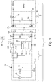
- the Figure 1 shows in a highly schematic representation an arrangement 1 with a charging station 2 and a consumer 3, here a robot.
- the consumer 3 is designed as a mobile consumer 3, which can move automatically.
- the consumer 3 has a driving device (not shown) which comprises, for example, driven wheels.
- the consumer 3 is designed, for example, as a vacuum cleaner robot or as a robotic lawnmower, but can also be implemented as a flight robot.
- the charging station 2 is designed as a base station for the consumer 3 and makes it possible to charge the consumer 3 with electrical current.
- the charging station 2 has a charging interface 4 and the consumer 3 has a counter interface 5, which can be coupled to one another by means of electrical contacting, ie making contact.
- the charging station 2 has electrodes 6 a, b in the charging interface 4, the consumer 3 has counter electrodes 7 a, b in the counter interface 5.
- the electrode 6 a with the counter electrode 7 a and the electrode 6 b with the counter electrode 7 b are contacted.
- the charging station 2 has a supply device 8 which, in order to provide a charging voltage UL and a charging current I, comprises a switched-mode power supply 9 which provides a DC voltage of 19 V, for example.
- a capacitor C1 is provided for smoothing.
- the supply device 8 supplies the charging interface 4 or the electrodes 6 a, b with the charging voltage and / or with the charging current 1.
- a constant charging current is preferably supplied for charging a rechargeable battery, so in this operating case the supply device 8 is preferably a constant current source.
- the corresponding charging method is known to the person skilled in the art as CC (constant current) charging.
- the charging station 2 or the supply device 8 can be set to a charging state, the charging interface 4 being supplied with the charging voltage and optionally additionally with the charging current 1.
- the supply device 8 can also be set to a non-charging state, the charging voltage and / or the charging current 1 not being present at the charging interface 4.
- the switching between the charge state and the non-charge state is implemented by a separating device 10, which is arranged between the supply device 8 and the charging interface 4, in particular the electrode 6 a.
- the separating device 10 is implemented in the exemplary embodiment as a controllable switching element.
- a load resistor 12 (also referred to as "R1") is arranged, via which the electrodes 6 a, b are in particular inseparably and / or permanently connected.
- the load resistor 12 has a resistance of 100 K ⁇ in this embodiment.
- the charging station 2 has a detection device 11 which as the voltage drop across the load resistor 12 or between the electrodes 6a, b or the voltage drop or the voltage U (between the potentials V + and V-, here GND) as one measures electrical quantity G or detection quantity.
- the charging station 2 has an optional charging current test device 14, which taps or detects the charging current I of the supply device 8 flowing via the charging interface 4.
- the detection device 11 is connected to the charging current testing device 14 in terms of signal technology or circuitry, so that the charging current I is detected by the detection device 11.
- the charging current test device 14 is implemented, for example, as a shunt or a galvanically isolated Hall sensor.
- the charging current I is tapped between the supply device 8 and the separating device 10, the voltage U dropping across the load resistor 12 is tapped between the separating device 10 and the charging interface 4.
- the charging station 2 has a control device 16 which can form an integral part of the detection device 11 or is designed as a separate component and is connected to the latter in terms of signal technology.
- the control device 16 controls the separating device 10 in order to switch the supply device 8 or the charging station 2 between the charging state and the non-charging state.
- the consumer 3 has a charging device 17 and an energy store 18, such as. B. a rechargeable battery, with the charging device 17 being arranged electrically between the counter interface 5 and the energy store 18, so that the charging current I is guided from the counter interface 5 to the energy store 18. Furthermore, the charging device 17 has a blocking diode 19 which is connected between the counter electrode 7a and the energy store 18 in order to prevent a return current from the energy store 18 to the counter interface 5.
- an energy store 18 such as. B. a rechargeable battery
- the arrangement 1, in particular the charging station 2 can detect a coupling or docking of the consumer 3 to the charging station 2, the counter interface 5 making electrical contact with the charging interface 4.
- the supply device 8 is set into a non-charging state via the detection device 11 and / or the control device 16 by opening the separating device 10.
- An impedance measurement is carried out in the time domain for detection.
- the impulse response of the system or the arrangement 1 at the charging electrodes 6a, b is measured periodically.
- a short stimulation pulse 20 (duration, for example 0.2 ms) is periodically applied to the charging electrodes 6a, b as a test signal 13 from a voltage source 28.
- the switching element in the isolating device 10, here a MOSFET is briefly activated.
- the voltage source 28 is thus formed here by the switching power supply 9.
- a test signal generator 29 is implemented by the interaction of the switching power supply 9, the isolating device 10 and the control device 16 which controls it and is symbolic in FIG Figure 1 shown.
- Fig. 2 shows a pulse diagram (four individual diagrams, each plotted over time t), which explains the mode of operation of the detection.
- the activation of the switching element or the isolating device 10 gate voltage at the MOSFET.
- the voltage curve of the voltage U applied to the charging electrodes 6a, b and measurable there once with exposed electrodes 6a, b ( Fig. 2b ), once with a (high-resistance) ohmic short circuit ( Fig. 2c ) of the electrodes 6a, b and finally with the consumer attached to the electrodes 6a, b ( Fig. 2d ).
- the MOSFET is turned on and the charging voltage is applied as a voltage U for a short time (until the transition to low L) to the charging electrodes 6a, b . Then, when the electrodes 6a, b are idle, the full charging voltage UL can be measured as the voltage U during the pulse duration tp of the stimulation pulse ( Fig. 2b ).
- the signal curve will be similar, but the amplitude of the signal is usually significantly lower than the charging voltage UL up to almost zero in the case of a full (very low-resistance) short circuit ( Fig. 2c ).
- a capacitor C3 becomes noticeable as its decisive input capacitance, which is connected in the consumer 3 between its counter electrodes 7a, b.
- the voltage U between the electrodes 6a, b will rise somewhat longer or slower than in the case of the stimulus or stimulation pulse 20 due to the charging of the capacitor C3 Figures 2b, c (as in the form of an RC charging curve 25) and then remain constant for the rest of the pulse duration tp (for example approximately at the value of the charging voltage UL).
- the capacitor C3 is slowly discharged via the load resistor 12 or R1. This results in the typical exponential discharge curve 25 of an RC combination, which runs asymptotically towards zero, as the voltage profile.
- a capacitive element here the consumer 3 with its input circuit or the capacitance C3, must be present at the electrodes 6a, b, since a short circuit ( Fig. 2c ) has basically no significant capacitive component.
- the load resistor 12 or R1 can optionally be omitted, since a (rapid) discharge of the capacitance C3 is not necessarily required for the measurement. Without load resistor 12 or R1, however, the measurement is very high-resistance and is therefore sensitive to electrostatic charging of the charging interface 4, as can easily occur especially in the case of synthetic fiber carpets near the floor.
- the stimulation pulses 20 can be applied to the charging electrodes 6a, b at short intervals (e.g. less than 100ms, e.g. 30ms) in order to e.g. B. to charge the charging voltage UL in good time to a consumer 3 that automatically drives onto the charging station 2 before the consumer 3 loses contact with the charging electrodes 6a, b.
- short intervals e.g. less than 100ms, e.g. 30ms
- the charging voltage UL (disconnecting device 10 opened) is interrupted from time to time (for example every few seconds) and the detection method is then carried out again during the interruption.
- a dedicated stimulus pulse 20 during the interruption is superfluous since the charging voltage UL was applied to the electrodes 6a, b and charged the capacitor C3 immediately before the interruption. This results in the falling edge 24 of the stimulation pulse 20.
- the charging current I can also be measured and monitored in order to prevent an interruption in the charging process that is disadvantageous with regard to the rechargeable battery or energy store 18.
- the present one can also be combined with a passive detection method (see above).
- a passive detection method for recognizing the autonomous docking of the robot or consumer 3, but can nevertheless, but then at a significantly reduced speed, also use a robot or consumer 3 from the battery management system by means of the impedance measurement in the time domain BMS switched off battery, which the user on the base station, d. H. Charging station 2, is recognized and charged.
- a passive measurement is carried out continuously every millisecond during docking detection. Every few seconds (in the example shown, every 3 s), the passive measurement is briefly interrupted and a stimulus pulse 20 is applied and, as described above, the impulse response (voltage U) is measured briefly after the time ⁇ t etc.
- the charging current I is monitored via the detection device 11. As soon as the charging current l falls below a predetermined value, the consumer 3 is optionally undocked from the charging station 2 or a completion of the charging process. In order to be able to distinguish between these two states, on the one hand the separating device 10 can be opened and the detection can be carried out again in order to check whether the consumer 3 is still docked at the charging station 2.
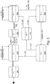
- FIG. 3 A state diagram for monitoring the method for detecting the consumer 3 in the charging station 2 is shown:
- the symbol “10: -” means that the separating device 10 is open and “10: +” that the separating device 10 is closed.
- charging takes place with a constant current I of 2.2 A to 2.5 A.
- the switched-mode power supply 9 is designed as a constant current source.
- a charging current and / or a charging voltage is provided by the supply device 8 for initialization, but at the same time the separating device 10 ( Figure 2 : 10: -) opened so that the charging interface 4 is de-energized on the part of the charging station 2.
- Figure 3 thus represents the combination of the active method in the time domain with the passive method with leakage current measurement (as described in the parallel patent application, see above).
- the control device 16 closes the separation device 10 in a step 300 ( Figure 2 : 10: +), so that a charging voltage is present at the charging interface 4 and a charging current can flow.
- the supply device 8 is set to the charging state.
- this predeterminable fixed time with the charging voltage applied serves, on the one hand, to give the consumer 3, who has docked to the charging station 2, sufficient time to initiate the charging process, and on the other hand, the consumer 3, who tried to dock while doing so triggered the consumer detection, but did not stop in time and ran over the charging interface 4 to create better conditions for the next attempt to dock.
- a step 400 the charging process takes place or is continued.
- a stimulation pulse 20 can be applied again.
- the undocking detection takes place via the stimulation pulse 20 and the load resistance 12, the separating device 10 being opened by the control device 16 and / or the detection device 11 ( Figure 2 : 10: -) and the voltage drop U across the load resistor 12 is detected by the detection device 11.
- step 500 the voltage drop U is above the predeterminable value, in this example 2 V
- the separation device 10 is closed again in a step 700 by the detection device 11 and / or control device 16 and a charging current measurement is carried out by the charging current testing device 14 and the detection device 11. If the charging current I is above the predeterminable value, in this case 2 A, is returned to step 400. In the event that the charging current is below the predeterminable value, a return is made to step 500.
- step 600 In the event that the voltage drop U is below the predeterminable value in step 600, it is assumed that the consumer 3 has been uncoupled or undocked from the charging station 2, and the process returns to step 200.
- a measurement in the frequency domain is alternatively possible.
- the microcontroller additionally has a pulse input EC which is connected to a frequency counter 15.
- Fig. 4 shown circuit required.
- the circuit is greatly simplified, in particular the power supply lines and start and stop signals have not been shown. It is an oscillator circuit that outputs a rectangular output signal.
- the core is a parallel resonant circuit 26 (framed by dashed lines) formed by the capacitor C10 and the coil L10.
- the value of the capacitor C10 should be in the order of magnitude of the expected consumer capacitance (of the capacitor C3). B. at 33 nF and L10 should then be chosen so that the resonant frequency of the resonant circuit is between 30 kHz and 500 kHz.
- the oscillator circuit is excited by the first comparator K1 via the feedback resistors R10 and R11 to oscillate at its own resonant frequency fR.
- a comparator K1 with complementary outputs is used in the example.
- Such comparator ICs are known, for example, as Linear Technology IC LT1713 / LT1714.
- the downstream (second) comparator stage K2 only serves to convert the oscillator signal into a clean square-wave signal, which is then fed to the frequency counter 15 (via the pulse input EC).
- the reference level for this second comparator of the comparator stage K2 is generated by the resistors R12 and R13. Via the coupling or coupling capacitors C11 and C12, the resonant circuit with the in Fig.
- connection points VA, VB connection points VA, VB.
- the charging electrodes 6a, b are therefore AC parallel to the parallel resonant circuit 26, while the coupling capacitors C11, 12 also provide electrical isolation.
- the capacitance values of the coupling capacitors C11, 12 should be large compared to the value of the capacitor C10, that is to say 2.2 ⁇ F in this example. Unipolar ceramic capacitors are preferred.
- the capacitance measurement itself can or may only take place when the switching element is open in the isolating device 10; when the switching element is closed, the circuit would be off Fig. 4 in the direction of the connection points V1, B, namely primarily "see” the very large smoothing capacitor C1 and cannot measure the additional contribution of the consumer capacity (capacitor) C3.
- the capacitor C1 could be decoupled from it by means of a choke, but that would be very complex in the specified frequency range. With this method, this also automatically results in a "self-holding effect" as described previously for the time domain measurement. Only this time, the charging voltage UL itself does not interfere, but the smoothing capacitor C1.
- the frequency counting can be carried out simply by the controlling microcontroller, that is to say the detection device 11 itself.
- the output of the comparator stage K2 ie the pulse input EC
- the pulse input EC is connected to a pulse input of the microcontroller or the detection device 11, which is connected internally to a counter stage. If you first reset the counter and then let it run for a predefined time, it will register all impulses at the pulse input EC and after the predefined time the counter reading is proportional to the current oscillation frequency or oscillation frequency fa of the oscillating circuit 26 as size G.
- the coupling capacitors C11 and C12 have de facto no influence, since the parasitic capacitance between the charging electrodes 6a, b will at most be a few pF.
- the capacitance C3 lies in series with the coupling capacitances C11 and C12 parallel to the resonant circuit capacitor C10. Since C11 and C12 are significantly larger than C3, the value of C3 will dominate the series connection of the three capacitors C11, C3 and C12. Consequently, when the consumer3 is docked, it is de facto C3 parallel to the resonant circuit capacitance C10.
- the oscillation frequency fa of the oscillating circuit 26 is significantly, but not drastically, reduced compared to the resonance frequency fR. The reduction in frequency fa can easily be evaluated with the aid of the connected frequency counter 15.
- Another possibility of determining the possible capacitive impedance of the system at the charging electrodes 6a, b is to couple galvanically decoupled AC signals of low amplitude with different frequencies to the charging electrodes 6a, b and then the to measure current flowing through one of the electrodes 6a, b.
- the current flow must be frequency-dependent due to the consumer capacitance C3, but not when there is a short circuit.
Landscapes
- Engineering & Computer Science (AREA)
- Power Engineering (AREA)
- Physics & Mathematics (AREA)
- General Physics & Mathematics (AREA)
- Charge And Discharge Circuits For Batteries Or The Like (AREA)
Applications Claiming Priority (1)
| Application Number | Priority Date | Filing Date | Title |
|---|---|---|---|
| DE102018214450.8A DE102018214450B4 (de) | 2018-08-27 | 2018-08-27 | Impedanzerkennung eines Verbrauchers an einer Ladestation |
Publications (2)
| Publication Number | Publication Date |
|---|---|
| EP3617721A1 true EP3617721A1 (fr) | 2020-03-04 |
| EP3617721B1 EP3617721B1 (fr) | 2023-03-15 |
Family
ID=67742270
Family Applications (1)
| Application Number | Title | Priority Date | Filing Date |
|---|---|---|---|
| EP19193371.2A Active EP3617721B1 (fr) | 2018-08-27 | 2019-08-23 | Reconnaissance d'impédance d'un consommateur d'une station de charge |
Country Status (2)
| Country | Link |
|---|---|
| EP (1) | EP3617721B1 (fr) |
| DE (1) | DE102018214450B4 (fr) |
Cited By (1)
| Publication number | Priority date | Publication date | Assignee | Title |
|---|---|---|---|---|
| US11613184B1 (en) | 2021-10-31 | 2023-03-28 | Beta Air, Llc | Systems and methods for disabling an electric vehicle during charging |
Citations (5)
| Publication number | Priority date | Publication date | Assignee | Title |
|---|---|---|---|---|
| EP1921523A2 (fr) | 2004-01-21 | 2008-05-14 | IRobot Corporation | Procédé d'acceuil d'un robot autonome |
| DE102010042227A1 (de) | 2010-10-08 | 2012-04-12 | Robert Bosch Gmbh | Verfahren und Ladestation zum elektrischen Aufladen eines elektrischen Energiespeichers |
| EP2648307A1 (fr) | 2010-11-30 | 2013-10-09 | Positec Power Tools (Suzhou) Co., Ltd | Dispositif de marche automatique, poste de charge, système de connexion et procédé de connexion |
| EP2733860A1 (fr) | 2011-07-13 | 2014-05-21 | Sumitomo Electric Industries, Ltd. | Système de communication |
| GB2555939A (en) * | 2016-09-30 | 2018-05-16 | Bae Systems Plc | Electrical power supply system |
-
2018
- 2018-08-27 DE DE102018214450.8A patent/DE102018214450B4/de active Active
-
2019
- 2019-08-23 EP EP19193371.2A patent/EP3617721B1/fr active Active
Patent Citations (5)
| Publication number | Priority date | Publication date | Assignee | Title |
|---|---|---|---|---|
| EP1921523A2 (fr) | 2004-01-21 | 2008-05-14 | IRobot Corporation | Procédé d'acceuil d'un robot autonome |
| DE102010042227A1 (de) | 2010-10-08 | 2012-04-12 | Robert Bosch Gmbh | Verfahren und Ladestation zum elektrischen Aufladen eines elektrischen Energiespeichers |
| EP2648307A1 (fr) | 2010-11-30 | 2013-10-09 | Positec Power Tools (Suzhou) Co., Ltd | Dispositif de marche automatique, poste de charge, système de connexion et procédé de connexion |
| EP2733860A1 (fr) | 2011-07-13 | 2014-05-21 | Sumitomo Electric Industries, Ltd. | Système de communication |
| GB2555939A (en) * | 2016-09-30 | 2018-05-16 | Bae Systems Plc | Electrical power supply system |
Cited By (2)
| Publication number | Priority date | Publication date | Assignee | Title |
|---|---|---|---|---|
| US11613184B1 (en) | 2021-10-31 | 2023-03-28 | Beta Air, Llc | Systems and methods for disabling an electric vehicle during charging |
| US12043129B2 (en) | 2021-10-31 | 2024-07-23 | Beta Air, Llc | Systems and methods for disabling an electric vehicle during charging |
Also Published As
| Publication number | Publication date |
|---|---|
| DE102018214450B4 (de) | 2024-12-05 |
| EP3617721B1 (fr) | 2023-03-15 |
| DE102018214450A1 (de) | 2020-02-27 |
Similar Documents
| Publication | Publication Date | Title |
|---|---|---|
| EP2613683B1 (fr) | Dispositif et procédé pour détecter un changement d'état de fonctionnement d'un outil électrique ainsi qu'un aspirateur | |
| EP3616976B1 (fr) | Station de charge pour un consommateur, dispositif comprenant le consommateur et la station de charge ainsi que procédé | |
| EP2625763B1 (fr) | Procédé et station de charge pour la charge électrique d'un accumulateur d'énergie électrique | |
| DE102016122115B3 (de) | Schaltzustand eines mechanischen schalters | |
| EP2570289B1 (fr) | Dispositif de détection de la résistance de l'isolement d'un système de batterie haute tension | |
| EP3479745B1 (fr) | Procédé de fonctionnement d'un entraînement électrique, de préférence d'un ventilateur et / ou d'une brosse d'un aspirateur ou d'un aspirateur robot | |
| EP4377122B1 (fr) | Dispositif de sécurité pour un réseau électrique à courant continu, système électrique embarqué pour un véhicule, véhicule et borne de recharge à courant continu | |
| EP3162266B1 (fr) | Appareil de nettoyage et procédé pour utiliser l'appareil de nettoyage | |
| DE102017215889A1 (de) | Spannungs-Erfassungs-Vorrichtung | |
| DE112019002395T5 (de) | Wiederaufladbare reinigungsvorrichtung | |
| DE202012013720U1 (de) | Kommunikationsmodul für Ladegeräte von Elektrofahrzeugen | |
| WO2020094548A1 (fr) | Dispositif de protection contre la remise sous tension | |
| WO2022008640A1 (fr) | Technique de surveillance d'un contact entre des conducteurs de charge pour charger un véhicule électrique | |
| DE102018221479A1 (de) | Schaltungsanordnung zur Fehlererkennung in einem ungeerdeten Hochvoltsystem | |
| EP3617721B1 (fr) | Reconnaissance d'impédance d'un consommateur d'une station de charge | |
| WO2013029774A2 (fr) | Procédé et dispositif permettant de charger un accumulateur d'énergie dans un véhicule | |
| DE102017213357B3 (de) | Verfahren und Vorrichtung zur Erdungswiderstanderkennung in einem Ladekabel | |
| EP1226474A2 (fr) | Dispositif de detection d'une coupure de courant dans un appareil domestique | |
| DE102010030959A1 (de) | Sensoreinrichtung und Verfahren zur Detektion eines Umgreifens eines Handgerätes sowie ein Handgerät | |
| WO2020120557A1 (fr) | Système pour un véhicule | |
| DE102021003884A1 (de) | Schutzvorrichtung für ein elektrisches Gleichstromnetz | |
| DE102021003850A1 (de) | Hochvoltbordnetz für ein Fahrzeug | |
| EP2315338B1 (fr) | Agencement de commutation (à l'arrêt) destiné au fonctionnement d'un appareil ménager et procédé correspondant | |
| DE10309143B4 (de) | Sensoreinrichtung an einer unter hoher Spannung stehenden Förderleitung | |
| EP2315337B1 (fr) | Appareil ménager et procédé de fonctionnement d'un appareil ménager |
Legal Events
| Date | Code | Title | Description |
|---|---|---|---|
| PUAI | Public reference made under article 153(3) epc to a published international application that has entered the european phase |
Free format text: ORIGINAL CODE: 0009012 |
|
| STAA | Information on the status of an ep patent application or granted ep patent |
Free format text: STATUS: THE APPLICATION HAS BEEN PUBLISHED |
|
| AK | Designated contracting states |
Kind code of ref document: A1 Designated state(s): AL AT BE BG CH CY CZ DE DK EE ES FI FR GB GR HR HU IE IS IT LI LT LU LV MC MK MT NL NO PL PT RO RS SE SI SK SM TR |
|
| AX | Request for extension of the european patent |
Extension state: BA ME |
|
| STAA | Information on the status of an ep patent application or granted ep patent |
Free format text: STATUS: REQUEST FOR EXAMINATION WAS MADE |
|
| 17P | Request for examination filed |
Effective date: 20200904 |
|
| RBV | Designated contracting states (corrected) |
Designated state(s): AL AT BE BG CH CY CZ DE DK EE ES FI FR GB GR HR HU IE IS IT LI LT LU LV MC MK MT NL NO PL PT RO RS SE SI SK SM TR |
|
| GRAP | Despatch of communication of intention to grant a patent |
Free format text: ORIGINAL CODE: EPIDOSNIGR1 |
|
| STAA | Information on the status of an ep patent application or granted ep patent |
Free format text: STATUS: GRANT OF PATENT IS INTENDED |
|
| INTG | Intention to grant announced |
Effective date: 20221104 |
|
| GRAS | Grant fee paid |
Free format text: ORIGINAL CODE: EPIDOSNIGR3 |
|
| GRAA | (expected) grant |
Free format text: ORIGINAL CODE: 0009210 |
|
| STAA | Information on the status of an ep patent application or granted ep patent |
Free format text: STATUS: THE PATENT HAS BEEN GRANTED |
|
| AK | Designated contracting states |
Kind code of ref document: B1 Designated state(s): AL AT BE BG CH CY CZ DE DK EE ES FI FR GB GR HR HU IE IS IT LI LT LU LV MC MK MT NL NO PL PT RO RS SE SI SK SM TR |
|
| REG | Reference to a national code |
Ref country code: CH Ref legal event code: EP Ref country code: GB Ref legal event code: FG4D Free format text: NOT ENGLISH |
|
| REG | Reference to a national code |
Ref country code: DE Ref legal event code: R096 Ref document number: 502019007200 Country of ref document: DE |
|
| REG | Reference to a national code |
Ref country code: IE Ref legal event code: FG4D Free format text: LANGUAGE OF EP DOCUMENT: GERMAN |
|
| REG | Reference to a national code |
Ref country code: AT Ref legal event code: REF Ref document number: 1554302 Country of ref document: AT Kind code of ref document: T Effective date: 20230415 |
|
| REG | Reference to a national code |
Ref country code: LT Ref legal event code: MG9D |
|
| REG | Reference to a national code |
Ref country code: NL Ref legal event code: MP Effective date: 20230315 |
|
| PG25 | Lapsed in a contracting state [announced via postgrant information from national office to epo] |
Ref country code: RS Free format text: LAPSE BECAUSE OF FAILURE TO SUBMIT A TRANSLATION OF THE DESCRIPTION OR TO PAY THE FEE WITHIN THE PRESCRIBED TIME-LIMIT Effective date: 20230315 Ref country code: NO Free format text: LAPSE BECAUSE OF FAILURE TO SUBMIT A TRANSLATION OF THE DESCRIPTION OR TO PAY THE FEE WITHIN THE PRESCRIBED TIME-LIMIT Effective date: 20230615 Ref country code: LV Free format text: LAPSE BECAUSE OF FAILURE TO SUBMIT A TRANSLATION OF THE DESCRIPTION OR TO PAY THE FEE WITHIN THE PRESCRIBED TIME-LIMIT Effective date: 20230315 Ref country code: LT Free format text: LAPSE BECAUSE OF FAILURE TO SUBMIT A TRANSLATION OF THE DESCRIPTION OR TO PAY THE FEE WITHIN THE PRESCRIBED TIME-LIMIT Effective date: 20230315 Ref country code: HR Free format text: LAPSE BECAUSE OF FAILURE TO SUBMIT A TRANSLATION OF THE DESCRIPTION OR TO PAY THE FEE WITHIN THE PRESCRIBED TIME-LIMIT Effective date: 20230315 |
|
| PG25 | Lapsed in a contracting state [announced via postgrant information from national office to epo] |
Ref country code: SE Free format text: LAPSE BECAUSE OF FAILURE TO SUBMIT A TRANSLATION OF THE DESCRIPTION OR TO PAY THE FEE WITHIN THE PRESCRIBED TIME-LIMIT Effective date: 20230315 Ref country code: NL Free format text: LAPSE BECAUSE OF FAILURE TO SUBMIT A TRANSLATION OF THE DESCRIPTION OR TO PAY THE FEE WITHIN THE PRESCRIBED TIME-LIMIT Effective date: 20230315 Ref country code: GR Free format text: LAPSE BECAUSE OF FAILURE TO SUBMIT A TRANSLATION OF THE DESCRIPTION OR TO PAY THE FEE WITHIN THE PRESCRIBED TIME-LIMIT Effective date: 20230616 Ref country code: FI Free format text: LAPSE BECAUSE OF FAILURE TO SUBMIT A TRANSLATION OF THE DESCRIPTION OR TO PAY THE FEE WITHIN THE PRESCRIBED TIME-LIMIT Effective date: 20230315 |
|
| PG25 | Lapsed in a contracting state [announced via postgrant information from national office to epo] |
Ref country code: SM Free format text: LAPSE BECAUSE OF FAILURE TO SUBMIT A TRANSLATION OF THE DESCRIPTION OR TO PAY THE FEE WITHIN THE PRESCRIBED TIME-LIMIT Effective date: 20230315 Ref country code: RO Free format text: LAPSE BECAUSE OF FAILURE TO SUBMIT A TRANSLATION OF THE DESCRIPTION OR TO PAY THE FEE WITHIN THE PRESCRIBED TIME-LIMIT Effective date: 20230315 Ref country code: PT Free format text: LAPSE BECAUSE OF FAILURE TO SUBMIT A TRANSLATION OF THE DESCRIPTION OR TO PAY THE FEE WITHIN THE PRESCRIBED TIME-LIMIT Effective date: 20230717 Ref country code: ES Free format text: LAPSE BECAUSE OF FAILURE TO SUBMIT A TRANSLATION OF THE DESCRIPTION OR TO PAY THE FEE WITHIN THE PRESCRIBED TIME-LIMIT Effective date: 20230315 Ref country code: EE Free format text: LAPSE BECAUSE OF FAILURE TO SUBMIT A TRANSLATION OF THE DESCRIPTION OR TO PAY THE FEE WITHIN THE PRESCRIBED TIME-LIMIT Effective date: 20230315 Ref country code: CZ Free format text: LAPSE BECAUSE OF FAILURE TO SUBMIT A TRANSLATION OF THE DESCRIPTION OR TO PAY THE FEE WITHIN THE PRESCRIBED TIME-LIMIT Effective date: 20230315 |
|
| PG25 | Lapsed in a contracting state [announced via postgrant information from national office to epo] |
Ref country code: SK Free format text: LAPSE BECAUSE OF FAILURE TO SUBMIT A TRANSLATION OF THE DESCRIPTION OR TO PAY THE FEE WITHIN THE PRESCRIBED TIME-LIMIT Effective date: 20230315 Ref country code: PL Free format text: LAPSE BECAUSE OF FAILURE TO SUBMIT A TRANSLATION OF THE DESCRIPTION OR TO PAY THE FEE WITHIN THE PRESCRIBED TIME-LIMIT Effective date: 20230315 Ref country code: IS Free format text: LAPSE BECAUSE OF FAILURE TO SUBMIT A TRANSLATION OF THE DESCRIPTION OR TO PAY THE FEE WITHIN THE PRESCRIBED TIME-LIMIT Effective date: 20230715 |
|
| REG | Reference to a national code |
Ref country code: DE Ref legal event code: R097 Ref document number: 502019007200 Country of ref document: DE |
|
| PLBE | No opposition filed within time limit |
Free format text: ORIGINAL CODE: 0009261 |
|
| STAA | Information on the status of an ep patent application or granted ep patent |
Free format text: STATUS: NO OPPOSITION FILED WITHIN TIME LIMIT |
|
| PG25 | Lapsed in a contracting state [announced via postgrant information from national office to epo] |
Ref country code: SI Free format text: LAPSE BECAUSE OF FAILURE TO SUBMIT A TRANSLATION OF THE DESCRIPTION OR TO PAY THE FEE WITHIN THE PRESCRIBED TIME-LIMIT Effective date: 20230315 Ref country code: DK Free format text: LAPSE BECAUSE OF FAILURE TO SUBMIT A TRANSLATION OF THE DESCRIPTION OR TO PAY THE FEE WITHIN THE PRESCRIBED TIME-LIMIT Effective date: 20230315 |
|
| 26N | No opposition filed |
Effective date: 20231218 |
|
| PG25 | Lapsed in a contracting state [announced via postgrant information from national office to epo] |
Ref country code: MC Free format text: LAPSE BECAUSE OF FAILURE TO SUBMIT A TRANSLATION OF THE DESCRIPTION OR TO PAY THE FEE WITHIN THE PRESCRIBED TIME-LIMIT Effective date: 20230315 |
|
| REG | Reference to a national code |
Ref country code: CH Ref legal event code: PL |
|
| PG25 | Lapsed in a contracting state [announced via postgrant information from national office to epo] |
Ref country code: MC Free format text: LAPSE BECAUSE OF FAILURE TO SUBMIT A TRANSLATION OF THE DESCRIPTION OR TO PAY THE FEE WITHIN THE PRESCRIBED TIME-LIMIT Effective date: 20230315 |
|
| PG25 | Lapsed in a contracting state [announced via postgrant information from national office to epo] |
Ref country code: LU Free format text: LAPSE BECAUSE OF NON-PAYMENT OF DUE FEES Effective date: 20230823 |
|
| PG25 | Lapsed in a contracting state [announced via postgrant information from national office to epo] |
Ref country code: LU Free format text: LAPSE BECAUSE OF NON-PAYMENT OF DUE FEES Effective date: 20230823 Ref country code: CH Free format text: LAPSE BECAUSE OF NON-PAYMENT OF DUE FEES Effective date: 20230831 |
|
| REG | Reference to a national code |
Ref country code: BE Ref legal event code: MM Effective date: 20230831 |
|
| REG | Reference to a national code |
Ref country code: IE Ref legal event code: MM4A |
|
| PG25 | Lapsed in a contracting state [announced via postgrant information from national office to epo] |
Ref country code: IT Free format text: LAPSE BECAUSE OF FAILURE TO SUBMIT A TRANSLATION OF THE DESCRIPTION OR TO PAY THE FEE WITHIN THE PRESCRIBED TIME-LIMIT Effective date: 20230315 |
|
| PG25 | Lapsed in a contracting state [announced via postgrant information from national office to epo] |
Ref country code: IE Free format text: LAPSE BECAUSE OF NON-PAYMENT OF DUE FEES Effective date: 20230823 |
|
| PG25 | Lapsed in a contracting state [announced via postgrant information from national office to epo] |
Ref country code: IE Free format text: LAPSE BECAUSE OF NON-PAYMENT OF DUE FEES Effective date: 20230823 |
|
| PG25 | Lapsed in a contracting state [announced via postgrant information from national office to epo] |
Ref country code: BE Free format text: LAPSE BECAUSE OF NON-PAYMENT OF DUE FEES Effective date: 20230831 |
|
| PG25 | Lapsed in a contracting state [announced via postgrant information from national office to epo] |
Ref country code: BG Free format text: LAPSE BECAUSE OF FAILURE TO SUBMIT A TRANSLATION OF THE DESCRIPTION OR TO PAY THE FEE WITHIN THE PRESCRIBED TIME-LIMIT Effective date: 20230315 |
|
| PG25 | Lapsed in a contracting state [announced via postgrant information from national office to epo] |
Ref country code: BG Free format text: LAPSE BECAUSE OF FAILURE TO SUBMIT A TRANSLATION OF THE DESCRIPTION OR TO PAY THE FEE WITHIN THE PRESCRIBED TIME-LIMIT Effective date: 20230315 |
|
| PG25 | Lapsed in a contracting state [announced via postgrant information from national office to epo] |
Ref country code: CY Free format text: LAPSE BECAUSE OF FAILURE TO SUBMIT A TRANSLATION OF THE DESCRIPTION OR TO PAY THE FEE WITHIN THE PRESCRIBED TIME-LIMIT; INVALID AB INITIO Effective date: 20190823 |
|
| PG25 | Lapsed in a contracting state [announced via postgrant information from national office to epo] |
Ref country code: HU Free format text: LAPSE BECAUSE OF FAILURE TO SUBMIT A TRANSLATION OF THE DESCRIPTION OR TO PAY THE FEE WITHIN THE PRESCRIBED TIME-LIMIT; INVALID AB INITIO Effective date: 20190823 |
|
| PGFP | Annual fee paid to national office [announced via postgrant information from national office to epo] |
Ref country code: DE Payment date: 20250831 Year of fee payment: 7 |
|
| REG | Reference to a national code |
Ref country code: AT Ref legal event code: MM01 Ref document number: 1554302 Country of ref document: AT Kind code of ref document: T Effective date: 20240823 |
|
| PGFP | Annual fee paid to national office [announced via postgrant information from national office to epo] |
Ref country code: GB Payment date: 20250822 Year of fee payment: 7 |
|
| PG25 | Lapsed in a contracting state [announced via postgrant information from national office to epo] |
Ref country code: AT Free format text: LAPSE BECAUSE OF NON-PAYMENT OF DUE FEES Effective date: 20240823 |
|
| PGFP | Annual fee paid to national office [announced via postgrant information from national office to epo] |
Ref country code: FR Payment date: 20250827 Year of fee payment: 7 |
|
| PG25 | Lapsed in a contracting state [announced via postgrant information from national office to epo] |
Ref country code: TR Free format text: LAPSE BECAUSE OF FAILURE TO SUBMIT A TRANSLATION OF THE DESCRIPTION OR TO PAY THE FEE WITHIN THE PRESCRIBED TIME-LIMIT Effective date: 20230315 |
|
| PGFP | Annual fee paid to national office [announced via postgrant information from national office to epo] |
Ref country code: AT Payment date: 20260410 Year of fee payment: 5 |