EP3617828A1 - Véhicule de traitement de surface autonome à mode de paroi rapide - Google Patents
Véhicule de traitement de surface autonome à mode de paroi rapide Download PDFInfo
- Publication number
- EP3617828A1 EP3617828A1 EP18191058.9A EP18191058A EP3617828A1 EP 3617828 A1 EP3617828 A1 EP 3617828A1 EP 18191058 A EP18191058 A EP 18191058A EP 3617828 A1 EP3617828 A1 EP 3617828A1
- Authority
- EP
- European Patent Office
- Prior art keywords
- safety
- speed
- safety zone
- surface treatment
- treatment vehicle
- Prior art date
- Legal status (The legal status is an assumption and is not a legal conclusion. Google has not performed a legal analysis and makes no representation as to the accuracy of the status listed.)
- Withdrawn
Links
- 238000004381 surface treatment Methods 0.000 title claims abstract description 60
- 238000001514 detection method Methods 0.000 claims abstract description 17
- 238000004140 cleaning Methods 0.000 claims description 23
- 230000004044 response Effects 0.000 claims description 18
- 230000007246 mechanism Effects 0.000 claims description 17
- 230000008859 change Effects 0.000 claims description 13
- 238000000034 method Methods 0.000 claims description 12
- 238000010408 sweeping Methods 0.000 claims description 6
- 238000005498 polishing Methods 0.000 claims description 5
- 238000005201 scrubbing Methods 0.000 claims description 5
- 239000003599 detergent Substances 0.000 claims description 3
- 239000000843 powder Substances 0.000 claims description 3
- 238000007789 sealing Methods 0.000 claims description 3
- 239000007788 liquid Substances 0.000 description 4
- 238000013461 design Methods 0.000 description 3
- 238000010586 diagram Methods 0.000 description 3
- 238000000926 separation method Methods 0.000 description 2
- 238000012795 verification Methods 0.000 description 2
- 238000005406 washing Methods 0.000 description 2
- 241000894006 Bacteria Species 0.000 description 1
- 241001417527 Pempheridae Species 0.000 description 1
- 230000001133 acceleration Effects 0.000 description 1
- 230000009471 action Effects 0.000 description 1
- 238000013459 approach Methods 0.000 description 1
- 238000012937 correction Methods 0.000 description 1
- 230000001934 delay Effects 0.000 description 1
- 230000001419 dependent effect Effects 0.000 description 1
- 230000000249 desinfective effect Effects 0.000 description 1
- 238000001035 drying Methods 0.000 description 1
- 239000000428 dust Substances 0.000 description 1
- 238000005516 engineering process Methods 0.000 description 1
- 239000012530 fluid Substances 0.000 description 1
- 230000004807 localization Effects 0.000 description 1
- 238000013507 mapping Methods 0.000 description 1
- 238000005457 optimization Methods 0.000 description 1
- 239000002245 particle Substances 0.000 description 1
- 230000008569 process Effects 0.000 description 1
- 230000008672 reprogramming Effects 0.000 description 1
- 239000007787 solid Substances 0.000 description 1
- 238000005507 spraying Methods 0.000 description 1
- 238000004659 sterilization and disinfection Methods 0.000 description 1
- 239000000126 substance Substances 0.000 description 1
- XLYOFNOQVPJJNP-UHFFFAOYSA-N water Substances O XLYOFNOQVPJJNP-UHFFFAOYSA-N 0.000 description 1
Images


Classifications
-
- G—PHYSICS
- G05—CONTROLLING; REGULATING
- G05D—SYSTEMS FOR CONTROLLING OR REGULATING NON-ELECTRIC VARIABLES
- G05D1/00—Control of position, course, altitude or attitude of land, water, air or space vehicles, e.g. using automatic pilots
- G05D1/60—Intended control result
- G05D1/617—Safety or protection, e.g. defining protection zones around obstacles or avoiding hazards
-
- G—PHYSICS
- G05—CONTROLLING; REGULATING
- G05D—SYSTEMS FOR CONTROLLING OR REGULATING NON-ELECTRIC VARIABLES
- G05D1/00—Control of position, course, altitude or attitude of land, water, air or space vehicles, e.g. using automatic pilots
- G05D1/02—Control of position or course in two dimensions
- G05D1/021—Control of position or course in two dimensions specially adapted to land vehicles
- G05D1/0231—Control of position or course in two dimensions specially adapted to land vehicles using optical position detecting means
- G05D1/0238—Control of position or course in two dimensions specially adapted to land vehicles using optical position detecting means using obstacle or wall sensors
- G05D1/024—Control of position or course in two dimensions specially adapted to land vehicles using optical position detecting means using obstacle or wall sensors in combination with a laser
-
- G—PHYSICS
- G05—CONTROLLING; REGULATING
- G05D—SYSTEMS FOR CONTROLLING OR REGULATING NON-ELECTRIC VARIABLES
- G05D1/00—Control of position, course, altitude or attitude of land, water, air or space vehicles, e.g. using automatic pilots
- G05D1/02—Control of position or course in two dimensions
- G05D1/021—Control of position or course in two dimensions specially adapted to land vehicles
- G05D1/0212—Control of position or course in two dimensions specially adapted to land vehicles with means for defining a desired trajectory
- G05D1/0223—Control of position or course in two dimensions specially adapted to land vehicles with means for defining a desired trajectory involving speed control of the vehicle
-
- G—PHYSICS
- G05—CONTROLLING; REGULATING
- G05D—SYSTEMS FOR CONTROLLING OR REGULATING NON-ELECTRIC VARIABLES
- G05D1/00—Control of position, course, altitude or attitude of land, water, air or space vehicles, e.g. using automatic pilots
- G05D1/02—Control of position or course in two dimensions
- G05D1/021—Control of position or course in two dimensions specially adapted to land vehicles
- G05D1/0268—Control of position or course in two dimensions specially adapted to land vehicles using internal positioning means
- G05D1/0274—Control of position or course in two dimensions specially adapted to land vehicles using internal positioning means using mapping information stored in a memory device
-
- G—PHYSICS
- G05—CONTROLLING; REGULATING
- G05D—SYSTEMS FOR CONTROLLING OR REGULATING NON-ELECTRIC VARIABLES
- G05D1/00—Control of position, course, altitude or attitude of land, water, air or space vehicles, e.g. using automatic pilots
- G05D1/20—Control system inputs
- G05D1/24—Arrangements for determining position or orientation
- G05D1/246—Arrangements for determining position or orientation using environment maps, e.g. simultaneous localisation and mapping [SLAM]
-
- G—PHYSICS
- G05—CONTROLLING; REGULATING
- G05D—SYSTEMS FOR CONTROLLING OR REGULATING NON-ELECTRIC VARIABLES
- G05D1/00—Control of position, course, altitude or attitude of land, water, air or space vehicles, e.g. using automatic pilots
- G05D1/20—Control system inputs
- G05D1/24—Arrangements for determining position or orientation
- G05D1/247—Arrangements for determining position or orientation using signals provided by artificial sources external to the vehicle, e.g. navigation beacons
-
- G—PHYSICS
- G05—CONTROLLING; REGULATING
- G05D—SYSTEMS FOR CONTROLLING OR REGULATING NON-ELECTRIC VARIABLES
- G05D1/00—Control of position, course, altitude or attitude of land, water, air or space vehicles, e.g. using automatic pilots
- G05D1/60—Intended control result
- G05D1/65—Following a desired speed profile
-
- G—PHYSICS
- G05—CONTROLLING; REGULATING
- G05D—SYSTEMS FOR CONTROLLING OR REGULATING NON-ELECTRIC VARIABLES
- G05D1/00—Control of position, course, altitude or attitude of land, water, air or space vehicles, e.g. using automatic pilots
- G05D1/80—Arrangements for reacting to or preventing system or operator failure
- G05D1/81—Handing over between on-board automatic and on-board manual control
Definitions
- the present invention relates to the field of autonomous vehicles, specifically to the field of autonomous surface treatment vehicles, such as self driven floor cleaning devices etc. More specifically, the invention provides an autonomous surface treatment vehicle with a safety system allowing e.g. a special wall mode of operation, e.g. allowing increased speed at a given distance to the wall, or shorter distance to the wall at a given speed.
- a safety system allowing e.g. a special wall mode of operation, e.g. allowing increased speed at a given distance to the wall, or shorter distance to the wall at a given speed.
- An autonomous vehicle typically has both an autonomy system for controlling navigation and a safety system.
- the objective of the autonomy system is to enable the vehicle to move around in an environment.
- the navigation system is often implemented with a SLAM (Simultaneous Localization and Mapping) function that is capable of both generating a map of the surroundings and using the generated map to move accurately and precisely around the mapped area.
- the function of the safety system is to ensure the vehicle does not cause harm to people, neither directly nor indirectly.
- the safety system can include protection against surface drop-off, e.g. stairs, ledges or the like, and a proximity protection against bumping into obstacles, e.g. a person or other object.
- the autonomous vehicle must comply with relevant safety operation standards in order to be certified for operation.
- the proximity protection part of the safety implements different safety zones, wherein each safety zone is an area selected by the safety system based on the vehicle speed and direction. Any object or person within a safety zone will cause the vehicle to come to a stop.
- Safety zones are designed of a size and shape to prevent vehicle collision.
- a challenge and optimization problem for the proximity protection part of the safety system is to react quickly and stop when a person or other object enters the safety zone. In the worst-case scenario of maximum direction and speed change, this puts limits to e.g. driving at a short distance along a wall.
- the worst-case safety zone can only be expressed by a balance between a slow speed and a reasonable driving distance to the wall. This can lead to a poor efficiency, e.g. for an autonomous cleaning machine to clean the floor at a short distance to a long wall.
- the size of the safety zone for a given operational speed is impacted by the latency in reacting and the de-acceleration, but especially the change of direction and speed during the latency period.
- safety zone concept is often implemented as selection of pre-stored sets of safety zones calculated based on the characteristics of the vehicle with respect to acceleration/deceleration and direction change capabilities in the latency period.
- the safety system select the corresponding safety zone, e.g. having often the shape of a wedge around the vehicle.
- an autonomous mobile vehicle for treating floors, e.g. a floor washer, a floor sweeper, a floor stripping device or the like, with increased efficiency in floor treatment under various operating conditions and still complying with safety operation standards.
- the invention provides an autonomous mobile surface treatment vehicle for driving on a surface, the surface treatment vehicle comprising
- the special mode of operation can be used for operating conditions that require special attention.
- the first mode of operation can be a "normal” or default mode of operation which is known from the prior art based on safety zones reflecting the worst case requirements.
- the second mode of operation can be a "special" mode of operation which may be requested by the autonomy system when entering special conditions where the another way of selecting safety zone can be advantageous.
- such special mode of operation can be a fast wall mode, where the safety system can assign a special set of pre-calculated safety zone with increased speed but under restriction of a direction which is set to be below the maximum possible direction change in the latency period, i.e. different from the worst case scenario.
- such special mode of operation allows another balance between direction and speed limits, and thus the autonomy system can be programmed so request such special mode, when e.g. approaching a wall.
- This can be utilized by the autonomy system, which can request such wall mode, e.g. when the autonomy system has a planned route approaching a long distance near a wall. At the end of such driving near a wall, approaching a turn, the autonomy system can request to leave the wall mode which would otherwise cause a safety stop due to the necessary direction change for making a turn.
- the invention offers the autonomy system the possibility of requesting a special contract with the safety system regarding speed and direction limits different from the normal worst case mode of operation. This can be advantageous in a given situation, where the autonomy system has a planned route with known special requirements, e.g. driving near a wall etc.
- the safety system electronics from known autonomous vehicles can be reused, only requiring a reprogramming and an electric wired or wireless input to receive an electric request signal from the autonomy system. Also, there is a need to implement a dedicated library of pre-stored safety zones to be selected from in the second mode of operation. In some embodiments, a recertification of the safety system can be required.
- the invention can be implemented on any type of autonomous surface treating vehicle, such as self driven floor cleaning machines of different size and propulsion system.
- the invention is advantageous for large and heavy vehicles designed for high speed driving, since these machines are bound by safety requirements, e.g. CSA 336 covering autonomous battery powered cleaning machines.
- 'surface treatment vehicle' is understood a vehicle comprising equipment capable of performing a treatment of the surface over or on which the vehicles moves.
- Such treatment may especially comprise cleaning and/or mechanical cleaning of the surface.
- cleaning is understood at least cleaning by suction, washing, scrubbing, sweeping, drying, disinfection or otherwise cleaning, discovering, sensing, handling, picking up, removing, disinfecting or clearing away any dust, dirt, debris, particles, liquids, fluids, bacteria or any other substance from the air (or any other gas), water (or any other liquid), or any natural or man-made surface) by any means of manual, electronic, intelligent, autonomous and/or connected cleaning solutions.
- mechanical cleaning is understood at least mechanical cleaning by the processes of scrubbing, polishing, washing and/or sweeping surfaces, using suction power to pick up debris and/or liquids from the surface etc.
- Safety zone an area selected by the safety system based on the vehicle speed and direction. Any object or person within a safety zone will cause the vehicle to come to a stop. Safety zones are designed of a size and shape to prevent vehicle collision.
- the first mode of operation may especially be a normal or default mode of operation, wherein the first safety zone selection algorithm selects safety zone to fulfil worst case requirements during the latency period for a full stop operation, and wherein the second mode of operation is a special mode of operation which can be selected for special operating conditions, where restrictions on possible change of speed and/or direction during the latency period can be guaranteed to be avoided.
- the autonomy system is arranged to send a request signal to the safety system to request said switch from the first to the second mode of operation. It is to be understood that switching to the second mode of operation can alternatively be initiated by other means, e.g. manually by a user.
- the second safety zone selection algorithm is arranged to select the safety zone from a set of pre-stored safety zones where direction is limited compared to a maximum direction change possible by the steering mechanism, hereby allowing e.g. a fast wall mode of operation, since the possible direction change has been limited compared to the worst-case scenario of full left or right direction change in the latency period.
- a symmetric or an asymmetric safety zone can be selected in such wall mode, i.e. where maximum allowable direction change is symmetric or asymmetric, e.g. around a direction straight ahead.
- the asymmetric safety zones could be defined in relation to any driving direction, e.g.
- the second safety zone selection algorithm may be arranged to select a safety zone which allows a higher speed under the restriction of a more narrow direction angle, compared to a safety zone selected by the first safety zone selection algorithm.
- said restriction of a more narrow direction angle is to be determined for the vehicle in question, but in general it is preferred that the narrow direction angle is selected so as to accommodate small direction corrections needed for the vehicle to follow a straight direction without conflicting with the safety zone, which would otherwise cause a safety stop.
- the increased speed near a wall can increase efficiency significantly, e.g. when operating in smaller rooms or in narrow rooms, such as a hotel corridor, where the worst-case safety zone will allow only a very limited speed in average.
- the speed and direction control signals output by the autonomy system are applied to the safety system, and wherein the safety system is arranged to, when being in the second mode of operation:
- the speed and direction control signals from the autonomy system are routed via the safety system, which then filters the speed and direction values and outputs only valid speed and direction signals complying with the special safety zone selected, or alternatively simply skips sending speed and direction signals with values which do not comply with the safety zone requirements.
- a safety stop signal to the controller, in case the speed and direction control signals from the autonomy system conflict with the safety zone, and/or to send a signal to the autonomy signal to inform about the conflict.
- a still further option for the safety system is to automatically switch back to the first mode of operation, in case speed and direction control signals from the autonomy system conflict with the safety zone requirements. It is to be understood, that in this embodiment, it is the responsibility of the autonomy system to handle the second mode of operation by complying with the special speed and direction restrictions of the safety zones selected in the second mode of operation.
- the speed and direction control signals output by the autonomy system are applied to the safety system, and wherein the safety system is arranged to, when being in the special mode of operation:
- the safety system simply monitors the speed and direction control signals from the autonomy system.
- the autonomy system should have pre-stored information regarding the second possibly more modes of operations, so that once requested, the autonomy system knows the speed and direction limit requirements valid for safety zones selected in these modes of operation. If the autonomy system does not send speed and direction control signals complying with the requirements in the second mode of operation, the safety system will preferably be programmed to generate a safety stop signal.
- the safety system is arranged to, when being in the second mode of operation:
- the autonomy can request a curved trajectory mode of operation, e.g. where the autonomy system requests a special safety zone suited for following a direction with a fixed curve.
- the safety system may be arranged to receive data indicative of a planned trajectory from the autonomy system, and when being in the special mode of operation:
- This embodiment is advantageous e.g. when the autonomy system has a planned trajectory to follow, such as for following a curve with a fixed curvature.
- trajectory is understood a path with given restrictions of maximum speed and maximum direction deviations over a period of time.
- the safety system is arranged to send an acknowledge signal to the autonomy system in response to the request signal, so as to communicate that the safety system is in the second mode of operation.
- the autonomy system can take action accordingly, and send speed and direction control signals which do not violate the requirements in the second mode of operation.
- the first safety zone selection algorithm and the second safety zone selection algorithm may be arranged to select a safety zone from two separate sets of pre-stored safety zones.
- the separate sets of pre-stored safety zones are pre-calculated sets of safety zones based on emergency stop time data for the specific surface treatment vehicle.
- the first and second safety zone sets can be off-line calculated and stored as separate tabulated data sets.
- the autonomy system and the safety system are constituted by separate electronic circuits e.g. with separate programmable processors.
- the autonomy system may be arranged to send the request signal to request a special mode of operation to the safety system via a wired electrical connection or via a wireless radio frequency signal.
- the safety system can be implemented by known components, and the separation allows verification of the safety procedures without the autonomy need for verification in case the autonomy system is changed.
- the safety system is arranged to switch the safety zone selection algorithm between the first, the second and one or more safety zone selection algorithms.
- a fast wall mode e.g. a fast wall mode, a very-near wall mode, and a trajectory mode of operation can be selected. If preferred, more than two, such as 3-10 different modes may be selected each with a special set of pre-calculated and pre-stored safety zones.
- the specific safety zone selection algorithm can be requested by sending a request signal to the safety system indicating the specific safety zone selection algorithm.
- the autonomy system can be arranged to send such request signal to the safety system.
- the sensor system may comprises a LIDAR scanner for scanning for obstacles.
- LIDAR scanner for scanning for obstacles.
- other sensor technologies may be used as well for this scanning.
- the surface treatment vehicle has a total mass of at least 50 kg, such as at least 70 kg, such as at least 200 kg, such as at least 600 kg, or even above 600 kg.
- the invention is advantageous.
- the surface treatment vehicle has a maximum speed of at least 3 km/h, such as at least 6 km/h, such as at least 8 km/h, such as at least 10 km/h, such as at least 15 km/h.
- the invention is advantageous for vehicles covered by safety standard CSA/ANSI C22.2 No. 336-17 covering particular requirements for rechargeable battery-operated commercial robotic floor treatment machines with traction drives.
- the machines covered in this Standard are intended for floors with an artificial surface and used for the following applications: sweeping; scrubbing; wet or dry pickup; polishing; application of wax, sealing products, and powder-based detergents; or shampooing.
- the surface treatment vehicle is a cleaning vehicle, such as covered by safety standard CSA/ANSI C22.2 No. 336-17.
- the cleaning vehicle comprises one or more cleaning mechanisms with a function selected from: sweeping; scrubbing; wet or dry pickup; polishing; application of wax, sealing products, and powder-based detergents; and shampooing.
- such mechanism may comprise a sweeping mechanism, a suction mechanism, a liquid spraying system, a polishing tool, and a rotating brush, or a combination of two or more of these.
- the surface treatment vehicle is an autonomous floor stripping machine, i.e. a surface treatment vehicle comprising in this embodiment a floor stripping mechanism.
- the invention can be implemented on vehicles with any type of steering mechanisms for determining drive direction.
- the steering mechanism comprising an actuator being arranged to control an angle of a steering wheel in response to the direction control signal.
- the propulsion motor(s) is arranged to drive at least two wheels at different positions on the vehicle, and wherein the steering mechanism comprises a controller for controlling speed of the at least two wheels in response to the direction control signal, e.g. via a differential mechanism which implements the steering function.
- the surface treatment vehicle may have an on-board battery for powering the propulsion motor or motors and preferably also other electric power demanding circuits of the vehicle.
- the propulsion motor or motors may provide traction to one or more wheels.
- a LIDAR scanner may be more or less completely integrated with the safety system, i.e. forming a separate component for mounting on the surface treatment vehicle.
- the invention provides a method for operating an autonomous surface treatment vehicle comprising an autonomy system for navigating the surface treatment vehicle, further comprising a safety system arranged to provide a safety stop in response to a detection signal from a scanning sensor, the method comprising
- the invention provides a computer executable program code, or a programmable- or fixed hardware, and/or combination hereof, arranged to perform the method according to the second aspect, when executed on a processor or processors of an autonomy system and a safety system.
- the computer executable program code may be stored on a data carrier and/or be available for downloading on the internet, or be implemented in an electronic chip.
- the embodiments to be described in the following are based on a safety system with a "normal" mode of operation selecting safety zones on a worst case basis, i.e. safety zones determined based on maximum possible changes in speed and direction during the latency period, as described in the foregoing.
- the "special" mode of operation can be selected on request by the autonomy system, where the autonomy system accepts special restrictions to speed and direction to be obeyed, if a safety stop should be avoided. This in return can provide selection of safety zones allowing e.g. a higher speed in certain operating conditions, under the special restrictions set by the safety system, e.g. a "near wall mode".
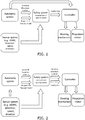
- FIG. 1 illustrates a simple embodiment of an autonomous self driven floor treatment vehicle, e.g. a floor cleaning vehicle of 70 kg or larger.
- An autonomy system outputs speed and direction control signals for navigating the vehicle according to a map or planned route, e.g. a map previously determined based on a scanning or other information of the room to be cleaned, or a route to be planned on the fly.
- the vehicle preferably has a battery for powering an electric propulsion motor or motors for driving one or more wheels directly or via a gear box.
- One or more wheels are involved in the functional steering of the vehicle.
- a sensor system is arranged to sense speed and direction of the vehicle, and to output speed and direction estimate signals accordingly. Further, the sensor system further comprising a scanning sensor arranged to scan a scan area around the vehicle for determining a position of an obstacle, e.g. a person, within the scan area and to generate a detection signal accordingly.
- the detection signal preferably comprises position data for detected obstacles, e.g. coordinate data.
- a safety system is arranged to receive the speed and direction estimate signals and to select a safety zone relative to the surface treatment vehicle accordingly in response to a safety zone selection algorithm.
- the safety system further receives the detection signal, e.g. including position data, and generates a safety stop signal in case the detection signal indicates an obstacle within the safety zone.
- a controller receives the speed and direction control signals, and control an electric propulsion motor or motors and a steering mechanism for driving the surface treatment vehicle at speed and direction in response to the speed and direction control signals.
- the controller is further arranged to control the propulsion motor or motors and/or a brake to bring the vehicle to a safety stop (e.g. an emergency stop) in case a safety stop signal is received.
- a safety stop e.g. an emergency stop
- the autonomy system can send a request signal to request a special mode of operation to the safety system different from the default mode of operation.
- the safety system then switches the safety zone selection algorithm from a normal safety zone selection algorithm to a special safety zone selection algorithm which selects the safety zone in a different way than the normal safety zone selection algorithm.
- this special mode can be a fast wall mode, where a higher speed than normal is allowed under the restriction of a more narrow range of directions. This allows high speed driving along a wall, and this mode can be requested where the autonomy system knows from the map, that driving along a (straight) wall is next on the planned route.
- the speed and direction control signals output by the autonomy system are applied to the safety system.
- the safety system compares the speed and direction control signals with the maximum speed and maximum direction given in the safety zone. In case the speed and control signals conflict with the maximum speed and maximum direction given in the safety zone, then the safety system generates a safety stop signal to the controller to stop the vehicle.
- This embodiment is a rather passive one, but still allows the special mode of operation. If preferred, the safety system can send an acknowledge signal to inform the autonomy system that the requested special mode has been entered.
- Either the autonomy system or the safety system can switch back to the normal safety zone selection algorithm.
- the safety zone selection algorithm can be a simple selection between a number of pre-calculated and pre-stored safety zones, one normal set corresponding to worst case direction and speed changes in the latency period, and one set for the special mode.
- the special mode set has a narrow symmetric or asymmetric direction limit e.g. allowing only a minimum direction changes required for driving the vehicle straight ahead, while a higher speed than the normal mode is allowed.
- FIG. 2 shows another embodiment, where the speed and direction control signals output by the autonomy system are applied to the safety system and routed via the safety system to the controller.
- the safety system compares the speed and direction control signals with a maximum speed and a maximum direction given in the safety zone. In case the speed and direction control signals conflict with the maximum speed and maximum direction given in the safety zone, then the safety system outputs limited speed and direction control signals to the controller which comply with the safety zone or to skip to output speed and direction control signals.
- the safety system simply outputs speed and direction control signals corresponding to speed and direction values in the received speed and direction control signals received by the autonomy system, in other words the safety system simply routes the speed and direction control signals though to the controller.
- FIG. 3 shows yet another embodiment, where the autonomy system sends planned trajectory data to the safety system and requests a special curved trajectory mode of operation.
- the safety system selects an asymmetric set of safety zones corresponding to the curve in the planned trajectory data.
- the direction is asymmetrically restricted compared to the normal mode of operation, thereby corresponding to the planned curved trajectory to be followed by the vehicle.
- FIG. 4 shows an example of safety zones in relation to a surface treatment vehicle, i.e. the restrictions on speed and direction.
- the dashed lines indicate direction restrictions and the solid arcs indicated zones corresponding to different speeds.
- the safety zones are calculated off-line taking into account the various delays involved in a safety stop procedure of the vehicle.
- FIG. 5 illustrates the vehicle driving along a wall (bold solid line), and the difference between a normal mode safety zone (grey area), and a fast wall mode safety zone where the direction change limits are more strict, while the allowed speed is higher.
- the fast wall mode safety zone is still symmetric.
- FIG. 6 illustrates another wall mode safety zone compared to (grey area), where the direction limit is asymmetric, since it is known that there is a wall to the right of the vehicle, thus changing direction to the right is limited, while changing direction to the left is less restricted.
- FIG. 7 shows an example of an asymmetric safety zone in an embodiment where the vehicle is planned to follow a curved trajectory (the curved dashed line), e.g. in the scenario where the vehicle is planned to turn left at the end of a room.
- the safety zone is asymmetric, thus allowing a higher speed in the curve compared to normal mode of operation, which would significantly reduce speed due to the presence of the two walls in the corner of the room.
- FIG. 8 illustrates step of a method embodiment of a surface treatment vehicle with an autonomy system for navigating the surface treatment vehicle, and a safety system arranged to provide a safety stop in response to a detection signal from a scanning sensor.
- the method comprising sending SRQ a request signal from an autonomy system to a safety system to request a special mode of operation, such as a fast wall mode.
- a special mode of operation such as a fast wall mode.
- the safety system comprises switching S_SSZA from a safety zone selection algorithm from a normal safety zone selection algorithm to a special safety zone selection algorithm which selects the safety zone in a different way than the normal safety zone selection algorithm, e.g. allowing a higher speed under the restriction of a more restricted direction.
- This method may be implemented as software, i.e. program code, in the safety system and autonomy system.
- the invention provides an autonomous surface treatment vehicle, e.g. a floor cleaner, with an autonomy system navigating according to a map, a scanning sensor to detect a position of an obstacle within and generate a detection signal.
- a safety system is arranged to generate a safety stop in case the detection signal indicates an obstacle within a safety zone.
- the safety system can enter a special mode of operation, e.g. upon request from the autonomy system, where a special safety zone selection algorithm selects the safety zone e.g. from a special set of pre-determined safety zones.
- a special safety zone selection algorithm selects the safety zone e.g. from a special set of pre-determined safety zones.
- such special mode can provide safety zones with a relaxed speed limit in combination with a restricted direction limit, so as to provide a faster driving near a wall or similar known obstacle.
Landscapes
- Engineering & Computer Science (AREA)
- Physics & Mathematics (AREA)
- Radar, Positioning & Navigation (AREA)
- Aviation & Aerospace Engineering (AREA)
- Remote Sensing (AREA)
- General Physics & Mathematics (AREA)
- Automation & Control Theory (AREA)
- Optics & Photonics (AREA)
- Electromagnetism (AREA)
- Control Of Position, Course, Altitude, Or Attitude Of Moving Bodies (AREA)
Priority Applications (5)
| Application Number | Priority Date | Filing Date | Title |
|---|---|---|---|
| EP18191058.9A EP3617828A1 (fr) | 2018-08-28 | 2018-08-28 | Véhicule de traitement de surface autonome à mode de paroi rapide |
| CA3103541A CA3103541A1 (fr) | 2018-08-28 | 2019-08-27 | Vehicule de traitement de surface autonome ayant un mode de paroi rapide |
| US17/270,707 US11953907B2 (en) | 2018-08-28 | 2019-08-27 | Autonomous surface treatment vehicle with fast wall mode |
| PCT/EP2019/072742 WO2020043676A1 (fr) | 2018-08-28 | 2019-08-27 | Véhicule de traitement de surface autonome ayant un mode de paroi rapide |
| EP19756380.2A EP3844586B1 (fr) | 2018-08-28 | 2019-08-27 | Véhicule de traitement de surface autonome à mode de paroi rapide |
Applications Claiming Priority (1)
| Application Number | Priority Date | Filing Date | Title |
|---|---|---|---|
| EP18191058.9A EP3617828A1 (fr) | 2018-08-28 | 2018-08-28 | Véhicule de traitement de surface autonome à mode de paroi rapide |
Publications (1)
| Publication Number | Publication Date |
|---|---|
| EP3617828A1 true EP3617828A1 (fr) | 2020-03-04 |
Family
ID=63683621
Family Applications (2)
| Application Number | Title | Priority Date | Filing Date |
|---|---|---|---|
| EP18191058.9A Withdrawn EP3617828A1 (fr) | 2018-08-28 | 2018-08-28 | Véhicule de traitement de surface autonome à mode de paroi rapide |
| EP19756380.2A Active EP3844586B1 (fr) | 2018-08-28 | 2019-08-27 | Véhicule de traitement de surface autonome à mode de paroi rapide |
Family Applications After (1)
| Application Number | Title | Priority Date | Filing Date |
|---|---|---|---|
| EP19756380.2A Active EP3844586B1 (fr) | 2018-08-28 | 2019-08-27 | Véhicule de traitement de surface autonome à mode de paroi rapide |
Country Status (4)
| Country | Link |
|---|---|
| US (1) | US11953907B2 (fr) |
| EP (2) | EP3617828A1 (fr) |
| CA (1) | CA3103541A1 (fr) |
| WO (1) | WO2020043676A1 (fr) |
Cited By (4)
| Publication number | Priority date | Publication date | Assignee | Title |
|---|---|---|---|---|
| EP3968115A1 (fr) * | 2020-09-11 | 2022-03-16 | Kabushiki Kaisha Toshiba | Corps mobile, dispositif de commande, dispositif de surveillance, procédé de commande et support d'enregistrement |
| WO2023193907A1 (fr) * | 2022-04-07 | 2023-10-12 | Volvo Autonomous Solutions AB | Procédé de gestion d'exigences opérationnelles lors de la conduite entre deux zones |
| EP4118509A4 (fr) * | 2020-03-10 | 2024-02-28 | Husqvarna AB | Système et procédé pour la navigation améliorée d'un outil de travail robotisé |
| US20240176351A1 (en) * | 2022-11-30 | 2024-05-30 | Omron Corporation | Mobile robot clearance systems |
Families Citing this family (1)
| Publication number | Priority date | Publication date | Assignee | Title |
|---|---|---|---|---|
| KR102707921B1 (ko) * | 2019-01-22 | 2024-09-23 | 삼성전자주식회사 | 로봇 및 그 제어 방법 |
Citations (4)
| Publication number | Priority date | Publication date | Assignee | Title |
|---|---|---|---|---|
| US20090043440A1 (en) * | 2007-04-12 | 2009-02-12 | Yoshihiko Matsukawa | Autonomous mobile device, and control device and program product for the autonomous mobile device |
| US20090322549A1 (en) * | 2008-05-09 | 2009-12-31 | Omron Scientific Technologies, Inc. | Method and Apparatus for Zone Selection in Area Monitoring Devices |
| WO2011141629A1 (fr) * | 2010-05-10 | 2011-11-17 | Sandvik Mining And Construction Oy | Procédé et appareil pour dispositifs de sécurité de véhicule minier |
| EP3223098A1 (fr) * | 2016-03-25 | 2017-09-27 | Panasonic Intellectual Property Corporation of America | Contrôleur, procédé de commande d'entraînement et support d'enregistrement lisible par ordinateur non transitoire mémorisant un programme |
Family Cites Families (12)
| Publication number | Priority date | Publication date | Assignee | Title |
|---|---|---|---|---|
| DE10240227B4 (de) | 2002-08-28 | 2006-04-06 | Daimlerchrysler Ag | Verfahren und Vorrichtung zum Betrieb einer Anzeigeeinrichtung an einer Arbeitsmaschine |
| AU2006306523B2 (en) | 2005-10-21 | 2011-05-19 | Deere & Company | Systems and methods for switching between autonomous and manual operation of a vehicle |
| EP2083209B1 (fr) | 2008-01-28 | 2012-10-17 | Sick Ag | Système de sécurité destiné à la mesure sans contact de voies et/ou de vitesses |
| EP2101193B1 (fr) | 2008-03-10 | 2012-05-30 | Sick Ag | Système de sécurité destiné à la mesure sans contact de positions, de voies et de vitesses |
| KR101212873B1 (ko) | 2010-05-20 | 2012-12-14 | 주식회사 에스원 | 청소 로봇 및 그 제어 방법 |
| EP2428862B1 (fr) | 2010-09-13 | 2013-01-09 | Sick Ag | Dispositif et procédé destinés à la commande de sécurité d'un véhicule |
| US8958911B2 (en) | 2012-02-29 | 2015-02-17 | Irobot Corporation | Mobile robot |
| EP2741483B1 (fr) | 2012-12-05 | 2022-01-26 | Vorwerk & Co. Interholding GmbH | Appareil de nettoyage automobile et procédé de fonctionnement d'un tel |
| DE102014106975A1 (de) | 2014-05-16 | 2015-11-19 | Vorwerk & Co. Interholding Gmbh | Selbsttätig verfahrbares Reinigungsgerät |
| JP6393523B2 (ja) | 2014-06-04 | 2018-09-19 | 北陽電機株式会社 | レーザセンサ及び自動搬送装置 |
| WO2017031365A1 (fr) * | 2015-08-18 | 2017-02-23 | Nilfisk, Inc. | Robot nettoyeur mobile |
| DE102016125408A1 (de) * | 2016-12-22 | 2018-06-28 | RobArt GmbH | Autonomer mobiler roboter und verfahren zum steuern eines autonomen mobilen roboters |
-
2018
- 2018-08-28 EP EP18191058.9A patent/EP3617828A1/fr not_active Withdrawn
-
2019
- 2019-08-27 US US17/270,707 patent/US11953907B2/en active Active
- 2019-08-27 CA CA3103541A patent/CA3103541A1/fr active Pending
- 2019-08-27 WO PCT/EP2019/072742 patent/WO2020043676A1/fr not_active Ceased
- 2019-08-27 EP EP19756380.2A patent/EP3844586B1/fr active Active
Patent Citations (4)
| Publication number | Priority date | Publication date | Assignee | Title |
|---|---|---|---|---|
| US20090043440A1 (en) * | 2007-04-12 | 2009-02-12 | Yoshihiko Matsukawa | Autonomous mobile device, and control device and program product for the autonomous mobile device |
| US20090322549A1 (en) * | 2008-05-09 | 2009-12-31 | Omron Scientific Technologies, Inc. | Method and Apparatus for Zone Selection in Area Monitoring Devices |
| WO2011141629A1 (fr) * | 2010-05-10 | 2011-11-17 | Sandvik Mining And Construction Oy | Procédé et appareil pour dispositifs de sécurité de véhicule minier |
| EP3223098A1 (fr) * | 2016-03-25 | 2017-09-27 | Panasonic Intellectual Property Corporation of America | Contrôleur, procédé de commande d'entraînement et support d'enregistrement lisible par ordinateur non transitoire mémorisant un programme |
Cited By (8)
| Publication number | Priority date | Publication date | Assignee | Title |
|---|---|---|---|---|
| EP4118509A4 (fr) * | 2020-03-10 | 2024-02-28 | Husqvarna AB | Système et procédé pour la navigation améliorée d'un outil de travail robotisé |
| EP3968115A1 (fr) * | 2020-09-11 | 2022-03-16 | Kabushiki Kaisha Toshiba | Corps mobile, dispositif de commande, dispositif de surveillance, procédé de commande et support d'enregistrement |
| JP2022047381A (ja) * | 2020-09-11 | 2022-03-24 | 株式会社東芝 | 移動体、制御装置、監視装置、制御方法、及びプログラム |
| CN114248857A (zh) * | 2020-09-11 | 2022-03-29 | 株式会社东芝 | 移动体、控制装置、监视装置、控制方法以及程序 |
| WO2023193907A1 (fr) * | 2022-04-07 | 2023-10-12 | Volvo Autonomous Solutions AB | Procédé de gestion d'exigences opérationnelles lors de la conduite entre deux zones |
| WO2023194391A1 (fr) * | 2022-04-07 | 2023-10-12 | Volvo Autonomous Solutions AB | Procédé de gestion d'exigences opérationnelles lors de la conduite entre deux zones |
| US20240176351A1 (en) * | 2022-11-30 | 2024-05-30 | Omron Corporation | Mobile robot clearance systems |
| US12253856B2 (en) * | 2022-11-30 | 2025-03-18 | Omron Corporation | Mobile robot clearance systems |
Also Published As
| Publication number | Publication date |
|---|---|
| US20220197293A1 (en) | 2022-06-23 |
| US11953907B2 (en) | 2024-04-09 |
| EP3844586C0 (fr) | 2023-11-22 |
| EP3844586A1 (fr) | 2021-07-07 |
| WO2020043676A1 (fr) | 2020-03-05 |
| EP3844586B1 (fr) | 2023-11-22 |
| CA3103541A1 (fr) | 2020-03-05 |
Similar Documents
| Publication | Publication Date | Title |
|---|---|---|
| US11953907B2 (en) | Autonomous surface treatment vehicle with fast wall mode | |
| US20200397202A1 (en) | Floor treatment by means of an autonomous mobile robot | |
| US20210223779A1 (en) | Systems and methods for rerouting robots to avoid no-go zones | |
| US10350762B2 (en) | Autonomously moving body, movement controlling method, and recording medium storing movement controlling program | |
| US11402850B2 (en) | Robotic cleaning device with operating speed variation based on environment | |
| EP2879010B1 (fr) | Robot nettoyant et son procédé de commande | |
| US10254756B2 (en) | Cleaning robot and method for controlling the same | |
| CN105899112B (zh) | 自主移动机器人 | |
| EP3705968B1 (fr) | Procédé de commande et de prédiction de trajet de robot | |
| Parikh et al. | Incorporating user inputs in motion planning for a smart wheelchair | |
| KR102301758B1 (ko) | 자율 주행 가능한 이동 로봇 및 이의 주행 제어 방법 | |
| US11013390B2 (en) | Autonomous traveler | |
| CN105182980A (zh) | 一种自动清洁设备的控制系统及控制方法 | |
| KR20160120841A (ko) | 청소 로봇을 이용한 스마트 청소 시스템 | |
| CN112806912A (zh) | 机器人的清洁控制方法、装置及机器人 | |
| JP2021105963A (ja) | 自律走行作業装置 | |
| JP2018015396A (ja) | 自律走行型掃除機 | |
| JP7345132B2 (ja) | 自律走行型掃除機、自律走行型掃除機の制御方法、及び、プログラム | |
| JP6761309B2 (ja) | 自律移動装置、自律移動方法及び自律移動システム | |
| JP2021101298A (ja) | 自律走行作業装置 | |
| JP2020009338A (ja) | 自律走行型掃除機 | |
| KR100757062B1 (ko) | 이동로봇의 장애물 감지 장치 |
Legal Events
| Date | Code | Title | Description |
|---|---|---|---|
| PUAI | Public reference made under article 153(3) epc to a published international application that has entered the european phase |
Free format text: ORIGINAL CODE: 0009012 |
|
| AK | Designated contracting states |
Kind code of ref document: A1 Designated state(s): AL AT BE BG CH CY CZ DE DK EE ES FI FR GB GR HR HU IE IS IT LI LT LU LV MC MK MT NL NO PL PT RO RS SE SI SK SM TR |
|
| AX | Request for extension of the european patent |
Extension state: BA ME |
|
| STAA | Information on the status of an ep patent application or granted ep patent |
Free format text: STATUS: THE APPLICATION IS DEEMED TO BE WITHDRAWN |
|
| 18D | Application deemed to be withdrawn |
Effective date: 20200905 |