EP3968115A1 - Corps mobile, dispositif de commande, dispositif de surveillance, procédé de commande et support d'enregistrement - Google Patents
Corps mobile, dispositif de commande, dispositif de surveillance, procédé de commande et support d'enregistrement Download PDFInfo
- Publication number
- EP3968115A1 EP3968115A1 EP21175693.7A EP21175693A EP3968115A1 EP 3968115 A1 EP3968115 A1 EP 3968115A1 EP 21175693 A EP21175693 A EP 21175693A EP 3968115 A1 EP3968115 A1 EP 3968115A1
- Authority
- EP
- European Patent Office
- Prior art keywords
- velocity
- movable body
- threshold value
- movement
- omnidirectional movable
- Prior art date
- Legal status (The legal status is an assumption and is not a legal conclusion. Google has not performed a legal analysis and makes no representation as to the accuracy of the status listed.)
- Granted
Links
Images








Classifications
-
- G—PHYSICS
- G05—CONTROLLING; REGULATING
- G05D—SYSTEMS FOR CONTROLLING OR REGULATING NON-ELECTRIC VARIABLES
- G05D1/00—Control of position, course, altitude or attitude of land, water, air or space vehicles, e.g. using automatic pilots
- G05D1/02—Control of position or course in two dimensions
- G05D1/021—Control of position or course in two dimensions specially adapted to land vehicles
- G05D1/0268—Control of position or course in two dimensions specially adapted to land vehicles using internal positioning means
- G05D1/0272—Control of position or course in two dimensions specially adapted to land vehicles using internal positioning means comprising means for registering the travel distance, e.g. revolutions of wheels
-
- B—PERFORMING OPERATIONS; TRANSPORTING
- B60—VEHICLES IN GENERAL
- B60W—CONJOINT CONTROL OF VEHICLE SUB-UNITS OF DIFFERENT TYPE OR DIFFERENT FUNCTION; CONTROL SYSTEMS SPECIALLY ADAPTED FOR HYBRID VEHICLES; ROAD VEHICLE DRIVE CONTROL SYSTEMS FOR PURPOSES NOT RELATED TO THE CONTROL OF A PARTICULAR SUB-UNIT
- B60W30/00—Purposes of road vehicle drive control systems not related to the control of a particular sub-unit, e.g. of systems using conjoint control of vehicle sub-units
- B60W30/14—Adaptive cruise control
- B60W30/143—Speed control
- B60W30/146—Speed limiting
-
- B—PERFORMING OPERATIONS; TRANSPORTING
- B62—LAND VEHICLES FOR TRAVELLING OTHERWISE THAN ON RAILS
- B62D—MOTOR VEHICLES; TRAILERS
- B62D63/00—Motor vehicles or trailers not otherwise provided for
- B62D63/02—Motor vehicles
-
- B—PERFORMING OPERATIONS; TRANSPORTING
- B60—VEHICLES IN GENERAL
- B60B—VEHICLE WHEELS; CASTORS; AXLES FOR WHEELS OR CASTORS; INCREASING WHEEL ADHESION
- B60B19/00—Wheels not otherwise provided for or having characteristics specified in one of the subgroups of this group
- B60B19/003—Multidirectional wheels
-
- B—PERFORMING OPERATIONS; TRANSPORTING
- B60—VEHICLES IN GENERAL
- B60K—ARRANGEMENT OR MOUNTING OF PROPULSION UNITS OR OF TRANSMISSIONS IN VEHICLES; ARRANGEMENT OR MOUNTING OF PLURAL DIVERSE PRIME-MOVERS IN VEHICLES; AUXILIARY DRIVES FOR VEHICLES; INSTRUMENTATION OR DASHBOARDS FOR VEHICLES; ARRANGEMENTS IN CONNECTION WITH COOLING, AIR INTAKE, GAS EXHAUST OR FUEL SUPPLY OF PROPULSION UNITS IN VEHICLES
- B60K7/00—Disposition of motor in, or adjacent to, traction wheel
- B60K7/0007—Disposition of motor in, or adjacent to, traction wheel the motor being electric
-
- G—PHYSICS
- G05—CONTROLLING; REGULATING
- G05D—SYSTEMS FOR CONTROLLING OR REGULATING NON-ELECTRIC VARIABLES
- G05D1/00—Control of position, course, altitude or attitude of land, water, air or space vehicles, e.g. using automatic pilots
- G05D1/02—Control of position or course in two dimensions
- G05D1/021—Control of position or course in two dimensions specially adapted to land vehicles
- G05D1/0212—Control of position or course in two dimensions specially adapted to land vehicles with means for defining a desired trajectory
- G05D1/0214—Control of position or course in two dimensions specially adapted to land vehicles with means for defining a desired trajectory in accordance with safety or protection criteria, e.g. avoiding hazardous areas
-
- G—PHYSICS
- G05—CONTROLLING; REGULATING
- G05D—SYSTEMS FOR CONTROLLING OR REGULATING NON-ELECTRIC VARIABLES
- G05D1/00—Control of position, course, altitude or attitude of land, water, air or space vehicles, e.g. using automatic pilots
- G05D1/02—Control of position or course in two dimensions
- G05D1/021—Control of position or course in two dimensions specially adapted to land vehicles
- G05D1/0212—Control of position or course in two dimensions specially adapted to land vehicles with means for defining a desired trajectory
- G05D1/0223—Control of position or course in two dimensions specially adapted to land vehicles with means for defining a desired trajectory involving speed control of the vehicle
-
- G—PHYSICS
- G05—CONTROLLING; REGULATING
- G05D—SYSTEMS FOR CONTROLLING OR REGULATING NON-ELECTRIC VARIABLES
- G05D1/00—Control of position, course, altitude or attitude of land, water, air or space vehicles, e.g. using automatic pilots
- G05D1/02—Control of position or course in two dimensions
- G05D1/021—Control of position or course in two dimensions specially adapted to land vehicles
- G05D1/0231—Control of position or course in two dimensions specially adapted to land vehicles using optical position detecting means
- G05D1/0238—Control of position or course in two dimensions specially adapted to land vehicles using optical position detecting means using obstacle or wall sensors
-
- G—PHYSICS
- G05—CONTROLLING; REGULATING
- G05D—SYSTEMS FOR CONTROLLING OR REGULATING NON-ELECTRIC VARIABLES
- G05D1/00—Control of position, course, altitude or attitude of land, water, air or space vehicles, e.g. using automatic pilots
- G05D1/02—Control of position or course in two dimensions
- G05D1/021—Control of position or course in two dimensions specially adapted to land vehicles
- G05D1/0231—Control of position or course in two dimensions specially adapted to land vehicles using optical position detecting means
- G05D1/0238—Control of position or course in two dimensions specially adapted to land vehicles using optical position detecting means using obstacle or wall sensors
- G05D1/024—Control of position or course in two dimensions specially adapted to land vehicles using optical position detecting means using obstacle or wall sensors in combination with a laser
Definitions
- Embodiments of the present invention relate to a movable body, a control device, a monitoring device, a control method, and a storage medium that stores a program.
- moving bodies such as autonomously moving (traveling) robots or transport vehicles have been put into practical use in order to save labor in transporting cargo in a distribution warehouse.
- Examples of a scheme for controlling traveling of a movable body include a guide scheme for causing the movable body to travel along a guide line on a floor surface, and a guideless scheme for detecting an environment around a movable body and performing autonomous control.
- the movable body includes a non-contact obstacle detector that detects an obstacle within a monitoring area, and a control unit that stops the movable body using a detection result of the obstacle detector. This makes it possible to stop the movable body so that the movable body does not collide with an obstacle even when there is the obstacle in a traveling direction of the movable body.
- a movable body including three or more drive wheels and an omnidirectional moving mechanism capable of moving in all directions has become known.
- the drive wheels used in the omnidirectional movement mechanism for example, mecanum wheels are used.
- the movable body that can move in all directions can instantly perform a complex operation such as moving forward, changing a direction, moving sideways, and turning on the spot.
- mobile bodies including a safety control system for the purpose of protecting humans.
- the safety control system decelerates or stops the movable body, for example, when an obstacle within a monitoring area is detected by a sensor or the like.
- a movable body when a movable body is constantly detecting an object within a monitoring area as an obstacle, for example, the movable body stops when approaching a transport target object, and may not be able to achieve an original purpose of transporting a transport target object. Therefore, when the movable body travels at a predetermined velocity or lower, the movable body is regarded as having moved near the transport target object, and the monitoring area can be reduced so that the transport target object is not detected as an obstacle.
- FIGS. 1A and 1C are diagrams illustrating an example of an overall configuration of an omnidirectional movable body 1 according to a first embodiment.
- the omnidirectional movable body 1 is a transport robot that includes an omnidirectional moving mechanism and autonomously moves (travels). Specifically, the omnidirectional movable body 1 transports a basket cart for distribution within a distribution warehouse.
- the omnidirectional movable body 1 includes a drive system and a control system.
- the drive system includes four mecanum wheels 11a to 11d, four drive motors 12a to 12d, and four rotational velocity detectors 13a to 13d.
- the mecanum wheels 11a to 11d are simply referred to as "mecanum wheels 11" when it is not necessary to distinguish the mecanum wheels 11a to 11d.
- the drive motors 12a to 12d and the rotational velocity detectors 13a to 13d are also simply referred to as a "drive motor 12" and a “rotational velocity detector 13", respectively.
- the mecanum wheels 11 allow the omnidirectional movable body 1 to instantly perform forward movement, change of direction, movement to a sideway, turning on the spot, and the like without a preparation operation by barrels provided on a wheel circumference rotating. Details of the mecanum wheel 11 will be described below with reference to FIG. 2 .
- the drive motor 12 generates a torque to drive the mecanum wheel 11.
- the drive motor 12 includes a function of a decelerator.
- the decelerator decelerates the rotation of the drive motor 12 (increases the torque) and transmits a rotational force to the mecanum wheel 11.
- the rotational velocity detector 13 is a velocity sensor, and detects a rotational velocity of the mecanum wheel 11 and converts a rotation amount into an electrical signal.
- a rotational velocity detector 13 for example, a rotary encoder is used.
- a brake 14 for stopping the rotation of each wheel may be included. It is preferable to use the brake 14 of a type in which a braking force acts when electrical current supply to the drive motor 12 is stopped.
- An arrow line connecting the motor control circuit 23 and the drive motor 12 in FIG. 1A indicates a wiring for motor driving and a wiring for energizing the brake 14 when the brake 14 is used.
- the control system includes an external communication device 21, a main controller 22, a motor control circuit 23, a safety laser scanner 31, a velocity monitoring module 32, and a circuit breaker 33.
- the external communication device 21 performs wireless communication with an external communication device via a network.
- the external communication device 21 receives a movement plan of the omnidirectional movable body 1 at a predetermined timing from an external computer device that manages all the omnidirectional mobile bodies 1 in the distribution warehouse.
- the movement plan includes various types of information regarding the transport of the omnidirectional movable body 1.
- the movement plan includes, for example, information on a movement route of the omnidirectional movable body 1 in a distribution warehouse, information on an area in which the omnidirectional movable body 1 travels at a low velocity, information indicating a basket cart which is a transport target object, and information indicating a transport destination of the transport target object.
- the external communication device 21 outputs information received from the external computer device to the main controller 22.
- the external communication device 21 is a communication interface.
- the network includes, for example, the Internet, a wide area network (WAN), a local area network (LAN), a cellular network, Wi-Fi (registered trademark), Bluetooth (registered trademark), near field communication (NFC), and infrared communication.
- the safety laser scanner 31 is a sensor that detects the presence of an object around the omnidirectional movable body 1. Specifically, the safety laser scanner performs scanning with an infrared laser and measures time delay of reflected light to measure a distance to a surrounding object or a shape of the object. The safety laser scanner 31 is attached to the front side of the omnidirectional movable body 1, for example.
- the safety laser scanner 31 determines whether or not there is an object in a preset area (monitoring area). When the safety laser scanner 31 determines that there is an object in the preset area, the safety laser scanner 31 outputs a stop signal for stopping a device such as the drive motor 12 to the main controller 22.
- an output signal of the safety laser scanner includes a non-safety signal and a safety signal.
- the non-safety signal is used for the purpose of protecting the omnidirectional movable body 1 through deceleration of the omnidirectional movable body 1 or the like.
- the safety signal is used as a signal for reliably stopping the omnidirectional movable body 1 when a dangerous event occurs, using a relay for shutting off power or the like.
- the non-safety signal is output to, for example, the main controller 22.
- the safety signal is output to, for example, the circuit breaker 33 or the main controller 22.
- the main controller 22 outputs an operation signal for switching an operation of the omnidirectional movable body 1 to the motor control circuit 23 using the movement plan of the omnidirectional movable body 1.
- the main controller 22 is not limited to acquiring the movement plan wirelessly from the external communication device 21, and may acquire the movement plan through an operation input of an operator or may acquire the movement plan through cable connection to an external device.
- the main controller 22 outputs an operation signal for decelerating the omnidirectional movable body 1 to the motor control circuit 23.
- the motor control circuit 23 controls the rotation of the drive motor using the operation signal output from the main controller 22 to move or decelerate the omnidirectional movable body 1 at a predetermined velocity in a predetermined direction. Stopping of rotation due to inertia due to loss of a driving force of each drive motor 12, or braking torque dissipation of regenerative power in electrical resistors of the motor control circuit 23 and a drive motor system when power of the motor control circuit 23 is shut off, in addition to the control stop according to a number-of-rotations command value from the main controller 22, can be used as a means for stopping the omnidirectional movable body 1. Further, when the brake 14 is included, a braking force is generated by cutting off the energization from the motor control circuit 23 to the brake 14. This makes it possible to also stop the omnidirectional movable body 1.
- a control system for an autonomous mobile robot including the omnidirectional movable body 1 includes two control systems includes a normal control system Nr and a safety control system Sf, as illustrated in FIG. 1C .
- the normal control system Nr is a control system for detecting a situation of surrounding obstacles or the like and efficiently moving the omnidirectional movable body 1.
- the normal control system Nr controls the operation of the omnidirectional movable body 1 from distance data obtained by the laser scanner 31b, map information, and the movement plan.
- the distance data of the laser scanner 31b is used for the normal control system Nr, but distance data (non-safety signal) from the safety laser scanner can also be used.
- the normal control system Nr performs creation of the map information using, for example, distance data from surrounding objects included in a non-safety signal from the laser scanner 31b or the safety laser scanner 31. Further, the normal control system Nr has a movement plan or a function of an interface that is operated by an operator.
- the control system of the omnidirectional movable body 1 includes the safety control system Sf, in addition to the normal control system Nr.
- the safety control system Sf is a control system mainly for ensuring safety.
- the normal control system Nr main controller 22
- the safety control system Sf receives the operation signal to invalidate a protection area or change a threshold value of protective stop velocity.
- the muting signal is directly output to the safety laser scanner using the operation signal from the main controller 22 without the safety control system Sf (the velocity monitoring module 32) intervening.
- the main controller 22 outputs the operation signal (muting signal) at the time of hanging-up
- the muting signal may continue to be output and the omnidirectional movable body 1 may continue to travel in a state in which a safety function of the safety laser scanner is partially stopped.
- the threshold value of protective stop velocity or the like is accidentally changed due to an error or the like or an protective stop is made with the accidentally changed threshold value of protective stop velocity.
- the safety control system Sf (the velocity monitoring module 32) has a low risk of malfunction and is less likely to fail. Even when a failure occurs, the velocity monitoring module 32 can cut off the power supplied to the motor control circuit 23 so that a safe state can be maintained. Thus, it is possible to ensure the reliability of the safety control system Sf by changing the range of the protection area 401 and the threshold value of protective stop velocity through the interposed velocity monitoring module 32.
- the safety control system Sf monitors a surrounding situation using the safety laser scanner 31 and reliably stops the omnidirectional movable body 1 when approach of an object such as an obstacle is detected.
- reference sign 40 indicates a control signal including the safety signal.
- the safety laser scanner 31 detects an object within the protection area
- the safety laser scanner 31 outputs the safety signal to the circuit breaker 33.
- the velocity monitoring module 32 outputs the safety signal to the circuit breaker 33 when a movement velocity of the omnidirectional movable body 1 reaches the threshold value of protective stop velocity (for example, 1.1 m/s).
- the circuit breaker 33 shuts off power supplied to the motor control circuit 23 to stop the driving of each mecanum wheel 11.
- the rotation is stopped due to inertia due to loss of a driving force, or the stop can also be realized by generation of a braking torque due to the electrical resistors (dissipation of regenerative power) of the motor control circuit 23 and a drive motor system or use of a braking force of the brake 14 when the brake 14 is included.
- the circuit breaker 33 is realized by, for example, a mirror contactor. Further, although not illustrated in FIG. 1C , when the motor control circuit includes an protective stop function through an external signal input, the stop can also be realized by inputting the safety signal input to the circuit breaker 33 to the motor control circuit.
- the safety control system Sf is required to have robustness that does not fail for a long period of time to reliably stop the omnidirectional movable body 1 even when an abnormality occurs in the normal control system Nr, a function of detecting a failure, a function of safely stopping the omnidirectional movable body 1 at the time of failure, and the like.
- a protection area and a warning area are set toward a distance from a center of the safety laser scanner 31 in the monitoring area.
- the safety laser scanner 31 can store a plurality of patterns indicating the range of the monitoring area.
- the velocity monitoring module 32 switches patterns set in the safety laser scanner 31. Specifically, the velocity monitoring module 32 switches a pattern (a pattern indicating the range of the warning area or protection area) according to each of operations, such as an operation in which the omnidirectional movable body 1 travels alone, an operation in which the transport target object is transported, or an operation in which the transport target object is picked up.
- a pattern a pattern indicating the range of the warning area or protection area
- the convenience of the omnidirectional movable body 1 may be hindered and an original purpose of use may not be achieved.
- the transport target object may be detected as an obstacle and the omnidirectional movable body 1 may stop when the safety control system Sf functions. That is, it is not possible to pick up the transport target object (crawl under the transport target object) and to achieve the original purpose of transporting the transport target object in some cases.
- the safety control system Sf temporarily reduces the range of the protection area set in the safety laser scanner 31 or invalidates (mutes) the range of the protection area, it is possible to prevent the impairment of convenience.
- the velocity monitoring module 32 temporarily reduces or invalidates the protection area. Accordingly, the omnidirectional movable body 1 can pick up the transport target object.
- the safety control system Sf changes the threshold value of protective stop velocity for making an protective stop of the omnidirectional movable body 1. Specifically, the safety control system Sf changes the range of the protection area to a second threshold value of protective stop velocity (for example, 0.3m/s)) lower than a first threshold value of protective stop velocity (for example, 1.1 m/s) before the change.
- a second threshold value of protective stop velocity for example, 0.3m/s
- a first threshold value of protective stop velocity for example, 1.1 m/s
- a signal that is transmitted between the respective devices may include a signal for periodically detecting a failure.
- the device that receives the signal may include a time filter or the like that does not react to the signal for detecting a failure.
- a signal line between the respective devices indicates one line, but may be duplicated like a signal wiring used in a general safety control system.
- industrial communication protocols for example, Ethernet/IP, PROFINET, EtherCAT, Profibus, Modbus, CC-Link, and CANopen
- safety-compatible communication protocols may be used for information transmission between the respective devices.
- the main controller 22 is realized by a hardware processor such as a central processing unit (CPU) executing a program (software). Further, each of the motor control circuit 23 and the velocity monitoring module 32 are each realized by hardware (including a circuit unit; circuitry).
- a hardware processor such as a central processing unit (CPU) executing a program (software).
- each of the motor control circuit 23 and the velocity monitoring module 32 are each realized by hardware (including a circuit unit; circuitry).
- each of the motor control circuit 23 and the velocity monitoring module 32 may be realized by a hardware processor such as a CPU executing a program. Further, in the main controller 22, the motor control circuit 23, and the velocity monitoring module 32, some or all of components thereof may be realized by hardware (including a circuit unit; circuitry) such as a large scale integration (LSI), an application specific integrated circuit (ASIC), a field-programmable gate array (FPGA), or a graphics processing unit (GPU) or may be realized by software and hardware in cooperation.
- LSI large scale integration
- ASIC application specific integrated circuit
- FPGA field-programmable gate array
- GPU graphics processing unit
- the program may be stored in a storage device (a storage device including a non-transitory storage medium) such as a hard disk drive (HDD) or a flash memory in advance or may be stored in a removable storage medium (a non-transitory storage medium) such as a DVD or a CD-ROM and installed by the storage medium being mounted in a drive device.
- a storage device a storage device including a non-transitory storage medium
- HDD hard disk drive
- flash memory in advance
- a removable storage medium a non-transitory storage medium
- Each functional unit is realized by the processor executing the program stored in the storage unit.
- control signal 40 (Specific example of control signal 40)
- FIG. 1B is a diagram illustrating a specific example of a control signal 40.
- the control signal 40 illustrated in FIG. 1A includes a deceleration (alarm) signal 41, an operation mode signal 42, and an protective stop signal 43.
- the deceleration signal 41 is a signal ("WNG" in FIG. 1C ) that is output from the safety laser scanner 31 to the main controller 22 when the object in the warning area is detected by the safety laser scanner 31.
- the main controller 22 controls the motor control circuit 23 such that the velocity of the omnidirectional movable body 1 is reduced.
- the operation mode signal 42 is a signal (the operation signal Sg in FIG. 1C ) that is output from the main controller 22 to the velocity monitoring module 32, for example, when transition to a docking mode occurs.
- the velocity monitoring module 32 outputs a signal for temporarily reducing the range of the protection area set in the safety laser scanner 31 or invalidating (muting) the range of the protection area.
- the protective stop signal 43 is a signal (“OSSD" in FIG. 1C ) that is output from the velocity monitoring module 32 to the circuit breaker 33 when the velocity monitoring module 32 determines that a velocity value is abnormal, for example, the velocity of the omnidirectional movable body 1 has reached a threshold value of velocity in design.
- the circuit breaker 33 cuts off the power supplied to the motor control circuit 23. Accordingly, the velocity of the omnidirectional movable body 1 is decelerated (stopped).
- FIG. 2 is a diagram illustrating an example of a configuration of the mecanum wheels 11a to 11d.
- each of the mecanum wheels 11a to 11d includes a plurality of barrel-shaped rollers 201.
- the plurality of barrel-shaped rollers 201 are attached on an outer circumference of the wheel at an angle with respect to a wheel shaft.
- the wheel diameters of the mecanum wheels 11a to 11d are the same wheel diameters. However, these wheel diameters may be different wheel diameters.
- a center line 202 indicates an inclination of the barrel-shaped roller 201.
- the plurality of barrel-shaped rollers 201 rotate at the same rotational velocity in the same direction.
- There are two types in the mecanum wheels 11a to 11d including right-handed wheels with the barrel-shaped rollers 201 tilted upward to the right and left-handed wheels with the barrel-shaped rollers 201 tilted upward to the left.
- the mecanum wheels 11a to 11d are disposed at four locations at the front, rear, left, and right of a housing 300 (see FIG. 3 ) of the omnidirectional movable body 1, as in a four-wheeled automobile.
- mecanum wheels 11a and 11b different types (right hand and left hand) of mecanum wheels 11a and 11b (11c and 11d) disposed on the right side (or left side) are disposed at the front and rear. Further, for the mecanum wheels 11a and 11d (11b and 11c) disposed on a diagonal line of the omnidirectional movable body 1, the same type of right-handed (left-handed) mecanum wheels are disposed. Both of the mecanum wheels 11a and 11d and the mecanum wheels 11b and 11c may be for right hand or left hand.
- the right hand or left hand is a design matter and can be arbitrary.
- each wheel is rotated at a predetermined velocity so that the omnidirectional movable body 1 can be moved in one direction.
- the omnidirectional movable body 1 can move forward, backward, or to a sideway, turn, and move diagonally, for example.
- FIG. 3 is a diagram illustrating an example of a coordinate system of the omnidirectional movable body 1 and the mecanum wheels 11a to 11d.
- an x-axis, y-axis, and z-axis are defined by a right-handed coordinate system.
- the x-axis indicates a front-rear direction.
- the y-axis indicates a lateral direction.
- the z-axis indicates a height direction.
- a velocity in the forward direction of the omnidirectional movable body 1 is a main movement velocity Vx.
- Vy is a lateral velocity of the omnidirectional movable body 1.
- ⁇ is a turning velocity of the omnidirectional movable body 1.
- a rotational velocity of the wheel of the mecanum wheel 11a is ⁇ 1
- a rotational velocity of the wheel of the mecanum wheel 11b is ⁇ 2
- a rotational velocity of the wheel of the mecanum wheel 11c is ⁇ 3
- a rotational velocity of the wheel of the mecanum wheel 11d is ⁇ 4.
- the omnidirectional movable body 1 moves forward at the main movement velocity Vx of 1 m/s in an x-axis direction.
- the omnidirectional movable body 1 moves to a sideway at a velocity Vy of 1 m/s in the y-axis direction.
- the omnidirectional movable body 1 turns at an angular velocity of co ⁇ 1 rad/s on the spot.
- Signs in rotation and translation directions are determined by a defined coordinate system or orientation, and the disposition of left and right types of the mecanum wheels 11.
- a defined coordinate system or orientation and the disposition of left and right types of the mecanum wheels 11.
- signs of the moving direction differ from in the above example.
- Equation (1) the movement velocity of the omnidirectional movable body 1 can be calculated from the rotational velocity of each mecanum wheel 11.
- Equation (1) is an equation called forward kinematics.
- B is a 4 ⁇ 3 matrix.
- Rw indicates a wheel radius.
- Matrix components includes the coefficient related to wheel disposition of the mecanum wheel 11.
- the main controller 22 calculates the target rotational velocities of the four mecanum wheels 11 using the target velocity of the omnidirectional movable body 1 by using relationships of Equation (1) and Equation (2).
- the main controller 22 can move the omnidirectional movable body 1 at a desired velocity in a desired direction by outputting the calculated target rotational velocity to the motor control circuit 23.
- FIG. 4 is a diagram illustrating an example of the monitoring area 400.
- the monitoring area 400 in which an object is detected by the safety laser scanner 31 is set in front of the omnidirectional movable body 1.
- the monitoring area 400 includes a protection area 401 close to the omnidirectional movable body 1 and a warning area 402 distant from the protection area 401.
- the protection area 401 is set in consideration of a distance until the omnidirectional movable body 1 stops, and is, for example, an area within 50 cm in a forward direction from the omnidirectional movable body 1.
- the circuit breaker 33 cuts off the power supplied to the motor control circuit 23 so that the omnidirectional movable body 1 stops.
- the warning area 402 is, for example, an area within 50 cm to several m in the forward direction of the omnidirectional movable body 1.
- the main controller 22 controls the motor control circuit 23 to decelerate the omnidirectional movable body 1.
- the monitoring area 400 (the protection area 401 and the warning area 402) is an area of which a range can be changed according to situations.
- FIG. 5A is a diagram illustrating an example of the changed monitoring area 400.
- a transport target object 500 (basket cart) is present in front of the omnidirectional movable body 1. That is, a situation in which the omnidirectional movable body 1 approaches the transport target object 500 in order to transport the transport target object 500 on the basis of the movement plan is illustrated.
- the safety laser scanner 31 detects the transport target object 500 as an obstacle
- the omnidirectional movable body 1 stops so that the omnidirectional movable body 1 cannot transport the transport target object 500.
- the range of the protection area 401 is temporarily reduced (or invalidated) so that the transport target object 500 is not detected as an obstacle. Further, the warning area 402 is temporarily invalidated, for example. This makes it possible for the omnidirectional movable body 1 to pick up the transport target object 500 (crawl under the transport target object 500).
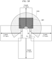
- FIG. 5B is a diagram illustrating an example of the threshold value of protective stop velocity.
- the detection area 510 there is a detection area 510 that can be detected by the safety laser scanner 31 in front of the omnidirectional movable body 1.
- the detection area 510 has a radius of about 10 m around the omnidirectional movable body 1 and is formed at 270 ° in front of the omnidirectional movable body 1.
- the protection area 401 is included in the detection area 510.
- the threshold value of protective stop velocity is set to, for example, 1.1 m/s in all directions. That is, it is shown that in normal traveling, when the movement velocity of the omnidirectional movable body 1 reaches 1.1 m/s, an protective stop is made.
- FIG. 5B there is a detection area 510 that can be detected by the safety laser scanner 31 in front of the omnidirectional movable body 1.
- the detection area 510 has a radius of about 10 m around the omnidirectional movable body 1 and is formed at 270
- Vx direction the threshold values of the velocities in a front-rear direction (Vx direction) and a left-right direction (Vy direction) are shown, but the same applies to a velocity in a diagonal direction and a turning velocity (a velocity including Vx, Vy, and ⁇ components).
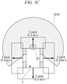
- FIG. 5C is a diagram illustrating an example of a threshold value of protective stop velocity at the time of muting.
- the protection area 401 disappears in front of the omnidirectional movable body 1, that is, the protection area 401 is invalidated.
- the threshold value of protective stop velocity is set to, for example, 0.3 m/s in all directions. That is, it is shown that when the movement velocity of the omnidirectional movable body 1 reaches 0.3 m/s in traveling at the time of muting, an protective stop is made.
- FIG. 5C is a diagram illustrating an example of a threshold value of protective stop velocity at the time of muting.
- the rotational velocity of the mecanum wheel 11 and the velocity of the omnidirectional movable body 1 can be related by and calculated using Equations (1), (2), and (3).
- a velocity used for a velocity determination it is also possible to determine the velocity using a condition determination using the number of rotations of each wheel and a logical operation result in order to simplify a calculation process. Next, this way of thinking will be described.
- FIG. 6 is a diagram illustrating an example of a relationship between the velocity of the omnidirectional movable body 1 and the rotational velocity (angular velocity) of the mecanum wheel 11.
- a horizontal axis indicates an absolute value
- can be expressed using Equation (3). [Math. 3] V Vx 2 + Vy 2
- a vertical axis indicates an absolute value
- indicates any one of 0 rad/s, 0.25 rad/s, and 0.5 rad/s.
- of the maximum value among the rotational velocities of the four mecanum wheels 11 is 0.3 rad/s or lower, so that the velocity
- a threshold value for example, 0.3 rad/s
- FIG. 7 is a diagram illustrating a velocity determination logic according to the first embodiment.
- a logic 700 illustrated in FIG. 7 is a logic that determines whether or not the rotational velocity of each of the mecanum wheel 11 is equal to or lower than a threshold value and outputs a logical product of determination results.
- the logic 700 indicates a logic in which the velocity monitoring module 32 outputs a switching signal for the protection area 401 when all of the rotational velocities ⁇ 1 to ⁇ 4 are lower than the threshold value N, that is, when an AND condition is satisfied. Further, when the AND condition is satisfied, the velocity monitoring module 32 changes the threshold value of protective stop velocity.
- the switching signal for the protection area 401 is not output. Accordingly, when all of the rotational velocities ⁇ 1 to ⁇ 4 are lower than the threshold value N, that is, when the omnidirectional movable body 1 travels at a low velocity (the low velocity value Vs or lower), the safety laser scanner 31 can reduce the range of protection area 401.
- the velocity monitoring module 32 can change the threshold value of protective stop velocity from the first threshold value of protective stop velocity (1.1 m/s) to the second threshold value of protective stop velocity (0.3 m/s).
- the wheel diameters of the mecanum wheels 11a to 11d are the same, but the wheel diameters are not limited thereto and may differ.
- the rotational velocity of each wheel may be multiplied by a conversion coefficient in determining the rotational velocity in the logic 700. Further, different threshold values may be set in determining the rotational velocity in the logic 700.
- the threshold value N is set to one step, but the present invention is not limited thereto and the threshold value N can be set to a plurality of steps.
- a threshold value greater than the threshold value N is set and the logical product using the threshold value is output so that the range of the warning area 402 can be reduced.
- a calculation logic for the logical product is a multi-step logic, and a signal output is also a multi-step output.
- the rotational velocities of the four mecanum wheels 11 are detected, and when all of the rotational velocities are equal to or lower than the threshold value (for example, 0.3 rad/s), the omnidirectional movable body 1 is discriminated to travel at a low velocity, but the present invention is not limited thereto.
- the movement velocity may be calculated using the detection result of the rotational velocity of each mecanum wheel 11 and Equation (1), and a discrimination can be made from a result of the calculation that the omnidirectional movable body is traveling at a low velocity.
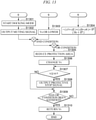
- FIG. 8 is a flowchart illustrating a step of switching of the protection area 401 and the threshold value of protective stop velocity, which is performed by the omnidirectional movable body 1 according to the first embodiment.
- the velocity monitoring module 32 waits until the velocity of the omnidirectional movable body 1 becomes equal to or lower than the low velocity value Vs (for example, 0.3 m/s).
- the velocity monitoring module 32 waits until the velocity calculated using Equation (1) becomes equal to or lower than the threshold value of the velocity, or waits until all of the rotational velocities ⁇ 1 to ⁇ 4 of the mecanum wheels 11a to 11d detected by the rotational velocity detectors 13a to 13d become lower than the threshold value N (for example, 0.3 rad/s).
- the velocity monitoring module 32 When the velocity of the omnidirectional movable body 1 becomes the low velocity value Vs or lower, the velocity monitoring module 32 outputs the switching signal for switching the range of the protection area 401 to the safety laser scanner 31. Accordingly, the safety laser scanner 31 reduces (or invalidates) the protection area 401 (step S802).
- the velocity monitoring module 32 changes the threshold value of protective stop velocity Vt from the first threshold value of protective stop velocity (1.1 m/s) to the second threshold value of protective stop velocity (0.3 m/s) (step S803).
- changing the threshold value of protective stop velocity Vt to the second protective stop velocity is not limited to the velocity of the omnidirectional movable body 1 being equal to or lower than the low velocity value Vs, and may be performed when a muting signal is output from the main controller 22.
- the velocity monitoring module 32 determines whether or not the current movement velocity V of the omnidirectional movable body 1 is equal to or higher than the second threshold value of protective stop velocity (0.3 m/s) (step S804).
- the movement velocity V of the omnidirectional movable body 1 can be calculated by using, for example, the result of detecting the rotational velocity of each mecanum wheel 11 and Equation (1).
- step S804: NO When the current movement velocity V of the omnidirectional movable body 1 is lower than the second threshold value of protective stop velocity (0.3 m/s) (step S804: NO), the velocity monitoring module 32 proceeds to step S806.
- the velocity monitoring module 32 outputs the protective stop signal 43 to the circuit breaker 33 (step S805). Accordingly, the omnidirectional movable body 1 makes an protective stop.
- the velocity monitoring module 32 determines whether or not the reduction of the protection area 401 has been released (step S806).
- the reduction of the protection area 401 is released according to the movement plan.
- step S806: NO the velocity monitoring module 32 returns to step S804.
- step S806: YES the threshold value of protective stop velocity Vt is returned to the first threshold value of protective stop velocity (1.1 m/s) (step S807), and a series of steps end.
- the velocity monitoring module 32 may return the threshold value of protective stop velocity Vt to the first threshold value of protective stop velocity (1.1 m/s).
- the omnidirectional movable body 1 of the first embodiment described above when the omnidirectional movable body 1 travels at a low velocity (the low velocity value Vs or lower), it is possible to reduce the range of the protection area 401 of the safety laser scanner 31. This makes it possible to curb the safety laser scanner 31 detecting the transport target object 500 as an obstacle when the omnidirectional movable body 1 approaches the transport target object 500 and travels at a low velocity. Therefore, the omnidirectional movable body 1 can pick up the transport target object 500 (crawl under the transport target object 500) and can transport the transport target object 500.
- the omnidirectional movable body 1 since the range of the protection area 401 can be reduced by using the rotational velocity of the mecanum wheel 11 without providing a plurality of sensors for detecting obstacles, it is possible to control the safety control system Sf with a simple configuration. Therefore, it is possible to safely operate the omnidirectional movable body 1 with a simple configuration.
- the omnidirectional movable body 1 of the first embodiment when the protection area 401 is reduced, it is possible to curb the omnidirectional movable body 1 operating at a movement velocity equal to or higher than the second threshold value of protective stop velocity. That is, it is possible to curb the omnidirectional movable body 1 operating at a movement velocity equal to or higher than the second threshold value of protective stop velocity when the omnidirectional movable body 1 approaches the transport target object 500 and travels at a low velocity. Therefore, it is possible to curb the omnidirectional movable body 1 coming into contact with the transport target object 500 or the like, and to safely operate the omnidirectional movable body 1.
- the threshold value of protective stop velocity is not decreased, making it difficult for the omnidirectional movable body 1 to make an protective stop. Therefore, it is possible to curb a decrease in movement efficiency of the omnidirectional movable body 1.
- FIG. 9 is a diagram illustrating a logic for switching of the protection area 401 and the threshold value of protective stop velocity according to modification example 1 of the first embodiment.
- the logic 900 illustrated in FIG. 9 is a logic that outputs a logical product of the output result of the logic 700 and the operation signal from the main controller 22.
- the operation signal from the main controller 22 is a signal that is output from the main controller 22 according to a target movement plan, for example, when the omnidirectional movable body 1 docks (an operation at the time of pick-up) with the transport target object 500 (basket cart).
- the velocity monitoring module 32 outputs a signal for reducing the protection area 401.
- the velocity monitoring module 32 changes the threshold value of protective stop velocity from the first threshold value of protective stop velocity (1.1 m/s) to the second threshold value of protective stop velocity (0.3 m/s).
- FIG. 10 is a sequence diagram illustrating a step of switching of the protection area 401 and the threshold value of protective stop velocity, which is performed by the omnidirectional movable body 1 according to modification example 1 of the first embodiment.
- the main controller 22 refers to the movement plan and waits until the docking mode, which indicates the start of transport of the transport target object 500 of the omnidirectional movable body 1, is started.
- the main controller 22 outputs an operation signal (for example, a muting signal) to the velocity monitoring module 32 (step S1002).
- step S1003 the velocity monitoring module 32 waits until the velocity of the omnidirectional movable body 1 becomes the low velocity value Vs or lower. Specifically, the velocity monitoring module 32 waits until all of the rotational velocities ⁇ 1 to ⁇ 4 of the mecanum wheels 11a to 11d detected by the rotational velocity detectors 13a to 13d become lower than the threshold value N.
- the velocity of the omnidirectional movable body 1 may be calculated by using the detection result of the rotational velocity of each mecanum wheel 11 and Equation (1).
- the velocity monitoring module 32 When the velocity of the omnidirectional movable body 1 becomes the low velocity value Vs or lower and the operation signal is input from the main controller 22, that is, when the AND condition is satisfied, the velocity monitoring module 32 outputs the switching signal for switching the range of the protection area 401 to the safety laser scanner 31. Accordingly, the safety laser scanner 31 reduces (or invalidates) the protection area 401 (step S1004).
- the velocity monitoring module 32 changes the threshold value of protective stop velocity Vt from the first threshold value of protective stop velocity (1.1 m/s) to the second threshold value of protective stop velocity (0.3 m/s) (step S1005).
- a condition for changing the threshold value of protective stop velocity Vt to the second protective stop velocity is not limited to the satisfaction of the AND condition and may be that the muting signal is output from the main controller 22.
- the velocity monitoring module 32 determines whether or not the current movement velocity V of the omnidirectional movable body 1 is equal to or higher than the second threshold value of protective stop velocity (0.3 m/s) (step S1006).
- the movement velocity V of the omnidirectional movable body 1 can be calculated by using, for example, the result of detecting the rotational velocity of each mecanum wheel 11 and Equation (1).
- step S1006 When the current movement velocity V of the omnidirectional movable body 1 is lower than the second threshold value of protective stop velocity (0.3 m/s) (step S1006: NO), the velocity monitoring module 32 proceeds to step S1008.
- step S1008 When the current movement velocity V of the omnidirectional movable body 1 is equal to or higher than the second threshold value of protective stop velocity (0.3 m/s) (step S1006: YES), the velocity monitoring module 32 outputs the protective stop signal 43 to the circuit breaker 33 (step S1007). Accordingly, the omnidirectional movable body 1 makes an protective stop.
- the velocity monitoring module 32 determines whether or not the satisfaction of the AND condition has ended (step S1008). When the satisfaction of the AND condition has not ended (step S1008: NO), the velocity monitoring module 32 returns to step S1006. When the satisfaction of the AND condition has ended (step S1008: YES), the reduction of the protection area 401 is released, the threshold value of protective stop velocity Vt is returned to the first threshold value of protective stop velocity (1.1 m/s) (step S1009), and the series of steps end. When the condition for changing the threshold value of protective stop velocity Vt to the second protective stop velocity is the output of the muting signal, a determination may be made as to whether or not the output of the muting signal from the main controller 22 has stopped in step S1008. When the output of the signal is stopped, the velocity monitoring module 32 may return the threshold value of protective stop velocity Vt to the first threshold value of protective stop velocity (1.1 m/s).
- the omnidirectional movable body 1 when the docking mode is started and the omnidirectional movable body 1 travels at a low velocity (the low velocity value Vs or lower) near a position in which the transport target object 500 is disposed, it is possible to prevent the safety laser scanner 31 from detecting the transport target object 500 as an obstacle. That is, even when the omnidirectional movable body 1 travels at a low velocity, the protection area 401 can be prevented from being reduced except near the transport target object 500. Therefore, the range of the protection area 401 is reduced at an inappropriate position other than near the transport target object 500, making it possible to curb degradation of the safety. Further, since the range of the protection area 401 can be reduced at a more appropriate timing, it is possible to improve the efficiency of the transport that is performed by the omnidirectional movable body 1.
- Vs or lower the low velocity value
- the calculation value referred to here is the main movement velocity Vx of the omnidirectional movable body 1 in the x direction (also referred to as a "main traveling direction").
- Vx main movement velocity
- Whether or not the omnidirectional movable body 1 retreats with respect to the main traveling direction can be determined using Equation (4). [Math. 4] ⁇ ⁇ 1 + ⁇ 2 + ⁇ 3 + ⁇ 4 ⁇ 0
- Equation (4) The left side of Equation (4) indicates the main movement velocity Vx.
- FIG. 11 is a diagram illustrating a logic for switching of the protection area 401 and the threshold value of protective stop velocity according to modification example 2 of the first embodiment.
- the logic 1100 illustrated in FIG. 11 is a logic that outputs a logical sum (a result of the OR condition) of the output result of the logic 700 and a result of the determination that the omnidirectional movable body 1 retreats.
- the velocity monitoring module 32 uses this logic 1100 to output a signal for reducing the protection area 401 when the OR condition thereof is satisfied.
- the velocity monitoring module 32 changes the threshold value of protective stop velocity from the first threshold value of protective stop velocity (1.1 m/s) to the second threshold value of protective stop velocity (0.3 m/s).
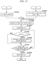
- FIG. 12 is a sequence diagram illustrating a step of switching of the protection area 401 and the threshold value of protective stop velocity, which is performed by the omnidirectional movable body 1 according to modification example 2 of the first embodiment.
- the velocity monitoring module 32 waits until the velocity of the omnidirectional movable body 1 becomes the low velocity value Vs or lower. Specifically, the velocity monitoring module 32 waits until all of the rotational velocities ⁇ 1 to ⁇ 4 of the mecanum wheels 11a to 11d detected by the rotational velocity detectors 13a to 13d become lower than the threshold value N.
- the velocity of the omnidirectional movable body 1 may be calculated by using the detection result of the rotational velocity of each mecanum wheel 11 and Equation (1).
- step S1202 the velocity monitoring module 32 waits until the main movement velocity Vx, which indicates that the omnidirectional movable body 1 retreats, becomes lower than 0 (until -( ⁇ 1 + ⁇ 2) + ( ⁇ 3 + ⁇ 4) ⁇ 0 is satisfied).
- the velocity monitoring module 32 outputs the switching signal for switching the range of the protection area 401 to the safety laser scanner 31. Accordingly, the safety laser scanner 31 reduces (or invalidates) the protection area 401 (step S1203).
- the velocity monitoring module 32 changes the threshold value of protective stop velocity Vt from the first threshold value of protective stop velocity (1.1 m/s) to the second threshold value of protective stop velocity (0.3 m/s) (step S1204).
- the condition for changing the threshold value of protective stop velocity Vt to the second protective stop velocity is not limited to the satisfaction of the OR condition, and may be that the muting signal may be output from the main controller 22.
- the velocity monitoring module 32 determines whether or not the current movement velocity V of the omnidirectional movable body 1 is equal to or higher than the second threshold value of protective stop velocity (0.3 m/s) (step S1205).
- the movement velocity V of the omnidirectional movable body 1 can be calculated by using, for example, the result of detecting the rotational velocity of each mecanum wheel 11 and Equation (1).
- step S1205: NO When the current movement velocity V of the omnidirectional movable body 1 is lower than the second threshold value of protective stop velocity (0.3 m/s) (step S1205: NO), the velocity monitoring module 32 proceeds to step S1207.
- the velocity monitoring module 32 outputs the protective stop signal 43 to the circuit breaker 33 (step S1206). Accordingly, the omnidirectional movable body 1 makes an protective stop.
- the velocity monitoring module 32 determines whether or not the OR condition has been satisfied (step S1207). When the satisfaction of the OR condition does not end (step S1207: NO), the velocity monitoring module 32 returns to step S1205. When the satisfaction of the OR condition ends (step S1207: YES), the reduction of the protection area 401 is released, the threshold value of protective stop velocity Vt is returned to the first threshold value of protective stop velocity (1.1 m/s) (step S1208), and the series of steps end.
- the condition for changing the threshold value of protective stop velocity Vt to the second protective stop velocity is the output of the muting signal, a determination may be made as to whether or not the output of the muting signal from the main controller 22 has stopped in step S1207. When the output of the signal is stopped, the velocity monitoring module 32 may return the threshold value of protective stop velocity Vt to the first threshold value of protective stop velocity (1.1 m/s).
- the range of the protection area 401 it is possible to reduce the range of the protection area 401 not only when the movement velocity of the omnidirectional movable body 1 decreases (the low velocity value Vs or lower), but also when the omnidirectional movable body 1 retreats.
- the omnidirectional movable body 1 retreats near the transport target object 500
- the omnidirectional movable body 1 is oriented in a direction (facing direction) with respect to the transport target object 500
- the omnidirectional movable body 1 retreats near the transport target object 500 such as a case in which the omnidirectional movable body 1 is oriented in a direction (facing direction) with respect to the transport target object 500, it is possible to curb a backward movement velocity of the omnidirectional movable body 1 becoming a movement velocity equal to or higher than the second threshold value of protective stop velocity, and thus, to safely operate the omnidirectional movable body 1.
- the velocity monitoring module 32 may changes only the threshold value of protective stop velocity in the backward direction to the second threshold value of protective stop velocity (0.3 m/s). Specifically, the velocity monitoring module 32 discriminates whether or not the omnidirectional movable body 1 retreats, and when the velocity monitoring module 32 discriminates that the omnidirectional movable body 1 retreats, the threshold value of protective stop velocity may be changed only in the backward direction. Accordingly, it is possible to curb the omnidirectional movable body 1 operating at a movement velocity equal to or higher than the second threshold value of protective stop velocity only in the backward direction.
- the threshold value of protective stop velocity is not decreased except for backward, it is possible to make it difficult for the omnidirectional movable body 1 to make an protective stop except for backward side. Therefore, it is possible to further curb the degradation in the movement efficiency of the omnidirectional movable body 1.
- FIG. 13 is a sequence diagram illustrating a step of switching of the protection area 401 and the threshold value of protective stop velocity, which is performed by the omnidirectional movable body 1 according to modification example 3 of the first embodiment.
- the main controller 22 refers to the movement plan and waits until the docking mode, which indicates the start of transport of the transport target object 500 of the omnidirectional movable body 1, is started.
- the main controller 22 outputs the operation signal (for example, the muting signal) to the velocity monitoring module 32 (step S1302).
- step S1303 the velocity monitoring module 32 waits until the velocity of the omnidirectional movable body 1 becomes the low velocity value Vs or lower. Specifically, the velocity monitoring module 32 waits until all of the rotational velocities ⁇ 1 to ⁇ 4 of the mecanum wheels 11a to 11d detected by the rotational velocity detectors 13a to 13d become lower than the threshold value N.
- the velocity of the omnidirectional movable body 1 may be calculated by using the detection result of the rotational velocity of each mecanum wheel 11 and Equation (1).
- step S1304 the velocity monitoring module 32 waits until the main movement velocity Vx, which indicates that the omnidirectional movable body 1 retreats, becomes lower than 0 (until -( ⁇ 1 + ⁇ 2) + ( ⁇ 3 + ⁇ 4) ⁇ 0 is satisfied).
- the velocity monitoring module 32 outputs the switching signal for switching the range of the protection area 401 to the safety laser scanner 31. Accordingly, the safety laser scanner 31 reduces (or invalidates) the protection area 401 (step S1305).
- the velocity monitoring module 32 changes the threshold value of protective stop velocity Vt from the first threshold value of protective stop velocity (1.1 m/s) to the second threshold value of protective stop velocity (0.3 m/s) (step S1306).
- the condition for changing the threshold value of protective stop velocity Vt to the second protective stop velocity is not limited to the satisfaction of the OR condition, and may be that the muting signal may be output from the main controller 22.
- the velocity monitoring module 32 determines whether or not the current movement velocity V of the omnidirectional movable body 1 is equal to or higher than the second threshold value of protective stop velocity (0.3 m/s) (step S1307).
- the movement velocity V of the omnidirectional movable body 1 can be calculated by using, for example, the result of detecting the rotational velocity of each mecanum wheel 11 and Equation (1).
- step S1307: NO When the current movement velocity V of the omnidirectional movable body 1 is lower than the second threshold value of protective stop velocity (0.3 m/s) (step S1307: NO), the velocity monitoring module 32 proceeds to step S1309.
- the velocity monitoring module 32 outputs the protective stop signal 43 to the circuit breaker 33 (step S1308). Accordingly, the omnidirectional movable body 1 makes an protective stop.
- the velocity monitoring module 32 determines whether or not the satisfaction of the OR conditions (1) and (2) has ended (step S1309). When the satisfaction of the OR conditions (1) and (2) has not ended (step S1309: NO), the velocity monitoring module 32 returns to step S1307. When the satisfaction of the OR conditions (1) and (2) has ended (step S1309: YES), the reduction of the protection area 401 is released, the threshold value of protective stop velocity Vt is returned to the first threshold value of protective stop velocity (1.1 m/s) (step S1310), and a series of steps end. In the present modification example 3, when the omnidirectional movable body 1 retreats, the velocity monitoring module 32 may change only the threshold value of protective stop velocity in the backward direction to the second threshold value of protective stop velocity (0.3 m/s).
- the velocity monitoring module 32 may return the threshold value of protective stop velocity Vt to the first threshold value of protective stop velocity (1.1 m/s).
- modification example 3 of the first embodiment it is possible to obtain the effects of both modification example 1 and modification example 2. That is, it is possible to curb degradation of the safety of the omnidirectional movable body 1, and to improve the efficiency of the transport that is performed by the omnidirectional movable body 1.
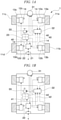
- FIG. 14 is a diagram illustrating a logic for switching the protection area 401 according to modification example 4 of the first embodiment.
- the logic 1400 illustrated in FIG. 14 is a logic that determines whether or not the rotational velocity of each wheel of the mecanum wheel 11 is equal to or lower than the same or different threshold value and outputs a logical product of results of the determination.
- Threshold values A1 to A4 and B1 to B4 set for each wheel illustrated in FIG. 14 are values for discriminating a specific operation before entrance to the docking mode.
- the velocity monitoring module 32 further waits until the rotational velocity ⁇ 1 becomes lower than the threshold value B1.
- the velocity monitoring module 32 further waits until the rotational velocities ⁇ 2 to ⁇ 4 become lower than the threshold values B2 to B4.
- the velocity monitoring module 32 When the conditions are sequentially satisfied for all of the rotational velocities ⁇ 1 to ⁇ 4 and all the two-step conditions illustrated in FIG. 14 are satisfied, that is, when the AND condition is satisfied, the velocity monitoring module 32 is regarded as having performed the specific operation before entrance to the docking mode. Therefore, the velocity monitoring module 32 outputs the switching signal for switching the range of the protection area 401 to the safety laser scanner 31. Accordingly, the safety laser scanner 31 reduces (or invalidates) the protection area 401. Further, the velocity monitoring module 32 changes the threshold value of protective stop velocity from the first threshold value of protective stop velocity (1.1 m/s) to the second threshold value of protective stop velocity (0.3 m/s). Whether or not the specific operation has been performed is not limited to being obtained from the logic, but can also be obtained from a calculation result using the detection result of the rotational velocity of each mecanum wheel 11 and Equation (1).
- the main controller 22 outputs an operation signal when a predetermined time has elapsed. Accordingly, the safety laser scanner 31 resets the reduction or invalidation of the protection area 401 or the change of the threshold value of protective stop velocity.
- the velocity monitoring module 32 may receive the operation signal from the main controller 22 and instruct the safety laser scanner 31 to perform resetting. That is, the safety laser scanner 31 may reset the reduction or invalidation of the protection area 401 or the change of the threshold value of protective stop velocity on the basis of the instruction from the velocity monitoring module 32. Further, the safety laser scanner 31 may directly receive an operation signal indicating the resetting from the main controller 22 and reset the reduction or invalidation of the protection area 401 or the change of the threshold value of protective stop velocity.
- the safety laser scanner 31 may reset the reduction or invalidation of the protection area 401 or the change of the threshold value of protective stop velocity on the basis of a measurement result of a timer.
- the timer may be provided in the velocity monitoring module 32 or may be provided in the safety laser scanner 31. Further, the timer may be able to measure a time required for an operation in the docking mode, for example.
- the safety laser scanner 31 may reset reduction or invalidation of the protection area 401 or the change of the threshold value of protective stop velocity on the basis of an instruction based on the measurement result of the timer from the velocity monitoring module 32.
- the omnidirectional movable body 1 when the omnidirectional movable body 1 performs the specific operation before entrance to the docking mode, it is possible to prevent the safety laser scanner 31 from detecting the transport target object 500 as an obstacle. Therefore, it is possible to reduce the range of the protection area 401 and to curb degradation of the safety. Further, since the range of the protection area 401 can be reduced at a more appropriate timing, it is possible to improve the efficiency of the transport that is performed by the omnidirectional movable body 1. Further, since it is possible to curb the omnidirectional movable body 1 being at a movement velocity equal to or higher than the second threshold value of protective stop velocity near the transport target object 500, it is possible to safely operate the omnidirectional movable body 1.
- modification example 4 of the first embodiment it is possible to discriminate that the operation is the specific operation before entrance to the docking mode without using the operation signal from the main controller 22, and to change the range of the protection area 401 and the threshold value of protective stop velocity. This makes it possible to curb a load related to the output of the operation signal that is performed by the main controller 22.
- Modification example 4 of the first embodiment may be applied to the modification 1 of the first embodiment. That is, the range of the protection area 401 and the threshold value of protective stop velocity may be changed by using the operation signal output from the main controller 22. Specifically, the range of the protection area 401 and the threshold value of protective stop velocity may be changed according to the logical product of "the logical product of the rotational velocities ⁇ 1 to ⁇ 4 satisfying all the two-step conditions illustrated in FIG. 14 " and "the operation signal output from the main controller 22".
- the omnidirectional movable body 1 when the omnidirectional movable body 1 performs the specific operation (when performing docking with the transport target object 500) at a position in which the transport target object 500 is disposed, it is possible to prevent the safety laser scanner 31 from detecting the transport target object 500 as an obstacle. Therefore, it is possible to curb the safety being degraded due to reduction of the range of the protection area 401 at an inappropriate position. Further, since the range of the protection area 401 can be reduced at a more appropriate timing, it is possible to improve the efficiency of the transport that is performed by the omnidirectional movable body 1.
- the monitoring area is reduced (when the omnidirectional movable body 1 is docked with the transport target object 500), it is possible to curb the omnidirectional movable body 1 becoming at a movement velocity equal to or higher than the second threshold value of protective stop velocity, and thus, to safely operate the omnidirectional movable body 1.
- Equations (5) and (6) are used for detection of an abnormality in the rotational velocity of each wheel of the mecanum wheel 11.
- ⁇ 1 ⁇ ⁇ 2 ⁇ ⁇ 3 + ⁇ 4 h
- h > ⁇
- Equation (1) a relationship between ⁇ 1, ⁇ 2, ⁇ 3, ⁇ 4 and Vx, Vy, ⁇ is shown.
- Equation (1) ⁇ 1, ⁇ 2, ⁇ 3, and ⁇ 4 can theoretically have arbitrary values, but in reality, they cannot have arbitrary values due to a constraint condition between the road surface and the wheels.
- Equation (6) is an equation for determining that any value of ⁇ 1 to ⁇ 4 deviating from the constraint condition in Equation (1) has been input.
- FIG. 15 is a sequence diagram illustrating a step of switching of the protection area 401 and the threshold value of protective stop velocity, which is performed by the omnidirectional movable body 1 according to modification example 5 of the first embodiment.
- the velocity monitoring module 32 waits until the velocity of the omnidirectional movable body 1 becomes the low velocity value Vs or lower. Specifically, the velocity monitoring module 32 waits until all of the rotational velocities ⁇ 1 to ⁇ 4 of the mecanum wheels 11a to 11d detected by the rotational velocity detectors 13a to 13d become lower than the threshold value N.
- the velocity monitoring module 32 waits until an abnormality is detected, that is, until "
- the velocity monitoring module 32 determines whether or not the abnormality has lasted for a certain period of time in step S1503.
- an averaging filter is used to determine whether or not the abnormality has lasted for the certain period of time. This makes it possible to curb a rotation abnormality being determined and the omnidirectional movable body 1 being stopped due to noise or temporary wheel slippage.
- the velocity monitoring module 32 outputs the switching signal for switching the range of the protection area 401 to the safety laser scanner 31. Accordingly, the safety laser scanner 31 reduces (or invalidates) the protection area 401 (step S1504).
- the velocity monitoring module 32 outputs a protection stop signal for stopping the omnidirectional movable body 1.
- the protection stop signal is output from the velocity monitoring module 32 to the circuit breaker 33 directly or to the circuit breaker 33 via other devices (the main controller 22, the motor control circuit 23, the safety laser scanner 31, and the like).
- the drive motor 12 is stopped (step S1505), and a series of steps ends.
- the velocity monitoring module 32 changes the threshold value of protective stop velocity Vt from the first threshold value of protective stop velocity (1.1 m/s) to the second threshold value of protective stop velocity (0.3 m/s) (step S1506).
- a condition for changing the threshold value of protective stop velocity Vt to the second protective stop velocity is not limited to the satisfaction of the AND condition and may be that the muting signal is output from the main controller 22.
- the velocity monitoring module 32 determines whether or not the current movement velocity V of the omnidirectional movable body 1 is equal to or higher than the second threshold value of protective stop velocity (0.3 m/s) (step S1507).
- the movement velocity V of the omnidirectional movable body 1 can be calculated by using, for example, the result of detecting the rotational velocity of each mecanum wheel 11 and Equation (1).
- step S1507: NO When the current movement velocity V of the omnidirectional movable body 1 is lower than the second threshold value of protective stop velocity (0.3 m/s) (step S1507: NO), the velocity monitoring module 32 proceeds to step S1509.
- the velocity monitoring module 32 outputs the protective stop signal 43 to the circuit breaker 33 (step S1508). Accordingly, the omnidirectional movable body 1 makes an protective stop.
- the velocity monitoring module 32 determines whether or not the AND condition has ended (step S1509). When the AND condition has not ended (step S1509: NO), the velocity monitoring module 32 returns to step S1507. When the AND condition has ended (step S1509: YES), the reduction of the protection area 401 is released, the threshold value of protective stop velocity Vt is returned to the first threshold value of protective stop velocity (1.1 m/s) (step S1510), and a series of steps end.
- the condition for changing the threshold value of protective stop velocity Vt to the second protective stop velocity is the output of the muting signal, a determination may be made as to whether or not the output of the muting signal from the main controller 22 has stopped in step S1509. When the output of the signal is stopped, the velocity monitoring module 32 may return the threshold value of protective stop velocity Vt to the first threshold value of protective stop velocity (1.1 m/s).
- modification example 5 when the rotation abnormality of the wheel is detected for a certain period of time, the omnidirectional movable body 1 is stopped. Therefore, it is possible to curb the omnidirectional movable body 1 being stopped by determining that there is a rotation abnormality of the wheel due to noise or temporary wheel slippage. This makes it possible to improve the efficiency of the transport that is performed by the omnidirectional movable body 1.
- FIG. 16 is a diagram illustrating an example of a coordinate system of an omnidirectional movable body 1600 and omni-wheels 1601a to 1601d.
- the omni-wheels 1601a to 1601d are simply referred to as an "omni-wheel 1601" when it is not necessary to distinguish the omni-wheels 1601a to 1601d.
- the omnidirectional movable body 1600 includes four omni-wheels 1601. In the four omni-wheels 1601, an axle connecting the omni-wheel 1601a to the omni-wheel 1601d and an axle connecting the omni-wheel 1601b to the omni-wheel 1601c pass through a center of the omnidirectional movable body 1600 and are disposed at an angle of 90°.
- a traveling direction (forward direction) of the omnidirectional movable body 1600 is defined as an x-axis
- a lateral direction is defined as a y-axis
- a direction perpendicular to a paper surface is defined as a z-axis (not illustrated).
- a top direction in FIG. 16 is a positive direction.
- a left direction in FIG. 16 is a positive direction.
- a counterclockwise direction in FIG. 16 is a positive direction.
- a velocity of the omnidirectional movable body 1600 in the forward direction is defined as Vx.
- a velocity of the omnidirectional movable body 1600 in the lateral direction is defined as Vy.
- a turning velocity of the omnidirectional movable body 1600 is defined as ⁇ .
- each omni-wheel 1601 For a rotation direction of each omni-wheel 1601, a counterclockwise direction toward a direction in which the omni-wheel 1601 is attached to the omnidirectional movable body 1600 (a center of the omnidirectional movable body 1600) is positive (plus). Further, a rotational velocity of the wheel of the omni-wheel 1601a is ⁇ 1, a rotational velocity of the wheel of the omni-wheel 1601b is ⁇ 2, a rotational velocity of the wheel of the omni-wheel 1601c is ⁇ 3, and a rotational velocity of the wheel of the omni-wheel 1601d is ⁇ 4.
- Equations (1) to (3) described above can be applied to the omni-wheel 1601, similar to the mecanum wheel 11 described in the first embodiment. Therefore, the main controller 22 can output the calculated target rotational velocity to the motor control circuit 23 to move the omnidirectional movable body 1600 at a desired velocity in a desired direction.
- Equation (4) described above, similar to modification example 2 of the first embodiment.
- the presence or absence of an abnormality in the rotational velocity of each omni-wheel 1601 can be determined using Equations (5) and (6) described above, similar to modification example 5 of the first embodiment.
- the omnidirectional movable body 1600 using the omni-wheel 1601 according to the second embodiment it is possible to achieve the same effects as those of the omnidirectional movable body 1 using the mecanum wheel 11 shown in the first embodiment. Further, in the second embodiment, each of the modification examples shown in modification examples 1 to 5 of the first embodiment can be applied.
- FIG. 17 is a diagram illustrating an example of a coordinate system of the omnidirectional movable body 1700 and the omni-wheels 1701a to 1701c.
- the omni-wheels 1701a to 1701c are simply referred to as an "omni-wheel 1701" when it is not necessary to distinguish the omni-wheels 1701a to 1701c.
- the omnidirectional movable body 1700 includes three omni-wheels 1701.
- the three omni-wheels 1701 are disposed so that respective axles thereof pass through the center of the omnidirectional movable body 1700. Further, the three omni-wheels 1701 are disposed so that a distance between the axles form an angle of 120°.
- a traveling direction (forward direction) of the omnidirectional movable body 1700 is defined as an x-axis
- a lateral direction is defined as a y-axis
- a direction perpendicular to a paper surface is defined as a z-axis (not illustrated).
- a top direction in FIG. 17 is a positive direction.
- a left direction in FIG. 17 is a positive direction.
- a counterclockwise direction in FIG. 17 is a positive direction.
- a velocity of the omnidirectional movable body 1700 in the forward direction is defined as Vx.
- a velocity of the omnidirectional movable body 1700 in the lateral direction is defined as Vy.
- a turning velocity of the omnidirectional movable body 1700 is defined as ⁇ .
- each omni-wheel 1701 For a rotation direction of each omni-wheel 1701, a counterclockwise direction toward a direction in which the omni-wheel 1701 is attached to the omnidirectional movable body 1700 (a center of the omnidirectional movable body 1700) is positive (plus). Further, a rotational velocity of the wheel of the omni-wheel 1701a is ⁇ 1, a rotational velocity of the wheel of the omni-wheel 1701b is ⁇ 2, and a rotational velocity of the wheel of the omni-wheel 1701c is ⁇ 3.
- Equation (7) is an equation called forward kinematics.
- C is a 3 ⁇ 3 matrix.
- Rw indicates a wheel radius
- Matrix components include a coefficient related to a wheel disposition of the omni-wheel 1701.
- D is a 3 ⁇ 3 matrix.
- Matrix components include a wheel diameter of the omni-wheel 1701 or a coefficient related to a wheel disposition.
- the main controller 22 calculates target rotational velocities of the three omni-wheels 1701 from the target velocities of the omnidirectional movable body 1700 using the relationships of Equations (7) and (8).
- the main controller 22 outputs the calculated target rotational velocity to the motor control circuit 23 so that the omnidirectional movable body 1700 is moved at a desired velocity in a desired direction.
- FIG. 18 is a diagram illustrating a velocity determination logic according to the third embodiment.
- a logic 1800 illustrated in FIG. 18 is a logic that determines whether or not the rotational velocity of each omni-wheel 1701 is equal to or lower than a threshold value and outputs a logical product of results of the determinations.
- the logic 1800 indicates a logic that outputs a switching signal for the protection area 401 when all of the rotational velocities ⁇ 1 to ⁇ 3 is lower than the threshold value Q, that is, when the AND condition is satisfied.
- All of the rotational velocities ⁇ 1 to ⁇ 3 of the omni-wheels 1701a to 1701c detected by the rotational velocity detectors 13a to 13d being lower than the threshold value Q indicates that the omnidirectional movable body 1700 is below the threshold value (at a low velocity). That is, a result of outputting the logical product in the logic 1800 indicates that the omnidirectional movable body 1700 is below the threshold value (at a low velocity).
- the velocity monitoring module 32 When all of the rotational velocities ⁇ 1 to ⁇ 3 are lower than the threshold value Q, the velocity monitoring module 32 outputs the switching signal for switching the range of the protection area 401 to the safety laser scanner 31. Accordingly, the safety laser scanner 31 can reduce the range of the protection area 401 when the omnidirectional movable body 1700 travels at a low velocity. Further, when all of the rotational velocities ⁇ 1 to ⁇ 3 are lower than the threshold value Q, the velocity monitoring module 32 changes the threshold value of protective stop velocity from the first threshold value of protective stop velocity (1.1 m/s) to the second threshold value for protective stop velocity (0.3 m/s).
- the change of the threshold value of protective stop velocity to the second protective stop velocity is not limited to the velocity of the omnidirectional movable body 1700 being equal to or lower than the low velocity value Vs and may be performed when the muting signal is output from the main controller 22.
- the respective rotational velocities of the three omni-wheels 1701a to 1701c are detected, and when all of the rotational velocities are equal to or lower than the threshold value, a discrimination is made that the omnidirectional movable body 1700 is traveling at a low velocity, but the present invention is not limited thereto.
- the movement velocity may be calculated using the detection results of the rotational velocities of the omni-wheels 1701a to 1701c and Equation (7), and a discrimination may be made from the calculation results that the omnidirectional movable body 1700 is traveling at a low velocity.
- the omnidirectional movable body 1700 in which the three omni-wheels 1701 are used according to the third embodiment described above it is possible to achieve the same effects as those of the omnidirectional movable body 1 using the mecanum wheels 11 shown in the first embodiment.
- modification examples corresponding to modification examples 1, 3 to 5 of the first embodiment can be applied in the third embodiment.
- a case in which the range of the protection area 401 is reduced according to the logical product of "the logical product of the rotational velocities of the respective wheels being equal to or lower than the threshold value" and "the result of the detecting the rotation abnormality" shown in modification example 5 of the first embodiment will be supplemented.
- the rotational velocity of each wheel can be arbitrarily set, so that the abnormality in the number of rotations cannot be detected only from the rotational velocity of each of the three omni-wheels 1701. That is, it is not possible to obtain equations corresponding to Equations (5) and (6) shown in modification example 5 of the first embodiment.
- the omnidirectional movable body 1700 including the three omni-wheels 1701 the range of the protection area 401 and the threshold value of protective stop velocity can be changed according to the logical product of "the logical product of the rotational velocities of the respective wheels being equal to or lower than the threshold value" and "the result of the detecting the rotation abnormality".
- modification example 1 of the third embodiment An example corresponding to modification example 2 of the first embodiment will be described in modification example 1 of the third embodiment.
- the third embodiment described above a case in which the range of the protection area 401 is reduced according to the result of outputting the logical product in which the result of determining the rotational velocity of each wheel has been used has been described.
- a case in which the range of the protection area 401 and the threshold value of protective stop velocity are changed according to a logical sum of "the logical product of the rotational velocities of the respective wheels being equal to or lower than the threshold value" and "the calculation value calculated using the rotational velocity of each omni-wheel 1701" will be described in modification example 1 of the third embodiment.
- Equation (9) indicates an equation for determining the velocity of the omnidirectional movable body 1 with respect to the main traveling direction. [Math. 9] k 1 ⁇ ⁇ 1 + k 2 ⁇ ⁇ 2 + k 3 ⁇ ⁇ 3 ⁇ m
- m is a determination threshold value.
- k1, k2, and k3 are all appropriate coefficients.
- Equation (9) is expressed as Equation (10). [Math. 10] ⁇ ⁇ 2 + ⁇ 3 ⁇ m
- a logic that outputs a logical sum (a result of an OR condition) of the output result of the logic 1800 illustrated in FIG. 18 and the determination result in which the calculation value calculated by using the respective rotational velocities of the omni-wheels 1701 has been used is used.
- the velocity monitoring module 32 outputs a signal for reducing the protection area 401 when the OR condition thereof is satisfied. Accordingly, the omnidirectional movable body 1 can reduce the range of the protection area 401. Further, when the OR condition thereof is satisfied, the velocity monitoring module 32 can change the threshold value of protective stop velocity to the second threshold value of protective stop velocity. In modification example 1 according to the third embodiment, when the omnidirectional movable body 1 retreats, the velocity monitoring module 32 may change only the threshold value of protective stop velocity in the backward direction to the second threshold value for protective stop velocity (0.3 m/s).
- the range of the protection area 401 it is possible to reduce the range of the protection area 401 not only when the movement velocity of the omnidirectional movable body 1700 decreases, but also when the omnidirectional movable body 1700 retreats, for example.
- the omnidirectional movable body 1700 retreats near the transport target object 500 such as a case in which the omnidirectional movable body 1 is oriented in a direction (facing direction) with respect to the transport target object 500
- the threshold value of protective stop velocity Vt it is possible to decrease the threshold value of protective stop velocity Vt not only when the movement velocity of the omnidirectional movable body 1700 decreases (the low velocity value Vs or lower), but also when the omnidirectional movable body 1 retreats.
- the omnidirectional movable body 1 retreats near the transport target object 500
- an area to be monitored may be limited as in a case in which the omnidirectional movable body 1 performs a determined operation, such as orientation in a direction (facing direction) with respect to the transport target object 500, near the transport target object 500. Further, for example, when the omnidirectional movable body 1 that has finished work is disposed along a wall, the protection area 401 may be reduced only on one side surface.
- the velocity monitoring module 32 can change the threshold value of protective stop velocity to a different velocity according to the traveling direction of the omnidirectional movable body 1. Specifically, the velocity monitoring module 32 can set a direction in which the velocity monitoring module 32 changes the threshold value of protective stop velocity to the second threshold value of protective stop velocity to only a right direction or to only a backward direction on the basis of the movement plan.
- the velocity monitoring module 32 may reduce only a right direction of the monitoring area 400 (for example, the protection area 401) when changing the threshold value of protective stop velocity in only the right direction to the second threshold value of protective stop velocity. That is, a direction in which the range of the monitoring area 400 is reduced may be a direction according to the traveling direction of the omnidirectional movable body 1.
- the velocity monitoring module 32 may decrease the threshold value of protective stop velocity in a direction according to a calculation result indicating a moving state of the omnidirectional movable body 1. Specifically, for example, when a determination is made from the calculation result using Equation (4) that the omnidirectional movable body 1 is retreating, the velocity monitoring module 32 may decrease the threshold value of protective stop velocity only in the backward direction.
- FIG. 19 is a flowchart illustrating a step of changing the threshold value of protective stop velocity in the specific direction, which is performed by the omnidirectional movable body 1 according to the fourth embodiment.
- the main controller 22 refers to the movement plan and waits until the docking mode indicating the start of transport of the transport target object 500 of the omnidirectional movable body 1 is started or a predetermined operation such as disposing the omnidirectional movable body 1 that has finished the work at a predetermined position is started.
- the main controller 22 outputs an operation signal (for example, a muting signal) to the velocity monitoring module 32 (step S1902). It is assumed that this operation signal includes information indicating a moving direction of the omnidirectional movable body 1.
- the velocity monitoring module 32 When the operation signal is input from the main controller 22, the velocity monitoring module 32 outputs the switching signal for switching the range of the protection area 401 to the safety laser scanner 31. Accordingly, the safety laser scanner 31 reduces (or invalidates) the protection area 401 (step S1903).
- the velocity monitoring module 32 changes the threshold value of protective stop velocity Vt from the first threshold value of protective stop velocity (1.1 m/s) to the second threshold value of protective stop velocity (0.3 m/s) in the specific direction (for example, right direction) indicated by the movement plan (for example, the operation signal) (step S1904). Further, the velocity monitoring module 32 determines whether or not the current movement velocity V of the omnidirectional movable body 1 is equal to or higher than the second threshold value of protective stop velocity (0.3 m/s) in the specific direction (step S1905).
- the movement velocity V of the omnidirectional movable body 1 can be calculated by using, for example, the result of detecting the rotational velocity of each mecanum wheel 11 and Equation (1).
- step S1905: NO When the current movement velocity V of the omnidirectional movable body 1 is lower than the second threshold value of protective stop velocity (0.3 m/s) in the specific direction (step S1905: NO), the velocity monitoring module 32 proceeds to step S1907.
- the velocity monitoring module 32 outputs the protective stop signal 43 to the circuit breaker 33 (step S1906). Accordingly, the omnidirectional movable body 1 makes an protective stop.
- the velocity monitoring module 32 determines whether or not the reduction of the protection area 401 has been released (step S1907).
- the release of the reduction of the protection area 401 is performed according to the movement plan and, for example, the output of the operation signal (muting signal) from the main controller 22 ends.
- the velocity monitoring module 32 returns to step S1905.
- the threshold value of protective stop velocity Vt in the specific direction is returned to the first threshold value of protective stop velocity (1.1 m/s) (step S1908), and a series of steps end.
- FIG. 20 is a diagram illustrating an example of the threshold value of protective stop velocity according to the fourth embodiment.
- a state in which the protection area 401 is reduced in front of the omnidirectional movable body 1 is shown.
- the protection area 401 may be invalid.
- a threshold value of protective stop velocity for forward is 1.1 m/s
- threshold values of protective stop velocity for left, right, backward are 0.3 m/s. That is, it is shown that when the protection area 401 is reduced, the omnidirectional movable body 1 makes an protective stop when the movement velocity of the omnidirectional movable body 1 reaches 0.3 m/s in the left-right and backward directions. Further, it is shown that the omnidirectional movable body 1 makes an protective stop when the movement velocity of the omnidirectional movable body 1 reaches 1.1 m/s in the forward direction.
- FIG. 21 is a diagram illustrating another example of the threshold value of protective stop velocity according to the fourth embodiment.
- the protection area 401 can also be reduced for a specific area according to the movement plan.
- the threshold value of protective stop velocity is 0.5 m/s for forward, 0.3 m/s for diagonally right forward, 0.2 m/s for right, 0.5 m/s for left, and 0.2 m/s for backward. That is, it is shown that when the protection area 401 is reduced, for example, when the movement velocity of the omnidirectional movable body 1 reaches 0.3 m/s forward diagonally to the right, an protective stop is made.
- the omnidirectional movable body 1 of the fourth embodiment described above it is possible to reduce the range of the protection area 401 of the safety laser scanner 31 and decrease the threshold value of protective stop velocity Vt according to the operation signal from the main controller 22. Accordingly, the protection area 401 can be reduced when the vehicle approaches the transport target object 500 and travels at a low velocity, and it is possible to curb the omnidirectional movable body 1 operating at a movement velocity equal to or higher than the second threshold value of protective stop velocity. Therefore, it is possible to curb the omnidirectional movable body 1 coming into contact with the transport target object 500 or the like, and to safely operate the omnidirectional movable body 1.
- the omnidirectional movable body 1 of the fourth embodiment it is possible to decrease the threshold value of protective stop velocity Vt in the specific direction. Therefore, since the threshold value of protective stop velocity is not decreased in directions other than the specific direction, it is possible to make it difficult for the omnidirectional movable body 1 to make an protective stop. Therefore, it is possible to more effectively curb the degradation in the movement efficiency of the omnidirectional movable body 1.
- the omnidirectional movable body 1 or the like include drive wheels, a movement velocity detection unit, an object detection unit, a movement control unit, a changing unit, and a stopping unit.
- the drive wheels are three or more drive wheels for moving the omnidirectional movable body 1 or the like in all directions, and are driven independently.
- the drive wheels for example, any of four mecanum wheels 11a to 11d (see FIG. 3 ), four omni-wheels 1601a to 1601d (see FIG. 16 ), and three omni-wheels 1701a to 1701c (see FIG. 17 ) can be used.
- a rotational velocity detection unit detects the rotational velocity of each of the drive wheels.
- the rotational velocity detection unit is realized by the rotational velocity detectors 13a to 13d (see FIG. 1A ).
- the rotary encoder has been used for the rotational velocity detection unit (rotational velocity detectors 13a to 13d), but the present invention is not limited thereto.
- another velocity sensor such as a tacho generator or a resolver may be used for the rotational velocity detection unit.
- a signal output from the rotational velocity detection unit may be an analog voltage value or may be a digital value obtained by converting the analog voltage value.
- the movement velocity detection unit detects the movement velocity of the movable body using the rotational velocity of each drive wheel.
- the movement velocity detection unit detects the movement velocity from a calculation result in which the rotational velocities ⁇ 1 to ⁇ 4 detected by the rotational velocity detector 13 and Equation (1) have been used.
- the movement velocity detection unit can detect the movement velocity from the logical product of the rotational velocities ⁇ 1 to ⁇ 4 detected by the rotational velocity detector 13. That is, when the low velocity value Vs and the second threshold value of protective stop velocity are set to the specific velocity (0.3 m/s), the movement velocity detection unit can detect the movement velocity from the logical product of the rotational velocities ⁇ 1 to ⁇ 4.
- the object detection unit detects an object within the monitoring area 400 set around the omnidirectional movable body 1 or the like.
- the object is an obstacle such as a person or an object.
- the monitoring area 400 includes the protection area 401 and the warning area 402.
- the object detection unit is realized by, for example, the safety laser scanner 31 (see FIG. 1A ).
- the object detection un the present invention is not limited to the safety laser scanner 31, and it is also possible to use a camera that images an object or use another sensor such as an ultrasonic sensor.
- a plurality of object detection units may be provided.
- the object detection unit may be provided on the left, right, or rear of the omnidirectional movable body 1 or the like.
- the movement control unit moves the omnidirectional movable body 1 or the like according to the movement plan.
- the movement control unit performs entire control of the omnidirectional movable body 1 or the like.
- the movement control unit is realized by, for example, the main controller 22.
- the stopping unit and the changing unit are realized by the velocity monitoring module 32, which is an example of the control device.
- the stopping unit stops the omnidirectional movable body 1 or the like when the movement velocity detected by the movement velocity detection unit reaches a threshold value of velocity (the threshold value of protective stop velocity).
- the stopping unit outputs the protective stop signal 43 to the circuit breaker 33 to stop the omnidirectional movable body 1 or the like ( FIG. 1A ).
- the changing unit changes the range of the monitoring area 400 and the threshold value of velocity of the omnidirectional movable body 1 or the like on the basis of the operation signal output from the movement control unit. Further, the changing unit changes the range of the monitoring area 400 and the threshold value of velocity on the basis of the operation signal and the movement velocity detected by the movement velocity detection unit.
- the movement velocity detected by the movement velocity detection unit is obtained on the basis of the respective rotational velocities of the drive wheels detected by the rotational velocity detection unit.
- the changing unit reduces the range of the protection area 401 in the monitoring area 400 set in the object detection unit, and changes the threshold value of protective stop velocity to the second threshold value of protective stop velocity.
- the changing unit may reduce the range of the protection area 401 and may not change the threshold value of protective stop velocity.
- the changing unit may change the range of the monitoring area 400 and the threshold value of velocity in a case in which the velocity of the omnidirectional movable body 1 or the like becomes the low velocity value Vs (for example, 0.3 m/s) or lower. Further, the changing unit can change the threshold value of protective stop velocity to a different velocity according to the traveling direction of the omnidirectional movable body 1 or the like.
- the stopping unit stops the omnidirectional movable body 1 or the like when the movement velocity detected by the movement velocity detection unit is equal to or higher than the second threshold value of protective stop velocity.
- the changing unit may change not only the range of the protection area 401, but also the range of the warning area 402. Further, the changing unit may change only the range of the protection area 401 and not change the range of the warning area 402, or may change only the range of the warning area 402 and not change the range of the protection area 401.
- the velocity monitoring module 32 (the changing unit) that changes the range of the monitoring area 400 (the protection area 401) and the threshold value of protective stop velocity on the basis of the operation signal from the main controller 22 is included. Accordingly, the range of the protection area 401 can be reduced and the threshold value of protective stop velocity can be changed with a simple configuration without providing a plurality of sensors or the like. Therefore, it is possible to curb the omnidirectional movable body 1 discriminating the transport target object 500 as an obstacle near the transport target object 500 and stopping. Further, when the protection area 401 is reduced, it is possible to curb the omnidirectional movable body 1 or the like being at a movement velocity equal to or higher than the threshold value of protective stop velocity. As a result, it is possible to improve the safety of the omnidirectional movable body 1 or the like. Therefore, it is possible to simply and appropriately operate the omnidirectional movable body 1 while ensuring the reliability of the safety control system Sf.
- the changing unit determines whether or not the rotational velocity of each drive wheel is equal to or lower than the predetermined value, and changes the range of the monitoring area 400 and the threshold value of protective stop velocity on the basis of a logical product of the results of the determinations. For example, when the AND condition (logical product) indicating that the rotational velocities of the respective mecanum wheels 11 are equal to or lower than the threshold value is satisfied as illustrated in FIG. 7 , the changing unit reduces the range of the protection area 401 and decrease the threshold value of protective stop velocity.
- the velocity monitoring module 32 (the changing unit and the stopping unit) is realized by hardware, for example.
- the velocity monitoring module 32 may be realized by software. That is, functions of the changing unit and the stopping unit may be realized by a CPU executing a predetermined program (a threshold value of velocity change program or a monitoring area change program).
- a predetermined program a threshold value of velocity change program or a monitoring area change program.
- a safety controller for which safety certification has been acquired is used.
- a normal controller, PC, sequencer, or the like can be used for the velocity monitoring module 32.
- the changing unit changes the range of the monitoring area 400 and the threshold value of protective stop velocity on the basis of the calculation value indicating the movement velocity of the omnidirectional movable body 1 or the like calculated using the respective rotational velocities of the drive wheels.
- the calculation value indicating the movement velocity of the omnidirectional movable body 1 or the like is, for example, the main movement velocity Vx shown on the left side of Equation (4) described above.
- the main movement velocity Vx becomes lower than 0, that is, when the omnidirectional movable body 1 retreats
- the changing unit reduces the range of the protection area 401 and changes the threshold value of protective stop velocity.
- the determination of the main movement velocity Vx is not limited to "lower than 0" and "lower than a predetermined velocity" may be used.
- the predetermined velocity referred to here may be a value smaller than the low velocity value Vs (for example, 0.3 m/s) indicating a low velocity of the omnidirectional movable body 1 or the like.
- the omnidirectional movable body 1 is at a lower velocity (the low velocity value Vs or lower) or retreats near the transport target object 500, such as a case in which the omnidirectional movable body 1 is oriented in a direction with respect to the transport target object 500 (a facing direction), it is possible to appropriately reduce the range of the protection area 401 and prevent the transport target object 500 from being detected as an obstacle. Further, when the protection area 401 is reduced, it is possible to curb the omnidirectional movable body 1 operating at a movement velocity equal to or higher than the second threshold value of protective stop velocity. Therefore, it is possible to improve the efficiency of the transport that is performed by the omnidirectional movable body 1 and to safely operate the omnidirectional movable body 1.
- the changing unit determines whether or not the rotational velocity of each drive wheel is equal to or higher than a predetermined value, and changes the range of the monitoring area 400 and the threshold value of protective stop velocity on the basis of a logical sum of a "logical product of the results of the determinations" and a "calculation value indicating the movement velocity of the omnidirectional movable body 1 or the like calculated using the rotational velocity of each drive wheel".
- the changing unit can reduce the range of the protection area 401 and changes the threshold value of protective stop velocity when a condition (OR condition) of any one of the omnidirectional movable body 1 or the like traveling at the low velocity value Vs (for example, 0.3 m/s) or lower or the main movement velocity Vx becoming lower than 0 is satisfied, as illustrated in FIG. 11 .
- the omnidirectional movable body 1 approaches the transport target object 500 and travels at a low velocity (the low velocity value Vs or lower), but also in a case in which the omnidirectional movable body 1 is at a lower velocity or retreats such as the omnidirectional movable body 1 is oriented in a direction with respect to the transport target object 500 (a facing direction), it is possible to appropriately reduce the range of the protection area 401 and prevent the transport target object 500 from being detected as an obstacle. Further, when the protection area 401 is reduced, it is possible to curb the omnidirectional movable body 1 operating at a movement velocity equal to or higher than the second threshold value of protective stop velocity. Therefore, it is possible to improve the efficiency of the transport that is performed by the omnidirectional movable body 1 and to safely operate the omnidirectional movable body 1.
- the changing unit determines whether or not the rotational velocity of each drive wheel is equal to or higher than a predetermined value, and changes the range of the monitoring area 400 and the threshold value of protective stop velocity on the basis of a logical product of a "logical product of the results of the determinations " and an "operation signal for switching the operation of the omnidirectional movable body 1 or the like, which is generated using the movement plan of the omnidirectional movable body 1 or the like".
- the changing unit reduces the range of the protection area 401 and decreases the threshold value of protective stop velocity when both conditions (AND condition) of the omnidirectional movable body 1 or the like travelling at the low velocity value Vs (for example, 0.3 m/s) or lower and the operation signal (for example, a muting signal) being input is satisfied, as illustrated in FIG. 9 .
- the operation signal is not limited to the muting signal, and may be a signal for reducing the range of the protection area 401 or a signal for reducing the range of the warning area 402.
- the range of the protection area 401 can be reduced at a more appropriate timing, it is possible to improve the efficiency of the transport that is performed by the omnidirectional movable body 1 or the like. Further, since the threshold value of protective stop velocity Vt can be prevented from being decreased except near the transport target object 500, it is possible to make it difficult for the omnidirectional movable body 1 to make an protective stop. This makes it possible to curb a degradation in the movement efficiency of the omnidirectional movable body 1.
- the stopping unit stops the omnidirectional movable body 1 or the like when a calculation value indicating a state of the drive wheels calculated by using the respective rotational velocities of the drive wheels is equal to or greater than a threshold value indicating an abnormality.
- the calculation value indicating the state of the drive wheels calculated by using the respective rotational velocities of the drive wheels is, for example, an absolute value "
- the threshold value indicating an abnormality is, for example, " ⁇ " in Equation (6) described above.
- the stopping unit stops the omnidirectional movable body 1 or the like when the calculation value "
- the stopping unit stops the omnidirectional movable body 1 or the like on the basis of a difference between each rotational velocity indicated by a velocity command value of each drive wheel and the rotational velocity of each drive wheel detected by the rotational velocity detection unit.
- the stopping unit may regard as an abnormality when the difference between the target value of the rotational velocity based on the instruction of the main controller 22 and the actual number of rotations of the wheel detected by the rotational velocity detection unit is greater than the predetermined threshold value, and detect the abnormality.
- the changing unit changes the range of the monitoring area 400 and the threshold value of protective stop velocity on the basis of whether or not the state indicated by the calculation value calculated using the rotational velocity of each drive wheel continues for a certain period of time.
- the state indicated by the calculation value calculated using the rotational velocity is, for example, the state indicating the rotation abnormality, that is, a state in which the calculation value "
- an averaging filter is used for a determination as to whether or not the state continues for a certain period of time.
- the changing unit reduces the range of the protection area 401 and decreases the threshold value of protective stop velocity when the omnidirectional movable body 1 travels at a low velocity (the low velocity value Vs or lower) in a case in which the calculation value "
- the omnidirectional movable body 1 or the like is stopped regardless of whether or not the omnidirectional movable body 1 has traveled at a low velocity. This makes it possible to curb an abnormality in rotation being determined and the omnidirectional movable body 1 being stopped due to noise or temporary wheel slippage.
- the state of continuity for the certain period of time is not limited to the state indicating an abnormality in the rotation.
- the state of continuity for the certain period of time may be, for example, a state in which the velocity of the omnidirectional movable body 1 or the like is equal to or lower than the low velocity value Vs (for example, 0.3 m/s) indicating a low velocity, a state in which the omnidirectional movable body 1 retreats (for example, the main movement velocity Vx ⁇ 0), or a state indicating the specific operation before entrance to the docking mode.
- the change of the monitoring area 400 and the threshold value of protective stop velocity may be performed at a time other than the time of docking.
- the change of the monitoring area 400 may be performed only according to the velocity.
- Vs for example, 0.3 m/s
- the range of the warning area 402 may be reduced and the threshold value of protective stop velocity may be decreased.
- the omnidirectional movable body 1 or the like travels at a velocity (high velocity) exceeding a velocity indicating a low velocity, the range of the warning area 402 may be widened and the threshold value of protective stop velocity may be returned to the original value.
- a magnitude of harm at the time of a collision depends on kinetic energy of the omnidirectional movable body 1 or the like, it is a general principle to decrease the velocity when there is concern that a collision with a person occurs. Further, from the viewpoint of processing time for avoiding the collision, when the movement is at high velocity, time from non-contact detection of an obstacle to physical contact is short, and an operation of avoiding the collision cannot be performed in time. On the other hand, when the movement is at a low velocity, the operation of avoiding the collision can be performed in time. Therefore, it is possible to improve the safety at times other than the time of docking by performing monitoring of the velocity such as changing the range of the monitoring area 400 according to the velocity of the omnidirectional movable body 1 or the like.
- the normal control system Nr may control the muting of the safety laser scanner 31.
- the velocity monitoring module 32 may stop the omnidirectional movable body 1 or the like when the omnidirectional movable body 1 or the like exceeds a first velocity (a velocity limit) in a state in which the range of the protection area 401 of the safety laser scanner has been reduced. Further, the velocity monitoring module 32 may stop the omnidirectional movable body 1 or the like when the omnidirectional movable body 1 or the like exceeds a second velocity (threshold value of protective stop velocity) regardless of a size of the protection area 401 of the safety laser scanner 31 and a muting state.
- a condition for changing the protection area 401 and the threshold value of protective stop velocity has been that the operation signal (muting signal) is input from the main controller 22 or that the movement velocity of the omnidirectional movable body 1 or the like is equal to or lower than the threshold value (for example, the low velocity value Vs or lower).
- a condition for releasing the changed protection area 401 and threshold value of protective stop velocity is that the operation signal (muting signal) is not input from the main controller 22 or that the movement velocity of the omnidirectional movable body 1 or the like exceeds the threshold value.
- the safety laser scanner 31 receives the switching signal from the velocity monitoring module 32 and reduces the protection area 401. Further, the safety laser scanner 31 returns the reduced range of the protection area 401 to the normal range when the output of the switching signal from the velocity monitoring module 32 is released.
- a threshold value of the movement velocity may differ when the switching signal is output and when the output of the switching signal is released in order to prevent chattering when the range of the protection area 401 is switched.
- the velocity monitoring module 32 is connected to the safety laser scanner 31 and used.
- the safety laser scanner 31 outputs a signal for decelerating or stopping the operation of a machine (for example, the omnidirectional movable body 1 or the like) when a surrounding object is detected in the monitoring area 400.
- the velocity monitoring module 32 (the changing unit) is connecting to the safety laser scanner 31 and used, and changes the range of the monitoring area 400 of the safety laser scanner 31.
- the velocity monitoring module 32 inputs rotational velocity signals from three or more independent rotational velocity detectors 13.
- the velocity monitoring module 32 outputs a signal for changing the range of the monitoring area 400 on the basis of each input rotational velocity signal.
- the safety laser scanner 31 changes the range of the monitoring area 400.
- the velocity monitoring module 32 changes the threshold value of protective stop velocity of the omnidirectional movable body 1 or the like on the basis of each input rotational velocity signal.
- a velocity monitoring module 32 it is possible to change the range of the monitoring area 400 (the protection area 401) and the threshold value of protective stop velocity on the basis of the rotational velocity signal from the rotational velocity detector 13. Therefore, it is possible to reduce the range of the protection area 401 and change the threshold value of protective stop velocity with a simple configuration without providing a plurality of sensors or the like. Therefore, it is possible to curb the transport target object 500 being discriminated as an obstacle near the transport target object 500 and the machine (the omnidirectional movable body 1) stopping or curb the machine operating at the movement velocity equal to or higher than the second threshold value of protective stop velocity. As a result, it is possible to improve the safety of the machine. Therefore, according to another example of the velocity monitoring module 32, it is possible to easily and appropriately operate the machine.
- the surrounding object detector has, for example, a function of the object detection unit described above. Specifically, the surrounding object detector is realized by, for example, the safety laser scanner 31. When the surrounding object detector has detected a surrounding object within the monitoring area 400, the surrounding object detector outputs a signal for decelerating or stopping an operation of a machine (for example, the omnidirectional movable body 1 or the like).
- a machine for example, the omnidirectional movable body 1 or the like.
- the surrounding object detector changes the range of the monitoring area 400 on the basis of the respective rotational velocity signals output from three or more independent rotational velocity detectors 13. Specifically, the surrounding object detector reduces the range of the protection area 401 in the monitoring area 400, for example, when the velocity of the machine obtained from the rotational velocity signal becomes equal to or lower than the low velocity value Vs (for example, 0.3 m/s).
- the range of the monitoring area 400 (the protection area 401) is changed on the basis of the rotational velocity signal from the rotational velocity detector 13
- the range of the protection area 401 can be reduced with a simple configuration without providing a plurality of sensors or the like. Therefore, it is possible to curb the transport target object 500 being discriminated as an obstacle near the transport target object 500 and the machine (the omnidirectional movable body 1) stopping. As a result, it is possible to improve the safety of the machine. Therefore, according to the surrounding object detector, it is possible to easily and appropriately operate the machine using the function of the surrounding object detector.
- the present invention is not limited thereto, and a monitoring device in which the safety laser scanner 31 and the velocity monitoring module 32, which is an example of the control device, are integrally provided may be used.
- the surrounding object detector described here has, for example, the function of the object detection unit described above. Specifically, the surrounding object detector is realized by, for example, the safety laser scanner 31.
- the surrounding object detector detects a surrounding object in the monitoring area 400, the surrounding object detector outputs a signal for decelerating or stopping the omnidirectional movable body 1 or the like including three or more independent drive wheels.
- the velocity monitoring module 32 is connected to the surrounding object detector for use, and changes the range of the monitoring area 400 of the surrounding object detector and the threshold value of protective stop velocity.
- the velocity monitoring module 32 changes the range of the monitoring area 400 and the threshold value of protective stop velocity on the basis of the operation signal output from the main controller 22 that moves the movable body according to the movement plan. Accordingly, the surrounding object detector changes the range of the monitoring area 400.
- the range of the monitoring area 400 (the protection area 401) and the threshold value of protective stop velocity on the basis of the operation signal output from the main controller 22. Therefore, the range of the protection area 401 can be reduced and the threshold value of protective stop velocity can be changed with a simple configuration without providing a plurality of sensors or the like. Therefore, it is possible to curb the transport target object 500 being discriminated as an obstacle near the transport target object 500 and the machine (the omnidirectional movable body 1) stopping or curb the machine operating at a movement velocity equal to or higher than the second threshold value of protective stop velocity when the protection area 401 is reduced. As a result, it is possible to improve the safety of the machine. Therefore, according to the monitoring device, it is possible to easily and appropriately operate the machine.
- At least some of the functions of the omnidirectional movable body 1 in the embodiment described above may be realized by a computer.
- a program for realizing the functions may be recorded on a computer-readable recording medium.
- the functions may be realized by loading the program recorded on the recording medium into the computer system and executing the program.
- the "computer system” referred to herein includes an OS and hardware such as peripheral devices.
- the "computer-readable recording medium” refers to a storage device such as a hard disk built in a computer system.
- the storage device also includes a portable medium such as a flexible disk, a magneto-optical disc, a ROM, a CD-ROM, a DVD-ROM, and a USB memory.
- the "computer-readable recording medium” may include a medium that dynamically holds a program for a short time.
- the "computer-readable recording medium” is a communication line or the like when a program is transmitted via a network such as the Internet or a communication line such as a telephone line.
- the "computer-readable recording medium” may include a medium that holds a program for a certain period of time.
- the "computer-readable recording medium” is, for example, a volatile memory inside a computer system including a server and a client.
- the program may be a program for realizing some of the above-described functions.
- the program may be a program that can realize the above-described functions in combination with a program already recorded in the computer system.
- a velocity command value to be used for velocity control of a movable body movable in all directions is used for a determination as to whether the movable body is at a predetermined velocity or lower.
- a velocity indicated by the velocity command value may differ from an actual velocity of the movable body, for example, due to a time delay due to the inertia of a motor control system or the movable body, a delay in signal processing, or an error.
- the monitoring area may be reduced. Therefore, it is not possible to appropriately detect obstacles in some cases. Further, when the movable body moves at a high velocity in a state in which the monitoring area is reduced, the movable body cannot be stopped safely in some cases. Therefore, there is concern that the safety of a movable body that can move in all directions may not be able to be guaranteed.
Landscapes
- Engineering & Computer Science (AREA)
- Physics & Mathematics (AREA)
- Automation & Control Theory (AREA)
- Aviation & Aerospace Engineering (AREA)
- Radar, Positioning & Navigation (AREA)
- Remote Sensing (AREA)
- General Physics & Mathematics (AREA)
- Mechanical Engineering (AREA)
- Transportation (AREA)
- Chemical & Material Sciences (AREA)
- Combustion & Propulsion (AREA)
- Electromagnetism (AREA)
- Optics & Photonics (AREA)
- Control Of Position, Course, Altitude, Or Attitude Of Moving Bodies (AREA)
Applications Claiming Priority (1)
| Application Number | Priority Date | Filing Date | Title |
|---|---|---|---|
| JP2020153266A JP7608094B2 (ja) | 2020-09-11 | 2020-09-11 | 移動体、制御装置、監視装置、制御方法、及びプログラム |
Publications (2)
| Publication Number | Publication Date |
|---|---|
| EP3968115A1 true EP3968115A1 (fr) | 2022-03-16 |
| EP3968115B1 EP3968115B1 (fr) | 2025-06-18 |
Family
ID=76137898
Family Applications (1)
| Application Number | Title | Priority Date | Filing Date |
|---|---|---|---|
| EP21175693.7A Active EP3968115B1 (fr) | 2020-09-11 | 2021-05-25 | Corps mobile, dispositif de commande, dispositif de surveillance, procédé de commande et support d'enregistrement |
Country Status (4)
| Country | Link |
|---|---|
| US (1) | US20220080966A1 (fr) |
| EP (1) | EP3968115B1 (fr) |
| JP (1) | JP7608094B2 (fr) |
| CN (1) | CN114248857A (fr) |
Cited By (1)
| Publication number | Priority date | Publication date | Assignee | Title |
|---|---|---|---|---|
| EP4621517A1 (fr) * | 2024-03-20 | 2025-09-24 | Intel Corporation | Appareil, système et procédé de robot mobile |
Families Citing this family (9)
| Publication number | Priority date | Publication date | Assignee | Title |
|---|---|---|---|---|
| JP7791895B2 (ja) * | 2021-09-22 | 2025-12-24 | 株式会社Fuji | 移動体およびその制御方法 |
| EP4523516A4 (fr) * | 2022-05-11 | 2025-09-10 | Denso Corp | Robot de travail automoteur |
| US20240124000A1 (en) * | 2022-10-18 | 2024-04-18 | Robert Bosch Gmbh | Detection and compensation of wheel speed sensor failure |
| US12253856B2 (en) | 2022-11-30 | 2025-03-18 | Omron Corporation | Mobile robot clearance systems |
| CN116117839B (zh) * | 2023-04-13 | 2023-07-07 | 广东美的制冷设备有限公司 | 一种移动机器人及其安全控制系统 |
| KR102811280B1 (ko) * | 2023-06-22 | 2025-05-22 | 엘지전자 주식회사 | 모터 안전 제어 방법 및 이를 구현하는 로봇 |
| DE102023207778B4 (de) * | 2023-08-11 | 2025-03-27 | Volkswagen Aktiengesellschaft | Verfahren zur Steuerung eines Transportroboters |
| WO2026034142A1 (fr) * | 2024-08-08 | 2026-02-12 | 川崎重工業株式会社 | Corps mobile, dispositif de commande, procédé de commande et programme de commande |
| US20260086577A1 (en) * | 2024-09-26 | 2026-03-26 | Intel Corporation | Mobile robot apparatus, system, and method |
Citations (4)
| Publication number | Priority date | Publication date | Assignee | Title |
|---|---|---|---|---|
| US20110077814A1 (en) * | 2009-09-28 | 2011-03-31 | Sick Ag | Safety scanner |
| US20160236347A1 (en) * | 2015-02-17 | 2016-08-18 | Kabushiki Kaisha Yaskawa Denki | Movable object controller and method for controlling movable object |
| EP3617828A1 (fr) * | 2018-08-28 | 2020-03-04 | Nilfisk A/S | Véhicule de traitement de surface autonome à mode de paroi rapide |
| US20200290603A1 (en) * | 2019-03-14 | 2020-09-17 | Kabushiki Kaisha Toshiba | Mobile body, control device, surrounding object detector, and monitoring device |
Family Cites Families (33)
| Publication number | Priority date | Publication date | Assignee | Title |
|---|---|---|---|---|
| JPH01304507A (ja) * | 1988-06-01 | 1989-12-08 | Mitsubishi Electric Corp | 無人搬送車 |
| JPH07182043A (ja) * | 1993-12-24 | 1995-07-21 | Toshiba Corp | 無人走行車制御装置 |
| JP2000229707A (ja) * | 1999-02-12 | 2000-08-22 | Daifuku Co Ltd | 移動体の走行装置 |
| JP2001158357A (ja) * | 1999-12-01 | 2001-06-12 | Toshiba Corp | 移動機の制御装置 |
| JP2002258948A (ja) * | 2001-03-01 | 2002-09-13 | Kito Corp | 移動体の走行制御方法及び走行制御装置 |
| JP2004094298A (ja) * | 2002-08-29 | 2004-03-25 | Daifuku Co Ltd | 自走車両利用の搬送装置 |
| JP4843198B2 (ja) * | 2004-03-31 | 2011-12-21 | 公益財団法人鉄道総合技術研究所 | 鉄道車両用アンチロックブレーキシステムおよび鉄道車両用の制動制御方法 |
| US8244458B1 (en) * | 2008-06-23 | 2012-08-14 | The United States Of America As Represented By The Secretary Of The Navy | Host-centric method for automobile collision avoidance decisions |
| ATE545045T1 (de) * | 2009-12-17 | 2012-02-15 | Sick Ag | Optoelektronischer sensor |
| JP6020265B2 (ja) * | 2012-04-11 | 2016-11-02 | 株式会社ダイフク | 物品搬送設備 |
| US10466709B2 (en) * | 2013-11-08 | 2019-11-05 | Hitachi, Ltd. | Autonomous driving vehicle and autonomous driving system |
| JP2015170284A (ja) * | 2014-03-10 | 2015-09-28 | 株式会社日立製作所 | フォークリフト型無人搬送車、その制御方法および制御装置 |
| JP5915690B2 (ja) * | 2014-04-18 | 2016-05-11 | 株式会社豊田自動織機 | 搬送補助装置 |
| JP6393523B2 (ja) * | 2014-06-04 | 2018-09-19 | 北陽電機株式会社 | レーザセンサ及び自動搬送装置 |
| JP6447639B2 (ja) * | 2015-01-05 | 2019-01-09 | 日産自動車株式会社 | 目標経路生成装置および走行制御装置 |
| JP6252559B2 (ja) * | 2015-07-27 | 2017-12-27 | トヨタ自動車株式会社 | 移動体検出装置及び運転支援装置 |
| JP2018066620A (ja) * | 2016-10-18 | 2018-04-26 | 古河電気工業株式会社 | レーダ装置およびレーダ装置の制御方法 |
| WO2018180245A1 (fr) * | 2017-03-28 | 2018-10-04 | パイオニア株式会社 | Périphérique de sortie, procédé de commande, programme et support de stockage |
| JP2019053391A (ja) * | 2017-09-13 | 2019-04-04 | 日本電産シンポ株式会社 | 移動体 |
| CN114873116B (zh) * | 2017-11-03 | 2024-09-24 | 拉布拉多系统公司 | 用于物件取放和运输的室内自动机器人系统 |
| EP3707096B1 (fr) * | 2017-11-07 | 2024-06-12 | Comau LLC | Système de transport et procédés |
| JP7308591B2 (ja) * | 2017-12-19 | 2023-07-14 | 株式会社ダイヘン | 移動体 |
| JP7054339B2 (ja) * | 2017-12-19 | 2022-04-13 | 株式会社ダイヘン | 移動体 |
| EP3521234B1 (fr) * | 2018-01-31 | 2020-10-14 | Toyota Material Handling Manufacturing Sweden AB | Véhicule de manipulation de matériau et système comprenant un tel véhicule |
| JP2020008892A (ja) * | 2018-07-02 | 2020-01-16 | 株式会社Soken | 移動体制御装置 |
| JP7442272B2 (ja) * | 2018-08-09 | 2024-03-04 | パナソニック インテレクチュアル プロパティ コーポレーション オブ アメリカ | 情報処理方法、情報処理装置、及び、情報処理システム |
| JP7103077B2 (ja) * | 2018-08-31 | 2022-07-20 | 株式会社豊田自動織機 | フォークリフト用遠隔操作システム |
| JP6980637B2 (ja) * | 2018-11-09 | 2021-12-15 | 株式会社東芝 | 無人搬送車、無人搬送車の制御方法、及びプログラム |
| US11390277B2 (en) * | 2018-11-30 | 2022-07-19 | Clearpath Robotics Inc. | Systems and methods for self-driving vehicle collision prevention |
| JP2022539936A (ja) * | 2019-01-16 | 2022-09-14 | ハイ ロボティクス カンパニー リミテッド | 障害物回避方法、装置及び倉庫ロボット |
| JP7557954B2 (ja) * | 2020-04-06 | 2024-09-30 | 三菱重工業株式会社 | 制御装置、移動制御システム、制御方法及びプログラム |
| JP7552101B2 (ja) * | 2020-07-01 | 2024-09-18 | 株式会社豊田自動織機 | 産業車両 |
| JP7561732B2 (ja) * | 2021-12-28 | 2024-10-04 | 三菱ロジスネクスト株式会社 | 移動体の制御方法、移動体、移動制御システム及びプログラム |
-
2020
- 2020-09-11 JP JP2020153266A patent/JP7608094B2/ja active Active
-
2021
- 2021-05-20 CN CN202110549162.0A patent/CN114248857A/zh active Pending
- 2021-05-25 US US17/329,709 patent/US20220080966A1/en not_active Abandoned
- 2021-05-25 EP EP21175693.7A patent/EP3968115B1/fr active Active
Patent Citations (4)
| Publication number | Priority date | Publication date | Assignee | Title |
|---|---|---|---|---|
| US20110077814A1 (en) * | 2009-09-28 | 2011-03-31 | Sick Ag | Safety scanner |
| US20160236347A1 (en) * | 2015-02-17 | 2016-08-18 | Kabushiki Kaisha Yaskawa Denki | Movable object controller and method for controlling movable object |
| EP3617828A1 (fr) * | 2018-08-28 | 2020-03-04 | Nilfisk A/S | Véhicule de traitement de surface autonome à mode de paroi rapide |
| US20200290603A1 (en) * | 2019-03-14 | 2020-09-17 | Kabushiki Kaisha Toshiba | Mobile body, control device, surrounding object detector, and monitoring device |
Cited By (1)
| Publication number | Priority date | Publication date | Assignee | Title |
|---|---|---|---|---|
| EP4621517A1 (fr) * | 2024-03-20 | 2025-09-24 | Intel Corporation | Appareil, système et procédé de robot mobile |
Also Published As
| Publication number | Publication date |
|---|---|
| EP3968115B1 (fr) | 2025-06-18 |
| JP2022047381A (ja) | 2022-03-24 |
| CN114248857A (zh) | 2022-03-29 |
| US20220080966A1 (en) | 2022-03-17 |
| JP7608094B2 (ja) | 2025-01-06 |
Similar Documents
| Publication | Publication Date | Title |
|---|---|---|
| EP3968115B1 (fr) | Corps mobile, dispositif de commande, dispositif de surveillance, procédé de commande et support d'enregistrement | |
| JP6989551B2 (ja) | 移動体、制御装置、周囲物体検出器、及び監視装置 | |
| CN109435946B (zh) | 车辆及其避障控制方法、系统、电子设备和存储介质 | |
| CN110155047B (zh) | 一种防碰撞控制方法、装置、系统及车辆 | |
| EP3338752A1 (fr) | Véhicule de déplacement et procédé de commande du véhicule de déplacement | |
| US11560153B2 (en) | Systems and methods for collision avoidance by autonomous vehicles | |
| JP6384416B2 (ja) | 車両制御装置 | |
| CN109747640B (zh) | 车辆及其控制方法 | |
| EP3623894B1 (fr) | Agv ayant une zone de sécurité dynamique | |
| US11084456B2 (en) | Ramp structures for a mobile platform | |
| US11932119B2 (en) | Electric trolley | |
| JP2017142667A (ja) | 走行装置 | |
| JP2017123758A (ja) | 走行装置 | |
| JP7499440B2 (ja) | 隊列走行システム | |
| US11932261B2 (en) | Delivery system, delivery method, and program | |
| US12311928B2 (en) | Method for controlling secondary collision avoidance of vehicle | |
| JP5045354B2 (ja) | 車両 | |
| JP2023146351A (ja) | 全方向移動体の走行制御装置 | |
| US12583448B2 (en) | Obstacle detection controller of articulated vehicle, operation system of articulated vehicle, and obstacle detection method of articulated vehicle | |
| US12420756B2 (en) | Brake control apparatus | |
| JP4888317B2 (ja) | 車両 | |
| Rentería et al. | Modeling, simulation, and control of pedestrian avoidance maneuver for an urban electric vehicle | |
| KR20220148743A (ko) | 전동 이동체 제동 시스템 및 이를 이용한 전동 이동체 제동 방법 | |
| EP4554824A1 (fr) | Détection d'instabilités de lacet dans des combinaisons de véhicules | |
| JP6798138B2 (ja) | 車両制御装置及び車両制御方法 |
Legal Events
| Date | Code | Title | Description |
|---|---|---|---|
| PUAI | Public reference made under article 153(3) epc to a published international application that has entered the european phase |
Free format text: ORIGINAL CODE: 0009012 |
|
| STAA | Information on the status of an ep patent application or granted ep patent |
Free format text: STATUS: REQUEST FOR EXAMINATION WAS MADE |
|
| 17P | Request for examination filed |
Effective date: 20210525 |
|
| AK | Designated contracting states |
Kind code of ref document: A1 Designated state(s): AL AT BE BG CH CY CZ DE DK EE ES FI FR GB GR HR HU IE IS IT LI LT LU LV MC MK MT NL NO PL PT RO RS SE SI SK SM TR |
|
| STAA | Information on the status of an ep patent application or granted ep patent |
Free format text: STATUS: EXAMINATION IS IN PROGRESS |
|
| 17Q | First examination report despatched |
Effective date: 20221221 |
|
| REG | Reference to a national code |
Ref country code: DE Ref legal event code: R079 Free format text: PREVIOUS MAIN CLASS: G05D0001020000 Ipc: G05D0001000000 Ref document number: 602021032339 Country of ref document: DE |
|
| GRAP | Despatch of communication of intention to grant a patent |
Free format text: ORIGINAL CODE: EPIDOSNIGR1 |
|
| STAA | Information on the status of an ep patent application or granted ep patent |
Free format text: STATUS: GRANT OF PATENT IS INTENDED |
|
| RIC1 | Information provided on ipc code assigned before grant |
Ipc: G05D 1/00 20060101AFI20250114BHEP |
|
| INTG | Intention to grant announced |
Effective date: 20250124 |
|
| GRAS | Grant fee paid |
Free format text: ORIGINAL CODE: EPIDOSNIGR3 |
|
| GRAA | (expected) grant |
Free format text: ORIGINAL CODE: 0009210 |
|
| STAA | Information on the status of an ep patent application or granted ep patent |
Free format text: STATUS: THE PATENT HAS BEEN GRANTED |
|
| AK | Designated contracting states |
Kind code of ref document: B1 Designated state(s): AL AT BE BG CH CY CZ DE DK EE ES FI FR GB GR HR HU IE IS IT LI LT LU LV MC MK MT NL NO PL PT RO RS SE SI SK SM TR |
|
| REG | Reference to a national code |
Ref country code: GB Ref legal event code: FG4D |
|
| REG | Reference to a national code |
Ref country code: CH Ref legal event code: EP |
|
| REG | Reference to a national code |
Ref country code: DE Ref legal event code: R096 Ref document number: 602021032339 Country of ref document: DE |
|
| REG | Reference to a national code |
Ref country code: CH Ref legal event code: EP |
|
| REG | Reference to a national code |
Ref country code: IE Ref legal event code: FG4D |
|
| PG25 | Lapsed in a contracting state [announced via postgrant information from national office to epo] |
Ref country code: FI Free format text: LAPSE BECAUSE OF FAILURE TO SUBMIT A TRANSLATION OF THE DESCRIPTION OR TO PAY THE FEE WITHIN THE PRESCRIBED TIME-LIMIT Effective date: 20250618 |
|
| REG | Reference to a national code |
Ref country code: LT Ref legal event code: MG9D |
|
| PG25 | Lapsed in a contracting state [announced via postgrant information from national office to epo] |
Ref country code: NO Free format text: LAPSE BECAUSE OF FAILURE TO SUBMIT A TRANSLATION OF THE DESCRIPTION OR TO PAY THE FEE WITHIN THE PRESCRIBED TIME-LIMIT Effective date: 20250918 Ref country code: GR Free format text: LAPSE BECAUSE OF FAILURE TO SUBMIT A TRANSLATION OF THE DESCRIPTION OR TO PAY THE FEE WITHIN THE PRESCRIBED TIME-LIMIT Effective date: 20250919 |
|
| PG25 | Lapsed in a contracting state [announced via postgrant information from national office to epo] |
Ref country code: BG Free format text: LAPSE BECAUSE OF FAILURE TO SUBMIT A TRANSLATION OF THE DESCRIPTION OR TO PAY THE FEE WITHIN THE PRESCRIBED TIME-LIMIT Effective date: 20250618 |
|
| PG25 | Lapsed in a contracting state [announced via postgrant information from national office to epo] |
Ref country code: HR Free format text: LAPSE BECAUSE OF FAILURE TO SUBMIT A TRANSLATION OF THE DESCRIPTION OR TO PAY THE FEE WITHIN THE PRESCRIBED TIME-LIMIT Effective date: 20250618 |
|
| PG25 | Lapsed in a contracting state [announced via postgrant information from national office to epo] |
Ref country code: RS Free format text: LAPSE BECAUSE OF FAILURE TO SUBMIT A TRANSLATION OF THE DESCRIPTION OR TO PAY THE FEE WITHIN THE PRESCRIBED TIME-LIMIT Effective date: 20250918 |
|
| REG | Reference to a national code |
Ref country code: NL Ref legal event code: MP Effective date: 20250618 |
|
| PG25 | Lapsed in a contracting state [announced via postgrant information from national office to epo] |
Ref country code: LV Free format text: LAPSE BECAUSE OF FAILURE TO SUBMIT A TRANSLATION OF THE DESCRIPTION OR TO PAY THE FEE WITHIN THE PRESCRIBED TIME-LIMIT Effective date: 20250618 |
|
| PG25 | Lapsed in a contracting state [announced via postgrant information from national office to epo] |
Ref country code: NL Free format text: LAPSE BECAUSE OF FAILURE TO SUBMIT A TRANSLATION OF THE DESCRIPTION OR TO PAY THE FEE WITHIN THE PRESCRIBED TIME-LIMIT Effective date: 20250618 |
|
| PG25 | Lapsed in a contracting state [announced via postgrant information from national office to epo] |
Ref country code: PT Free format text: LAPSE BECAUSE OF FAILURE TO SUBMIT A TRANSLATION OF THE DESCRIPTION OR TO PAY THE FEE WITHIN THE PRESCRIBED TIME-LIMIT Effective date: 20251020 |
|
| REG | Reference to a national code |
Ref country code: AT Ref legal event code: MK05 Ref document number: 1804769 Country of ref document: AT Kind code of ref document: T Effective date: 20250618 |
|
| PG25 | Lapsed in a contracting state [announced via postgrant information from national office to epo] |
Ref country code: IS Free format text: LAPSE BECAUSE OF FAILURE TO SUBMIT A TRANSLATION OF THE DESCRIPTION OR TO PAY THE FEE WITHIN THE PRESCRIBED TIME-LIMIT Effective date: 20251018 |
|
| PG25 | Lapsed in a contracting state [announced via postgrant information from national office to epo] |
Ref country code: AT Free format text: LAPSE BECAUSE OF FAILURE TO SUBMIT A TRANSLATION OF THE DESCRIPTION OR TO PAY THE FEE WITHIN THE PRESCRIBED TIME-LIMIT Effective date: 20250618 Ref country code: SM Free format text: LAPSE BECAUSE OF FAILURE TO SUBMIT A TRANSLATION OF THE DESCRIPTION OR TO PAY THE FEE WITHIN THE PRESCRIBED TIME-LIMIT Effective date: 20250618 |
|
| PG25 | Lapsed in a contracting state [announced via postgrant information from national office to epo] |
Ref country code: CZ Free format text: LAPSE BECAUSE OF FAILURE TO SUBMIT A TRANSLATION OF THE DESCRIPTION OR TO PAY THE FEE WITHIN THE PRESCRIBED TIME-LIMIT Effective date: 20250618 |
|
| PG25 | Lapsed in a contracting state [announced via postgrant information from national office to epo] |
Ref country code: PL Free format text: LAPSE BECAUSE OF FAILURE TO SUBMIT A TRANSLATION OF THE DESCRIPTION OR TO PAY THE FEE WITHIN THE PRESCRIBED TIME-LIMIT Effective date: 20250618 |
|
| PG25 | Lapsed in a contracting state [announced via postgrant information from national office to epo] |
Ref country code: EE Free format text: LAPSE BECAUSE OF FAILURE TO SUBMIT A TRANSLATION OF THE DESCRIPTION OR TO PAY THE FEE WITHIN THE PRESCRIBED TIME-LIMIT Effective date: 20250618 |
|
| PG25 | Lapsed in a contracting state [announced via postgrant information from national office to epo] |
Ref country code: SK Free format text: LAPSE BECAUSE OF FAILURE TO SUBMIT A TRANSLATION OF THE DESCRIPTION OR TO PAY THE FEE WITHIN THE PRESCRIBED TIME-LIMIT Effective date: 20250618 Ref country code: RO Free format text: LAPSE BECAUSE OF FAILURE TO SUBMIT A TRANSLATION OF THE DESCRIPTION OR TO PAY THE FEE WITHIN THE PRESCRIBED TIME-LIMIT Effective date: 20250618 |
|
| PG25 | Lapsed in a contracting state [announced via postgrant information from national office to epo] |
Ref country code: ES Free format text: LAPSE BECAUSE OF FAILURE TO SUBMIT A TRANSLATION OF THE DESCRIPTION OR TO PAY THE FEE WITHIN THE PRESCRIBED TIME-LIMIT Effective date: 20250618 |
|
| REG | Reference to a national code |
Ref country code: DE Ref legal event code: R097 Ref document number: 602021032339 Country of ref document: DE |
|
| PG25 | Lapsed in a contracting state [announced via postgrant information from national office to epo] |
Ref country code: DK Free format text: LAPSE BECAUSE OF FAILURE TO SUBMIT A TRANSLATION OF THE DESCRIPTION OR TO PAY THE FEE WITHIN THE PRESCRIBED TIME-LIMIT Effective date: 20250618 |
|
| PG25 | Lapsed in a contracting state [announced via postgrant information from national office to epo] |
Ref country code: IT Free format text: LAPSE BECAUSE OF FAILURE TO SUBMIT A TRANSLATION OF THE DESCRIPTION OR TO PAY THE FEE WITHIN THE PRESCRIBED TIME-LIMIT Effective date: 20250618 |
|
| PLBE | No opposition filed within time limit |
Free format text: ORIGINAL CODE: 0009261 |
|
| STAA | Information on the status of an ep patent application or granted ep patent |
Free format text: STATUS: NO OPPOSITION FILED WITHIN TIME LIMIT |
|
| REG | Reference to a national code |
Ref country code: CH Ref legal event code: L10 Free format text: ST27 STATUS EVENT CODE: U-0-0-L10-L00 (AS PROVIDED BY THE NATIONAL OFFICE) Effective date: 20260430 |