EP3618518B1 - Verfahren zur verwaltung eines drahtlosnetzwerks und netzwerkknoten zur implementierung davon - Google Patents
Verfahren zur verwaltung eines drahtlosnetzwerks und netzwerkknoten zur implementierung davon Download PDFInfo
- Publication number
- EP3618518B1 EP3618518B1 EP18306140.7A EP18306140A EP3618518B1 EP 3618518 B1 EP3618518 B1 EP 3618518B1 EP 18306140 A EP18306140 A EP 18306140A EP 3618518 B1 EP3618518 B1 EP 3618518B1
- Authority
- EP
- European Patent Office
- Prior art keywords
- mobile terminal
- fronthaul network
- network
- units
- fronthaul
- Prior art date
- Legal status (The legal status is an assumption and is not a legal conclusion. Google has not performed a legal analysis and makes no representation as to the accuracy of the status listed.)
- Active
Links
Images





Classifications
-
- H—ELECTRICITY
- H04—ELECTRIC COMMUNICATION TECHNIQUE
- H04W—WIRELESS COMMUNICATION NETWORKS
- H04W24/00—Supervisory, monitoring or testing arrangements
- H04W24/02—Arrangements for optimising operational condition
-
- H—ELECTRICITY
- H04—ELECTRIC COMMUNICATION TECHNIQUE
- H04M—TELEPHONIC COMMUNICATION
- H04M15/00—Arrangements for metering, time-control or time indication ; Metering, charging or billing arrangements for voice wireline or wireless communications, e.g. VoIP
- H04M15/80—Rating or billing plans; Tariff determination aspects
- H04M15/8016—Rating or billing plans; Tariff determination aspects based on quality of service [QoS]
-
- H—ELECTRICITY
- H04—ELECTRIC COMMUNICATION TECHNIQUE
- H04M—TELEPHONIC COMMUNICATION
- H04M15/00—Arrangements for metering, time-control or time indication ; Metering, charging or billing arrangements for voice wireline or wireless communications, e.g. VoIP
- H04M15/80—Rating or billing plans; Tariff determination aspects
- H04M15/8033—Rating or billing plans; Tariff determination aspects location-dependent, e.g. business or home
-
- H—ELECTRICITY
- H04—ELECTRIC COMMUNICATION TECHNIQUE
- H04M—TELEPHONIC COMMUNICATION
- H04M15/00—Arrangements for metering, time-control or time indication ; Metering, charging or billing arrangements for voice wireline or wireless communications, e.g. VoIP
- H04M15/80—Rating or billing plans; Tariff determination aspects
- H04M15/8038—Roaming or handoff
-
- H—ELECTRICITY
- H04—ELECTRIC COMMUNICATION TECHNIQUE
- H04W—WIRELESS COMMUNICATION NETWORKS
- H04W4/00—Services specially adapted for wireless communication networks; Facilities therefor
- H04W4/24—Accounting or billing
-
- H—ELECTRICITY
- H04—ELECTRIC COMMUNICATION TECHNIQUE
- H04W—WIRELESS COMMUNICATION NETWORKS
- H04W40/00—Communication routing or communication path finding
- H04W40/24—Connectivity information management, e.g. connectivity discovery or connectivity update
- H04W40/248—Connectivity information update
-
- H—ELECTRICITY
- H04—ELECTRIC COMMUNICATION TECHNIQUE
- H04W—WIRELESS COMMUNICATION NETWORKS
- H04W64/00—Locating users or terminals or network equipment for network management purposes, e.g. mobility management
- H04W64/003—Locating users or terminals or network equipment for network management purposes, e.g. mobility management locating network equipment
-
- H—ELECTRICITY
- H04—ELECTRIC COMMUNICATION TECHNIQUE
- H04W—WIRELESS COMMUNICATION NETWORKS
- H04W88/00—Devices specially adapted for wireless communication networks, e.g. terminals, base stations or access point devices
- H04W88/08—Access point devices
- H04W88/085—Access point devices with remote components
-
- H—ELECTRICITY
- H04—ELECTRIC COMMUNICATION TECHNIQUE
- H04W—WIRELESS COMMUNICATION NETWORKS
- H04W92/00—Interfaces specially adapted for wireless communication networks
- H04W92/16—Interfaces between hierarchically similar devices
- H04W92/20—Interfaces between hierarchically similar devices between access points
Definitions
- the present disclosure relates to the field of wireless network management, in particular the management of High Speed Train (HST) communication networks.
- HTS High Speed Train
- the access network or radio access network may comprise a so-called “fronthaul network,” which is a network wherein centralized and distributed units that provide high-level functions (also known as “RRM units” or “Radio Resource Management units”) are communicatively connected to so-called radio units providing low-level functions.
- the design of a fronthaul network may be based on a communication interface between RRM units and radio units specified as a common public radio interface (CPRI) interface.
- CPRI is an industry standard that defines an internal interface that splits a radio access node (e.g., a base station) of a radio access network into a central unit (CU) and one or more distributed units (DU).
- a CU may sometimes be referred to as a Baseband Unit (BBU), or as a Radio Equipment Control (REC), while a DU may sometimes be referred to as a Remote Radio Head (RRH), or Radio Equipment (RE).
- BBU Baseband Unit
- REC Radio Equipment Control
- RRH Remote Radio Head
- RE Radio Equipment
- Evolved fronthaul architectures are considering packet transmission of CPRI signals using the Ethernet protocol, wherein data transmitted over a CPRI interface used in a fronthaul network is packetized and transmitted via Ethernet packets.
- Advantages of an Ethernet-based fronthaul include the use of packet transmission, including associated signalling, instead of the in-phase quadrature (IQ) data block signalling of traditional CPRI, which improves the routing of the packets over the fronthaul network, the throughput granularity, and allows protecting the transmission of data between a CU and a DU by means of Ethernet packet retransmissions through ARQ signalling.
- IQ in-phase quadrature
- Ethernet switches which are fixed switches which cannot be reconfigured in an efficient manner, in particular to adapt to changing network throughput and network resiliency requirements.
- FIG. 1 shows a conventional HST communication system 1 which comprises a wireless network system based on the Long Term Evolution (LTE) technology.
- the wireless network system comprises a radio access network 2 connected to a core network 3 through a S1 interface.
- the radio access network 2 comprises a plurality of base stations (also referred to as eNodeBs), each eNodeB comprising a central unit CU#1 - CU#6 connected to a respective distributed unit DU1 - DU6 through a CPRI interface over which Ethernet packets are exchanged.
- a LTE User Equipment (5) mounted onboard the train 5a is in data communication with the wireless network system, through the distributed units DU3 and DU5.
- the set of CPRI interfaces between the central units CU#1 - CU#6 and the respective distributed units DU1 - DU6 may be seen as a fixed Ethernet switch.
- This exemplary conventional architecture is not resource efficient nor scalable since it overestimates the resources needed for communicating with the HST Indeed, it is not resource efficient since the fronthaul network deployment will typically be dimensioned for an expected maximum traffic density of the trains. It is also not scalable because the fixed Ethernet switch should be updated each time additional distributed unit(s) and/or central unit(s) are added to the fronthaul network.
- the architecture shown on Figure 1 may overestimate the resources needed for communicating with the HST, since the fixed Ethernet switch is configured to provide data during a worst case scenario for performance of the HST communication network, which typically results in over-estimating resources as compared to the resources needed for regular fronthaul network operation regimes.
- this architecture lacks resiliency since failures in the radio access network may lead to performance and/or security losses.
- This architecture is also not reactive to changes because of the static nature of the radio access network architecture.
- Another object of the present subject disclosure is to provide an improved method for wireless network management and network node implementing the same for alleviating the above-described drawbacks and shortcomings of conventional systems.
- Yet another object of the present subject disclosure is to provide an improved method for wireless monitoring and network node implementing the same for alleviating the drawbacks and shortcomings of conventional train communication systems.
- the invention is defined by the independent claims. Advantageous embodiments of the invention are given in the dependent claims.
- the proposed method advantageously provides a fast and efficient reconfiguration of a fronthaul network, whether such reconfiguration is required or desired for dynamically adapting the throughput of data communication between the terminal and the fronthaul network, or for dynamically adapting the network resiliency.
- the fronthaul network dynamic configuration further comprises: transmitting to the mobile terminal fronthaul network configuration information, wherein the fronthaul network configuration information comprises information indicating the set of one or more active distributed units.
- the mobile terminal may advantageously be informed of fronthaul network configuration information, which information may be used to increase the efficiency of the throughput of data communication or network resiliency adaptation.
- each described function, engine, block of the block diagrams and flowchart illustrations can be implemented in hardware, software, firmware, middleware, microcode, or any suitable combination thereof. If implemented in software, the functions, engines, blocks of the block diagrams and/or flowchart illustrations can be implemented by computer program instructions or software code, which may be stored or transmitted over a computer-readable medium, or loaded onto a general purpose computer, special purpose computer or other programmable data processing apparatus to produce a machine, such that the computer program instructions or software code which execute on the computer or other programmable data processing apparatus, create the means for implementing the functions described herein.
- Embodiments of computer-readable media includes, but are not limited to, both computer storage media and communication media including any medium that facilitates transfer of a computer program from one place to another.
- a "computer storage media” may be any physical media that can be accessed by a computer or a processor.
- the terms « memory » and « computer storage media” include any type of data storage device, such as, without limitation, a hard drive, a flash drive or other flash memory devices (e.g.
- various forms of computer-readable media may transmit or carry instructions to a computer, including a router, gateway, server, or other transmission device, wired (coaxial cable, fiber, twisted pair, DSL cable) or wireless (infrared, radio, cellular, microwave).
- the instructions may comprise code from any computer-programming language, including, but not limited to, assembly, C, C++, Visual Basic, SQL, PHP, and JAVA.
- exemplary is used herein to mean “serving as an example, instance, or illustration”. Any embodiment or design described herein as “exemplary” is not necessarily to be construed as preferred or advantageous over other embodiments or designs.
- Coupled and “connected”, along with their derivatives, may be indifferently used to indicate that two or more elements are in direct physical or electrical contact with each other, or two or more elements are not in direct contact with each other, but yet still co-operate or interact with each other.
- payload may be indifferently used, and may include data blocks, data frames, protocol data units or any unit of data that may be routed or transmitted between nodes or stations or across a network.
- a packet may include a group of bits, which may include one or more address fields, control fields and data, for example.
- a data block may be any unit of data or information bits.
- embodiments of the present subject disclosure may be used in a variety of applications.
- embodiments of the proposed method for managing an access network node disclosed herein may be used in many apparatuses such as in any network node of a wireless communication system, such as, for example, a wireless communication system using one or more radio technologies, such as Time Division Multiple Access (TDMA), Code Division Multiple Access (CDMA), Frequency Division Multiple Access (FDMA), Orthogonal Frequency Multiple Access (OFDMA), Single-Carrier Frequency Division Multiple Access (SC-FDMA), etc., or any combination thereof.
- TDMA Time Division Multiple Access
- CDMA Code Division Multiple Access
- FDMA Frequency Division Multiple Access
- OFDMA Orthogonal Frequency Multiple Access
- SC-FDMA Single-Carrier Frequency Division Multiple Access
- Examples of such wireless communication systems include the Global System for Mobile communications (GSM) system and its evolutions (including the General packet Radio Service (GPRS) system, the Enhanced Data Rate for GSM Evolution (EDGE) system), the Universal Mobile Telecommunication System (UMTS) and its evolutions (including High-Speed Downlink Packet Access (HSDPA), High-Speed Packet Access (HSPA), High-Speed Downlink Packet Access (HSUPA), and High-Speed Downlink/Uplink Packet Access (HSxPA)), the Code Division Multiple Access (CDMA) system and its evolutions (including the CDMA-2000 system), the Long-Term Evolution (LTE) system and its evolutions (including the LTE-Advanced (LTE-A) system), and their evolutions, whether already existing or developed in the future.
- GSM Global System for Mobile communications
- GPRS General packet Radio Service
- EDGE Enhanced Data Rate for GSM Evolution
- UMTS Universal Mobile Telecommunication System
- HSDPA High-Speed Downlink Packet Access
- HSPA High-Speed
- HST High Speed Trains
- wireless device may be used to indicate any device, fixed or mobile, capable of wireless communication with a network node of a wireless infrastructure network, and, depending on the wireless network, may be referred to as a mobile station (MS), a mobile terminal (MT), a mobile equipment, a user terminal, a subscriber station, a user equipment (UE), an onboard unit (OBU), etc.
- MS mobile station
- MT mobile terminal
- UE user equipment
- OBU onboard unit
- a wireless device may support voice and data communication, only voice communication, or only data communication, such as a Machine-to-Machine (M2M) device.
- M2M Machine-to-Machine
- the terms “access point” and “access node” may indifferently be used to indicate a fixed network node of a wireless infrastructure network, capable of wireless communication with a wireless device, and, depending on the wireless network, may be referred to as a base station (BS), a base transceiver station (BTS), a Node-B, an evolved Node-B (eNB), a Wayside Radio Unit (WRU), etc.
- BS base station
- BTS base transceiver station
- eNB evolved Node-B
- WRU Wayside Radio Unit
- FIG. 2 illustrates an overall architecture of an HST communication system according to one or more embodiments of the present subject disclosure.
- FIG. 2 Shown on Fig. 2 is an exemplary wireless communication system 10 which comprises an LTE network and one or more LTE mobile terminals (MT) (14).
- the network may comprise a Core Network 11 (also referred to herein as a "backhaul” network) connected to an Access Network (also referred to herein as a "fronthaul” network).
- the fronthaul network comprises central units (CUs) 12a - 12d, and distributed units (DUs) 13a - 13g.
- a base station of the fronthaul network may comprise one or more distributed units 13a - 13g and a central unit 12a - 12d.
- the DUs manage wireless transmission in respective geographical coverage areas, called cells, which may be partially overlapping to provide seamless handover between two neighboring cells.
- the core network 11 may comprise a zone controller (ZC) 15, and each base station of the fronthaul network may be connected to the backhaul network through a logical interface with the zone controller 15 referred to as a S1 interface.
- ZC zone controller
- Two central units of the fronthaul network may be interconnected through a logical interface referred to as a X2 interface.
- a CU and a DU may be interconnected via a fronthaul interface according to the CPRI and/or the OBSAI specifications, which may be implemented, and may be configured to communicate using the Ethernet protocol (e.g. 10 Gigabit Ethernet, 100 Gigabit Ethernet, or the like), in which case the CPRI interface may be referred to as an "e-CPRI" interface.
- Ethernet protocol e.g. 10 Gigabit Ethernet, 100 Gigabit Ethernet, or the like
- Each DU may manage a cell of the network, and in some architecture designs, one DU may be connected to only one CU, so as to avoid cell resource access conflicts between multiple CUs managing a same DU. In other architectures, a DU may be connected to multiple CUs, so as to increase the network resiliency, in particular against CU failures or fronthaul interface failures.
- the MT 14 may be mobile, and located onboard a High Speed Train 14a.
- the MT may be equipped with at least two transmission and/or reception antennas, and may be in wireless communication with a plurality of DUs 13c, 13e of the fronthaul network through a logical interface referred to as a Uu interface.
- the protocols over the Uu and S1 interfaces may be divided into user plane protocols on the one hand, which are protocols implementing the actual PDU session service, that is, carrying user data through the access stratum (AS), and control plane protocols on the other hand, which are protocols for controlling various aspects of the PDU sessions and the connection between a UE and the network, including requesting the service, controlling different transmission resources, handover, etc.
- user plane protocols which are protocols implementing the actual PDU session service, that is, carrying user data through the access stratum (AS)
- control plane protocols on the other hand, which are protocols for controlling various aspects of the PDU sessions and the connection between a UE and the network, including requesting the service, controlling different transmission resources, handover, etc.
- radio interface protocol stacks are specified for use in the access stratum on the Uu interface for the control plane and the user plane.
- the radio interface is typically composed of 3 layers with corresponding protocols.
- 3GPP TS 36.200 series describes the Layer 1 (Physical Layer), while layers 2 and 3 are described in the 3GPP TS 36.300 series specifications. Reference to these specifications may be made for further details on these 3 layers or their associated protocols.
- Layer 1 the physical layer (PHY), provides data transport services to higher layers, and interfaces the Medium Access Control (MAC) sub-layer of Layer 2 and the Radio Resource Control (RRC) Layer of Layer 3.
- the physical layer offers a transport channel to MAC, and access to the services offered by the PHY layer is through the use of a transport channel via the MAC sub-layer.
- the transport channel is characterized by how the information is transferred over the radio interface.
- Physical layer procedures include cell search, power control, uplink synchronisation and uplink timing control, random access related procedures, Hybrid Automatic Repeat ReQuest (HARQ) related procedures, relay related procedures, sidelink related procedures, and channel Access procedures.
- HARQ Hybrid Automatic Repeat ReQuest
- the layer 2 of LTE networks is split into the following sublayers: Medium Access Control (MAC), Radio Link Control (RLC), and Packet Data Convergence Protocol (PDCP).
- MAC offers different logical channels to the Radio Link Control (RLC) sub-layer of Layer 2.
- the main services and functions of the MAC sublayer include mapping between logical channels and transport channels, multiplexing/demultiplexing of MAC SDUs belonging to one or different logical channels into/from transport blocks (TB) delivered to/from the physical layer on transport channels, scheduling information reporting, error correction through HARQ, priority handling between logical channels of one UE, priority handling between UEs by means of dynamic scheduling, MBMS service identification, transport format selection, and padding.
- the main services and functions of the RRC sublayer include broadcast of System Information related to the non-access stratum (NAS), broadcast of System Information related to the access stratum (AS), paging, establishment, maintenance and release of an RRC connection between the UE and E-UTRAN including allocation of temporary identifiers between UE and E-UTRAN and configuration of signalling radio bearer(s) for RRC connection, low priority SRB and high priority SRB, security functions including key management, establishment, configuration, maintenance and release of point to point Radio Bearers, mobility functions including: UE measurement reporting and control of the reporting for inter-cell and inter-RAT mobility, handover, UE cell selection and reselection and control of cell selection and reselection, and context transfer at handover, notification and counting for MBMS services, establishment, configuration, maintenance and release of Radio Bearers for MBMS services, Quality of Service (QoS) management functions, UE measurement reporting and control of the reporting, NAS direct message transfer to/from NAS from/to UE
- QoS Quality of Service
- a non-access stratum (NAS) layer located above the RRC layer provides services and functions such as session management.
- NAS non-access stratum
- the DUs may be deployed along a railroad on which the HST 14a rides.
- the DUs may be configured to transmit/receive packets to/from the central units, which may be configured to perform various L2/L3 packet processing tasks, including scheduling, routing, etc.
- the CU node of each base station may provide both control plane functions and user plane functions to a plurality of DUs that operate under its control in the base station.
- the different logical entities may be physically implemented and deployed in different ways.
- switch/association matrix 16 represents a set of connections among the central units (CUs) 12a - 12d and the distributed units (DUs) 13a - 13g of the fronthaul network, which can be dynamically configured through activation/deactivation of a set of logical fronthaul connections that respectively correspond to a set of communication links among the CUs 12a - 12d and the DUs 13a - 13g.
- the switch/association matrix may be indifferently referred to in the following as a "switch matrix", and as an "association matrix”.
- the wireless communication system 10 may also include a controller 17 configured for controlling the configuration of the switch/association matrix 16.
- the switch/association matrix 16 may comprise a routing matrix unit configured for defining paths from each CU to each DU in the fronthaul network.
- each path may comprise a tunnel that is defined by a source CU, i and a target DU j and configured for routing user plane packets for the mobile terminal MT 14 from the source CU 12a, 12c to the target DU 13c, 13e.
- a path in the switch/association matrix 16 may be implemented for the downlink (respectively uplink) direction by means of tunneling data packets from a source CU 12a, 12c to a target DU 13c, 13e (respectively from a source DU to a target CU) using any suitable tunneling protocol for Ethernet packetization of CPRI signals.
- a path in the switch/association matrix 16 may be defined for the downlink (respectively uplink) direction by address information for a source CU and a target DU (respectively a source DU and a target CU), for example by address information comprising aa source layer 2 address and target layer 2 address (e.g.
- the switch/association matrix 16 may in this latter exemplary case comprise a routing matrix that is using MAC addresses of a source CU and target DU (and/or MAC addresses of a source DU and target CU).
- any suitable network topology for the fronthaul network or the backhaul network such as, for example, a ring topology or a mesh topology, may be used in place of the network topologies illustrated on Fig. 2 which are given by way of example only.
- any suitable network functional architecture may be used in place of the architecture of system 10 which is given by way of example only.
- any embodiment described herein for the downlink direction may be transposed to the uplink direction (i.e., for data communication from a mobile terminal to a fronthaul network), so that any path of the switch/association matrix 16 may be configured for the downlink direction, for the uplink direction, or for both the downlink and uplink directions.
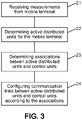
- Figure 3 illustrates a proposed method according to one or more embodiments.
- a fronthaul network of a wireless communication system may be managed through dynamic configuration/reconfiguration by a controller of the wireless communication system.
- the fronthaul network may comprise several distributed units and one or more central units, wherein each distributed unit of the several distributed units may be configured to provide, under the control of a central unit of the one or more central units, wireless communication of data between a mobile terminal and the fronthaul network.
- a fronthaul network dynamic configuration may be performed on the fronthaul network, which may comprise the receiving 21 measurements from the mobile terminal.
- the measurements received from the mobile terminal may comprise measurements related to a position or location of the mobile terminal, measurements related to a speed of the mobile terminal, and/or measurements related to a direction of movement of the mobile terminal.
- Information regarding a geo-location of the mobile terminal may be obtained through different methods, the results of which may be used alone or in combination to increase their accuracy.
- the mobile terminal may be equipped with a geo-positioning sensor (e.g., a Global Positioning System sensor, a Galileo sensor, or the like), and configured to transmit to the wireless communication system information indicating its geo-location.
- the wireless communication system may be configured to determine a position of the mobile terminal based on information received from the mobile terminal, for example based on the base stations of the fronthaul network with which the mobile terminal is in wireless communication, the geo-location of such base stations (e.g., of distributed units or remote radio heads thereof) being known.
- Information regarding a geo-location of the mobile terminal may be obtained through different methods, the results of which may be used alone or in combination to increase their accuracy.
- the mobile terminal may be equipped with a geo-positioning sensor (e.g., a Global Positioning System sensor, a Galileo sensor, or the like), and configured to transmit to the wireless communication system information indicating its speed.
- the wireless communication system may be configured to determine a speed of the mobile terminal based on information received from the mobile terminal, for example based on geo-location of the mobile terminal obtained at the wireless communication system.
- a direction of movement of the mobile terminal may also, depending on the embodiment, be determined and transmitted by the mobile terminal, or be determined by the system based on information regarding the mobile terminal obtained by the system, such as, for example, geo-positioning information.
- a trajectory of the mobile terminal may be predefined, and stored in a database of the wireless communication system, for example as a set of geolocations respectively associated with directions of movement. Such may typically be the case, for example for HST communication systems, where the system may be provided with a database where trains are identified in correspondence with trajectories, or for example for loT networks where machines (robots) are configured to be mobile according to predefined trajectories.
- a set of one or more active distributed units among the plurality of distributed units may then be obtained 22, based on the received measurements, for the mobile terminal. That is, the one or more active distributed units may be usable by the mobile terminal for radio communication with the fronthaul network.
- a distributed unit may be considered active upon the setting up or the configuration of one or more active associations with one or more CUs, that is, the DU may be configured for transmitting and/or receiving data packets to and/or from these one or more CUs in the fronthaul network.
- measurement DUs may be DUs with active radio but which are not associated to CUs of the fronthaul network.
- the received measurements comprise a location and a speed of the mobile terminal, and in which a trajectory of the mobile terminal is known to the system, future locations of the mobile terminal on such trajectory are determined, and active distributed units may be identified based on the determined future locations of the mobile terminal. That is, distributed units may be selected among the distributed units of the fronthaul network to anticipate their use for wireless data communication between the mobile terminal and the fronthaul network.
- the set of active distributed units determined for the fronthaul network configuration may be determined repeatedly as the mobile terminal moves along its trajectory (for example as the HST moves along its tracks). Determined sets of active distributed units may then be stored, in association with corresponding positions on the mobile terminal trajectory, for example in a database configured for storing data representing such information.
- a set of active distributed units may then be, depending on the embodiment, retrieved from the database based on a position of the mobile terminal on its trajectory, determined based on the position of the mobile terminal on its trajectory, or both, for purposes of comparing the set stored in the database with the determined set and possibly updating the set of active distributed units data stored in the database based on the comparison results.
- central units for controlling the identified active distributed units may then be determined. Said otherwise, associations between each of the active distributed units in the set of obtained distributed units and one or more respective central units of the one or more central units may be determined 23.
- the fronthaul network topology may allow selecting one or several of a plurality of central units to manage a distributed unit, so that one or several associations may be determined between the one or several central units that can be selected, and an active distributed unit of the obtained set of active distributed units for the mobile terminal. An association may also be determined between a single central unit and a plurality of active distributed units.
- the communication links between each of the active distributed units and their respective one or more central units may then be configured 24 according to the determined associations.
- this may entail activating respective communication links between the DUs and the CUs according to the determined associations, so that the fronthaul network may be reconfigured according to the determined associations.
- the activating a communication link between a DU and a CU may, depending on the interfaces used on such communication link, include activating such interfaces, setting up connections, setting up data paths according to the communication protocols used by the interfaces, etc.
- the configuration of the communication links between each of the active distributed units and their respective one or more central units may also entail, in some embodiments, the deactivating of some communication link as part of the reconfiguring of the fronthaul network.
- the fronthaul network dynamic configuration may further comprise the transmitting to the mobile terminal fronthaul network configuration information that comprises information indicating the set of one or more active distributed units.
- the mobile terminal may be informed by the system on active distributed units that are usable, and which have been selected by the system, for its wireless communication with the fronthaul network.
- the dynamic fronthaul network configuration or reconfiguration may be completely transparent to the mobile terminal, which may perform handovers between active distributed units as it moves along its trajectory in a transparent manner, that is, with no change as compared to its handover operations with respect to any fronthaul network.
- the dynamic reconfiguration of the fronthaul network may include the determining or obtaining (e.g., from a database storing relevant data) an updated set of active DUs based on the position of the mobile terminal, the determining or obtaining (e.g., from a database storing relevant data) of CUs to control the active DUs, and the configuration of the communication links between the selected CUs and active DUs.
- the fronthaul network dynamic configuration may further comprise the obtaining, based on the information indicating a positioning of the mobile terminal, on information indicating a speed of the mobile terminal, and information indicating a direction of movement of the mobile terminal, a set of one or more measurement distributed units among the plurality of distributed units, to be used by the mobile terminal for radio measurements on wireless links between the mobile terminal and the measurement distributed units.
- the mobile terminal may have a predetermined trajectory, so that information related to its direction of movement may be known (e.g., stored in a database storing its trajectory) for positions along its trajectory.
- the system may be configured to determine DUs with respect to which the mobile terminal may be able to perform measurements, based on the information indicating a positioning of the mobile terminal and information indicating a speed of the mobile terminal.
- the information related to its speed may be used to predict the mobile terminal's position P2 at time T2, where T2>T1.
- the mobile terminal may have a predetermined path along its trajectory, as for instance would be the case for trains having a predetermined path along their respective railway tracks, in particular HSTs.
- information related to the speed of the mobile terminal may also be predetermined, and stored in a database in association with respective positions of the mobile terminal along its trajectory, and may be obtained by being retrieved from the database when needed for the determination of the set of measurement DUs.
- the information related to the speed of the mobile terminal may be received from the terminal.
- the set of measurement DUs may have been previously determined, and stored in association with respective locations of the mobile terminal in a database configured for storing data representing sets of measurement DUs associated with respective locations of the mobile terminal.
- the set of measurement DUs that correspond to the current location of the mobile terminal may be obtained by being retrieved from the database.
- the set of measurement DUs may have been previously determined, and stored in association with respective locations of the mobile terminal and respective speeds of the mobile terminal in a database configured for storing data representing sets of measurement DUs associated with respective locations of the mobile terminal and respective speeds of the mobile terminal.
- the set of measurement DUs that correspond to the current location of the mobile terminal and to the current speed of the mobile terminal may be obtained by being retrieved from the database.
- the location and speed of the terminal may each be measured by the terminal and received therefrom, or determined by the system based on wireless communications with the terminal.
- the system may be configured to transmit to the mobile terminal information indicating the set of one or more measurement distributed units, for example comprised in the fronthaul network configuration information.
- the mobile terminal may be configured to, further to receiving such information indicating the set of one or more measurement distributed units, perform measurements on radio signals received from the measurement distributed units.
- the mobile terminal may further be configured to transmit to the controller measurement data resulting from the measurements performed with the measurement distributed units.
- the set of measurement distributed units may preferably include the set of active distributed units, as the mobile terminal may also be configured to perform measurements on radio signals exchanged with the active distributed units.
- the associations may be determined with an objective to increase a data communication throughput between the mobile terminal and the fronthaul network.
- the associations may be determined with an objective to increase a resiliency of the fronthaul network for data communications between the mobile terminal and the fronthaul network.
- the HST mobile terminal 14 may be configured to measure radio signals from a set of DUs, i.e. a measurement set 19, that is larger than the active DUs set 18.
- the measurements and additional network information such as the current position, current speed of the train, and/or radio parameters map of the propagation may be transmitted by the mobile terminal 14 to the switch controller 17, which may be configured to use such information to configure the CU/DU association matrix 16.
- the switch/association matrix 16 may be dynamically configured so as to provide seamless connectivity between the CUs and the DUs according to the mobility of the mobile terminal 14.
- the associations may be activated between the active DUs set 18 and a specific set of CUs as long as the mobile terminal is associated to the active DUs set 18, and deactivated upon the mobile terminal moving away from the active DUs set 18.
- the active DU set can be seen as a set of DUs that is sliding along the set of DUs deployed for the fronthaul network as the mobile terminal 14 moves along its trajectory (as the train 14a moves along its railway tracks).
- the switch/association matrix 16 may be configured/ reconfigured according to a fronthaul network reconfiguration update function that determines whether reconfiguration is to be performed based on reconfiguration parameters that include the speed of the mobile terminal 14 along its trajectory. For example, in some embodiments, the fronthaul configuration latency may be reduced when the speed of the HST is increased, and/or the fronthaul configuration latency may be increased for low speeds of the HST. The fronthaul configuration latency may be determined in some embodiments based on a lookup table in which predetermined configuration latencies may be respectively associated with HST speeds.
- the switch/association matrix 16 may be dynamically configured so as to provide connections between the CUs and the DUs that maximize the sum throughput offered to the active DU set. This optimization may in some embodiments take into account the throughput limit on the different fronthaul associations, which may occur for example when congestion is detected in the fronthaul or when the association matrix is formed of different heterogeneous wired connections.
- the switch/association matrix 16 may be dynamically configured so as to increase and/or adapt the fronthaul redundancy in order to protect the associations between the CUs and DUs from congestions that are detected or may occur during the mobility of the mobile terminal 14.
- the switch controller 17 may be configured to set radio parameters of the active DUs in order to configure the active DUs area into a single frequency network (SFN), so as to improve the throughput of data received from multiple active DUs 13c, 13e at the mobile terminal 14.
- the switch controller 17 may further be configured to also configure connections between the CUs and the DUs contributing to the SFN area, and setup multipoint transmissions between the DUs and the mobile terminal 14.
- the switch controller 17 may be configured to determine based on the measurements of the HST, a set of active DUs, and modify the radio parameters of the set of active DUs in order to setup a single frequency network configuration.
- the switch controller 17 may be configured to setup the associations between the CUs and the active DUs as well as between the CUs in order to coordinate the transmissions between the CUs and the active DUs of the single frequency network.
- the mobile terminal 14 may receive from the network signaling data comprising information regarding combinations of data packets received from the different active DUs of the SFN network in order to start coordinated multipoint transmission.
- the coordinated multipoint transmission allows the mobile terminal to receive coordinated and non-interfering transmissions from multiple DUs in order to increase the throughput received at the high speed train.
- the switch controller 17 may be configured to determine the active DU set 18, the measurement DU set 19, and the CU set, based on received measurements performed by the mobile terminal 14.
- the measurement DU set 19 may be used to select the DUs that will be used for the future reconfiguration of the switch/association matrix 16.
- the CU set may advantageously be determined for load balancing among the CUs, for example as the set of CUs that includes the less loaded CUs among the CUs that may contribute to the future fronthaul reconfiguration.
- the active DU set 18, the measurement DU set 19, and/or the CU set may be determined based on the position of the mobile terminal 14.
- the active DU set 18, the measurement DU set 19, and/or the CU set may further be determined based on the speed of the of the mobile terminal 14.
- the size of the measurement DU 19 may be increased in order to anticipate a dynamic fronthaul configuration if the speed of the mobile terminal 14 is higher than a predetermined threshold, which may for example be around 150km/h.
- the active DU set 18 may be determined as the set of DUs that includes DUs to which a mobile terminal 14 is connected along the railroad side.
- the active DU set 18, the measurement DU set 19, and/or the CU set may be determined based on the traffic on the railroad. For example, if there are N mobile terminal respectively corresponding to N trains currently active in the railroad, the active DU set 18 and measurement DU set 19 and/or the CU set may be determined jointly for the N different mobile terminals.
- the active DU set 18, the measurement DU set 19, and/or the CU set may be determined based on a measured railroad interference profile, i.e. the power of the interference measured at the mobile terminal, and/or the interference between the active DUs that are associated with different mobile terminals.
- the active DUs may thus be determined as the DUs that are the most interfering over the mobile terminals of the deployment.
- the active DUs may be the DUs that are interfering over a high number of HST in the scenario.
- the switch controller 17 may be configured to dynamically configure/reconfigure the switch/association matrix 16 in order to provide connectivity and improve the throughput offered to the active DUs, based on the position of the mobile terminal 14.
- the configuring of the switch/association matrix 16 may include setting logical fronthaul connections among the less loaded CUs and the DUs that are obtained from the determination of the set of measurement DUs (that is, the measurement DUs), and that are best received by the mobile terminal 14 (for example that are received by the mobile terminal 14 with a signal to noise (SNR) ratio above a predetermined threshold, which may be dynamically updated or fixed, depending on the embodiment).
- SNR signal to noise
- the configuring of the switch/association matrix 16 may include setting logical fronthaul connections among any of the available CUs and the DUs of the set of measurement DUs, and that are best received by the mobile terminal 14 (for example that are received by the mobile terminal 14 with a SNR above a predetermined threshold, which may be dynamically updated or fixed, depending on the embodiment). This advantageously allows anticipating the handover of the mobile terminal 14 by preparing the connections between the CUs and the DUs of the set of measurement DUs, thereby improving the handover latency of the switch/association matrix 16 reconfiguration.
- the configuring of the switch/association matrix 16 may include determining the fronthaul connection capacities between the available CUs and the DUs of the set of measurement DUs, and that are best received by the mobile terminal 14 (for example that are received by the mobile terminal 14 with a SNR above a predetermined threshold, which may be dynamically updated or fixed, depending on the embodiment).
- the switch controller 17 may be configured to determine, based on the capacities, a subset of associations between the CU and the DUs that maximizes the sum of the throughput that is offered to the DUs from the measurement set, i.e.
- the obtained subset of associations may determine both the CUs and the active DUs.
- the switch/association matrix 16 redundancy may be configured/reconfigured in order to protect the fronthaul network against CU, DU and/or communication links between CUs and DUs failures.
- the switch/association matrix 16 redundancy may be updated based on a CU degree criterion defined for a CU of the switch/association matrix 16 as the number of DUs in the switch/association matrix 16 connected to the CU.
- the configuring of the switch/association matrix 16 may in such embodiments include increasing a CU degree if failures of DUs connected to the CU are expected/anticipated in the switch/association matrix 16. For example, in case of failure of a DU connected to the CU, a data packet of the CU intended for the failing DU may be retransmitted with lower latency and/or broadcasted to the active DUs determined for the mobile terminal 14.
- the switch/association matrix 16 redundancy may be updated based on a DU degree criterion defined for a DU of the switch/association matrix 16 as the number of CUs connected to the DU.
- the configuring of the switch/association matrix 16 may in such embodiments include increasing a DU degree if failures of a CU connected to the DU are expected/anticipated in the switch/association matrix 16. For example, in case of failure of a CU that is connected to multiple DUs, an uplink packet of the DU may be retransmitted to another CU in the CU pool of the DU, where the CU pool of the DU is the set of CUs that the DU is connected to, further to the reconfiguration of the switch/association matrix 16.
- the switch/association matrix 16 redundancy may be updated based on an average number of paths from any CU in a determined set of CUs to any DU in a set of DUs that are connected to the CUs of the set of CUs with latency lower than a predetermined threshold. These paths are considering the CU-DU associations as well as the connections between different CUs in the CU set.
- the configuring of the switch/association matrix 16 may in such embodiments include increasing this average number of paths by establishing additional CU/DU associations and/or CU/CU connections with controllable latency if a number of association failures between the CUs and DUs and between the CUs are detected in the switch/association matrix.
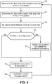
- Figure 4 is a flow diagram that illustrates a method for configuring a switch/association matrix according to one or more embodiments.
- Figure 5 illustrates the method for configuring a switch/association matrix according to one or more embodiments.
- the fronthaul network dynamic configuration may be performed at iterations of a fronthaul network dynamic configuration loop, an iteration of the loop being executed for each portion of the railroad model.
- the switch controller 17 may be configured to, upon detecting that the train 14a enters the k th portion Portion_k, execute a k th iteration of the fronthaul network dynamic configuration loop.
- the kth iteration of the loop may include the determination 30 of a measurement DU set 19, the determination 31 of the active DU set 18 and of CUs for the portion Portion_k + 1 and in some embodiments the determination of additional DUs that will be added in order to absorb additional delay of the fronthaul reconfiguration (not shown on the figure), possibly based upon measurement information received by the controller 17 from the mobile terminal 14. Indeed, in some embodiments, the mobile terminal may perform measurements related to the portion ( Portion_k + 1) following the one in which it is currently located ( Portion_k ), and transmit measurement information generated from these measurements to the controller 17.
- the measurement information received from the mobile terminal 14 may be used by the controller 17 for the determination 30 of a measurement DU set 19, the determination 31 of the active DU set 18 and of CUs for the portion rtion_k + 1 , the active DU set 18 being determined in some embodiments based on the determined measurement DU set 19 (for example as a subset of the measurement DU set 19), and/or the determination of additional DUs, as the case may be.
- the k th iteration of the loop may then potentially include the updating 32 of the associations between the CUs and the DUs in the switch/association matrix 16 in order to increase the throughput offered by the switch/association matrix 16 to the DUs in the portion Portion_k, which may or may not lead to the reconfiguration of the fronthaul network according to the updated associations.
- a determination 34 as to whether the redundancy of the portion Portion_k may also be performed, and the fronthaul network may be reconfigured accordingly.
- the k th iteration of the loop is completed upon configuring 35 the fronthaul network corresponding to the portion Portion_k according to updated associations, as the case may be, after which the loop index k is incremented 36, so as to execute a following loop iteration upon entering in the following portion ( Portion_k + 1) according to the railroad model.
- the railroad may be modelled as a single portion corresponding to the entire railroad.
- the switch controller 17 may be configured to determine the active and measurement DU sets for the high speed trains that are present on the railroad as well as the corresponding CUs. The switch controller 17 may then be further configured to update the association between the CUs and the DUs, and/or finally the redundancy of the fronthaul network.
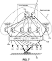
- Figure 6 illustrates a centralized switch controller feature according to one or more embodiments.
- the railroad may be split into several zones, each zone being controlled by a zone controller.
- Figure 6 shows one zone 40 of the railroad, which is controlled by a zone controller 15.
- the zone controller 15 may comprise LTE core network nodes/servers 15a, such as a node configured as a mobility management entity (MME) and/or a node configured as a serving gateway (S-GW), and may be configured to set the speed profile of the train 14a in the zone 40, and each zone may include K tracks, where each track is associated to a corresponding switch/association matrix 16a, 16b.
- a switch controller configured for controlling the switch/association matrices 16a-16b in the zone may be co-located with the zone controller 15 or, as illustrated in Fig.
- a switch controller feature 17 may be implemented in the zone controller 15.
- a zone controller 15 implementing a switch controller feature 17 may be configured to perform the embodiments of the proposed method with respect to the switch controller feature 17 according to the present subject disclosure.
- a zone controller 15 implementing a switch controller feature 17 may, in some embodiments, be configured to receive measurements (e.g., related to a positioning of the mobile terminal 14, a positioning of the train 14a, a speed of the mobile terminal 14, a speed of the train 14a, etc.) from the train 14a, and/or to receive network state information from the fronthaul network (e.g., fronthaul congestion indicator(s)).
- measurements e.g., related to a positioning of the mobile terminal 14, a positioning of the train 14a, a speed of the mobile terminal 14, a speed of the train 14a, etc.
- network state information e.g., fronthaul congestion indicator(s)
- the zone controller 15 implementing a switch controller feature 17 may further be configured to use the received measurements and/or the received network state information to configure one or more of the switch/association matrices 16a, 16b associated with the zone 40.
- the fronthaul network reconfiguration may comprise determining CU-DU associations in one or more of the switch/association matrices 16a, 16b that improve the throughput offered to sets of active DUs respectively corresponding to trains distributed on the railroad.
- a fronthaul network reconfiguration may also be performed in some embodiments to modify the redundancy of the CU-DU associations in the switch/association matrices 16a, 16b in order to protect them from CU, DU and/or association failures.
- the switch controller 17 may be configured to configure each active DU set into a single frequency network (SFN) area.
- the active DUs may be configured in the SFN network area setting by the switch controller to transmit data to the HST using coordinated multipoint transmission.
- the embodiments that use a centralized controller may advantageously be backward compatible with LTE networks:
- the switch controller can indeed be located in a LTE MME node and the CU/switch controller architecture can be based on the LTE S1 Application Protocol (S1AP) specified in the 3GPP technical specification TS 36.413.
- S1AP LTE S1 Application Protocol
- Another advantage of embodiments that use a centralized controller is the level of performance due to the switch controller receiving all the above-described network state information from the nodes of the switch/association matrix/ces of the zone, while the controller may be configured to configure/reconfigure the fronthaul network for all the switches of the railroad.
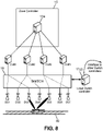
- the switch controller feature 17 may be split between a part implemented in the zone controller 15 and one or more local switch controllers 17b, 17c.
- the zone controller part 17a of the switch controller 17 may be configured to update the redundancy of the fronthaul network in the zone 40 while the local switch controller part 17b, 17c may be configured to update the CU-DU associations in the one or more switch/association matrices 16a, 16b, such that the throughput of communication links between the fronthaul network and the train is improved.
- the semi-centralized switch controller embodiments may advantageously be used for their increased flexibility and reduced complexity as compared to the centralized switch controller embodiments.
- Semi-centralized switch controller embodiments provide an increased resistance to failures in the zone controller node.
- the switch controller 17 may be split into several local switch controllers 17(z) configured to update the associations of a switch/association matrix to improve the throughput of data communications with mobile terminals onboard the train and/or improve the redundancy of the fronthaul network in a respective zone 40.
- the local switch controllers 17(z) may not be co- located with or implemented in the zone controller 15, and may be for example implemented in a DU of the zone or next to a local gateway (L-GW) that is closer to the DUs than the zone controller.
- L-GW local gateway
- the distributed switch controller embodiments may advantageously be used for their increased adaptability and lower complexity when compared to other embodiments.
- the distributed switch controller embodiments advantageously involve less signaling overhead with respect to semi-centralized switch controller embodiments, as there is no need to coordinate between multiple distributed local controllers and a central switch controller, however possibly at the expense of an increased inter-local-switch-controllers signaling.
- an apparatus configured to function as a network node in a computer network, comprising a processor and a memory operatively coupled to the processor, wherein the processor is configured for performing the above method for managing a fronthaul network, is also proposed.
- Fig. 9 illustrates an exemplary network node 101 configured to implement a switch controller function in accordance with embodiments of the present subject disclosure.
- the network node 101 includes a control engine 102, a network management engine 103, a data communication engine 104, and memory 105.
- the network management engine 103 is configured to perform various aspects of embodiments of the proposed method for network management. For example, as described above, in embodiments in which the CUs are configured to generate in the downlink Ethernet packets based on CPRI signals to be transmitted to one or more DUs, each Ethernet packet comprising a MAC address of the CU and a MAC address of a destination DU, the network management engine 103 may be configured to determine which DU is to be activated, and to control the updating of destination MAC addresses in the generated Ethernet packets accordingly. In other embodiments, the network management engine 103 may be configured to control the updating of source MAC addresses in the generated Ethernet packets, so as to activate a data communication link or path between a DU and a different CU corresponding to the updated source MAC address.
- the network management engine 103 may be configured to be operatively connected to a database server (not shown on the figure) which, depending on the implementation, may be co-located with the network management node (101) or an element thereof.
- the database server may be a NoSQL database, for example implemented using the Cassandra No SQL database technology, and may be configured to store data representing a switch/association matrix according to the present subject disclosure.
- the database server may be configured to store data representing fronthaul configurations, possibly associated with time information and/or location information.
- the database server may be configured to store a set of fronthaul configurations, each fronthaul configuration comprising data representing a switch/association matrix, and each fronthaul association being associated with time information and/or HST location information, so that the fronthaul network may be configured based on a location of a HST on its railway tracks, and/or based on timing information of a HST traveling on its railway tracks.
- the database server may further be configured to store a current fronthaul network configuration comprising data representing a switch/association matrix currently used to configure the fronthaul network.
- the data communication engine 104 is configured to receive and transmit signaling data from and to a switch/association matrix to which the node 101 is communicatively connected through the data communication engine 104.
- the data communication engine 104 and the network management engine 103 operate in a coordinated manner for purposes of determining fronthaul network configurations according to embodiments of the present subject disclosure.
- the control engine 102 includes one or more computers, each including one or more processors, which each may be any suitable microprocessor, microcontroller, Field Programmable Gate Arrays (FPGA), Application Specific Integrated Circuits (ASIC), Digital Signal Processing chip, and/or state machine, or a combination thereof. According to various embodiments, one or more of the computers can be configured as a multi-processor computer having multiple processors for providing parallel computing.
- the control engine 102 may also comprise, or may be in communication with, computer storage media, such as, without limitation, the memory 105, capable of storing computer program instructions or software code that, when executed by the processor, cause the processor to perform the elements described herein.
- the memory 105 may be any type of data storage computer storage medium, capable of storing a data structure representing a computer network to which the network node 101 belongs, coupled to the control engine 102 and operable with the data communication engine 104 and the network management engine 103 to facilitate management and processing of data stored in association therewith.
- the network node 101 shown and described with reference to Fig. 9 is provided by way of example only. Numerous other architectures, operating environments, and configurations are possible. Other embodiments of the node may include fewer or greater number of components, and may incorporate some or all of the functionality described with respect to the network node components shown in Fig. 9 . Accordingly, although the control engine 102, network management engine 103, data communication engine 104, and memory 105 are illustrated as part of the network node 101, no restrictions are placed on the location and control of components 102 - 105. In particular, in other embodiments, components 102 - 105 may be part of different entities or computing systems, for example as described above with respect of embodiments (centralized, semi-distributed, distributed) of the switch controller.
- the methods and apparatuses according to embodiments of the present subject disclosure offer the following advantages, in particular with respect to conventional train communication systems:
- the advantages of the invention with respect to state of the art in train communication system are given as the following:
- the present subject disclosure proposes an adaptive architecture that improves the flexibility of the fronthaul network deployment. For example, a single deployment is able to cope with a variety of traffic intensities, through the use in some embodiments of a reconfigurable switch/association matrix and a switch controller.
- Conventional systems propose essentially static and non-reconfigurable switches.
- the present subject disclosure further proposes means to improve the throughput offered to mobile terminals onboard a train, in particular a HST train, by adapting the fronthaul network configuration and topology to the position and speed of the train.
- the adaptation of the fronthaul network may be performed in some embodiments by selecting associations among central units CUs and railroad side distributed units that maximize the sum of the throughput carried out to the active DUs.
- the present subject disclosure further proposes to improve the resilience of the overall network in some embodiments by setting and updating the redundancy of the fronthaul network based on the propagation conditions in the railroad and/or the speed and positions of the train.
- the present subject disclosure further proposes techniques to reduce the latency of the fronthaul and fronthaul reconfiguration by means in some embodiments of selecting the fastest associations from the available CU-DU associations and by using mobile edge computing. More specifically, in some embodiments the switch controller may be located close to the switch/association matrix in order to increase the reactivity of the proposed method.
- the present subject disclosure may also advantageously enable energy saving, since in some embodiments techniques are proposed for the reduction of the number of central units (CUs) involved in the CU-DU associations, thus saving also computation power for a given set of active/measurement DUs.
- CUs central units
- Information and signals described herein can be represented using any of a variety of different technologies and techniques.
- data, instructions, commands, information, signals, bits, symbols, and chips can be represented by voltages, currents, electromagnetic waves, magnetic fields or particles, optical fields or particles, or any combination thereof.
Landscapes
- Engineering & Computer Science (AREA)
- Computer Networks & Wireless Communication (AREA)
- Signal Processing (AREA)
- Business, Economics & Management (AREA)
- General Business, Economics & Management (AREA)
- Quality & Reliability (AREA)
- Accounting & Taxation (AREA)
- Mobile Radio Communication Systems (AREA)
Claims (13)
- Verfahren zum Verwalten eines Fronthaul-Netzwerks in einem drahtlosen Kommunikationssystem, wobei das Fronthaul-Netzwerk mehrere verteilte Einheiten (13a - 13g) und eine oder mehrere zentrale Einheiten (12a - 12d) umfasst, wobei jede verteilte Einheit der mehreren verteilten Einheiten (13a-13g) dazu eingerichtet ist, unter der Steuerung einer zentralen Einheit der einen oder der mehreren zentralen Einheiten (12a - 12d) eine drahtlose Kommunikation von Daten zwischen einem mobilen Endgerät (14) und dem Fronthaul-Netzwerk bereitzustellen, wobei das Verfahren umfasst: Durchführen einer dynamischen Konfiguration des Fronthaul-Netzwerks an dem Fronthaul-Netzwerk, wobei die dynamische Konfiguration des Fronthaul-Netzwerks in einer Steuereinrichtung (17) des drahtlosen Kommunikationssystems umfasst:- Erhalten (21) von Informationen, welche eine Positionierung des mobilen Endgeräts (14) angeben, wobei die Informationen durch ein Empfangen von Messungen von dem mobilen Endgerät erhalten werden, welche Messungen umfassen, die sich auf einen Standort des mobilen Endgeräts, eine Geschwindigkeit des mobilen Endgeräts und eine Bewegungsrichtung des mobilen Endgeräts beziehen;- Bestimmen zukünftiger Standorte des mobilen Endgeräts auf Grundlage der empfangenen Messungen;- Erhalten (22), auf Grundlage der Informationen, welche eine Positionierung des mobilen Endgeräts (14) angeben, eines Satzes einer oder mehrerer aktiver verteilter Einheiten unter der Mehrzahl verteilter Einheiten (13a - 13g), wobei die eine oder die mehreren aktiven verteilten Einheiten durch das mobile Endgerät (14) für eine drahtlose Kommunikation mit dem Fronthaul-Netzwerk verwendbar sind und wobei die eine oder die mehreren aktiven verteilten Einheiten auf Grundlage der bestimmten zukünftigen Standorte des mobilen Endgeräts unter der Mehrzahl verteilter Einheiten (13a - 13g) identifiziert werden;- Bestimmen (23) erster Zuordnungen zwischen jeder der aktiven verteilten Einheiten und einer oder mehrerer erster jeweiliger zentraler Einheiten der einen oder der mehreren zentralen Einheiten; und- Konfigurieren (24) von Kommunikationsverbindungen zwischen jeder der aktiven verteilten Einheiten und deren ersten jeweiligen einen oder mehreren zentralen Einheiten gemäß den bestimmten ersten Zuordnungen.
- Verfahren nach einem der vorhergehenden Ansprüche, wobei die dynamische Konfiguration des Fronthaul-Netzwerks ferner umfasst: Übertragen von Konfigurationsinformationen des Fronthaul-Netzwerks an das mobile Endgerät, wobei die Konfigurationsinformationen des Fronthaul-Netzwerks Informationen umfassen, welche den Satz einer oder mehrerer aktiver verteilter Einheiten angeben.
- Verfahren nach Anspruch 1, wobei das Konfigurieren der Verbindungen zwischen jeder der aktiven verteilten Einheiten und deren jeweiligen einen oder mehreren zentralen Einheiten ein Aktivieren und/oder Deaktivieren von Verbindungen in einer Matrix verfügbarer Verbindungen unter den mehreren verteilten Einheiten und einer oder mehreren zentralen Einheiten des Fronthaul-Netzwerks umfasst.
- Verfahren nach einem der vorhergehenden Ansprüche, wobei das Bestimmen der Zuordnungen ein Bestimmen von Zuordnungen umfasst, welche einen Datenkommunikationsdurchsatz zwischen dem mobilen Endgerät und dem Fronthaul-Netzwerk erhöhen.
- Verfahren nach einem der vorhergehenden Ansprüche, wobei die dynamische Konfiguration des Fronthaul-Netzwerks ferner umfasst: Konfigurieren von Funkparametern der aktiven verteilten Einheiten, um die aktiven verteilten Einheiten als ein Single Frequency Network zu konfigurieren.
- Verfahren nach einem der vorhergehenden Ansprüche, wobei das Bestimmen der Zuordnungen ein Bestimmen von Zuordnungen umfasst, welche eine Fronthaul-Netzwerk-Stabilität für Datenkommunikationen zwischen dem mobilen Endgerät und dem Fronthaul-Netzwerk erhöhen und/oder anpassen.
- Verfahren nach einem der vorhergehenden Ansprüche, wobei die dynamische Konfiguration des Fronthaul-Netzwerks iterativ in einer dynamischen Konfigurationsschleife des Fronthaul-Netzwerks durchgeführt wird.
- Verfahren nach Anspruch 7, wobei eine Iteration der dynamischen Konfigurationsschleife des Fronthaul-Netzwerks im Wesentlichen periodisch ausgeführt wird.
- Verfahren nach Anspruch 7, wobei eine Trajektorie des mobilen Endgeräts in Abschnitte unterteilt ist und wobei eine Iteration der dynamischen Konfigurationsschleife des Fronthaul-Netzwerks für jeden Abschnitt der Trajektorie ausgeführt wird.
- Verfahren nach einem der Ansprüche 2 und 3 - 9, wenn sie von Anspruch 2 abhängig sind, wobei die dynamische Konfiguration des Fronthaul-Netzwerks ferner umfasst: Erhalten, auf Grundlage von Informationen, welche eine Positionierung des mobilen Endgeräts angeben, von Informationen, welche eine Geschwindigkeit des mobilen Endgeräts angeben, und Informationen, welche eine Bewegungsrichtung des mobilen Endgeräts angeben, eines Satzes einer oder mehrerer verteilter Messeinheiten unter der Mehrzahl verteilter Einheiten, welche durch das mobile Endgerät für Funkmessungen an drahtlosen Verbindungen zwischen dem mobilen Endgerät und den verteilten Messeinheiten zu verwenden sind, wobei die Konfigurationsinformationen des Fronthaul-Netzwerks Informationen umfassen, welche den Satz einer oder mehrerer verteilter Messeinheiten angeben.
- Verfahren nach Anspruch 10, wobei die dynamische Konfiguration des Fronthaul-Netzwerks ferner umfasst: Bestimmen zweiter Zuordnungen zwischen wenigstens einer der verteilten Messeinheiten und einer oder mehrerer zweiten jeweiligen zentralen Einheiten der einen oder der mehreren zentralen Einheiten und Konfigurieren von Kommunikationsverbindungen zwischen jeder der wenigstens einen verteilten Messeinheit und deren zweiten jeweiligen einen oder mehreren zentralen Einheiten gemäß den bestimmten zweiten Zuordnungen.
- Vorrichtung (101), wobei die Vorrichtung (101) einen Prozessor (102), einen Speicher (105), welcher betriebsmäßig mit dem Prozessor (102) gekoppelt ist, und Netzwerkschnittstellen umfasst, um in einem drahtlosen Kommunikationssystem zu kommunizieren, wobei die Vorrichtung (101) dazu eingerichtet ist, ein Verfahren nach einem der Ansprüche 1 bis 11 durchzuführen.
- Computerprogrammprodukt, umfassend Computerprogrammcode, welcher greifbar in einem computerlesbaren Medium verkörpert ist, wobei der Computerprogrammcode Anweisungen umfasst, um, wenn sie einem Computersystem bereitgestellt werden und darauf ausgeführt werden, den Computer zu veranlassen, ein Verfahren nach einem der Ansprüche 1 bis 11 durchzuführen.
Priority Applications (5)
| Application Number | Priority Date | Filing Date | Title |
|---|---|---|---|
| EP18306140.7A EP3618518B1 (de) | 2018-08-28 | 2018-08-28 | Verfahren zur verwaltung eines drahtlosnetzwerks und netzwerkknoten zur implementierung davon |
| PCT/JP2019/034032 WO2020045603A1 (en) | 2018-08-28 | 2019-08-23 | Method for managing fronthaul network, apparatus, computer program product, and data set |
| US17/252,916 US11490274B2 (en) | 2018-08-28 | 2019-08-23 | Method for managing fronthaul network, apparatus, computer program product, and data set |
| JP2020568350A JP7142726B2 (ja) | 2018-08-28 | 2019-08-23 | フロントホールネットワークを管理する方法、装置、コンピュータプログラム製品、及びデータセット |
| CN201980055091.XA CN112586048B (zh) | 2018-08-28 | 2019-08-23 | 管理前传网络的方法、设备、计算机程序产品和数据集 |
Applications Claiming Priority (1)
| Application Number | Priority Date | Filing Date | Title |
|---|---|---|---|
| EP18306140.7A EP3618518B1 (de) | 2018-08-28 | 2018-08-28 | Verfahren zur verwaltung eines drahtlosnetzwerks und netzwerkknoten zur implementierung davon |
Publications (2)
| Publication Number | Publication Date |
|---|---|
| EP3618518A1 EP3618518A1 (de) | 2020-03-04 |
| EP3618518B1 true EP3618518B1 (de) | 2022-11-30 |
Family
ID=63491545
Family Applications (1)
| Application Number | Title | Priority Date | Filing Date |
|---|---|---|---|
| EP18306140.7A Active EP3618518B1 (de) | 2018-08-28 | 2018-08-28 | Verfahren zur verwaltung eines drahtlosnetzwerks und netzwerkknoten zur implementierung davon |
Country Status (5)
| Country | Link |
|---|---|
| US (1) | US11490274B2 (de) |
| EP (1) | EP3618518B1 (de) |
| JP (1) | JP7142726B2 (de) |
| CN (1) | CN112586048B (de) |
| WO (1) | WO2020045603A1 (de) |
Families Citing this family (21)
| Publication number | Priority date | Publication date | Assignee | Title |
|---|---|---|---|---|
| EP3836621B1 (de) * | 2019-12-13 | 2023-10-18 | Fluidmesh Networks S.r.l. | Keyhole-verwaltung in der drahtlosenfunkkommunikation |
| JP7576401B2 (ja) * | 2020-03-27 | 2024-10-31 | 株式会社Nttドコモ | 無線通信システム |
| CN111901764A (zh) * | 2020-04-24 | 2020-11-06 | 中兴通讯股份有限公司 | 广播/组播业务的管理方法、装置、电子设备和存储介质 |
| CN113301092B (zh) * | 2020-07-31 | 2022-04-12 | 阿里巴巴集团控股有限公司 | 网络重连方法、设备、系统及存储介质 |
| US11431422B2 (en) * | 2020-11-05 | 2022-08-30 | Electronics And Telecommunications Research Institute | Calibration method for cooperative transmission of cell-free wireless network, and apparatus therefor |
| US11582642B2 (en) * | 2020-11-16 | 2023-02-14 | At&T Intellectual Property I, L.P. | Scaling network capability using baseband unit pooling in fifth generation networks and beyond |
| US11540330B2 (en) | 2020-11-25 | 2022-12-27 | At&T Intellectual Property I, L.P. | Allocation of baseband unit resources in fifth generation networks and beyond |
| CN113009901A (zh) * | 2021-02-08 | 2021-06-22 | 中车青岛四方机车车辆股份有限公司 | 车载物联网的架构、处理方法、处理装置和列车 |
| US11576069B2 (en) | 2021-02-17 | 2023-02-07 | Qualcomm Incorporated | Cell measurement and reporting for mobility in distributed wireless communications systems |
| CN115278865A (zh) * | 2021-04-30 | 2022-11-01 | 北京三星通信技术研究有限公司 | 定位配置方法和电子设备 |
| US20240196481A1 (en) * | 2021-05-08 | 2024-06-13 | Qualcomm Incorporated | System information block and paging transmission priority for sidelink relaying |
| WO2023084760A1 (ja) * | 2021-11-12 | 2023-05-19 | 株式会社Nttドコモ | ネットワークノード、通信方法及び通信システム |
| US12082106B2 (en) | 2022-02-25 | 2024-09-03 | At&T Intellectual Property I, L.P. | Sharing of baseband units in fifth generation networks and beyond |
| US12034603B2 (en) | 2022-03-04 | 2024-07-09 | AT&T Intellect al P Property I, L.P. | Pooling of baseband units in fifth generation networks and beyond |
| US11877163B2 (en) | 2022-03-25 | 2024-01-16 | Dish Wireless L.L.C. | Systems and methods for operating radio access networks with high service availability |
| US11836480B2 (en) * | 2022-03-25 | 2023-12-05 | Dish Wireless L.L.C. | Systems and methods for reducing service downtime during software upgrades |
| US12177871B2 (en) | 2022-06-28 | 2024-12-24 | At&T Intellectual Property I, L.P. | Baseband unit pooling using shared scheduler |
| US12513092B2 (en) | 2022-08-30 | 2025-12-30 | At&T Intellectual Property I, L.P. | Uninterrupted transfer of carriers between baseband unit server resources |
| US12382383B2 (en) * | 2022-11-08 | 2025-08-05 | Verizon Patent And Licensing Inc. | Systems and methods for dynamic edge computing device assignment and reassignment |
| WO2024145864A1 (zh) * | 2023-01-05 | 2024-07-11 | 华为技术有限公司 | 数据处理的方法与通信装置 |
| US20250344074A1 (en) * | 2024-05-06 | 2025-11-06 | AT&T Communications Services India Private Limited | Configuring a spectrum channel between a centralized unit and a distributed unit of a fronthaul optical network |
Family Cites Families (18)
| Publication number | Priority date | Publication date | Assignee | Title |
|---|---|---|---|---|
| EP1838122A1 (de) * | 2006-03-20 | 2007-09-26 | Mitsubishi Electric Information Technology Centre Europe B.V. | Verfahren und Vorrichtungen zur Bestimmung einer Lokalisierungszone eines zellularen Kommunikationsnetzes |
| WO2013187743A1 (ko) * | 2012-06-15 | 2013-12-19 | 엘지전자 주식회사 | 고정된 경로를 이동하는 고속 이동체를 위한 무선 통신 시스템 |
| GB201211568D0 (en) * | 2012-06-29 | 2012-08-15 | Microsoft Corp | Determining network availability based on geographical location |
| GB201211580D0 (en) * | 2012-06-29 | 2012-08-15 | Microsoft Corp | Determining suitablity of an access network |
| WO2015044871A1 (en) * | 2013-09-24 | 2015-04-02 | Andrew Wireless Systems Gmbh | Distributed processing in a centralized radio access network |
| WO2015051856A1 (en) * | 2013-10-11 | 2015-04-16 | Xieon Networks S.À.R.L. | Centralized data path establishment augmented with distributed control messaging |
| EP3167578B1 (de) * | 2014-07-11 | 2018-12-12 | Telefonaktiebolaget LM Ericsson (publ) | Optisches transportnetzwerk |
| EP3219158B1 (de) * | 2014-11-10 | 2023-05-03 | Telefonaktiebolaget LM Ericsson (publ) | Steuerungsserver mit zentralisiertem standort |
| WO2016145371A2 (en) * | 2015-03-11 | 2016-09-15 | Phluido, Inc. | Distributed radio access network with adaptive fronthaul |
| CN108370525A (zh) * | 2015-10-01 | 2018-08-03 | 瑞典爱立信有限公司 | 控制服务于交通运输系统的无线电网络的操作 |
| WO2017070635A1 (en) * | 2015-10-22 | 2017-04-27 | Phluido, Inc. | Virtualization and orchestration of a radio access network |
| WO2017147076A1 (en) * | 2016-02-22 | 2017-08-31 | Idac Holdings, Inc. | Methods, apparatuses and systems directed to common transport of backhaul and fronthaul traffic |
| US20170289854A1 (en) * | 2016-04-01 | 2017-10-05 | Industrial Technology Research Institute | Handover method used by network controller of transport network and network controller using the same |
| US10178702B2 (en) * | 2016-06-10 | 2019-01-08 | Futurewei Technologies, Inc. | System and method for cell switching |
| KR102100491B1 (ko) * | 2016-07-13 | 2020-04-14 | 주식회사 케이티 | 프론트홀 인터페이스를 이용한 중앙 유닛 구성 방법 및 그 장치 |
| US10499293B2 (en) | 2016-08-15 | 2019-12-03 | Qualcomm Incorporated | Handover in high speed networks |
| US10531336B2 (en) * | 2017-02-26 | 2020-01-07 | Mariana Goldhamer | Link control in centralized deployments |
| US10568004B2 (en) * | 2017-03-23 | 2020-02-18 | Futurewei Technologies, Inc. | Layer 2 (L2) mobility for new radio (NR) networks |
-
2018
- 2018-08-28 EP EP18306140.7A patent/EP3618518B1/de active Active
-
2019
- 2019-08-23 WO PCT/JP2019/034032 patent/WO2020045603A1/en not_active Ceased
- 2019-08-23 JP JP2020568350A patent/JP7142726B2/ja active Active
- 2019-08-23 US US17/252,916 patent/US11490274B2/en active Active
- 2019-08-23 CN CN201980055091.XA patent/CN112586048B/zh active Active
Also Published As
| Publication number | Publication date |
|---|---|
| JP7142726B2 (ja) | 2022-09-27 |
| US11490274B2 (en) | 2022-11-01 |
| EP3618518A1 (de) | 2020-03-04 |
| JP2021526758A (ja) | 2021-10-07 |
| CN112586048A (zh) | 2021-03-30 |
| CN112586048B (zh) | 2024-04-16 |
| WO2020045603A1 (en) | 2020-03-05 |
| US20210266764A1 (en) | 2021-08-26 |
Similar Documents
| Publication | Publication Date | Title |
|---|---|---|
| US11490274B2 (en) | Method for managing fronthaul network, apparatus, computer program product, and data set | |
| JP7507821B2 (ja) | 通信システム、セントラルユニット、およびユーザ装置 | |
| CN111066292B (zh) | 新空口网络的二层移动 | |
| US9578671B2 (en) | Establishing multiple connections between a user equipment and wireless access network nodes | |
| EP2508026B1 (de) | Übergabe von weitergeleiteten verbindungen in einer mobilen umgebung | |
| EP2914035B1 (de) | Basisstationsweiterreichungsverfahren und -system für ein kommunikationssystem | |
| US11722912B2 (en) | Radio link failure handling in an integrated access backhaul network | |
| KR20140009552A (ko) | 무선 통신 시스템에서의 상향링크 무선 주파수 신호 수신 방법, 그의 마스터 유닛 및 슬레이브 유닛 | |
| US11711733B2 (en) | Enhanced context transfer of an integrated access and backhaul node | |
| US20250016643A1 (en) | Systems and methods for inter-donor migration and apparatus | |
| US20180049111A1 (en) | Communication system, communication network, communication device and communication method | |
| US20240188165A1 (en) | Systems and methods for information transfer | |
| WO2023010370A1 (en) | Systems and methods for configuration information transfer | |
| US12301357B2 (en) | Uplink packet duplication transmissions | |
| US20250008385A1 (en) | Systems and methods for inter-donor migration and apparatus | |
| US12501435B2 (en) | Data forwarding for user equipment with data transmission | |
| WO2016188388A1 (zh) | 一种进行服务质量管理的方法 | |
| WO2025156340A1 (en) | Systems and methods for user equipment performance feedback | |
| WO2025065621A1 (en) | Systems and methods for inter-donor migration |
Legal Events
| Date | Code | Title | Description |
|---|---|---|---|
| PUAI | Public reference made under article 153(3) epc to a published international application that has entered the european phase |
Free format text: ORIGINAL CODE: 0009012 |
|
| STAA | Information on the status of an ep patent application or granted ep patent |
Free format text: STATUS: THE APPLICATION HAS BEEN PUBLISHED |
|
| AK | Designated contracting states |
Kind code of ref document: A1 Designated state(s): AL AT BE BG CH CY CZ DE DK EE ES FI FR GB GR HR HU IE IS IT LI LT LU LV MC MK MT NL NO PL PT RO RS SE SI SK SM TR |
|
| AX | Request for extension of the european patent |
Extension state: BA ME |
|
| STAA | Information on the status of an ep patent application or granted ep patent |
Free format text: STATUS: REQUEST FOR EXAMINATION WAS MADE |
|
| 17P | Request for examination filed |
Effective date: 20200305 |
|
| RBV | Designated contracting states (corrected) |
Designated state(s): AL AT BE BG CH CY CZ DE DK EE ES FI FR GB GR HR HU IE IS IT LI LT LU LV MC MK MT NL NO PL PT RO RS SE SI SK SM TR |
|
| STAA | Information on the status of an ep patent application or granted ep patent |
Free format text: STATUS: EXAMINATION IS IN PROGRESS |
|
| 17Q | First examination report despatched |
Effective date: 20210616 |
|
| REG | Reference to a national code |
Ref country code: DE Ref legal event code: R079 Ref document number: 602018043598 Country of ref document: DE Free format text: PREVIOUS MAIN CLASS: H04W0064000000 Ipc: H04W0040240000 |
|
| RIC1 | Information provided on ipc code assigned before grant |
Ipc: H04W 40/24 20090101AFI20220516BHEP |
|
| GRAP | Despatch of communication of intention to grant a patent |
Free format text: ORIGINAL CODE: EPIDOSNIGR1 |
|
| STAA | Information on the status of an ep patent application or granted ep patent |
Free format text: STATUS: GRANT OF PATENT IS INTENDED |
|
| INTG | Intention to grant announced |
Effective date: 20220704 |
|
| GRAS | Grant fee paid |
Free format text: ORIGINAL CODE: EPIDOSNIGR3 |
|
| GRAA | (expected) grant |
Free format text: ORIGINAL CODE: 0009210 |
|
| STAA | Information on the status of an ep patent application or granted ep patent |
Free format text: STATUS: THE PATENT HAS BEEN GRANTED |
|
| AK | Designated contracting states |
Kind code of ref document: B1 Designated state(s): AL AT BE BG CH CY CZ DE DK EE ES FI FR GB GR HR HU IE IS IT LI LT LU LV MC MK MT NL NO PL PT RO RS SE SI SK SM TR |
|
| REG | Reference to a national code |
Ref country code: CH Ref legal event code: EP Ref country code: GB Ref legal event code: FG4D |
|
| REG | Reference to a national code |
Ref country code: AT Ref legal event code: REF Ref document number: 1535658 Country of ref document: AT Kind code of ref document: T Effective date: 20221215 |
|
| REG | Reference to a national code |
Ref country code: IE Ref legal event code: FG4D |
|
| REG | Reference to a national code |
Ref country code: DE Ref legal event code: R096 Ref document number: 602018043598 Country of ref document: DE |
|
| REG | Reference to a national code |
Ref country code: LT Ref legal event code: MG9D |
|
| REG | Reference to a national code |
Ref country code: NL Ref legal event code: MP Effective date: 20221130 |
|
| PG25 | Lapsed in a contracting state [announced via postgrant information from national office to epo] |
Ref country code: SE Free format text: LAPSE BECAUSE OF FAILURE TO SUBMIT A TRANSLATION OF THE DESCRIPTION OR TO PAY THE FEE WITHIN THE PRESCRIBED TIME-LIMIT Effective date: 20221130 Ref country code: PT Free format text: LAPSE BECAUSE OF FAILURE TO SUBMIT A TRANSLATION OF THE DESCRIPTION OR TO PAY THE FEE WITHIN THE PRESCRIBED TIME-LIMIT Effective date: 20230331 Ref country code: NO Free format text: LAPSE BECAUSE OF FAILURE TO SUBMIT A TRANSLATION OF THE DESCRIPTION OR TO PAY THE FEE WITHIN THE PRESCRIBED TIME-LIMIT Effective date: 20230228 Ref country code: LT Free format text: LAPSE BECAUSE OF FAILURE TO SUBMIT A TRANSLATION OF THE DESCRIPTION OR TO PAY THE FEE WITHIN THE PRESCRIBED TIME-LIMIT Effective date: 20221130 Ref country code: FI Free format text: LAPSE BECAUSE OF FAILURE TO SUBMIT A TRANSLATION OF THE DESCRIPTION OR TO PAY THE FEE WITHIN THE PRESCRIBED TIME-LIMIT Effective date: 20221130 Ref country code: ES Free format text: LAPSE BECAUSE OF FAILURE TO SUBMIT A TRANSLATION OF THE DESCRIPTION OR TO PAY THE FEE WITHIN THE PRESCRIBED TIME-LIMIT Effective date: 20221130 |
|
| REG | Reference to a national code |
Ref country code: AT Ref legal event code: MK05 Ref document number: 1535658 Country of ref document: AT Kind code of ref document: T Effective date: 20221130 |
|
| PG25 | Lapsed in a contracting state [announced via postgrant information from national office to epo] |
Ref country code: RS Free format text: LAPSE BECAUSE OF FAILURE TO SUBMIT A TRANSLATION OF THE DESCRIPTION OR TO PAY THE FEE WITHIN THE PRESCRIBED TIME-LIMIT Effective date: 20221130 Ref country code: PL Free format text: LAPSE BECAUSE OF FAILURE TO SUBMIT A TRANSLATION OF THE DESCRIPTION OR TO PAY THE FEE WITHIN THE PRESCRIBED TIME-LIMIT Effective date: 20221130 Ref country code: LV Free format text: LAPSE BECAUSE OF FAILURE TO SUBMIT A TRANSLATION OF THE DESCRIPTION OR TO PAY THE FEE WITHIN THE PRESCRIBED TIME-LIMIT Effective date: 20221130 Ref country code: IS Free format text: LAPSE BECAUSE OF FAILURE TO SUBMIT A TRANSLATION OF THE DESCRIPTION OR TO PAY THE FEE WITHIN THE PRESCRIBED TIME-LIMIT Effective date: 20230330 Ref country code: HR Free format text: LAPSE BECAUSE OF FAILURE TO SUBMIT A TRANSLATION OF THE DESCRIPTION OR TO PAY THE FEE WITHIN THE PRESCRIBED TIME-LIMIT Effective date: 20221130 Ref country code: GR Free format text: LAPSE BECAUSE OF FAILURE TO SUBMIT A TRANSLATION OF THE DESCRIPTION OR TO PAY THE FEE WITHIN THE PRESCRIBED TIME-LIMIT Effective date: 20230301 |
|
| P01 | Opt-out of the competence of the unified patent court (upc) registered |
Effective date: 20230512 |
|
| PG25 | Lapsed in a contracting state [announced via postgrant information from national office to epo] |
Ref country code: NL Free format text: LAPSE BECAUSE OF FAILURE TO SUBMIT A TRANSLATION OF THE DESCRIPTION OR TO PAY THE FEE WITHIN THE PRESCRIBED TIME-LIMIT Effective date: 20221130 |
|
| PG25 | Lapsed in a contracting state [announced via postgrant information from national office to epo] |
Ref country code: SM Free format text: LAPSE BECAUSE OF FAILURE TO SUBMIT A TRANSLATION OF THE DESCRIPTION OR TO PAY THE FEE WITHIN THE PRESCRIBED TIME-LIMIT Effective date: 20221130 Ref country code: RO Free format text: LAPSE BECAUSE OF FAILURE TO SUBMIT A TRANSLATION OF THE DESCRIPTION OR TO PAY THE FEE WITHIN THE PRESCRIBED TIME-LIMIT Effective date: 20221130 Ref country code: EE Free format text: LAPSE BECAUSE OF FAILURE TO SUBMIT A TRANSLATION OF THE DESCRIPTION OR TO PAY THE FEE WITHIN THE PRESCRIBED TIME-LIMIT Effective date: 20221130 Ref country code: DK Free format text: LAPSE BECAUSE OF FAILURE TO SUBMIT A TRANSLATION OF THE DESCRIPTION OR TO PAY THE FEE WITHIN THE PRESCRIBED TIME-LIMIT Effective date: 20221130 Ref country code: CZ Free format text: LAPSE BECAUSE OF FAILURE TO SUBMIT A TRANSLATION OF THE DESCRIPTION OR TO PAY THE FEE WITHIN THE PRESCRIBED TIME-LIMIT Effective date: 20221130 Ref country code: AT Free format text: LAPSE BECAUSE OF FAILURE TO SUBMIT A TRANSLATION OF THE DESCRIPTION OR TO PAY THE FEE WITHIN THE PRESCRIBED TIME-LIMIT Effective date: 20221130 |
|
| PG25 | Lapsed in a contracting state [announced via postgrant information from national office to epo] |
Ref country code: SK Free format text: LAPSE BECAUSE OF FAILURE TO SUBMIT A TRANSLATION OF THE DESCRIPTION OR TO PAY THE FEE WITHIN THE PRESCRIBED TIME-LIMIT Effective date: 20221130 Ref country code: AL Free format text: LAPSE BECAUSE OF FAILURE TO SUBMIT A TRANSLATION OF THE DESCRIPTION OR TO PAY THE FEE WITHIN THE PRESCRIBED TIME-LIMIT Effective date: 20221130 |
|
| REG | Reference to a national code |
Ref country code: DE Ref legal event code: R097 Ref document number: 602018043598 Country of ref document: DE |
|
| PLBE | No opposition filed within time limit |
Free format text: ORIGINAL CODE: 0009261 |
|
| STAA | Information on the status of an ep patent application or granted ep patent |
Free format text: STATUS: NO OPPOSITION FILED WITHIN TIME LIMIT |
|
| 26N | No opposition filed |
Effective date: 20230831 |
|
| PG25 | Lapsed in a contracting state [announced via postgrant information from national office to epo] |
Ref country code: SI Free format text: LAPSE BECAUSE OF FAILURE TO SUBMIT A TRANSLATION OF THE DESCRIPTION OR TO PAY THE FEE WITHIN THE PRESCRIBED TIME-LIMIT Effective date: 20221130 |
|
| PG25 | Lapsed in a contracting state [announced via postgrant information from national office to epo] |
Ref country code: MC Free format text: LAPSE BECAUSE OF FAILURE TO SUBMIT A TRANSLATION OF THE DESCRIPTION OR TO PAY THE FEE WITHIN THE PRESCRIBED TIME-LIMIT Effective date: 20221130 |
|
| REG | Reference to a national code |
Ref country code: CH Ref legal event code: PL |
|
| PG25 | Lapsed in a contracting state [announced via postgrant information from national office to epo] |
Ref country code: MC Free format text: LAPSE BECAUSE OF FAILURE TO SUBMIT A TRANSLATION OF THE DESCRIPTION OR TO PAY THE FEE WITHIN THE PRESCRIBED TIME-LIMIT Effective date: 20221130 |
|
| PG25 | Lapsed in a contracting state [announced via postgrant information from national office to epo] |
Ref country code: LU Free format text: LAPSE BECAUSE OF NON-PAYMENT OF DUE FEES Effective date: 20230828 |
|
| PG25 | Lapsed in a contracting state [announced via postgrant information from national office to epo] |
Ref country code: LU Free format text: LAPSE BECAUSE OF NON-PAYMENT OF DUE FEES Effective date: 20230828 Ref country code: CH Free format text: LAPSE BECAUSE OF NON-PAYMENT OF DUE FEES Effective date: 20230831 |
|
| REG | Reference to a national code |
Ref country code: BE Ref legal event code: MM Effective date: 20230831 |
|
| REG | Reference to a national code |
Ref country code: IE Ref legal event code: MM4A |
|
| PG25 | Lapsed in a contracting state [announced via postgrant information from national office to epo] |
Ref country code: IT Free format text: LAPSE BECAUSE OF FAILURE TO SUBMIT A TRANSLATION OF THE DESCRIPTION OR TO PAY THE FEE WITHIN THE PRESCRIBED TIME-LIMIT Effective date: 20221130 |
|
| PG25 | Lapsed in a contracting state [announced via postgrant information from national office to epo] |
Ref country code: IE Free format text: LAPSE BECAUSE OF NON-PAYMENT OF DUE FEES Effective date: 20230828 |
|
| PG25 | Lapsed in a contracting state [announced via postgrant information from national office to epo] |
Ref country code: IE Free format text: LAPSE BECAUSE OF NON-PAYMENT OF DUE FEES Effective date: 20230828 |
|
| PG25 | Lapsed in a contracting state [announced via postgrant information from national office to epo] |
Ref country code: BE Free format text: LAPSE BECAUSE OF NON-PAYMENT OF DUE FEES Effective date: 20230831 |
|
| PGFP | Annual fee paid to national office [announced via postgrant information from national office to epo] |
Ref country code: DE Payment date: 20240702 Year of fee payment: 7 |
|
| PGFP | Annual fee paid to national office [announced via postgrant information from national office to epo] |
Ref country code: GB Payment date: 20240701 Year of fee payment: 7 |
|
| PGFP | Annual fee paid to national office [announced via postgrant information from national office to epo] |
Ref country code: FR Payment date: 20240702 Year of fee payment: 7 |
|
| PG25 | Lapsed in a contracting state [announced via postgrant information from national office to epo] |
Ref country code: BG Free format text: LAPSE BECAUSE OF FAILURE TO SUBMIT A TRANSLATION OF THE DESCRIPTION OR TO PAY THE FEE WITHIN THE PRESCRIBED TIME-LIMIT Effective date: 20221130 |
|
| PG25 | Lapsed in a contracting state [announced via postgrant information from national office to epo] |
Ref country code: BG Free format text: LAPSE BECAUSE OF FAILURE TO SUBMIT A TRANSLATION OF THE DESCRIPTION OR TO PAY THE FEE WITHIN THE PRESCRIBED TIME-LIMIT Effective date: 20221130 |
|
| REG | Reference to a national code |
Ref country code: DE Ref legal event code: R082 Ref document number: 602018043598 Country of ref document: DE Representative=s name: PLASSERAUD IP GMBH, DE |
|
| PG25 | Lapsed in a contracting state [announced via postgrant information from national office to epo] |
Ref country code: CY Free format text: LAPSE BECAUSE OF FAILURE TO SUBMIT A TRANSLATION OF THE DESCRIPTION OR TO PAY THE FEE WITHIN THE PRESCRIBED TIME-LIMIT; INVALID AB INITIO Effective date: 20180828 |
|
| PG25 | Lapsed in a contracting state [announced via postgrant information from national office to epo] |
Ref country code: HU Free format text: LAPSE BECAUSE OF FAILURE TO SUBMIT A TRANSLATION OF THE DESCRIPTION OR TO PAY THE FEE WITHIN THE PRESCRIBED TIME-LIMIT; INVALID AB INITIO Effective date: 20180828 |
|
| PG25 | Lapsed in a contracting state [announced via postgrant information from national office to epo] |
Ref country code: TR Free format text: LAPSE BECAUSE OF FAILURE TO SUBMIT A TRANSLATION OF THE DESCRIPTION OR TO PAY THE FEE WITHIN THE PRESCRIBED TIME-LIMIT Effective date: 20221130 |
|
| REG | Reference to a national code |
Ref country code: DE Ref legal event code: R119 Ref document number: 602018043598 Country of ref document: DE |