EP3836621B1 - Keyhole-verwaltung in der drahtlosenfunkkommunikation - Google Patents
Keyhole-verwaltung in der drahtlosenfunkkommunikation Download PDFInfo
- Publication number
- EP3836621B1 EP3836621B1 EP19216219.6A EP19216219A EP3836621B1 EP 3836621 B1 EP3836621 B1 EP 3836621B1 EP 19216219 A EP19216219 A EP 19216219A EP 3836621 B1 EP3836621 B1 EP 3836621B1
- Authority
- EP
- European Patent Office
- Prior art keywords
- radio unit
- base station
- mobile radio
- frequency
- signal strength
- Prior art date
- Legal status (The legal status is an assumption and is not a legal conclusion. Google has not performed a legal analysis and makes no representation as to the accuracy of the status listed.)
- Active
Links
Images





Classifications
-
- H—ELECTRICITY
- H04—ELECTRIC COMMUNICATION TECHNIQUE
- H04W—WIRELESS COMMUNICATION NETWORKS
- H04W36/00—Hand-off or reselection arrangements
- H04W36/0005—Control or signalling for completing the hand-off
- H04W36/0055—Transmission or use of information for re-establishing the radio link
- H04W36/0061—Transmission or use of information for re-establishing the radio link of neighbour cell information
-
- H—ELECTRICITY
- H04—ELECTRIC COMMUNICATION TECHNIQUE
- H04W—WIRELESS COMMUNICATION NETWORKS
- H04W36/00—Hand-off or reselection arrangements
- H04W36/24—Reselection being triggered by specific parameters
- H04W36/32—Reselection being triggered by specific parameters by location or mobility data, e.g. speed data
- H04W36/322—Reselection being triggered by specific parameters by location or mobility data, e.g. speed data by location data
-
- H—ELECTRICITY
- H04—ELECTRIC COMMUNICATION TECHNIQUE
- H04W—WIRELESS COMMUNICATION NETWORKS
- H04W72/00—Local resource management
- H04W72/04—Wireless resource allocation
- H04W72/044—Wireless resource allocation based on the type of the allocated resource
- H04W72/0453—Resources in frequency domain, e.g. a carrier in FDMA
-
- H—ELECTRICITY
- H04—ELECTRIC COMMUNICATION TECHNIQUE
- H04W—WIRELESS COMMUNICATION NETWORKS
- H04W76/00—Connection management
- H04W76/10—Connection setup
-
- H—ELECTRICITY
- H04—ELECTRIC COMMUNICATION TECHNIQUE
- H04W—WIRELESS COMMUNICATION NETWORKS
- H04W28/00—Network traffic management; Network resource management
- H04W28/02—Traffic management, e.g. flow control or congestion control
-
- H—ELECTRICITY
- H04—ELECTRIC COMMUNICATION TECHNIQUE
- H04W—WIRELESS COMMUNICATION NETWORKS
- H04W36/00—Hand-off or reselection arrangements
- H04W36/0005—Control or signalling for completing the hand-off
- H04W36/0083—Determination of parameters used for hand-off, e.g. generation or modification of neighbour cell lists
- H04W36/00835—Determination of neighbour cell lists
-
- H—ELECTRICITY
- H04—ELECTRIC COMMUNICATION TECHNIQUE
- H04W—WIRELESS COMMUNICATION NETWORKS
- H04W36/00—Hand-off or reselection arrangements
- H04W36/0005—Control or signalling for completing the hand-off
- H04W36/0083—Determination of parameters used for hand-off, e.g. generation or modification of neighbour cell lists
- H04W36/00837—Determination of triggering parameters for hand-off
Definitions
- ITS Intelligent Transportation Systems
- QoS Quality of Service
- Wireless communication in high-speed vehicular mobility scenarios poses complex technical challenges across several layers of the ISO-OSI stack, including the physical layer and the Medium Access Control (MAC) layer.
- the physical layer specifies the actual modulation/demodulation technique used to transmit packets over the air. Distortion effects like the Doppler effect may negatively impact the performance of the physical layer.
- Modern modulation techniques like OFDM (Orthogonal Frequency Division Multiplexing) can reduce the impact of distortive phenomena on the channel and, thus, allow obtaining good transmission performance even in high-speed vehicular communication scenarios.
- Multiple-input multiple-output (MIMO) wireless communication systems which employ multi-element antenna arrays at both the transmitter and the receiver side, has proved to be an effective technology to provide large bandwidth in harsh environments, such as railways tunnels, especially when combined with OFDM.
- railway communications deploy a WLAN such as Wi-Fi or WiMAX within the train so that passengers are connected to the Internet via a Wi-Fi connection.
- a Wi-Fi standard rely on a MIMO-OFDM physical layer operating at 5 GHz or 2.4 GHz, which provides good throughput performance at several miles distance using fairly directive antennas on the trackside.
- Wi-Fi technology can be based on standards IEEE 802.11.
- LTE-A Long Term Evolution-Advanced
- MIMO technology LTE-A can support up to 8x8 antennas in the downlink and 4x4 antennas in the uplink.
- FLUIDITY TM is a license-free trackside wireless, operating in the 5 GHz band.
- the system relies on a 2 ⁇ 2 MIMO-based radio technology and dual-polarized trackside and on-board antennas.
- the propagation of radio waves in tunnels employing the MIMO technology may suffer from the appearance of keyholes.
- keyhole refers to a phenomenon, particularly present in MIMO telecommunication channels, in which the propagation of multipath signals from the transmitter side to the receiver side is mostly hindered except for a narrow area between two sides.
- a keyhole happens when the channel transfer matrix has a low spatial correlation and a low rank.
- SISO single-input single-output
- US 2016/322698 A1 discloses a communication system and method for vehicles, particularly trains, with the vehicle having antenna sets.
- Each antenna set includes a plurality of antennas mounted onto a convex-shaped vehicle roof in which an axis of one antenna set is approximately perpendicular to an axis of another antenna set and in which the antenna sets are mounted below roof level of the convex-shaped vehicle roof.
- a switching device is operable to switch between a first antenna configuration and a second antenna configuration based on a difference in measured signal power received at the antenna sets.
- the first antenna configuration is associated with a first stationary communication system of the plurality of stationary communication systems and a second antenna configuration is associated with a second stationary communication system of the plurality of stationary communication systems.
- base stations In order to ensure a continuous connection, base stations, generally referred also to as “wireless access points” (APs), are appropriately deployed along the railway.
- APs wireless access points
- the train-to-wayside wireless communication can rely on existing network infrastructure, such as that of public cellular networks, or on a specific, dedicated network infrastructure.
- the Applicant has tackled the problem of keyholes in wireless radio communication between an on-board radio station in a vehicle traveling along a pathway and a plurality of fixed wayside radio stations arranged along the pathway.
- the fixed radio stations arranged along the pathway are referred to as "radio base stations” or “base stations” or “wayside (radio) base stations”.
- Radio signals transmitted from a base station may be fed through cables to one or more antennas and then launched as radio waves into an area around the base station.
- the area for which the base station is designed to provide coverage indicated in the following as radio coverage area (or coverage area), mainly depend on the power of the transmitter of the base station and on the radiation pattern of the antennas.
- the plurality of wayside base stations is typically arranged along the pathway in such a way that the radio coverage area of near adjacent base stations partially overlap one another at least in the direction of the pathway, resulting in a coverage redundancy in the travelling direction of the moving vehicle.
- the on-board radio station As the on-board radio station travels, it receives radio signals that vary in strength from the neighbour base stations and handoff processes are typically needed to keep a wireless connection active.
- the Applicant has understood that a handoff scheme of the type which selects a base station having the best communication condition among neighbour base stations, in most cases, would not solve a massive fall in data transfer rate at the keyhole.
- the Applicant has observed that the keyhole effect generally occurs approximately at the location of the wayside antenna(s) of the base station, generally corresponding to the location of the mast of each base station, where the transmitted signal is at or close to the peak values.
- the Applicant has understood that the keyhole effects at the proximity of a base station in communication link with a radio unit of the on-board radio station can be considerably reduced by forcing the radio unit to disconnect from that base station when the received signal strength is above a threshold signal strength value and by establishing a connection with a base station which is deemed not to be affected by the keyhole effect.
- a moving radio station comprising a first mobile radio unit and a second mobile radio unit has been considered, wherein the first mobile radio unit and the second mobile radio unit are located spatially separated in a travelling direction, in particular the antennas of the first and the second mobile radio unit are located spatially separated in the travelling direction.
- the Applicant has understood by employing an arrangement of wayside base stations where near adjacent base stations transmit at different radio frequencies selected from a first and a second frequency and the first and second mobile radio units of the moving radio station are set to receive at either of these frequencies, the keyhole effect can be avoided with none or minimal service disruption by performing a handoff from a radio unit set at one of the first and second frequencies and connected with a current base station affected by the keyhole to the other radio unit that receives signals on the other of the first and second frequencies from a base station, the other radio unit being deemed not to be affected by the keyhole.
- near adjacent base stations base stations of the plurality of base stations that are immediately adjacent to one another along the pathway.
- one base station of two near adjacent base stations may be immediately preceding or immediately subsequent to the other base station.
- the second radio unit is located behind the first radio unit in the travelling direction, the first radio unit being the first to approach a base station.
- the first radio unit being the first to approach a base station.
- the destination base station is often but not necessarily the preceding base station arranged near adjacent to the disconnected base station, in relation with the travelling direction of the moving radio station.
- the destination base station may have a lower signal strength than that of the current base station, at the time of the handoff. Nonetheless, the Applicant has observed that the adverse effects in data transfer rate from/to the on-board radio unit at the keyhole are avoided or at least mitigated.
- the moving radio station typically an on-board radio station
- the antenna(s) of the mobile radio station is referred to as mobile or moving antennas.
- the present disclosure provides for a method for managing radio communication and in particular for handing off wireless radio communication between a plurality of fixed wayside radio base stations arranged spatially separated along a pathway and a mobile radio station moving in a travelling direction along the pathway.
- the mobile radio station comprises a first mobile radio unit (or "first radio unit”) and a second mobile radio unit (or “second radio unit”) arranged spatially separated from one another, along the pathway.
- each of the first and second mobile radio units is configured to send and receive radio frequency (RF) signals and in particular RF packets.
- RF radio frequency
- each wayside base station of the plurality of base stations is configured to send and receive radio frequency (RF) signals and in particular RF packets.
- RF radio frequency
- a method for managing a radio communication link between a mobile radio station and a plurality of fixed wayside base stations arranged spatially separated along a pathway, the mobile radio station moving in a travelling direction along the pathway with respect to the base stations, wherein
- the destination base station Upon handoff from the first radio mobile unit to the second mobile radio unit connected to the destination base station, the destination base station becomes the current base station for the mobile radio station.
- the threshold signal strength value is a predetermined signal strength value.
- the handoff from first mobile radio unit to the second mobile radio unit preferably triggers a frequency switch at the first mobile radio unit.
- the method comprises starting in the first radio unit a frequency switching operation to switch the first frequency to the second frequency so that, at the end of the frequency switching operation, the first radio unit is configured to receive hello packets from one or more neighbour base stations set at the second frequency.
- the method upon handoff from the first mobile radio unit to the second mobile radio unit, the method comprises:
- the keyhole time duration ⁇ t k is a predetermined time value.
- the setting of the timer starting the keyhole time duration and the frequency switching operation in the first mobile radio unit may take place simultaneously upon handoff from the first radio unit to the second radio unit.
- the method comprises:
- the method comprises maintaining the radio communication link with the first destination base station as current base station.
- analysing the stored signal strength values associated with the hello packets received by the first mobile radio unit and by the mobile second radio unit set at the second frequency is iteratively repeated during the keyhole time duration.
- the method comprises maintaining the current communication link between the second mobile radio unit and the first destination base station until the timer expires.
- the option of whether to search for the best signal during the keyhole time duration and allow possible handoffs between mobile radio units and/or base stations or to maintain the current radio communication link until lapse of the keyhole time duration may take into account some characteristics of the wireless network infrastructure.
- the frequency switching operation in the first mobile radio unit is typically carried out when the current radio communication link is established with the second mobile radio unit following to the forced handoff, in many practical cases, the time required for the switching operation in the first mobile radio unit is not relevant.
- the handoff to the second mobile radio unit cut off the radio communication link with a current base station above threshold and allows to perform the frequency shift in the first radio mobile radio without causing a service disruption.
- the Applicant has observed that, upon lapse of the keyhole time duration, namely when the first radio mobile unit is expected to have passed the keyhole, a temporary service disruption may occur due to switching delays caused by the frequency switching operation in the second mobile radio unit. These switching delays are typically largely due to hardware equipment and may be non negligible.
- the time required to set a mobile radio unit to a different radio frequency may widely vary, such as from less than 1 millisecond (ms) to more than 400 ms.
- the time to carry out the switching operation may be divided in two ranges, a "fast switching” and a “slow switching".
- the fast switching may include frequency switch operations that take less than 2-4 ms
- the slow switching may include frequency switch operations that take more than 5 ms, in particular more than 10 ms.
- the current radio communication link may be with the first mobile radio unit or with the second mobile radio unit.
- a frequency switching operation in the second mobile radio unit from the second frequency to the first frequency may be typically executed without significant service disruption.
- the method comprises, upon lapse of the keyhole time duration, starting a frequency switching operation in the second radio unit from the second frequency to the first frequency so that, at the end of the frequency switching operation, the second radio unit is configured to receive hello packets from one or more neighbour base stations operating at the first frequency.
- the Applicant has observed that, in case the second mobile radio unit is configured to carry out a frequency switching operation defined as "slow switching", it is preferred to force a handoff from the second mobile radio unit to the first mobile radio unit so as to avoid or minimize service disruption during the switching operation in the second mobile radio unit.
- the method comprises starting a frequency switching operation in the second radio unit from said second frequency to said first frequency so that, at the end of the frequency switching operation, the second radio unit is configured to receive hello packets from neighbour base stations operating at the first frequency.
- the first and the second radio unit are (again) at different frequencies. Frequencies are inverted with respect to the initial situation: the first mobile radio unit is set at the second frequency, while the second mobile radio unit is set the first frequency. Frequency inversion between two mobile radio units takes place each time the procedure triggered by the crossing of the threshold signal strength value is executed and completed.
- the method comprises, at the end of the frequency switching operation in the second radio unit from the second frequency to the first frequency and the first radio unit being set at the second frequency and a current radio communication link being established between either of the first and the second mobile radio unit and a current base station,
- the method comprises repeating operations b) to f), where in b) the first mobile radio unit is configured to receive hello packets at the second frequency and in c) the second is configured to receive hello packets at the first frequency.
- Storing the signal strength values in association with respective base station identifiers and mobile radio unit identifiers may comprise storing the signal strength values in a neighbour table as table entries.
- the neighbour table may be stored in a memory space.
- the neighbour table may be a dynamic read table automatically updated when a new hello packet is received by either mobile radio unit of the mobile radio station.
- the method comprises removing from the neighbour table all entries associated with the first mobile radio unit.
- the method comprises removing from the neighbour table all entries associated with the second mobile radio unit.
- the current communication link with the current base station is maintained.
- the method comprises, if the signal strength value of the current base station is determined to be smaller than or equal to the threshold signal strength value, analysing the stored signal strength values associated with the first mobile radio unit and with the second mobile radio unit to determine a highest signal strength value and, if the highest signal strength value is associated with a neighbour base station other than the current base station, forcing a handoff to the neighbour base station as the new current base station, and, if that neighbour base station having the highest signal strength value is associated with the second mobile radio unit, the handoff comprises a handoff from the first radio unit to the second mobile radio unit.
- the method is aware that the first mobile radio unit is the head radio unit in the travelling direction, in practice the mobile radio unit placed at a front part of the vehicle relative to the travelling direction.
- the mobile radio station may receive this information from an external source, for example as input data into the electronic processor of the mobile radio station mastering the handoff process or as a GPS signal received by the mobile radio units.
- the method of managing a radio communication link comprises an automatic detection of the head radio unit between the first and second radio units, in the following indicated also with "head detection".
- the method comprises, before operation b):
- the first and the second mobile radio units are set at the same frequency and thus receive hello packets at the same frequency.
- the method may comprise establishing a radio communication link with either mobile radio unit and a current base station and executing operations b) to f) as described above except for that the first mobile radio unit and the second mobile radio unit are set at the same frequency.
- a signal strength value associated with the current base station is determined to be larger than the threshold strength value
- the handoff from a mobile radio unit typically the head radio unit
- the first and second mobile radio unit are set at different frequencies and the handoff procedure may iteratively take place as describe above.
- two different radio frequency channels are assigned to the plurality of base stations in a way that near adjacent (e.g. immediately subsequent or preceding) base stations operate at different channels.
- the different channels have separate frequencies, typically separate frequency bandwidths.
- the first and second frequencies may be the central frequency of a respective frequency band defining the channel bandwidth or any other frequency within the channel bandwidth.
- the sequence of base stations of the plurality of base stations as seen by the moving radio station is a deployment of base stations set at alternating frequencies (channels) so that near adjacent base stations operate at different frequencies.
- a single radio communication link is established between a mobile radio unit of the mobile radio station and one wayside base station of the plurality of base stations, indicated as current base station.
- Each of the wayside base stations may define a radio coverage area of radio communication such as the coverage area of near adjacent, e.g. consecutive when viewed in the travelling direction, base stations partially overlap one another along the pathway, resulting in a coverage redundancy.
- the distance between base stations may be constant or variable in the base station deployment along the pathway.
- the pathway may be a line or a curved track.
- the hello packets may be transmitted via a radio frequency (RF) communication connection.
- RF radio frequency
- Each base station is configured to periodically transmit hello packets including a unique identifier associated to the base station.
- the periodical transmission of hello packets may take place in a frame of unsolicited data packet broadcast, according to known standards in wireless communication, for example in Wi-Fi standards IEEE 802.11.
- the radio frequency channel is comprised within the 5 GHz band or the 2.4 GHz band.
- Hello packet is meant to indicate a basic unit of radio communication that travels over the wireless network and contains information related to identification of the base station and possibly other parameters such as information on network status.
- Hello packets periodically emitted from a wayside base station may be beacon frames, although this is a non-limitative implementation.
- a beacon frame typically includes a header, a payload and a frame check sequence. The unique identifier for the base station is often included in the header while the payload contains time and capability information.
- hello packets can be also those used by the mesh network Roofnet developed by MIT (Massachusetts Institute of Technology) (see for example https://www.technoloqyreview.com/s/402002/networkinq-from-the-rooftop/ , downloaded from the Internet on 09.09.2019).
- hello packets are broadcast packets used by protocols to advertise the presence a protocol-aware node in the network.
- the wireless network defined by the plurality of base stations is a digital communications network.
- the present disclosure concerns also a mobile radio station comprising a first mobile radio unit and a second mobile radio unit, each of the first and second mobile radio unit comprising a respective first and second mobile receiver configured to receive radio signals at one radio frequency selected from a first frequency (f1) and a second frequency (f2) from a plurality of fixed wayside base stations arranged spatially separated along a pathway (10), wherein each base station is set to operate at the first frequency (f1) or at the second frequency (f2) and is configured to periodically transmit hello packets at one of the first and second frequencies, each hello packet including a respective base station identifier and the base stations being arranged in a way that near adjacent base stations are set at alternating frequencies, and an electronic processor operatively connected to the first and the second mobile receiver of the respective mobile radio unit and programmed to:
- the mobile radio station is arranged in, in particular mounted on, a moving vehicle travelling in the travelling direction along the pathway.
- the first mobile radio unit is connected with a first mobile antenna and the second mobile radio unit is connected with a second mobile antenna, wherein the first and the second mobile antennas are located on the moving vehicle.
- the first and the second mobile antennas are spatially separated from one another in the travelling direction.
- the second mobile antenna is located behind the first mobile antenna in the travelling direction.
- the first mobile radio unit may be mounted on a front part of the moving vehicle with reference to the travelling direction while the second mobile radio unit may be mounted on a rear part of the moving vehicle.
- the first mobile radio unit is a head radio unit positioned on the front part of the moving vehicle and being connected with the first mobile antenna positioned on the front part.
- the second mobile radio unit is a tail radio unit positioned on the rear part of the moving vehicle and being connected with the second mobile antenna positioned on the rear part.
- the moving vehicle has a length in the travelling direction and the first and the second mobile antennas are placed at a distance from one another taken along the length of the vehicle.
- front or “head” and “rear” or “tail” depend on the moving direction and are defined relative to the moving direction.
- the moving vehicle may be a train, for example a high-speed train or a subway train.
- the length of a train may of course widely vary and so may the distance between the head radio unit and the tail radio unit.
- the distance between head and the tail radio unit may take into account the average distance between near adjacent wayside base stations or the deployment of base stations may take into account the configuration of the mobile radio station installed in the vehicle.
- each mobile radio unit comprises a respective mobile receiver and a mobile transmitter, i.e. a transceiver.
- the mobile radio station may be operatively connected to an on-board communication network system, such as a wireless communication system, for signal distribution and/or access.
- an on-board communication network system such as a wireless communication system
- the electronic processor may be programmed to store signal strength values in a memory space.
- the electronic processor may be programmed to store signal strength values in a memory space as table entries in a neighbour table.
- the electronic processor is operatively connected to the mobile receiver of the first mobile radio unit and to the mobile receiver of the second mobile radio unit, possibly through a second electronic processor connected to the second mobile radio unit, and is programmed to receive signal strength values associated with respective base station identifiers and radio unit identifiers received from both the first and the second mobile radio unit.
- a respective first and second electronic processor are operatively connected with the first mobile receiver of the mobile radio unit and to the second mobile receiver of the mobile radio unit.
- one of the first and second electronic processors is selected as a master processor configured to store the signal strength values in association with respective base station identifiers and mobile radio unit identifiers from both mobile radio units and execute the iterative analysis of the stored signal strength values to select a base station for the handoff from a current base station, in accordance with the present disclosure.
- the other electronic processor may be configured as a slave processor in a master-slave configuration, the slave processor being programmed to determine the signal strength values of the hello packets received from the receiver of the relevant mobile radio unit and transmit said signal strength values associated with respective mobile radio unit and base station identifiers to the master processor.
- each mobile antenna is operatively coupled to the transmitter and receiver of the respective mobile radio unit.
- the first and second mobile antennas are designed to create a directional radiation pattern.
- directional antenna or “directive antenna” it is meant an RF wireless antenna having a directional radiation pattern of a waves radiated from the antenna of relatively narrow angular width, for example of angular width of from few degrees to few tens of degrees.
- Directional antennas may have a directional radiation pattern with a main lobe, which exhibits the higher field strength within a relatively narrow angular width, and minor lobes of lower field strength, the minor lobes including a back lobe in the opposite direction (180°) from the main lobe and typically major of the minor lobes.
- the first and second mobile antennas are mounted on the vehicle in such a way that their radiation patterns point two opposite directions, one of the two directional radiation patterns pointing the travelling direction of the vehicle.
- the first mobile antenna connected to the first mobile radio unit has a radiation pattern pointing the travelling direction and the second mobile antenna connected with the second mobile radio unit has a radiation pattern pointing a direction opposite to the travelling direction.
- the mobile radio station may be mounted on a moving train and the pathway may be a rail track.
- the pathway may be a rail track.
- embodiments in the more detailed description refer in particular to trains running on a rail track as a pathway
- the disclosed solution can be generally applied in vehicle-to-ground systems where the vehicle may be a train, a car or a bus moving along a pathway, such as a rail track or a road line.
- a further example of vehicle is a ferry-boat sailing around a lake or along a section of the sea/lake coast, wherein a plurality of wayside fixed base stations are deployed along the coastline.
- Figure 1 is a graph reporting an exemplary signal strength (RSSI) vs. time (seconds), received by a mobile radio unit mounted on a train passing across the mast of a wayside base station.
- the signal is received by a mobile radio station mounted on a moving vehicle, in particular a moving train.
- a plurality of fixed wayside base stations are arranged along a pathway on which the train is moving at a certain speed relative to the base stations.
- Each base station is configured to periodically transmit hello packets that are received by a mobile radio unit of the mobile radio station.
- a typical handoff procedure between base stations is based on the best signal strength for the establishment of the radio communication link with a wayside base station.
- the signal strength of the incoming hello packets from the base stations in communication with the radio unit is continuously monitored.
- the mobile radio unit is in radio communication link with a current base station and, when a neighbour base station is detected to have a highest signal strength among the neighbour base stations including the current base station, a handoff is performed in order to ensure signal performance.
- the mobile radio unit receives the highest signal in the proximity of a base station, i.e. close to the mast carrying the base station.
- measured RSSI values are represented by a solid line (dBm, left y-axis).
- the signal strength increases as the mobile RU approaches the mast of the base station and then exhibits a sharp fall of a whopping ⁇ 30 dBm in the proximity of the mast position, which may represent the entry into the keyhole.
- the hole lasted for about 9 seconds and then the signal strength increased again to about 55 dBm, when the train exited the keyhole.
- Figure 1 shows also the transmission data rate in downlink and uplink (bidirectional transmission), namely the data throughput in kbps, to/from the on-board radio unit, represented by a dashed line (right y-axis).
- the throughput exhibits a very deep and wide fall down to 0 kbps to increase again after having passed the coverage hole.
- the Applicant has observed that a substantial absence of data transfer at recurring time intervals corresponding to the keyhole occurrences may lead to a severe degradation of MIMO service performance.
- Figure 2 is a pictorial diagram of a pathway along which a plurality of wayside base stations is linearly arranged.
- the plurality of base stations BS 1 , BS 2 , BS 3 , BS 4 ,..., BS n , generally indicated with reference number 9, are located along pathway 10, in particular a railway, spatially separated from one another along the pathway of a distance L, with L being a constant or a variable value.
- the rail track of the railway 10, and more generally the pathway, can be a line or a curved track.
- the wayside antenna group 15 and typically also the wayside radio transceiver are mounted on a freestanding mast 14.
- the wayside antenna group 15 is typically implemented with two separate directional antennas 12, 13 pointing two opposite directions along the railway 10. The two opposite directions of the wayside antennas are denoted with "N" and "S” in Fig. 2 , for "North” and “South”, assuming a north-south moving direction.
- N and S directions are meant to indicate merely two opposite directions along a pathway 10.
- one of the N and S directions is the travelling direction of a moving on-board radio station.
- arrow 16 indicates the moving or travelling direction of an on-board radio station (not shown) moving along pathway 10.
- each of the plurality of base stations 9, in particular the wayside radio transceiver of each base station is set to operate at a respective radio frequency selected from a first frequency f1 and a second frequency f2.
- the base stations are arranged along the pathway in a way that near adjacent wayside base stations have alternating frequencies.
- the first base station BS 1 transmits over the first frequency f1, while the second base station BS 2 , near adjacent to BS 1 , transmits over the second frequency f2.
- the third base station BS 3 transmits over the first frequency f1, the forth base station BS 4 over the second frequency f2 and so on.
- all near adjacent base stations have alternated operating frequencies.
- increasing indices of the base stations 1,2,..,n are taken along the moving direction.
- FIG. 3 illustrates some main components of a wayside radio base station, according to an exemplary embodiment.
- Base station 30 comprises a wayside radio unit (RU) 31 and an antenna group 36 connected to the radio unit 31.
- the antenna group 36 has two directional antennas 33, 34.
- the wayside RU 31 comprises a transmitter and a receiver, i.e. a transceiver (not indicated), respectively configured to transmit and receive radio electromagnetic signals, in particular radio frequency (RF) signals, at a frequency in a frequency band of a respective channel assigned to the base station.
- the different channels have separate frequencies, typically separate frequency bandwidths.
- the operation frequency of each base station is one of the first frequency f1 or the second frequency f2.
- RF electronic filters and amplifiers and processing circuitry including the functionalities for wireless network access via the transmitter/receiver as well as functionalities for processing data/signals.
- the wayside base stations may be mobile phone base stations of existing public cellular networks or being part of a dedicated infrastructure.
- radio signals are fed through cables to the antennas and then launched as radio waves into the radio coverage area around the base station.
- the frequency band is a Wi-Fi band.
- the first and the second frequency are comprised within a wireless frequency band, for example, the 5 GHz band or the 2.4 GHz band.
- the wayside base stations are part of a dedicated network infrastructure.
- the base stations support the U-NII (Unlicensed National Information Infrastructure) band at 5 GHz using the IEEE 802.11 medium access control (MAC) and physical layer (PHY) specifications.
- U-NII Unlicensed National Information Infrastructure
- MAC medium access control
- PHY physical layer
- the base station 30 is configured to support MIMO 2x2 wireless communication.
- the wayside RU 31 has two input/output ports 31a, 31b, each configured to receive and output RF signals.
- Each input/output port 31a, 31b is connected, e.g. via coaxial cables 32, to a respective RF signal splitter 36a, 36b.
- Each splitter 36a, 36b divides the RF signal emitted from the wayside RU 31 into two signals to be directed to the respective first and second directional antennas 33, 34 for the signal transmission.
- the RF signals received from each antenna are sent through either splitter 36a, 36b to the RU 31.
- Each splitter is connected to both antennas 33, 34 by means of a respective coaxial cable 35.
- the two input/output ports 31a, 31b are used for both transmission and reception, at different sampling times, as typical in Wi-Fi protocols.
- each directional antenna 33, 34 is a dual polarized MIMO panel antenna for transmitting and receiving RF signals having polarization diversity.
- maximum powers for individual transmitters in the wayside base stations are about 0.05 to 1 watts (W), although the total radiated power from an antenna may be up to 0.2 W when multiple transmitters are present in a single base station.
- both antennas 33, 34 are connected to the wayside RU 31 through RF signal splitters 36a, 36b, transmission and reception of RF signals from/to the wayside RU 31 cannot distinguish between the signals from the north or south antenna 33, 34. More generally, in the following, reference will be made to transmission and possibly reception of radio signals from/to a base station, which comprises an antenna system coupled to a wayside radio unit, in particular to a wayside radio transceiver.
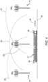
- Figure 4 is a pictorial diagram of a vehicle-to-ground wireless connection.
- a vehicle in particular a train 17 is moving in travelling direction 16 along the pathway 10, i.e. a rail track.
- a plurality of wayside base stations 9 are arranged.
- the train 17 is equipped with an on-board mobile radio station (not indicated in the figure) operatively coupled to a first and a second on-board mobile antenna 18, 19, which are preferably designed to create a directional radiation pattern.
- Each of wayside base stations BS 1 , BS 2 , BS 3 ... defines a radio coverage area of radio communication, which is pictorially illustrated with areas 20, 21 and 22.
- Near adjacent base stations operate at different frequencies.
- BS 1 and BS 3 operate at frequency f1
- BS 2 operate at frequency f2.
- the base stations 9 along the pathway 10 are arranged such as the coverage areas of at least two near adjacent base stations which operate at different frequencies partially overlap one another in the direction of the pathway and coverage areas of two subsequent base stations along the pathway and operating at the same frequency (e.g. BS 1 , BS 3 ) partially overlap one another in the direction of the pathway 10, resulting in a coverage redundancy with overlapping area 23 between radio coverage areas 20 and 21.
- FIG. 5 is pictorial diagram showing a train mounting a mobile radio station.
- the mobile radio station comprises a first radio unit, M 1 and a second radio unit M 2 , which are located in the train at a distance from one another along the train length.
- the mobile radio station is placed on-board of the train 17 and moves together with the train, possibly at a relevant speed such as in case of high speed trains, e.g. 250-350 km/h.
- Each mobile radio unit comprises a mobile receiver and a mobile transmitter, i.e. a transceiver.
- Each mobile radio unit M 1 , M 2 is operatively connected with a respective first and second mobile antenna 18, 19.
- the mobile antennas 18, 19, which are typically positioned in the same portion of the train length as the respective radio units.
- the first and second antennas 18, 19 are located at a distance d RU from one another along the train length. More generally, the first antenna 18 and the second antenna 19 are located in the vehicle at a distance from one another taken in the travelling direction 16 (along pathway 10).
- the first mobile antenna 18 is positioned on a front part of the moving train 17 with reference to the travelling direction 16.
- the second antenna 19 is positioned behind the first antenna 18 along the length of the moving train 17 taken in the travelling direction 16.
- the head antenna is mounted on a front part of the moving train, while the second antenna 19 is mounted on a rear part of the moving train, the first and second mobile antennas being positioned at the distance d RU from one another.
- first and second mobile antennas 18, 19 are directional antennas designed to create a directional radiation pattern and they are mounted on the train so that their radiation patterns point two opposite directions, one of the two opposite directions being in the moving direction 16.
- the first antenna 18 at the front of the train 17 points the travelling direction 16, taken as the positive direction, while the second antenna 19 points a direction opposite to the travelling direction 16.
- the mobile antennas 18, 19 are located on top of the train 17 for radio communication with the wayside base stations.
- the first antenna 18 will be referred also to as head antenna and the second antenna 19 will be referred also to as tail antenna.
- the terms “front” or “head” and “rear” or “tail” depend on the travelling direction and are defined relative to the travelling direction.
- the second mobile antenna 19 may act as head antenna when the train moves in a direction opposite to direction 16.
- the head antenna 18 is placed on the head coach of the train 17 and the tail antenna 19 is placed on the tail coach of the train that may have any number of coaches.
- the first radio unit at the front part of the train will be also referred to as head radio unit (or briefly head RU) and the second radio unit placed at the rear part of the train to as tail radio unit (or briefly tail RU).
- head radio unit or briefly head RU
- tail radio unit or briefly tail RU
- FIG. 6 illustrates an on-board scheme of a mobile radio station mounted on a train, according to an exemplary embodiment of the invention.
- a mobile radio station 40 comprises a first mobile RU M 1 and a second mobile RU M 2 , each RU being configured to transmit and receive radio signals, in particular RF signals, by means of a respective transmitter and receiver, indicated as transceiver 46.
- the first mobile RU M 1 comprises a first mobile receiver and the second mobile RU comprises a second mobile receiver.
- Each RU M 1 , M 2 comprises a respective electronic processor 47, which includes the functionalities for wireless network access via the transceiver 46 as well as functionalities for processing data/signals as described herein including the control of the frequency switch of the transceiver between the two frequencies.
- Electronic processor can be a microprocessor, such as a microprocessor having a MIPS (Microprocessor without Interlocked Pipeline Stages) or an x86 architecture.
- the first mobile RU M1 is connected to the first moving antenna 18.
- the second mobile RU M2 is connected to the second moving antenna 19.
- M 1 and M 2 may be connected respectively to the first and the second moving antenna 19 through two RF connectors 45a, 45b via respective coaxial cables 42.
- Various RF connectors can be used including N-type, SMA, RP-SMA, QMA, etc.
- each of the first and the second moving antenna 18, 19 is a MIMO 2x2 dual-polarised antenna, such as a shark-fin antenna.
- Each mobile radio unit M 1 , M 2 is configured to receive incoming RF signals and in particular hello packets at a radio frequency selected between the first frequency f1 and the second frequency f2.
- the mobile radio units are set to operate at different frequencies.
- the mobile radio receivers may be set to receive hello packets at different frequencies so that when a radio unit operates at the first frequency, the other radio unit operates at the second frequency and vice versa.
- Each mobile radio unit is configured to switch operating frequency from f1 (f2) to f2 (f1), in particular to dynamically change the operating frequency between the two frequencies f1 and f2.
- the transceiver 46 is configured to receive, from the respective electronic processor 47, control signals commanding the frequency switch.
- the first and the second mobile radio units M 1 , M 2 are operatively connected to an on board network system 43 for signal distribution and/or access.
- the network system 43 may be a wireless local area network (W-LAN) that include typical devices for signal distribution and/or wireless access, such as one or more wireless routers, a modem and a plurality of Wi-Fi access points to be deployed within the train in order to allow wireless devices, such as smartphone or tablets, to access the Internet by using the on board network system 43, in particular for broadband applications.
- WLAN wireless local area network
- radio communication can be instead tailored to implement an automatic train control system that makes use of telecommunications between a mobile radio station installed in the train and the base stations on the ground for traffic management and infrastructure control.
- a system for Communications-based train control (CBTC) signal management with an integrated wireless communication network system 43 typically based either on the Wi-Fi standard, a wired CBTC communication system, or on a proprietary technology.
- the mobile radio units M 1 , M 2 communicate with the network system 43 through a communication interface 41, in particular an Ethernet switch, such as an N-port Ethernet switch. More generally, the communication interface 41 is configured to provide cabled connectivity among the on-board network devices including the mobile base stations and Wi-Fi access points.
- a communication interface 41 in particular an Ethernet switch, such as an N-port Ethernet switch.
- the communication interface 41 is configured to provide cabled connectivity among the on-board network devices including the mobile base stations and Wi-Fi access points.
- each mobile radio unit M 1 , M 2 of the mobile radio station on board the moving train is set at one of the two operating frequencies f1, f2 and receives radio signals from at least one wayside base station transmitting at the same frequency.
- the first and/or the second mobile RU may receive radio signals from more than one base station, such as from two or more neighbour base stations transmitting at the frequency at which the RU is set.
- the wayside base stations in radio communication with the first and/or the second RU at the instant or time frame considered are referred in the present description and claims referred to as neighbour base stations.
- Non-neighbour base stations are those base stations of the plurality of wayside base stations, which, at the instant or time frame considered, either do not transmit or transmit signals that are low enough to be considered noise.
- the plurality of neighbour base stations of a mobile radio unit is typically a sub-plurality of the plurality of base stations deployed along the pathway 10, typically a small number m ⁇ n, for example from 1 to 3 base stations. In the present configuration, only the neighbour base station transmitting at the frequency corresponding to the frequency set at the mobile radio unit are communicating neighbour base stations.
- the pair ⁇ M x , BS y > can be seen as a combination of nodes defining a radio communication.
- Each wayside base station BS y of the N base stations is configured to periodically transmit hello packets including identity information of the base station transmitting the hello packet.
- Identity information of a hello packet is represented by a unique identifier identifying the base station, ID-BS y .
- Hello packets are transmitted on the first frequency f1 or on the second frequency f2 in accordance with the above indicated arrangement of the plurality of base stations along the pathway 10.
- Each mobile radio unit M 1 , M 2 of the mobile radio station is configured to receive hello packets transmitted from the same-frequency neighbour base stations and to measure the signal strength of each hello packet received.
- the information on the signal strength emitted from a base station are typically represented by an RSSI (Received Signal Strength Indicator) value.
- the periodical transmission of hello packets may take place in a frame of unsolicited data packet broadcast, according to known standards in wireless communication, for example in Wi-Fi standards IEEE 802.11.
- each wayside base station may be configured to transmit hello packets with a periodicity of 10 packets per second.
- each mobile radio unit M x is configured to perform neighbour discovery, by monitoring continuously the signals received from the neighbour base stations, for example by using known discovery protocols of wireless communication standards.
- the transmitter of each mobile RU is configured to repeatedly transmit discovery requests, such as probe requests or probe request frames in case of standards IEEE 802.11, to inform the neighbour base stations about its existence.
- Neighbour base stations are configured to respond to the probe request frames by transmitting solicited hello packets, which are received by the receiver of a mobile RU.
- the wireless communication between a wayside base station and the on-board mobile radio station takes place on a single communication link.
- a single communication link is established between one wayside base station and one mobile radio unit of the mobile radio station.
- the communication between the mobile radio station and the wayside base stations is managed through a single radio communication link.
- First and second radio units M 1 , M 2 repeatedly receive hello packets periodically transmitted from the neighbour base stations in radio communication with one or both mobile radio units. Since the head radio unit and the tail radio unit can receive signals from base stations operating at the same frequency as that of the radio unit, in many cases, each mobile radio unit is in radio communication with a sub-plurality of neighbour base stations.
- each mobile radio unit For each received hello packet, each mobile radio unit is configured to measure and store the signal strength of a received hello packet as an RSSI value.
- the respective electronic processor 47 connected to the transceiver 46 of the first or second radio unit is configured to receive from the transceiver 46 the radio signal associated with the hello packet and to determine the RSSI value of the electric signal.
- the RSSI values determined from the first and the second electronic processors 47 are stored in a memory space (not indicated in the figures) operatively coupled with each of the processors 47 or part of one of the two processors.
- one of the two electronic processors 47 is elected as master of the execution of the software code that stores the signal strength values received from both mobile radio units and manages the handoff procedures.
- the processor 47 selected as master is hereafter referred to as master processor.
- the other processor 47 is indicated as slave processor.
- Both the master and slave RU processors 47 are configured to receive radio signals, such as hello packets, from the respective radio unit and to determine the RSSI values of the received hello packets.
- both the master and slave processors 47 are programmed to command the frequency switching operation.
- Transmission of the data from the slave processor to the master processor may take place through the on-board switch 41 via the cabled connection 44.
- the master processor can "master" the handoff process for both radio units.
- the designation of a RU as master and thus of the other RU as slave may take place automatically at the initialisation of the mobile radio station, e.g. when the mobile radio station is powered up, according to known algorithms, such as election algorithms, for example a Bully Algorithm.
- Figure 7 is a diagram of the train-to-ground wireless connection at the vicinity of a base station 9 to pictorially and schematically represent the entry to and exit from a keyhole in association with the relative position of a train and thus of the radio units of the mobile radio station. Same numbers indicate the same or similar features shown in previous drawings. For the sake of simplicity, a single base station is considered.
- the passing of the train through a wayside base station 9 may be divided in four main phases (i) to (iv):
- the head radio unit M 1 is typically the first to approach a base station and thus to enter the keyhole of that base station.
- the head radio unit M 1 is set to operate at one of the two frequencies, e.g. the first frequency f1 and, at a certain instant of time, is in a current radio communication link with a current base station BSc set at the first frequency f1.
- the head radio unit repeatedly receives hello packets periodically transmitted from the current base station BS c and, by means of processor 47 to determine the RSSI values associated with the received hello packets.
- the RSSI values associated with the current base station BS c are stored in a memory space operatively coupled with the master processor and repeatedly analysed by the master processor to determine whether a RSSI value is larger than a threshold signal strength value, TH.
- the threshold RSSI value TH is a numerical indication that the head radio unit is inside the keyhole of the current base station BS c .
- the tail radio unit M 2 If the tail radio unit is set at the second frequency f2, while the head radio unit M 1 is in radio communication link with the current base station at f1, the tail radio unit M 2 repeatedly receives hello packets periodically transmitted from one or more neighbour base stations set at the second frequency f2.
- the electronic processor 47 operatively coupled to the tail radio unit determines the RSSI values associated with the received hello packets and, if this electronic processor is elected as master processor, it stores the RSSI values in the memory space. If the electronic processor of the tail radio unit is elected as slave processor, it will send the RSSI value to the master processor for the storing.
- Any RSSI value relative to the head and the tail radio unit is stored in association with a respective base station identifier and a respective radio unit identifier.
- each RSSI value is associated with a pair ⁇ M x , BS y >.
- the RSSI values and the associated base station identifiers and radio unit identifiers are stored in a neighbour table as table entries.
- the base stations included in the neighbour table are neighbour base stations and, depending on the frequency set at the mobile radio units, may be handoff candidate base stations for either or both the head or the tail radio units.
- the received hello packets from the neighbour base stations vary in strength and this causes the processor to repeatedly change the signal strength values stored in the neighbour table.
- the slave processor is programmed to measure the RSSI of the received hello packets and transmits in real time the determined RSSI values to the master processor which then enters them into the neighbour table.
- the slave RU will transfer the data based on the received hello packet to the master processor, which is programmed to input the information into the neighbour table.
- the neighbour table is updated by means of a table update procedure run by the master processor anytime a hello packet is received, the hello packet including a base station identifier of the base station transmitting it and being stored in association with the radio unit identifier of the mobile RU that has received the hello packet.
- Table 1 Mobile RU Base Station ID RSSI value ID-M 1 ID-BS 2 RSSI 12 ID-M 2 ID-BS 1 RSSI 21 ID-M 2 ID-BS 2 RSSI 22 ID-M 1 ID-BS 3 RSSI 13
- the table is preferably a dynamic read table automatically updated when a new hello packet is received by either the head radio unit or the tail radio unit.
- a new row is added in the table when the entry pair ⁇ M x , BS y > is not present in the table (i.e. no existing radio communication between M x and BS y ) or an existing row representing the radio communication ⁇ M x , BS y > is updated when a new value of RSSI is measured by the mobile receiver M x in the hello packet from BS y .
- the master processor 47 is programmed to automatically enter, in real time at the reception of a hello packet the new information in the table.
- the slave processor may be programmed to send the information on the RSSI xy values as entry pair ⁇ M x , BS y > to the master processor.
- the neighbour table is preferably stored in a non-transitory memory space operatively coupled with the master processor or part of the master processor.
- the master processor may be programmed to delete a row from the neighbour table if the value of the RSSI of that row has not been updated for a preset time interval.
- the table may include a timestamp, e.g. stored in an additional column, associated to the time at which the RSSI value has been entered and, when a preset time interval between the entry time and the actual time is larger than a predetermined time value, the row containing the "old" RSSI value is deleted from the table.
- a timestamp e.g. stored in an additional column, associated to the time at which the RSSI value has been entered and, when a preset time interval between the entry time and the actual time is larger than a predetermined time value, the row containing the "old" RSSI value is deleted from the table.
- the neighbour table is frequency agnostic. More generally, the handoff procedure based either on the detection of a RSSI value larger than a threshold or on the best RSSI value is frequency agnostic because at any time the radio communication can take place only over a same frequency.
- each mobile radio unit may comprise a computer-readable storage medium operably connected to the electronic processor, the computer-readable storage medium configured to store instructions executable by the processor and data accessible by the processor.
- the electronic processor is programmed to repeatedly query the neighbour table to determine the current RSSI value, RSSI c , and to compare the RSSI c value with a given threshold value of RSSI, TH.
- a handoff trigger is generated and the electronic processor is programmed to proceed with:
- a timer is set, which starts a time interval indicated as keyhole time duration ⁇ t k .
- the current communication link is between the tail radio unit and the first destination base station BS d1 .
- the handoff triggers also a frequency switch in the head radio unit M 1 from the first frequency f1 to the second frequency f2.
- the electronic processor is programmed to command the initialization of a frequency switching operation in the head radio unit to switch the frequency from f1 to f2.
- the head radio unit M 1 is configured to receive hello packets from neighbour base stations operating at the second frequency f2.
- the setting of the timer starting the keyhole time duration and the frequency switching operation in the first mobile radio unit may take place simultaneously upon handoff from the first radio unit to the second radio unit.
- the head radio unit (but the same can be said for the tail radio unit), is inactive as it is unable to carry out the main functionalities of receiving and transmitting radio signals.
- the electronic processor is notified by the head radio unit once the frequency switching operation is completed and thus that the head radio unit is again active and capable of receiving hello packets.
- the time required for a frequency switching operation from f1 to f2 and viceversa in a radio unit generally depends on the radio hardware equipment and may widely vary, for example from less than 1 millisecond (ms) to more than 400 ms.
- Frequency switching speed in a commercial radio unit may be known as product specification or may be inferred from the time between the initialization of the frequency switching and the notification to the electronic processor that the operation has been completed.
- the first radio unit M 1 is configured to receive hello packets from the neighbour base stations set at the second frequency f2. Therefore, both radio units are temporarily configured to receive hello packets over the second frequency f2 and the neighbour table contains entries relative to both M 1 and M 2 .
- the keyhole duration which may be selected on the basis of the configuration of the base station system, is significantly larger than the expected time required for the frequency switching operations in the head or tail radio units.
- the keyhole time duration ⁇ t k is a predetermined time value, for example of from 10 to 20 seconds.
- the second radio unit Mz in radio communication link with the first destination base station BS d1 continues to receive hello packets from neighbour base stations set at the second frequency f2, the neighbour base stations including the first destination base station BS d1 .
- the best signal strength value of the base stations transmitting at the second frequency f2 is searched with the aim of performing a handoff from the first destination base station BS d1 and possibly from the tail radio unit M 2 if a determined highest signal strength value is associated with a base station other than BS d1 . If, at a certain time during the keyhole duration, the best RSSI value is determined to be associated with a second destination base station BS d2 , other than BS d1 , this best RSSI value may be received by either the head or the tail radio unit.
- the electronic processor upon setting of the timer starting the keyhole duration ⁇ t k , is programmed to repeatedly query the neighbour table to determine in the stored RSSI values the highest RSSI value and, in case a highest RSSI value is associated with a base station other than BS d1 , to force a handoff from the first destination base station BS d1 to a second destination base station BS d2 .
- the electronic processor is programmed to force a handoff from the first destination base station BS d1 to the second destination base station BS d2 . If the mobile radio unit associated with the second destination base station BS d2 is the first radio unit M 1 , the handoff comprises a handoff from the tail radio unit M 2 to the head radio unit M 1 . A new radio communication link is then established between the second destination base station BS d2 and one of the head and the tail radio unit.
- the check on the threshold RSSI value may be carried out also during the keyhole duration. However, in most practical cases, the event that the threshold value is exceeded by the base station in current communication link with a mobile radio unit is not very likely to occur.
- No handoff or more than one handoff may take place during the keyhole time duration.
- the current radio communication link between a current base station may be associated with the head radio unit M 1 or with the tail radio unit M 2 .
- the electronic processor 47 is programmed, upon lapse of ⁇ t k , to determine if the current radio communication link is associated with the head radio unit or the tail radio unit.
- the electronic processor is programmed to command the tail radio unit M 2 to execute a frequency switching operation to switch the frequency from f2 to f1.
- the tail radio unit M 2 is configured to receive hello packets from neighbour base stations operating at the first frequency f1.
- the electronic processor upon lapse of ⁇ t k , if the current radio communication link is determined to be associated with the tail radio unit M 2 , the electronic processor is programmed to command a frequency switching operation in the tail radio unit M 2 to switch the frequency from f2 to f1. During the switching operation in the tail radio unit M 2 , the tail radio unit Mz is unable to communicate with any base station.
- the algorithm preferably proceeds with the search of the best RSSI value, i.e. the highest RSSI value in the neighbour table, associated with either M 1 or Mz.
- the tail radio unit As a time interval has passed from the forced handoff from the base station having an RRSI above threshold as received by the head radio unit, the tail radio unit is expected to have passed through that base station and thus to receive hello packets over the first frequency f1 (also) from that base station. Thus, the best signal is likely to be (yet not necessarily) that received by the tail radio unit and associated the base station BS c previously excluded because above threshold.
- disconnection from the current communication link in the tail radio unit during frequency switching generally involves minimal traffic disruption when the time required for the switching operation is relatively short, for example less than about 2-3 ms.
- the time required to set the tail radio unit to a different radio frequency is relatively long, for example larger than 5 ms and in particular larger than 10 ms, disconnecting the current link in the tail radio unit during the frequency change may be perceived as a service quality deterioration by the users connected with the mobile radio station.
- the electronic processor upon lapse of keyhole time duration ⁇ t k , if the current radio communication link is determined to be associated with the tail radio unit M 2 , the electronic processor is programmed to:
- the tail radio unit M 2 At the end of the switching operation in the tail radio unit M 2 , wherein the current communication link is associated with the first radio unit M 1 at f2, the tail radio unit starts receiving hello packets over the first frequency f1.
- the algorithm preferably proceeds with the search of the best RSSI value, i.e. the highest RSSI value in the neighbour table, associated with either M 1 or Mz. Also in this case, the best signal is likely to be (yet not necessarily) that received by the tail radio unit and associated the base station BS c previously excluded because above threshold.
- the electronic processor while repeatedly querying the neighbour table to determine the highest signal strength value, is programmed to carry out the iterative analysis of the RSSI values of the current base station to determine if an RSSI value exceeds the threshold value and, in the positive, to force a handoff from the head radio unit to the tail radio unit and to a neighbour base station in communication with the tail radio unit.
- the electronic processor is programmed to command the removal of all entries associated with the head (tail) radio unit from the neighbour table.
- the head radio unit since the head radio unit is the first radio unit to approach a base station in the moving direction, performing a handoff to the tail radio unit when the latter is not affected by the keyhole effect of that base station and then back to the head radio unit prevents or reduces loss of data transfer occurring periodically at the positions of the base stations.
- Figure 8 is an exemplary graph reporting the downlink signal strength (RSSI) of neighbour base stations plotted as a function of time as measured by an on-board mobile radio station of the type shown in Fig. 4 , which is mounted on a train moving in a subway tunnel in the moving direction from left to right of the graph (time line).
- RSSI value TH
- TH is a predetermined constant value indicated with a horizontal line.
- the graph of Fig. 8 shows the RSSI signals received by the mobile station in a section of the rail track run by the moving train.
- neighbour base stations for the mobile radio station are BS 1 , BS 2 and BS 3 .
- Solid line represents the RSSI from BS 1 , as received by the tail RU Mz from the rear antenna at the end of the train.
- the dotted line represents the RSSI received by the head RU M 1 from the front antenna at the head of the train from base station BS 2 , which is positioned near adjacent to BS 1 in the moving direction, i.e. consecutive to BS 1 in the moving direction.
- the dashed line is the RSSI of the third base station BS 3 , as measured by the head RU M 1 receiving the signal from the head antenna.
- the dashed-dotted line represents the RSSI received by the tail RU M 2 from base station BS 2 , which is positioned near adjacent to BS 2 in the moving direction.
- BS 1 and BS 3 and operate at the first frequency f1
- BS 2 operates at the second frequency f2.
- Figure 8 shows also the current communication link (diamond symbols) resulting from the application of a handoff algorithm according to an exemplary embodiment of the present disclosure.
- the tail RU Mz is set to receive packets over frequency f1
- the head RU M 1 is set to receive packets over frequency f2
- the radio communication link is between M 2 and BS 1 .
- a handoff H1 is performed from the current base station BS 1 to base station BS 2 , which has a higher RSSI value than BS 1 , as the train is approaching BS 2 with the head antenna.
- Handoff H1 is based on the best signal strength of the neighbour stations when RSSI values of the current base station (BS 1 ) are determined to be smaller than or equal to the TH value.
- the signal strength associated with BS 2 increases as the head RU M 1 approaches the location of the base station.
- a handoff H2 is forced from the head RU M 1 to the tail RU M 2 by establishing a link between the tail RU M 2 and base station BS 1 as first destination base station with the best signal strength among the neighbour base stations transmitting hello packets over frequency f1 (pair ⁇ Mz, BS 1 >).
- the head RU M 1 switches frequency from f2 to f1 and a timer is triggered, the timer expiring after a time interval indicated above as keyhole duration ⁇ t k .
- a handoff H3 which is based on the best signal strength, takes place from the tail RU M 2 to the head RU M 1 and from BS 1 to BS 3 as second destination base station, when the signal strength of BS 3 exceeds that of BS 1 (i.e. new pair ⁇ M 1 , BS 3 >).
- This scenario thus assumes that, at the end of the keyhole duration, the current communication link is associated with the head radio unit.
- the time required for the switching operation in the tail radio unit is largely not relevant because the radio communication takes place with the head radio unit.
- the tail RU M 2 switches frequency from f1 to f2.
- a connection may be established according to the pair having the highest signal strength.
- both the head radio unit M 1 and the tail radio unit M 2 have passed the keyhole at BS 2 and the tail radio M 2 may connect to the base station BS 2 .
- the tail radio M 2 may connect to the base station BS 2 .
- a handoff H4 based on the best signal strength takes place to base station BS 2 that has the strongest signal.
- both the head and the tail radio units are configured to operate on frequency f1 so that they are excluded from receiving RF signals from the formerly current BS 2 transmitting over f2 while they are enabled to connect to base stations adjacent to BS 1 , which typically have a reasonably good quality signal.
- the RSSI of BS 2 may exceed the threshold value TH since the train has already passed through the location of BS 2 and thus it has exited from the keyhole.
- a condition exists according to which, when the keyhole duration ends, the base station previously cut-off from the mobile radio units is again a candidate for the handoff for the radio unit receiving at the frequency of BS 2 . More generally, a base station cannot be consecutively excluded more than once. This condition expresses the high likelihood that, when exiting the keyhole, the best signal is that of BS 2 because the mobile receiver is still positioned at the proximity of that BS 2 , but outside the keyhole.
- the electronic processor when querying the neighbour table to select the highest signal strength value, determines whether the highest signal strength value is associated with the formerly cut-off base station and, in the positive, forces a handoff to the formerly cut-off base station.
- Figure 9 illustrates a further example of a handoff process in a second network scenario, in which it is assumed that at the end of the keyhole duration ⁇ t k the current communication link is established with the tail radio unit M 2 , which is designed to perform a "fast" frequency switching operation.
- the time scale has been expanded relative the scale of Fig. 8 .
- the tail RU M 2 is set to receive packets over frequency f1
- the head RU M 1 is set to receive packets over frequency f2
- the radio communication link is between M 2 and BS 1 .
- the RSSI values of the current base station BS 1 do not exceed the TH value and as the train is approaching BS 2 with the head antenna, at a certain time, a handoff H1 is performed from the current base station BS 1 to base station BS 2 , since BS 2 has reached a RSSI value higher than BS 1 . Therefore, handoff H1 is based on the best signal strength of the neighbour stations.
- the signal strength associated with BS 2 increases as the head RU M 1 approaches the location of the base station.
- a handoff H2 is forced from the head RU M 1 to the tail RU M 2 by establishing a communication link between the tail RU M 2 and base station BS 1 as first destination base station with the best signal strength among the neighbour base stations transmitting packets over frequency f1.
- the head RU M 1 switches frequency from f2 to f1 and a timer is triggered to expire after a predetermined keyhole duration ⁇ t k .
- the current communication link between the tail RU M 2 and BS 1 is maintained because BS 1 remains the base station having the best signal strength.
- the lapse of the keyhole duration ⁇ t k triggers a frequency switching operation in the tail RU M 2 from f1 to f2. Since the radio communication link is still associated with M 2 , the switching operation causes a relatively short service disruption, in the example of less than 2 ms, during which the radio unit is inactive and is unable to receive signals from the base station to which it was in communication and thus no RSSI values can be measured.
- the period of inactivity of M 2 starts at a time corresponding to the end of ⁇ t k , indicated with dashed vertical line 49.
- the radio communication with BS 1 is interrupted because of the change of frequency.
- the tail radio unit notifies its activity and starts receiving signals from the neighbour base stations transmitting over frequency f2. This causes a handoff of tail RU to a base station having the best signal.
- a handoff H3 sets in radio communication link the tail radio unit M 2 with base station BS 2 .
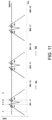
- Figure 10 illustrates a still further example of a handoff process in a third network scenario, in which it is assumed that at the end of the keyhole duration the current communication link is established with the tail radio unit M 2 , which is designed to perform a "slow" frequency switching operation.
- the time scale correspond to that of Fig. 9 .
- the same graphic symbols are used to indicate the same pairs ⁇ M x , BS y > and the current communication link.
- the handoff process corresponds to that of Fig. 9 up to the end of the keyhole duration ⁇ t k .
- the time ⁇ t sw required for the frequency switching operation is relatively long and would cause a non-negligible service disruption.
- a handoff H3 is forced to the head radio unit M 1 set at frequency f1 in communication with a neighbour base station having the best signal strength of the base stations transmitting over f1.
- M 1 receives hello packets with having a significant signal strength only from BS 3 .
- the tail radio unit M 2 notifies its activity at frequency f2. The best signal strength is searched among the neighbour stations transmitting over frequency f2 and f1.
- BS 2 transmitting at f2 has the best signal strength and a handoff H4 is forced to put the tail RU M 2 in radio communication link with BS 2 .
- the handoff algorithm running in the electronic processor is aware of which of the two mobile radio units is the head radio unit in the moving direction, in practice the radio unit placed at the front of the vehicle relative to the moving direction.
- This information may be provided by a user as input data into a user interface connected to the mobile radio station, in particular with the electronic processor mastering the handoff process, or it may be provided by the vehicle IT equipment operatively connected with the mobile radio station.
- a GPS system mounted on the vehicle may transmits the information to the mobile radio station.
- the head detection procedure may be implemented as a starting phase before initialization of the handoff process herein described.
- the first and second radio units are set to receive RF signals and in particular hello packets over the same frequency, for example f1.
- both mobile radio units receive hello packets from base stations BS 1 , BS 3 , BS 3 , and so on.
- Figure 11 is a conceptual diagram illustrating the behaviour of the RSSI received from the "odd" base stations BS 1 , BS 3 , BSs... as a function of time as seen by the radio units.
- the "even" base stations BS 2 , BS 4 ...operate at f2 and therefore they are not “visible” by the radio units.
- No frequency switch is executed during the head detection procedure.
- a head detection algorithm which may run in the (master) electronic processor of the mobile radio station, is initialised when the train starts moving.
- the electronic processor is programmed to analyse the received RSSI values associated with respective base station identifiers and the radio unit identifiers and to determine if an RSSI value is larger than a threshold RSSI value.
- the head detection algorithm uses a standard handoff algorithm based on the best signal strength for the handoff from one base station to an adjacent base station having the same frequency.
- the occurrence of a signal received by the head or the tail radio units having an RSSI value larger than the threshold value causes a trigger event that is registered in a memory space associated with the electronic processor. Each trigger event is stored in association with the base station identifier and a radio unit identifier, without the knowledge if that identifier indicates the head or the tail radio unit.
- the electronic processor is programmed to count the number of times a same radio unit experiences a trigger event. At the occurrence of two consecutive trigger events by the same radio unit, the electronic processor is programmed to determine that that mobile radio unit is the head radio unit. For example, when the radio unit is determined to be the head radio unit, the electronic processor is caused to associate an identifier to the radio unit identifying the same as the head radio unit.
- solid line indicates a sequence of events for a first radio unit Mi
- dashed line indicates a sequence of events for a second radio unit Mj.
- a first radio unit Mi is in radio communication link with the first base station BS 1 and the train moves across section AB of the pathway while approaching BS 1 .
- the RSSI of the signal received by radio unit Mi exceeds threshold TH and a first trigger event is registered in association with radio unit Mi.
- the radio unit Mi travels and the best signal remains that from BS 1 to Mi (i.e. no handoff to the other radio unit Mj).
- the signal strength of BS 2 exceeds the signal strength of BS 1
- a radio communication link is established between Mi and BS 2 .
- the signal strength received from Mi exceeds the threshold and a second trigger event is registered in association with radio unit Mi.
- the electronic processor determines that Mi is the head radio unit M 1 .
- a second radio unit Mj is in radio communication link with the first base station BS 1 in section BD of the pathway, corresponding to a keyhole position as seen from radio unit Mj.
- radio unit Mj receives a signal with a signal strength larger than TH and a first trigger event is registered.
- the train travelling, Mi receives a stronger signals than Mj and a radio communication link is established between Mi and BS 3 .
- a trigger event takes place at position P3, at the proximity of BS 3 , which is associated with a different radio unit than that associated with the first registered trigger event.
- the electronic processor is configured to register the trigger event at P3 as first trigger event for radio unit Mi. As the train travels, radio unit Mi approaches BS 5 and, based on the detection of the best signal, a handoff is forced and a radio communication link is established between Mi and BS 5 and at position P5 the signal strength exceed TH.
- the electronic processor is programmed to register the trigger event in association with radio unit Mi and to determine that it is the second consecutive trigger event for radio unit Mi. At the occurrence of the second consecutive trigger event associated with the same radio unit (Mi), the electronic processor determines that Mi is the head radio unit M 1 .
- the communication link is between Mj and BS 1 , with Mj positions in section DE, outside the keyhole of BS 1 .
- a communication link between Mi and BS 2 is established when the train approaches (with its head) BS 2 .
- two consecutive trigger events in association with Mi take place, in this case at P3 and P5 leading to the determination of Mi as the head radio unit.
- Figure 12 is a flow chart depicting an example of a handoff procedure consistent with an embodiment of the present disclosure.
- Flow chart 60 exemplifies a procedure that starts from an event in the head radio unit M 1 in radio communication link with current base station BS c of a received signal strength value determined to be larger than the threshold signal strength value, TH (block 61).
- the event at block 61 triggers a forced handoff to the tail radio unit M 2 in connection with a base station BS x so as to establish a radio communication link ⁇ Mz, BS x > (block 62).
- a frequency switching operation is executed to switch in the first radio unit M 1 the first frequency f1 to the second frequency f2 and a timer is set for a time defining a keyhole time duration ⁇ t k (block 63).
- a handoff based on the best signal strength takes place so that at the expiry of the keyhole time duration the current communication link may be associated with either mobile radio unit (not indicated).
- the procedure comprises determining if the current radio communication link is associated with the first radio unit M 1 (block 65).
- a frequency switching operation is executed to switch in the second radio unit M 2 the second frequency f2 to the first frequency f1 (block 66).
- the procedure ends (block 67) to start again when an event of RSSI value exceeding the threshold value TH occurs in one of the two mobile radio units. As far as this event does not occur, handoff may be based on the best signal strength value.
- the switch in M 2 is executed (block 71) and the procedure ends (block 67).
- a handoff is forced from M 2 to M 1 so as to establish a communication link between M 1 and a base station having the best signal strength value (block 69).
- the switch in M 2 is executed (block 72) and the procedure ends (block 67).
- the decision in block 68 does not need to be made every time the handoff procedure triggered by the keyhole occurrence is carried out.
- the algorithm may be set to always execute operation 71 or 69 and 72 when the current link is determined, at block 65, to be associated with Mz.
- the electronic processor is programmed to maintain the current communication link in the second radio unit M 2 .
- the electronic processor is programmed to switch the frequency from f2 to f1, possibly after having forced a handoff to M 1 .
- the flow chart would not comprise block 65.
Landscapes
- Engineering & Computer Science (AREA)
- Computer Networks & Wireless Communication (AREA)
- Signal Processing (AREA)
- Mobile Radio Communication Systems (AREA)
Claims (15)
- Verfahren zum Verwalten einer Funkkommunikationsverbindung zwischen einer Mobilfunkstation (40) und einer Vielzahl von festen, wegseitigen Funkbasisstationen, die räumlich getrennt entlang eines Weges angeordnet sind, wobei sich die Mobilfunkstation in einer Fahrtrichtung (16) entlang des Weges (10) in Bezug auf die Basisstationen bewegt, wobeijede der Basisstationen so eingestellt ist, dass sie auf einer jeweiligen Funkfrequenz arbeitet, die aus einer ersten Frequenz (f1) und einer zweiten Frequenz (f2) ausgewählt wird, und die Basisstationen so angeordnet sind, dass nahe angrenzende Basisstationen auf abwechselnde Frequenzen eingestellt sind,die Mobilfunkstation (40) eine erste Mobilfunkeinheit (M1) und eine zweite Mobilfunkeinheit (M2) aufweist, die in der Fahrtrichtung (16) räumlich getrennt sind, wobei die erste und die zweite Mobilfunkeinheit jeweils zum Empfangen von Funksignalen auf einer von der ersten und der zweiten Frequenz konfiguriert sind, wobei das Verfahren Folgendes aufweist:a) in jeder Basisstation der Vielzahl von Basisstationen periodisches Übertragen von Begrüßungspaketen an die Mobilfunkstation (40), wobei jedes Begrüßungspaket eine Basisstationskennung enthält, die die Basisstation, die das Begrüßungspaket überträgt, eindeutig kennzeichnet;b) in der ersten Mobilfunkeinheit (M1), die auf die erste Frequenz (f1) eingestellt ist, und in einer aktuellen Funkkommunikationsverbindung mit einer aktuellen Basisstation (BSc), die auf die erste Frequenz (f1) eingestellt ist, Empfangen von Begrüßungspaketen von ein oder mehr Nachbar-Basisstationen, die auf die erste Frequenz (f1) eingestellt sind, wobei die Nachbar-Basisstationen die aktuelle Basisstation (BSc) beinhalten und in der Vielzahl von Basisstationen enthalten sind;c) in der zweiten Mobilfunkeinheit (M2), die auf die zweite Frequenz (f2) eingestellt ist, Empfangen von Begrüßungspaketen von ein oder mehr Nachbar-Basisstationen, die auf die zweite Frequenz (f2) eingestellt sind und in der Vielzahl von Basisstationen enthalten sind;d) in der Mobilfunkstation (40) Bestimmen jeweiliger Signalstärkenwerte für die von der ersten Mobilfunkeinheit (M1) und der zweiten Mobilfunkeinheit (M2) empfangenen Begrüßungspakete und Speichern der bestimmten Signalstärkewerte, wobei jeder Signalstärkewert in Zuordnung zu einer jeweiligen Basisstationskennung und einer jeweiligen Funkeinheitskennung, die die Mobilfunkeinheit kennzeichnet, die das Begrüßungspaket empfängt, gespeichert wird;e) wiederholtes Analysieren der gespeicherten Signalstärkewerte, die der aktuellen Basisstation (BSc) und der ersten Funkeinheit (M1) zugeordnet sind, um zu bestimmen, ob die Signalstärkewerte größer sind als ein vorbestimmter Schwellensignalstärkewert (TH), wobei der Schwellensignalstärkewert (TH) erkennen lässt, dass sich die erste Funkeinheit (M1) innerhalb eines Schlüssellochs der aktuellen Basisstation (BSc) befindet, und der sich auf eine Verschlechterung der Kanalkapazität bei Nutzung mehrerer Empfangs- und Sendeantennen, MIMO, bezieht;f) wenn bestimmt wird, dass ein der aktuellen Basisstation (BSc) zugeordneter Signalstärkewert größer als der Schwellensignalstärkewert (TH) ist,• Analysieren der gespeicherten Signalstärkewerte, die der zweiten Mobilfunkeinheit (M2) zugeordnet sind, zum Auswählen einer Nachbar-Basisstation, die dem höchsten Signalstärkewert zugeordnet ist, als erste Zielbasisstation (BSd1), die auf die zweite Frequenz (f2) eingestellt ist, und• Forcieren einer Verbindungsübergabe von der ersten Mobilfunkeinheit (M1) an die zweite Mobilfunkeinheit (M2) und Herstellen einer neuen Funkkommunikationsverbindung zwischen der zweiten Mobilfunkeinheit (M2) und der ersten Zielbasisstation (BSd1).
- Verfahren nach Anspruch 1, das bei Verbindungsübergabe an die erste Zielbasisstation (BSd1) Starten eines Frequenzumschaltvorgangs in der ersten Mobilfunkeinheit (M1) aufweist, um die erste Frequenz (f1) auf die zweite Frequenz (f2) umzuschalten, so dass am Ende des Frequenzumschaltvorgangs die erste Mobilfunkeinheit (M1) so konfiguriert ist, dass sie Begrüßungspakete von ein oder mehr Nachbar-Basisstationen empfängt, die auf die zweite Frequenz (f2) eingestellt sind.
- Verfahren nach Anspruch 2, das bei Verbindungsübergabe von der ersten Funkmobileinheit (M1) an die zweite Mobilfunkeinheit (M2) Folgendes aufweist:Einstellen eines Timers, der eine Schlüssellochzeitdauer (Δtk) startet;in der zweiten Funkeinheit (M2), die auf die zweite Frequenz (f2) und in einer aktuellen Funkkommunikationsverbindung mit der ersten Zielbasisstation (BSd1) als aktuelle Basisstation eingestellt ist, und in der ersten Funkeinheit (M1), die auf die zweite Frequenz (f2) eingestellt ist, am Ende des Frequenzumschaltvorgangs Empfangen von Begrüßungspaketen von ein oder mehr Nachbar-Basisstationen, die auf die zweite Frequenz (f2) eingestellt sind, wobei die Nachbar-Basisstationen die erste Zielbasisstation (BSd1) beinhalten.
- Verfahren nach Anspruch 3, das Folgendes aufweist: während der Schlüssellochzeitdauer (Δtk) Analysieren der gespeicherten Signalstärkewerte, die den von der ersten Mobilfunkeinheit (M1) und der zweiten Mobilfunkeinheit (M2) empfangenen Begrüßungspaketen zugeordnet sind, zum Bestimmen eines höchsten Signalstärkewerts und,wenn der bestimmte höchste Signalstärkewert einer zweiten Zielbasisstation (BSd2), die von der ersten Zielbasisstation (BSd1) verschieden ist, zugeordnet ist, Forcieren einer Verbindungsübergabe von der ersten Zielbasisstation (BSd1) an die zweite Zielbasisstation (BSd2), wobei,wenn die Mobilfunkeinheit, die der zweiten Zielbasisstation (BSd2) zugeordnet ist, die erste Mobilfunkeinheit (M1) ist, die Verbindungsübergabe eine Verbindungsübergabe von der zweiten Mobilfunkeinheit (M2) an die erste Mobilfunkeinheit (M1) aufweist, so dass bei Verbindungsübergabe eine neue Funkkommunikationsverbindung zwischen entweder der ersten Mobilfunkeinheit (M1) oder der zweiten Mobilfunkeinheit (M2) und der zweiten Zielbasisstation (BSd2) hergestellt wird.
- Verfahren nach Anspruch 3 oder 4, das bei Ablauf der Schlüssellochzeitdauer (Δtk) Folgendes aufweist:• Starten eines Frequenzumschaltvorgangs in der zweiten Mobilfunkeinheit (M2) von der zweiten Frequenz (f2) auf die erste Frequenz (f1), so dass am Ende des Frequenzumschaltvorgangs die zweite Mobilfunkeinheit (M2) zum Empfangen von Begrüßungspaketen von ein oder mehr Nachbar-Basisstationen, die auf der ersten Frequenz (f1) arbeiten, konfiguriert ist.
- Verfahren nach Anspruch 3 oder 4, das bei Ablauf der Schlüssellochzeitdauer (Δtk) Bestimmen, ob die aktuelle Funkkommunikationsverbindung der ersten Mobilfunkeinheit (M1) oder der zweiten Mobilfunkeinheit (M2) zugeordnet ist, aufweist,• wenn bestimmt wird, dass die aktuelle Funkkommunikationsverbindung am Ende der Schlüssellochzeitdauer der zweiten Mobilfunkeinheit (M2) zugeordnet ist, Analysieren der gespeicherten Signalstärkewerte, die der ersten Mobilfunkeinheit (M1) zugeordnet sind, die auf die zweite Frequenz (f2) eingestellt ist, zum Auswählen einer Nachbar-Basisstation, die dem höchsten Signalstärkewert zugeordnet ist, als eine vorübergehende Basisstation,• Forcieren einer Verbindungsübergabe von der zweiten Mobilfunkeinheit (M2) auf die erste Mobilfunkeinheit (M1) und Herstellen einer neuen Funkkommunikationsverbindung zwischen der ersten Mobilfunkeinheit (M1) und der vorübergehenden Basisstation und• bei Verbindungsübergabe an die erste Mobilfunkeinheit (M1) Starten eines Frequenzumschaltvorgangs in der zweiten Mobilfunkeinheit (M2) von der zweiten Frequenz (f2) auf die erste Frequenz (f1), so dass am Ende des Frequenzumschaltvorgangs die zweite Mobilfunkeinheit (M2) zum Empfangen von Begrüßungspaketen von ein oder mehr Nachbar-Basisstationen, die auf der ersten Frequenz (f1) arbeiten, konfiguriert ist.
- Verfahren nach Anspruch 6, wobei, wenn bestimmt wird, dass die aktuelle Funkkommunikationsverbindung am Ende der Schlüssellochzeitdauer der ersten Mobilfunkeinheit (M1) zugeordnet ist, Starten eines Frequenzumschaltvorgangs in der zweiten Mobilfunkeinheit (M2) von der zweiten Frequenz (f2) auf die erste Frequenz (f1), so dass am Ende des Frequenzumschaltvorgangs die zweite Mobilfunkeinheit (M2) zum Empfangen von Begrüßungspaketen von ein oder mehr Nachbar-Basisstationen, die auf der ersten Frequenz (f1) arbeiten, konfiguriert ist.
- Verfahren nach Anspruch 5 oder 7, das Folgendes aufweist: am Ende des Frequenzumschaltvorgangs in der zweiten Mobilfunkeinheit (M2) von der zweiten Frequenz (f2) auf die erste Frequenz (f1) Einstellen der ersten Funkeinheit (M1) auf die zweite Frequenz (f2) und Herstellen einer aktuellen Funkkommunikationsverbindung zwischen entweder der ersten oder der zweiten Mobilfunkeinheit und einer aktuellen Basisstation,- Analysieren der gespeicherten Signalstärkewerte, die durch die erste Mobilfunkeinheit (M1) und durch die zweite Mobilfunkeinheit (M2) empfangenen Begrüßungspaketen zugeordnet sind, zum Bestimmen eines höchsten Signalstärkewerts und,- wenn der höchste Signalstärkewert einer Basisstation, die von der aktuellen Basisstation verschieden ist, zugeordnet ist, Forcieren einer Verbindungsübergabe an die Basisstation, die dem höchsten Signalstärkewert zugeordnet ist, wodurch eine neue Funkkommunikationsverbindung zwischen entweder der ersten Funkeinheit (M1) oder der zweiten Funkeinheit (M2) und dieser Basisstation hergestellt wird.
- Verfahren nach einem oder mehreren der vorhergehenden Ansprüche, wenn abhängig von Anspruch 2, wobei das Speichern der bestimmten Signalstärkewerte das Speichern der Signalstärkewerte und der zugeordneten jeweiligen Mobilfunkeinheitskennungen und Basisstationskennungen in einer Nachbartabelle als Tabelleneinträge aufweist, wobei das Verfahren Folgendes aufweist:
am Ende des Frequenzumschaltvorgangs in der ersten Mobilfunkeinheit (M1) und nach Herstellung einer Funkverbindung zwischen der zweiten Mobilfunkeinheit (M2) und der ersten Zielbasisstation (BSd1) Entfernen aller der ersten Mobilfunkeinheit (M1) zugeordneten Einträge aus der Nachbartabelle. - Verfahren nach einem oder mehreren der vorhergehenden Ansprüche, das nach wiederholtem Analysieren der gespeicherten Signalstärkewerte, die der aktuellen Basisstation (BSc) und der ersten Mobilfunkeinheit (M1) zugeordnet sind, Folgendes aufweist:
g) wenn bestimmt wird, dass ein der aktuellen Basisstation (BSc) zugeordneter Signalstärkewert kleiner als der oder gleich dem Schwellensignalstärkewert (TH) ist, Aufrechterhalten der aktuellen Kommunikationsverbindung mit der aktuellen Basisstation (BSc). - Verfahren nach einem oder mehreren der vorhergehenden Ansprüche, das Folgendes aufweist: wenn bestimmt wird, dass der Signalstärkewert der aktuellen Basisstation (BSc) kleiner als der oder gleich dem Schwellensignalstärkewert (TH) ist, Analysieren der gespeicherten Signalstärkewerte, die der ersten Mobilfunkeinheit (M1) und der zweiten Mobilfunkeinheit (M2) zugeordnet sind, um einen höchsten Signalstärkewert zu bestimmen, und, wenn der höchste Signalstärkewert einer Nachbar-Basisstation zugeordnet ist, die von der aktuellen Basisstation (BSc) verschieden ist, Forcieren einer Verbindungsübergabe an diese Nachbar-Basisstation als die neue aktuelle Basisstation, und,
wenn diese Nachbar-Basisstation, die den höchsten Signalstärkewert hat, der zweiten Mobilfunkeinheit (M2) zugeordnet ist, die Verbindungsübergabe eine Verbindungsübergabe von der ersten Mobilfunkeinheit (M1) an die zweite Mobilfunkeinheit (M2) aufweist. - Verfahren nach einem oder mehreren der vorhergehenden Ansprüche, wobei die Mobilfunkstation (40) an einem in Bewegung befindlichen Fahrzeug (17) angeordnet ist, die erste Mobilfunkeinheit (M1) mit einer ersten mobilen Antenne (18) verbunden ist und die zweite Mobilfunkeinheit (M2) mit einer zweiten mobilen Antenne (19) verbunden ist, wobei die erste und die zweite mobile Antenne sich in der Fahrtrichtung (16) räumlich voneinander getrennt an dem in Bewegung befindlichen Fahrzeug (17) befinden, wobei die zweite mobile Antenne (19) hinter der ersten mobilen Antenne (18) positioniert ist.
- Verfahren nach einem oder mehreren der vorhergehenden Ansprüche, wobei die Mobilfunkstation (40) an einem in Bewegung befindlichen Fahrzeug (17) angeordnet ist, das in Bezug auf die Fahrtrichtung (16) einen vorderen Teil und einen hinteren Teil hat, wobei das Verfahren vor Vorgang b) Folgendes aufweist:- Einstellen der ersten und der zweiten Mobilfunkeinheit (M1, M2) auf die gleiche anfängliche Frequenz, die aus der ersten und der zweiten Frequenz ausgewählt wird, so dass jede Mobilfunkeinheit zum Empfangen von Funksignalen nur von Basisstationen der Vielzahl von Basisstationen, die auf dieser anfänglichen Frequenz übertragen, konfiguriert ist,- in der ersten und der zweiten Funkeinheit (M1, M2) Empfangen von Begrüßungspaketen auf der anfänglichen Frequenz, wobei eine von der ersten und der zweiten Funkeinheit sich in einer aktuellen Funkkommunikationsverbindung mit einer aktuellen Basisstation befindet,- Bestimmen jeweiliger Signalstärkewerte für die von der ersten Funkeinheit (M1) und der zweiten Funkeinheit (M2) empfangenen Begrüßungspakete und Speichern der bestimmten Signalstärkewerte, wobei jeder Signalstärkewert in Zuordnung zu einer jeweiligen Basisstationskennung und einer jeweiligen Funkeinheitskennung der Mobilfunkeinheit gespeichert wird;- Analysieren der gespeicherten Signalstärkewerte zum Bestimmen des höchsten Signalstärkewerts und, wenn der höchste Signalstärkewert einer Nachbar-Basisstation, die von der aktuellen Basisstation verschieden ist, zugeordnet ist, Forcieren einer Verbindungsübergabe an diese Nachbar-Basisstation, wodurch eine neue Funkkommunikationsverbindung zwischen entweder der ersten Funkeinheit (M1) oder der zweiten Funkeinheit (M2) und dieser Nachbar-Basisstation, die den höchsten Signalstärkewert hat, als die neue aktuelle Basisstation hergestellt wird;- wiederholtes Analysieren der gespeicherten Signalstärkewerte, die der aktuellen Basisstation zugeordnet sind, um zu bestimmen, ob die Signalstärkewerte größer sind als ein Schwellensignalstärkewert (TH);- bei jedem Bestimmen, dass ein Signalstärkewert, der einer aktuellen Basisstation zugeordnet ist, größer als der Schwellensignalstärkewert ist, Speichern eines jeweiligen auslösenden Ereignisses in Zuordnung zu der Funkeinheitskennung der Mobilfunkeinheit in Funkkommunikationsverbindung mit der aktuellen Basisstation undBestimmen einer Anzahl von auslösenden Ereignissen, die in Zuordnung zu jeder Mobilfunkeinheit gespeichert werden, und, wenn bestimmt wird, dass zwei aufeinanderfolgende auslösende Ereignisse der gleichen Mobilfunkeinheit zugeordnet sind, Bestimmen, dass die Mobilfunkeinheit die Kopf-Funkeinheit (M1) ist, die am vorderen Teil des in Bewegung befindlichen Fahrzeugs (17) positioniert ist.
- Mobilfunkstation (40), die Folgendes aufweist:eine erste Mobilfunkeinheit (M1) und eine zweite Mobilfunkeinheit (M2), wobei die erste und die zweite Mobilfunkeinheit jeweils einen ersten bzw. zweiten mobilen Empfänger (46) aufweisen, der zum Empfangen von Funksignalen auf einer Funkfrequenz, die aus einer ersten Frequenz (f1) und einer zweiten Frequenz (f2) ausgewählt sind, von einer Vielzahl von festen, wegseitigen Basisstationen konfiguriert ist, die räumlich getrennt entlang eines Weges (10) angeordnet sind, wobei jede Basisstation so eingestellt ist, dass sie auf der ersten Frequenz (f1) oder der zweiten Frequenz (f2) arbeitet und zum periodischen Übertragen von Begrüßungspaketen auf einer der genannten Frequenzen konfiguriert ist, wobei jedes Begrüßungspaket eine jeweilige Basisstationskennung beinhaltet und die Basisstationen so angeordnet sind, dass nahe angrenzende Basisstationen auf abwechselnde Frequenzen eingestellt sind, undeinen elektronischen Prozessor (47), der funktionell mit dem jeweiligen mobilen Empfänger (46) der ersten und der zweiten Mobilfunkeinheit (M1, M2) verbunden ist und programmiert ist zum:- Empfangen von Begrüßungspaketen von dem ersten und dem zweiten mobilen Empfänger (46), Bestimmen jeweiliger Signalstärkewerte für die empfangenen Begrüßungspakete und Speichern der bestimmten Signalstärkewerte, wobei jeder Signalstärkewert in Zuordnung zu einer jeweiligen Basisstationskennung und einer jeweiligen Funkeinheitskennung, die die Mobilfunkeinheit kennzeichnet, die das Begrüßungspaket empfängt, gespeichert wird;- Herstellen einer Funkkommunikationsverbindung zwischen der ersten Funkeinheit (M1), die auf die erste Frequenz (f1) eingestellt ist, und einer aktuellen Basisstation (BSc);- wiederholtes Analysieren der gespeicherten Signalstärkewerte, die der aktuellen Basisstation (BSc) und der ersten Mobilfunkeinheit (M1) zugeordnet sind, um zu bestimmen, ob die Signalstärkewerte größer sind als ein vorbestimmter Schwellensignalstärkewert (TH), wobei der Schwellensignalstärkewert (TH) erkennen lässt, dass sich die erste Funkeinheit (M1) innerhalb eines Schlüssellochs der aktuellen Basisstation (BSc) befindet, und der sich auf eine Verschlechterung der Kanalkapazität bei Nutzung mehrerer Empfangs- und Sendeantennen, MIMO, bezieht;- wenn bestimmt wird, dass ein der aktuellen Basisstation (BSc) zugeordneter Signalstärkewert größer als der Schwellensignalstärkewert (TH) ist,• Analysieren der gespeicherten Signalstärkewerte, die der zweiten Mobilfunkeinheit (M2) zugeordnet sind, die auf die zweite Frequenz (f2) eingestellt ist, zum Auswählen einer Nachbar-Basisstation, die auf die zweite Frequenz (f2) eingestellt ist und dem höchsten Signalstärkewert zugeordnet ist, als erste Zielbasisstation (BSd1), und• Forcieren einer Verbindungsübergabe von der ersten Funkeinheit (M1) an die zweite Funkeinheit (M2) und Herstellen einer neuen Funkkommunikationsverbindung zwischen der zweiten Funkeinheit (M2) und der ersten Zielbasisstation (BSd1).
- Mobilfunkverbindung nach Anspruch 14, wobei die Mobilfunkstation an einem in Bewegung befindlichen Fahrzeug (17) angeordnet ist, die erste Mobilfunkeinheit (M1) mit einer ersten mobilen Antenne (18) verbunden ist und die zweite Mobilfunkeinheit (M2) mit einer zweiten mobilen Antenne (19) verbunden ist und wobei die erste und die zweite mobile Antenne sich in der Fahrtrichtung (16) räumlich voneinander getrennt an dem in Bewegung befindlichen Fahrzeug (17) befinden, wobei die zweite mobile Antenne (19) hinter der ersten mobilen Antenne (18) positioniert ist.
Priority Applications (2)
| Application Number | Priority Date | Filing Date | Title |
|---|---|---|---|
| EP19216219.6A EP3836621B1 (de) | 2019-12-13 | 2019-12-13 | Keyhole-verwaltung in der drahtlosenfunkkommunikation |
| US17/109,808 US11483752B2 (en) | 2019-12-13 | 2020-12-02 | Antenna keyhole management in wireless radio communication |
Applications Claiming Priority (1)
| Application Number | Priority Date | Filing Date | Title |
|---|---|---|---|
| EP19216219.6A EP3836621B1 (de) | 2019-12-13 | 2019-12-13 | Keyhole-verwaltung in der drahtlosenfunkkommunikation |
Publications (2)
| Publication Number | Publication Date |
|---|---|
| EP3836621A1 EP3836621A1 (de) | 2021-06-16 |
| EP3836621B1 true EP3836621B1 (de) | 2023-10-18 |
Family
ID=68917388
Family Applications (1)
| Application Number | Title | Priority Date | Filing Date |
|---|---|---|---|
| EP19216219.6A Active EP3836621B1 (de) | 2019-12-13 | 2019-12-13 | Keyhole-verwaltung in der drahtlosenfunkkommunikation |
Country Status (2)
| Country | Link |
|---|---|
| US (1) | US11483752B2 (de) |
| EP (1) | EP3836621B1 (de) |
Families Citing this family (2)
| Publication number | Priority date | Publication date | Assignee | Title |
|---|---|---|---|---|
| US12052648B2 (en) | 2021-04-01 | 2024-07-30 | Cisco Technology, Inc. | Location-based base station banning for mobile systems |
| US12483951B2 (en) * | 2023-11-15 | 2025-11-25 | Moxa Inc. | Wireless communication apparatus and method for handover prediction |
Family Cites Families (19)
| Publication number | Priority date | Publication date | Assignee | Title |
|---|---|---|---|---|
| AU2002320857A1 (en) | 2002-06-13 | 2003-12-31 | Docomo Communications Laboratories Europe Gmbh | Proactive deployment of decision mechanisms for optimal handover |
| JP3938888B2 (ja) | 2002-06-17 | 2007-06-27 | 株式会社リコー | 表示メニューの機能設定ユニット |
| FR2849336B1 (fr) * | 2002-12-19 | 2005-04-15 | Siemens Transp Systems | Systeme de transmission radioelectrique d'information entre une infrastructure et des mobiles |
| ATE332602T1 (de) | 2004-05-24 | 2006-07-15 | Cit Alcatel | Drahtlose datenweiterleitung zwischen zugangspunkten für eine eisenbahn |
| US7590413B2 (en) * | 2006-04-03 | 2009-09-15 | Research In Motion Limited | Free busy calendar interface |
| JP2008288820A (ja) * | 2007-05-17 | 2008-11-27 | Mitsubishi Electric Corp | 無線通信システム |
| US8818365B1 (en) * | 2007-10-02 | 2014-08-26 | Sprint Spectrum L.P. | User-invoked re-routing of an incoming call via a stronger serving system |
| US8477711B2 (en) * | 2009-12-04 | 2013-07-02 | General Electric Company | Media access control scheme for a multi-frequency TDMA network |
| CN101888679B (zh) * | 2010-05-31 | 2012-08-22 | 西南交通大学 | 一种高速移动环境下车地通信多车载台协作小区切换方法 |
| CN111586783B (zh) | 2012-12-10 | 2022-07-19 | 索尼公司 | 管理设备、通信设备、运动估计设备、系统、方法和介质 |
| WO2015103740A1 (zh) * | 2014-01-08 | 2015-07-16 | 华为终端有限公司 | 一种小区切换方法和终端 |
| GB2523394B (en) * | 2014-02-25 | 2020-10-28 | Mclaren Applied Tech Ltd | Vehicle data communication |
| EP3089265B1 (de) * | 2015-04-29 | 2024-03-20 | Swisscom AG | Antennensystem für fahrzeuge |
| US10057776B2 (en) * | 2016-03-31 | 2018-08-21 | Fortinet, Inc. | Containing internet of things (IOT) analytics poisoning on wireless local access networks (WLANs) |
| EP3232721B1 (de) * | 2016-04-12 | 2019-08-14 | Mitsubishi Electric R&D Centre Europe B.V. | Verfahren zur überwachung eines drahtlosnetzwerks und netzwerkknoten zur implementierung davon |
| EP3385859B1 (de) * | 2017-04-03 | 2025-06-04 | Mitsubishi Electric R & D Centre Europe B.V. | Verfahren zum aufbau von sinr-daten aus leistungsmessungsdaten |
| SE542199C2 (en) * | 2018-05-24 | 2020-03-10 | Icomera Ab | System and apparatus for determining the position of rail-bound vehicles on a railway system |
| EP3618518B1 (de) * | 2018-08-28 | 2022-11-30 | Mitsubishi Electric R&D Centre Europe B.V. | Verfahren zur verwaltung eines drahtlosnetzwerks und netzwerkknoten zur implementierung davon |
| EP3799471A1 (de) * | 2019-09-27 | 2021-03-31 | Fluidmesh Networks S.r.l. | Antennenschlüssellochverwaltung in der drahtlosen funkkommunikation |
-
2019
- 2019-12-13 EP EP19216219.6A patent/EP3836621B1/de active Active
-
2020
- 2020-12-02 US US17/109,808 patent/US11483752B2/en active Active
Also Published As
| Publication number | Publication date |
|---|---|
| US20210185580A1 (en) | 2021-06-17 |
| EP3836621A1 (de) | 2021-06-16 |
| US11483752B2 (en) | 2022-10-25 |
Similar Documents
| Publication | Publication Date | Title |
|---|---|---|
| US11304110B2 (en) | Antenna keyhole management in wireless radio communication | |
| CN105745965B (zh) | 运动的自组织网络小小区中继切换 | |
| EP4009540A1 (de) | System und verfahren zur benutzergeräteoperationsverwaltung | |
| ES2795454T3 (es) | Sistema de telecomunicación de banda ancha entre uno o varios centros de control y una o varias unidades móviles | |
| CN106879010B (zh) | 一种优化网络的方法及装置 | |
| US20100061339A1 (en) | Handover method with mobile relay station | |
| US12394883B2 (en) | Antenna system for vehicles | |
| WO2020064914A1 (en) | Indicating user equipment (ue) polarization tracking capacity | |
| US20120163317A1 (en) | Apparatus and system of providing wireless local area network service for transport means | |
| Yan et al. | AI-enabled sub-6-GHz and mm-wave hybrid communications: Considerations for use with future HSR wireless systems | |
| US11483752B2 (en) | Antenna keyhole management in wireless radio communication | |
| EP2632060A1 (de) | Zellulares Funksystem an Bord eines Fahrzeugs | |
| Qian et al. | A dual-antenna and mobile relay station based handover in distributed antenna system for high-speed railway | |
| US20060281493A1 (en) | Wireless communications system | |
| KR20060029001A (ko) | 이동중계 시스템에서 다수의 지향성 안테나를 이용한무선링크 구성 방법 | |
| JP2006287669A (ja) | 無線通信装置 | |
| US9226207B2 (en) | Communication terminal, communication system, and method for operating communication terminal | |
| WO2025213847A1 (en) | Subsequent conditional ltm and pdcp re-establishment | |
| Koivumäki et al. | Dynamic polarimetric wideband channel sounding in an elevator shaft | |
| US20240015828A1 (en) | Multi-link device capable of actively changing link mode | |
| US10938452B2 (en) | Base station system for transmitting a data stream towards a user entity | |
| KR20250022543A (ko) | 무선 통신 시스템에서 망전력감소를 위한 데이터셀 선택 방법 및 장치 | |
| KR20180092004A (ko) | 이동체를 위한 프레임을 구성하는 방법 및 장치, 그리고 이를 이용해 신호를 전송하는 방법 및 장치 | |
| HK1224881A1 (en) | Moving ad hoc network small cell relay handover |
Legal Events
| Date | Code | Title | Description |
|---|---|---|---|
| PUAI | Public reference made under article 153(3) epc to a published international application that has entered the european phase |
Free format text: ORIGINAL CODE: 0009012 |
|
| STAA | Information on the status of an ep patent application or granted ep patent |
Free format text: STATUS: THE APPLICATION HAS BEEN PUBLISHED |
|
| AK | Designated contracting states |
Kind code of ref document: A1 Designated state(s): AL AT BE BG CH CY CZ DE DK EE ES FI FR GB GR HR HU IE IS IT LI LT LU LV MC MK MT NL NO PL PT RO RS SE SI SK SM TR |
|
| STAA | Information on the status of an ep patent application or granted ep patent |
Free format text: STATUS: REQUEST FOR EXAMINATION WAS MADE |
|
| 17P | Request for examination filed |
Effective date: 20211216 |
|
| RBV | Designated contracting states (corrected) |
Designated state(s): AL AT BE BG CH CY CZ DE DK EE ES FI FR GB GR HR HU IE IS IT LI LT LU LV MC MK MT NL NO PL PT RO RS SE SI SK SM TR |
|
| RIC1 | Information provided on ipc code assigned before grant |
Ipc: H04W 36/14 20090101ALN20230321BHEP Ipc: H04W 28/02 20090101ALN20230321BHEP Ipc: H04W 36/30 20090101ALI20230321BHEP Ipc: H04W 36/08 20090101ALI20230321BHEP Ipc: H04W 36/00 20090101AFI20230321BHEP |
|
| GRAP | Despatch of communication of intention to grant a patent |
Free format text: ORIGINAL CODE: EPIDOSNIGR1 |
|
| STAA | Information on the status of an ep patent application or granted ep patent |
Free format text: STATUS: GRANT OF PATENT IS INTENDED |
|
| RIC1 | Information provided on ipc code assigned before grant |
Ipc: H04W 36/14 20090101ALN20230421BHEP Ipc: H04W 28/02 20090101ALN20230421BHEP Ipc: H04W 36/30 20090101ALI20230421BHEP Ipc: H04W 36/08 20090101ALI20230421BHEP Ipc: H04W 36/00 20090101AFI20230421BHEP |
|
| INTG | Intention to grant announced |
Effective date: 20230510 |
|
| P01 | Opt-out of the competence of the unified patent court (upc) registered |
Effective date: 20230601 |
|
| GRAS | Grant fee paid |
Free format text: ORIGINAL CODE: EPIDOSNIGR3 |
|
| GRAA | (expected) grant |
Free format text: ORIGINAL CODE: 0009210 |
|
| STAA | Information on the status of an ep patent application or granted ep patent |
Free format text: STATUS: THE PATENT HAS BEEN GRANTED |
|
| AK | Designated contracting states |
Kind code of ref document: B1 Designated state(s): AL AT BE BG CH CY CZ DE DK EE ES FI FR GB GR HR HU IE IS IT LI LT LU LV MC MK MT NL NO PL PT RO RS SE SI SK SM TR |
|
| REG | Reference to a national code |
Ref country code: GB Ref legal event code: FG4D |
|
| REG | Reference to a national code |
Ref country code: CH Ref legal event code: EP |
|
| REG | Reference to a national code |
Ref country code: DE Ref legal event code: R096 Ref document number: 602019039513 Country of ref document: DE |
|
| REG | Reference to a national code |
Ref country code: IE Ref legal event code: FG4D |
|
| PGFP | Annual fee paid to national office [announced via postgrant information from national office to epo] |
Ref country code: GB Payment date: 20231229 Year of fee payment: 5 |
|
| PGFP | Annual fee paid to national office [announced via postgrant information from national office to epo] |
Ref country code: FR Payment date: 20231226 Year of fee payment: 5 |
|
| REG | Reference to a national code |
Ref country code: LT Ref legal event code: MG9D |
|
| REG | Reference to a national code |
Ref country code: NL Ref legal event code: MP Effective date: 20231018 |
|
| REG | Reference to a national code |
Ref country code: AT Ref legal event code: MK05 Ref document number: 1623582 Country of ref document: AT Kind code of ref document: T Effective date: 20231018 |
|
| PG25 | Lapsed in a contracting state [announced via postgrant information from national office to epo] |
Ref country code: NL Free format text: LAPSE BECAUSE OF FAILURE TO SUBMIT A TRANSLATION OF THE DESCRIPTION OR TO PAY THE FEE WITHIN THE PRESCRIBED TIME-LIMIT Effective date: 20231018 |
|
| PG25 | Lapsed in a contracting state [announced via postgrant information from national office to epo] |
Ref country code: GR Free format text: LAPSE BECAUSE OF FAILURE TO SUBMIT A TRANSLATION OF THE DESCRIPTION OR TO PAY THE FEE WITHIN THE PRESCRIBED TIME-LIMIT Effective date: 20240119 |
|
| PG25 | Lapsed in a contracting state [announced via postgrant information from national office to epo] |
Ref country code: IS Free format text: LAPSE BECAUSE OF FAILURE TO SUBMIT A TRANSLATION OF THE DESCRIPTION OR TO PAY THE FEE WITHIN THE PRESCRIBED TIME-LIMIT Effective date: 20240218 |
|
| PG25 | Lapsed in a contracting state [announced via postgrant information from national office to epo] |
Ref country code: LT Free format text: LAPSE BECAUSE OF FAILURE TO SUBMIT A TRANSLATION OF THE DESCRIPTION OR TO PAY THE FEE WITHIN THE PRESCRIBED TIME-LIMIT Effective date: 20231018 |
|
| PG25 | Lapsed in a contracting state [announced via postgrant information from national office to epo] |
Ref country code: AT Free format text: LAPSE BECAUSE OF FAILURE TO SUBMIT A TRANSLATION OF THE DESCRIPTION OR TO PAY THE FEE WITHIN THE PRESCRIBED TIME-LIMIT Effective date: 20231018 |
|
| PG25 | Lapsed in a contracting state [announced via postgrant information from national office to epo] |
Ref country code: ES Free format text: LAPSE BECAUSE OF FAILURE TO SUBMIT A TRANSLATION OF THE DESCRIPTION OR TO PAY THE FEE WITHIN THE PRESCRIBED TIME-LIMIT Effective date: 20231018 |
|
| PG25 | Lapsed in a contracting state [announced via postgrant information from national office to epo] |
Ref country code: LT Free format text: LAPSE BECAUSE OF FAILURE TO SUBMIT A TRANSLATION OF THE DESCRIPTION OR TO PAY THE FEE WITHIN THE PRESCRIBED TIME-LIMIT Effective date: 20231018 Ref country code: IS Free format text: LAPSE BECAUSE OF FAILURE TO SUBMIT A TRANSLATION OF THE DESCRIPTION OR TO PAY THE FEE WITHIN THE PRESCRIBED TIME-LIMIT Effective date: 20240218 Ref country code: GR Free format text: LAPSE BECAUSE OF FAILURE TO SUBMIT A TRANSLATION OF THE DESCRIPTION OR TO PAY THE FEE WITHIN THE PRESCRIBED TIME-LIMIT Effective date: 20240119 Ref country code: ES Free format text: LAPSE BECAUSE OF FAILURE TO SUBMIT A TRANSLATION OF THE DESCRIPTION OR TO PAY THE FEE WITHIN THE PRESCRIBED TIME-LIMIT Effective date: 20231018 Ref country code: BG Free format text: LAPSE BECAUSE OF FAILURE TO SUBMIT A TRANSLATION OF THE DESCRIPTION OR TO PAY THE FEE WITHIN THE PRESCRIBED TIME-LIMIT Effective date: 20240118 Ref country code: AT Free format text: LAPSE BECAUSE OF FAILURE TO SUBMIT A TRANSLATION OF THE DESCRIPTION OR TO PAY THE FEE WITHIN THE PRESCRIBED TIME-LIMIT Effective date: 20231018 Ref country code: PT Free format text: LAPSE BECAUSE OF FAILURE TO SUBMIT A TRANSLATION OF THE DESCRIPTION OR TO PAY THE FEE WITHIN THE PRESCRIBED TIME-LIMIT Effective date: 20240219 |
|
| PG25 | Lapsed in a contracting state [announced via postgrant information from national office to epo] |
Ref country code: SE Free format text: LAPSE BECAUSE OF FAILURE TO SUBMIT A TRANSLATION OF THE DESCRIPTION OR TO PAY THE FEE WITHIN THE PRESCRIBED TIME-LIMIT Effective date: 20231018 Ref country code: RS Free format text: LAPSE BECAUSE OF FAILURE TO SUBMIT A TRANSLATION OF THE DESCRIPTION OR TO PAY THE FEE WITHIN THE PRESCRIBED TIME-LIMIT Effective date: 20231018 Ref country code: PL Free format text: LAPSE BECAUSE OF FAILURE TO SUBMIT A TRANSLATION OF THE DESCRIPTION OR TO PAY THE FEE WITHIN THE PRESCRIBED TIME-LIMIT Effective date: 20231018 Ref country code: NO Free format text: LAPSE BECAUSE OF FAILURE TO SUBMIT A TRANSLATION OF THE DESCRIPTION OR TO PAY THE FEE WITHIN THE PRESCRIBED TIME-LIMIT Effective date: 20240118 Ref country code: LV Free format text: LAPSE BECAUSE OF FAILURE TO SUBMIT A TRANSLATION OF THE DESCRIPTION OR TO PAY THE FEE WITHIN THE PRESCRIBED TIME-LIMIT Effective date: 20231018 Ref country code: HR Free format text: LAPSE BECAUSE OF FAILURE TO SUBMIT A TRANSLATION OF THE DESCRIPTION OR TO PAY THE FEE WITHIN THE PRESCRIBED TIME-LIMIT Effective date: 20231018 |
|
| PG25 | Lapsed in a contracting state [announced via postgrant information from national office to epo] |
Ref country code: DK Free format text: LAPSE BECAUSE OF FAILURE TO SUBMIT A TRANSLATION OF THE DESCRIPTION OR TO PAY THE FEE WITHIN THE PRESCRIBED TIME-LIMIT Effective date: 20231018 |
|
| REG | Reference to a national code |
Ref country code: DE Ref legal event code: R097 Ref document number: 602019039513 Country of ref document: DE |
|
| PG25 | Lapsed in a contracting state [announced via postgrant information from national office to epo] |
Ref country code: CZ Free format text: LAPSE BECAUSE OF FAILURE TO SUBMIT A TRANSLATION OF THE DESCRIPTION OR TO PAY THE FEE WITHIN THE PRESCRIBED TIME-LIMIT Effective date: 20231018 |
|
| PG25 | Lapsed in a contracting state [announced via postgrant information from national office to epo] |
Ref country code: SK Free format text: LAPSE BECAUSE OF FAILURE TO SUBMIT A TRANSLATION OF THE DESCRIPTION OR TO PAY THE FEE WITHIN THE PRESCRIBED TIME-LIMIT Effective date: 20231018 |
|
| PG25 | Lapsed in a contracting state [announced via postgrant information from national office to epo] |
Ref country code: SM Free format text: LAPSE BECAUSE OF FAILURE TO SUBMIT A TRANSLATION OF THE DESCRIPTION OR TO PAY THE FEE WITHIN THE PRESCRIBED TIME-LIMIT Effective date: 20231018 Ref country code: SK Free format text: LAPSE BECAUSE OF FAILURE TO SUBMIT A TRANSLATION OF THE DESCRIPTION OR TO PAY THE FEE WITHIN THE PRESCRIBED TIME-LIMIT Effective date: 20231018 Ref country code: RO Free format text: LAPSE BECAUSE OF FAILURE TO SUBMIT A TRANSLATION OF THE DESCRIPTION OR TO PAY THE FEE WITHIN THE PRESCRIBED TIME-LIMIT Effective date: 20231018 Ref country code: IT Free format text: LAPSE BECAUSE OF FAILURE TO SUBMIT A TRANSLATION OF THE DESCRIPTION OR TO PAY THE FEE WITHIN THE PRESCRIBED TIME-LIMIT Effective date: 20231018 Ref country code: EE Free format text: LAPSE BECAUSE OF FAILURE TO SUBMIT A TRANSLATION OF THE DESCRIPTION OR TO PAY THE FEE WITHIN THE PRESCRIBED TIME-LIMIT Effective date: 20231018 Ref country code: DK Free format text: LAPSE BECAUSE OF FAILURE TO SUBMIT A TRANSLATION OF THE DESCRIPTION OR TO PAY THE FEE WITHIN THE PRESCRIBED TIME-LIMIT Effective date: 20231018 Ref country code: CZ Free format text: LAPSE BECAUSE OF FAILURE TO SUBMIT A TRANSLATION OF THE DESCRIPTION OR TO PAY THE FEE WITHIN THE PRESCRIBED TIME-LIMIT Effective date: 20231018 |
|
| REG | Reference to a national code |
Ref country code: CH Ref legal event code: PL |
|
| PLBE | No opposition filed within time limit |
Free format text: ORIGINAL CODE: 0009261 |
|
| STAA | Information on the status of an ep patent application or granted ep patent |
Free format text: STATUS: NO OPPOSITION FILED WITHIN TIME LIMIT |
|
| PG25 | Lapsed in a contracting state [announced via postgrant information from national office to epo] |
Ref country code: LU Free format text: LAPSE BECAUSE OF NON-PAYMENT OF DUE FEES Effective date: 20231213 |
|
| PG25 | Lapsed in a contracting state [announced via postgrant information from national office to epo] |
Ref country code: MC Free format text: LAPSE BECAUSE OF FAILURE TO SUBMIT A TRANSLATION OF THE DESCRIPTION OR TO PAY THE FEE WITHIN THE PRESCRIBED TIME-LIMIT Effective date: 20231018 |
|
| REG | Reference to a national code |
Ref country code: BE Ref legal event code: MM Effective date: 20231231 |
|
| PG25 | Lapsed in a contracting state [announced via postgrant information from national office to epo] |
Ref country code: MC Free format text: LAPSE BECAUSE OF FAILURE TO SUBMIT A TRANSLATION OF THE DESCRIPTION OR TO PAY THE FEE WITHIN THE PRESCRIBED TIME-LIMIT Effective date: 20231018 Ref country code: LU Free format text: LAPSE BECAUSE OF NON-PAYMENT OF DUE FEES Effective date: 20231213 |
|
| 26N | No opposition filed |
Effective date: 20240719 |
|
| REG | Reference to a national code |
Ref country code: IE Ref legal event code: MM4A |
|
| PG25 | Lapsed in a contracting state [announced via postgrant information from national office to epo] |
Ref country code: IE Free format text: LAPSE BECAUSE OF NON-PAYMENT OF DUE FEES Effective date: 20231213 |
|
| PG25 | Lapsed in a contracting state [announced via postgrant information from national office to epo] |
Ref country code: BE Free format text: LAPSE BECAUSE OF NON-PAYMENT OF DUE FEES Effective date: 20231231 |
|
| PG25 | Lapsed in a contracting state [announced via postgrant information from national office to epo] |
Ref country code: CH Free format text: LAPSE BECAUSE OF NON-PAYMENT OF DUE FEES Effective date: 20231231 |
|
| PG25 | Lapsed in a contracting state [announced via postgrant information from national office to epo] |
Ref country code: SI Free format text: LAPSE BECAUSE OF FAILURE TO SUBMIT A TRANSLATION OF THE DESCRIPTION OR TO PAY THE FEE WITHIN THE PRESCRIBED TIME-LIMIT Effective date: 20231018 |
|
| PG25 | Lapsed in a contracting state [announced via postgrant information from national office to epo] |
Ref country code: SI Free format text: LAPSE BECAUSE OF FAILURE TO SUBMIT A TRANSLATION OF THE DESCRIPTION OR TO PAY THE FEE WITHIN THE PRESCRIBED TIME-LIMIT Effective date: 20231018 Ref country code: IE Free format text: LAPSE BECAUSE OF NON-PAYMENT OF DUE FEES Effective date: 20231213 Ref country code: CH Free format text: LAPSE BECAUSE OF NON-PAYMENT OF DUE FEES Effective date: 20231231 Ref country code: BE Free format text: LAPSE BECAUSE OF NON-PAYMENT OF DUE FEES Effective date: 20231231 |
|
| PG25 | Lapsed in a contracting state [announced via postgrant information from national office to epo] |
Ref country code: FI Free format text: LAPSE BECAUSE OF FAILURE TO SUBMIT A TRANSLATION OF THE DESCRIPTION OR TO PAY THE FEE WITHIN THE PRESCRIBED TIME-LIMIT Effective date: 20231019 |
|
| PG25 | Lapsed in a contracting state [announced via postgrant information from national office to epo] |
Ref country code: CY Free format text: LAPSE BECAUSE OF FAILURE TO SUBMIT A TRANSLATION OF THE DESCRIPTION OR TO PAY THE FEE WITHIN THE PRESCRIBED TIME-LIMIT; INVALID AB INITIO Effective date: 20191213 |
|
| PG25 | Lapsed in a contracting state [announced via postgrant information from national office to epo] |
Ref country code: HU Free format text: LAPSE BECAUSE OF FAILURE TO SUBMIT A TRANSLATION OF THE DESCRIPTION OR TO PAY THE FEE WITHIN THE PRESCRIBED TIME-LIMIT; INVALID AB INITIO Effective date: 20191213 |
|
| GBPC | Gb: european patent ceased through non-payment of renewal fee |
Effective date: 20241213 |
|
| PG25 | Lapsed in a contracting state [announced via postgrant information from national office to epo] |
Ref country code: GB Free format text: LAPSE BECAUSE OF NON-PAYMENT OF DUE FEES Effective date: 20241213 |
|
| PG25 | Lapsed in a contracting state [announced via postgrant information from national office to epo] |
Ref country code: FR Free format text: LAPSE BECAUSE OF NON-PAYMENT OF DUE FEES Effective date: 20241231 |
|
| PG25 | Lapsed in a contracting state [announced via postgrant information from national office to epo] |
Ref country code: TR Free format text: LAPSE BECAUSE OF FAILURE TO SUBMIT A TRANSLATION OF THE DESCRIPTION OR TO PAY THE FEE WITHIN THE PRESCRIBED TIME-LIMIT Effective date: 20231018 |
|
| PGFP | Annual fee paid to national office [announced via postgrant information from national office to epo] |
Ref country code: DE Payment date: 20251113 Year of fee payment: 7 |