EP3618908B1 - Thérapie par pression expiratoire positive oscillante combinée et dispositif de simulation de toux soufflée ("huff cough") - Google Patents
Thérapie par pression expiratoire positive oscillante combinée et dispositif de simulation de toux soufflée ("huff cough") Download PDFInfo
- Publication number
- EP3618908B1 EP3618908B1 EP18795069.6A EP18795069A EP3618908B1 EP 3618908 B1 EP3618908 B1 EP 3618908B1 EP 18795069 A EP18795069 A EP 18795069A EP 3618908 B1 EP3618908 B1 EP 3618908B1
- Authority
- EP
- European Patent Office
- Prior art keywords
- opep
- valve
- segment
- huff cough
- huff
- Prior art date
- Legal status (The legal status is an assumption and is not a legal conclusion. Google has not performed a legal analysis and makes no representation as to the accuracy of the status listed.)
- Active
Links
Images


Classifications
-
- A—HUMAN NECESSITIES
- A61—MEDICAL OR VETERINARY SCIENCE; HYGIENE
- A61M—DEVICES FOR INTRODUCING MEDIA INTO, OR ONTO, THE BODY; DEVICES FOR TRANSDUCING BODY MEDIA OR FOR TAKING MEDIA FROM THE BODY; DEVICES FOR PRODUCING OR ENDING SLEEP OR STUPOR
- A61M16/00—Devices for influencing the respiratory system of patients by gas treatment, e.g. ventilators; Tracheal tubes
- A61M16/0003—Accessories therefor, e.g. sensors, vibrators, negative pressure
- A61M16/0006—Accessories therefor, e.g. sensors, vibrators, negative pressure with means for creating vibrations in patients' airways
-
- A—HUMAN NECESSITIES
- A61—MEDICAL OR VETERINARY SCIENCE; HYGIENE
- A61M—DEVICES FOR INTRODUCING MEDIA INTO, OR ONTO, THE BODY; DEVICES FOR TRANSDUCING BODY MEDIA OR FOR TAKING MEDIA FROM THE BODY; DEVICES FOR PRODUCING OR ENDING SLEEP OR STUPOR
- A61M16/00—Devices for influencing the respiratory system of patients by gas treatment, e.g. ventilators; Tracheal tubes
- A61M16/20—Valves specially adapted to medical respiratory devices
- A61M16/201—Controlled valves
- A61M16/202—Controlled valves electrically actuated
- A61M16/203—Proportional
- A61M16/205—Proportional used for exhalation control
-
- A—HUMAN NECESSITIES
- A61—MEDICAL OR VETERINARY SCIENCE; HYGIENE
- A61M—DEVICES FOR INTRODUCING MEDIA INTO, OR ONTO, THE BODY; DEVICES FOR TRANSDUCING BODY MEDIA OR FOR TAKING MEDIA FROM THE BODY; DEVICES FOR PRODUCING OR ENDING SLEEP OR STUPOR
- A61M16/00—Devices for influencing the respiratory system of patients by gas treatment, e.g. ventilators; Tracheal tubes
- A61M16/20—Valves specially adapted to medical respiratory devices
- A61M16/208—Non-controlled one-way valves, e.g. exhalation, check, pop-off non-rebreathing valves
-
- A—HUMAN NECESSITIES
- A63—SPORTS; GAMES; AMUSEMENTS
- A63B—APPARATUS FOR PHYSICAL TRAINING, GYMNASTICS, SWIMMING, CLIMBING, OR FENCING; BALL GAMES; TRAINING EQUIPMENT
- A63B23/00—Exercising apparatus specially adapted for particular parts of the body
- A63B23/18—Exercising apparatus specially adapted for particular parts of the body for improving respiratory function
Definitions
- the present disclosure relates to respiratory treatment devices, and in particular, to combined oscillating positive expiratory pressure (“OPEP”) therapy and huff cough simulation devices.
- OPEP oscillating positive expiratory pressure
- OPEP therapy represents an effective bronchial hygiene technique for the removal of bronchial secretions in the human body and is an important aspect in the treatment and continuing care of patients with bronchial obstructions, such as those suffering from chronic obstructive lung disease. It is believed that OPEP therapy, or the oscillation of exhalation pressure at the mouth during exhalation, effectively transmits an oscillating back pressure to the lungs, thereby splitting open obstructed airways and loosening the secretions contributing to bronchial obstructions.
- OPEP therapy is an attractive form of treatment because it can be easily taught to most patients, and such patients can assume responsibility for the administration of OPEP therapy throughout a hospitalization and also from home. To that end, a number of portable OPEP devices have been developed.
- the Huff Cough is also an effective technique for clearance of pulmonary secretions from the airways. It is often utilized in the treatment of COPD, or Chronic Obstructive Pulmonary Disease, although it may also be useful in other respiratory treatments.
- the Huff Cough involves a patient using his or her diaphragm to breathe in slowly, holding the breath for two to three seconds, and forcing the breath out of his or her mouth in one quick burst of air, making sure the back of the throat is kept open. This technique is typically repeated multiple times during a single treatment. The length and force of the breath may be varied in order to treat different portions of a patient's airways.
- the Huff Cough may be difficult for some populations to effectively perform, requiring coaching from respiratory professionals. To that end, a number of portable Huff Cough simulation devices have been developed.
- OPEP therapy and Huff Cough simulation devices may be used to treat similar conditions or ailments
- a portable, user friendly device capable of performing both OPEP therapy and simulating a Huff Cough is desirable.
- Patent documents GB2530903A , DE29506633U1 , US2016/279375A1 , US9517315B2 , US9358417B2 , US2015/013671 A1 are hereby acknowledged.
- Air flow through the conduit may be selectively directed to the OPEP mechanism and the Huff Cough mechanism. Or, air flow through the conduit may be selectively directed to the OPEP mechanism, the Huff Cough mechanism, or both the OPEP mechanism and the Huff Cough mechanism. Airflow through the conduit may pass through the Huff Cough mechanism, followed by the OPEP mechanism. A valve may be positioned in the conduit to selectively direct air flow to the OPEP mechanism and the Huff Cough mechanism.
- the OPEP mechanism may be positioned along a first segment of the conduit and the Huff Cough mechanism may positioned along a second segment of the conduit, such that air flow through the first segment does not traverse the second segment, and air flow through the second segment does not traverse the first segment.
- a valve may be positioned in the first segment.
- the valve may be selectively moveable between an open position where air flow through the first segment to the OPEP device is permitted, and a closed position where air flow through the first segment to the OPEP device is not permitted.
- the valve may be selectively moveable between the open position to provide OPEP therapy, and the closed position to provide a Huff Cough simulation.
- the valve of the Huff Cough mechanism may be configured to open in response to inhalation at the user interface.
- the user interface may be moveable relative to the conduit between a first position, where the flow of air through the conduit to the OPEP mechanism is permitted, and a second position where the flow of air to the OPEP device is not permitted.
- the valve may be positioned along a first segment of the conduit and the Huff Cough mechanism may be positioned along a second segment of the conduit, where airflow along the first segment does not traverse the second segment, and airflow along the second segment does not traverse the first segment.
- the OPEP mechanism may be positioned along a third segment of the conduit where the first segment and the second segment are joined.
- the valve may be selectively moveable between an open position where air flow along the first segment is permitted, and a closed position where airflow along the first segment is not permitted.
- the valve may be selectively moveable between the open position to provide OPEP therapy, and the closed position to provide a Huff Cough simulation followed by OPEP therapy.
- the Huff Cough mechanism and a finger within the device may be selectively moveable relative to one another to open the valve of the Huff Cough mechanism.
- the OPEP mechanism may be positioned along a third segment of the conduit where the first segment and the second segment are joined, with a second valve positioned along a fourth segment of the conduit where the first segment and the second segment are joined, such that airflow along the third segment does not traverse the fourth segment, and airflow along the fourth segment does not traverse the third segment.
- the valve may be selectively moveable between an open position where air flow along the first segment is permitted, and a closed position where airflow along the first segment is not permitted.
- the second valve may be selectively moveable between an open position where air flow along the fourth segment is permitted, and a closed position where airflow along the fourth segment is not permitted.
- the device may be selectively configured to provide a Huff Cough simulation without OPEP therapy when the valve is in the closed position and the second valve is in the open position.
- the device may be selectively configured to provide OPEP therapy without any Huff Cough simulation when the valve is in the open position and the second valve is in the closed position.
- the device may be selectively configured to provide a Huff Cough simulation followed by OPEP therapy when the valve is in the closed position and the second valve is in the closed position.
- An inhalation valve may be positioned along the conduit. Airflow between the inhalation valve and the user interface may not pass through the OPEP mechanism or the Huff Cough mechanism.
- a switch may be moveable relative to the inhalation valve between a first position where the switch engages and maintains the inhalation valve in an open position, and a second position where the switch is not engaged with the inhalation valve.
- Described herein are various embodiments and configurations of devices capable of selectively administering OPEP therapy and simulating a Huff Cough, both individually and in combination. It should be appreciated that existing OPEP devices and Huff Cough simulation devices may be used and/or modified for use in a combined OPEP and Huff Cough simulation device, as described herein. Exemplary OPEP devices and Huff Cough simulation devices suitable for use and/or modified for use in a combined OPEP and Huff Cough simulation device according to the present disclosure are described below.
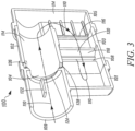
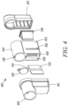
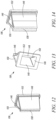
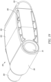
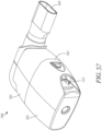
- FIGS. 1-4 a front perspective view, a rear perspective view, a cross-sectional front perspective view, and an exploded view of an OPEP device 100 are shown.
- the OPEP device 100 generally comprises a housing 102, a chamber inlet 104, a first chamber outlet 106, a second chamber outlet 108 (best seen in FIGS. 2 and 7 ), and a mouthpiece 109 in fluid communication with the chamber inlet 104. While the mouthpiece 109 is shown in FIGS.
- the mouthpiece 109 may be removable and replaceable with a mouthpiece 109 of a different size or shape, as required to maintain ideal operating conditions.
- the housing 102 and the mouthpiece 109 may be constructed of any durable material, such as a polymer.
- a polymer such as Polypropylene.
- ABS acrylonitrile butadiene styrene
- the housing 102 may include an inhalation port (not shown) having a separate one-way inhalation valve (not shown) in fluid communication with the mouthpiece 109 to permit a user of the OPEP device 100 both to inhale the surrounding air through the one-way valve, and to exhale through the chamber inlet 104 without withdrawing the mouthpiece 109 of the OPEP device 100 between periods of inhalation and exhalation.
- any number of aerosol delivery devices may be connected to the OPEP device 100, for example, through the inhalation port mentioned above, for the simultaneous administration of aerosol and OPEP therapies.
- the inhalation port may include, for example, an elastomeric adapter, or other flexible adapter, capable of accommodating the different mouthpieces or outlets of the particular aerosol delivery device that a user intends to use with the OPEP device 100.
- the housing 102 is generally box-shaped. However, a housing 102 of any shape may be used. Furthermore, the chamber inlet 104, the first chamber outlet 106, and the second chamber outlet 108 could be any shape or series of shapes, such as a plurality (i.e., more than one) of circular passages or linear slots. More importantly, it should be appreciated that the cross-sectional area of the chamber inlet 104, the first chamber outlet 106, and the second chamber outlet 108 are only a few of the factors influencing the ideal operating conditions described above.
- the exhalation flow path 110 is "folded" upon itself, i.e., it reverses longitudinal directions between the chamber inlet 104 and one of the first chamber outlet 106 or the second chamber outlet 108.
- the exhalation flow path 110 identified by the dashed line is exemplary, and that air exhaled into the OPEP device 100 may flow in any number of directions or paths as it traverses from the mouthpiece 109 or chamber inlet 104 and the first chamber outlet 106 or the second chamber outlet 108.
- FIG. 3 also shows various other features of the OPEP device 100 associated with the housing 102.
- a stop 122 prevents a restrictor member 130 (see FIG. 5 ), described below, from opening in a wrong direction;
- a seat 124 shaped to accommodate the restrictor member 130 is formed about the chamber inlet 104; and
- an upper bearing 126 and a lower bearing 128 are formed within the housing 102 and configured to accommodate a shaft rotatably mounted therebetween.
- One or more guide walls 120 are positioned in the second chamber 118 to direct exhaled air along the exhalation flow path 110.
- FIGS. 5-7 various cross-sectional perspective views of the OPEP device 100 are shown with its internal components.
- the internal components of the OPEP device 100 comprise a restrictor member 130, a vane 132, and an optional variable nozzle136.
- the restrictor member 130 and the vane 132 are operatively connected by means of a shaft 134 rotatably mounted between the upper bearing 126 and the lower bearing 128, such that the restrictor member 130 and the vane 132 are rotatable in unison about the shaft 134.
- the variable nozzle 136 includes an orifice 138 configured to increase in size in response to the flow of exhaled air therethrough.
- FIGS. 4-6 further illustrate the division of the first chamber 114 and the second chamber 118 within the housing 102.
- the chamber inlet 104 defines an entrance to the first chamber 114.
- the restrictor member 130 is positioned in the first chamber 114 relative to a seat 124 about the chamber inlet 104 such that it is moveable between a closed position, where a flow of exhaled air along the exhalation flow path 110 through the chamber inlet 104 is restricted, and an open position, where the flow of exhaled air through the chamber inlet 104 is less restricted.
- the restrictor member 130 and the vane 132 may be formed as separate components connectable by any suitable means such that they remain independently replaceable with a restrictor member 130 or a vane132 of a different shape, size, or weight, as selected to maintain ideal operating conditions.
- the restrictor member 130 and/or the vane 132 may include one or more contoured surfaces.
- the restrictor member 130 may be configured as a butterfly valve.
- variable nozzle 136 includes top and bottom walls 146, side walls 148, and V-shaped slits 150 formed therebetween.
- the variable nozzle is generally shaped like a duck-bill type valve. However, it should be appreciated that nozzles or valves of other shapes and sizes may also be used.
- the variable nozzle 136 may also include a lip 152 configured to mount the variable nozzle 136 within the housing 102 between the first chamber 114 and the second chamber 118.
- variable nozzle 136 may be constructed or molded of any material having a suitable flexibility, such as silicone, and preferably with a wall thickness of between 0.50 and 2.00 millimeters, and an orifice width between 0.25 to 1.00 millimeters, or smaller depending on manufacturing capabilities.
- variable nozzle 136 is optional in the operation of the OPEP device 100. It should also be appreciated that the OPEP device 100 could alternatively omit both the chamber passage 116 and the variable nozzle 136, and thus comprise a single-chamber embodiment. Although functional without the variable nozzle 136, the performance of the OPEP device 100 over a wider range of exhalation flow rates is improved when the OPEP device 100 is operated with the variable nozzle 136.
- the chamber passage 116 when used without the variable nozzle 136, or the orifice 138 of the variable nozzle 136, when the variable nozzle 136 is included, serves to create a jet of exhaled air having an increased velocity.
- the increased velocity of the exhaled air entering the second chamber 118 results in a proportional increase in the force applied by the exhaled air to the vane 132, and in turn, an increased torque about the shaft 134, all of which affect the ideal operating conditions.
- variable nozzle 136 Without the variable nozzle 136, the orifice between the first chamber 114 and the second chamber 118 is fixed according to the size, shape, and cross-sectional area of the chamber passage 116, which may be selectively adjusted by any suitable means, such as replacement of the middle section 103 or the rear section 105 of the housing.
- the orifice between the first chamber 114 and the second chamber 118 is defined by the size, shape, and cross-sectional area of the orifice 138 of the variable nozzle 136, which may vary according to the flow rate of exhaled air and/or the pressure in the first chamber 114.
- FIG. 14 a front perspective view of the variable nozzle 136 is shown with a flow of exhaled air therethrough.
- One aspect of the variable nozzle 136 shown in FIG. 14 is that, as the orifice 138 opens in response to the flow of exhaled air therethrough, the cross-sectional shape of the orifice 138 remains generally rectangular, which during the administration of OPEP therapy results in a lower drop in pressure through the variable nozzle 136 from the first chamber 114 ( See FIGS. 3 and 5 ) to the second chamber 118.
- the generally consistent rectangular shape of the orifice 138 of the variable nozzle 136 during increased flow rates is achieved by the V-shaped slits 150 formed between the top and bottom walls 146 and the side walls 148, which serve to permit the side walls 148 to flex without restriction.
- the V-shaped slits 150 are as thin as possible to minimize the leakage of exhaled air therethrough.
- the V-shaped slits 150 may be approximately 0.25 millimeters wide, but depending on manufacturing capabilities, could range between 0.10 and 0.50 millimeters. Exhaled air that does leak through the V-shaped slits 150 is ultimately directed along the exhalation flow path by the guide walls 120 in the second chamber 118 protruding from the housing 102.
- variable nozzle 136 has on the performance of the OPEP device 100, including the geometry and material of the variable nozzle 136.
- a target oscillating pressure frequency of between 10 to 13 Hz at an exhalation flow rate of 15 liters per minute
- a 1.0 by 20.0 millimeter passage or orifice may be utilized.
- the frequency of the oscillating pressure in that embodiment also increases, though at a rate too quickly in comparison to the target frequency.
- the same embodiment may utilize a 3.0 by 20.0 millimeter passage or orifice.
- a 3.0 by 20.0 millimeter passage or orifice Such a relationship demonstrates the desirability of a passage or orifice that expands in cross-sectional area as the exhalation flow rate increases in order to limit the drop in pressure across the variable nozzle 136.
- FIGS. 15A-C top phantom views of the OPEP device 100 show an exemplary illustration of the operation of the OPEP device 100.
- FIG. 15A shows the restrictor member 130 in an initial, or closed position, where the flow of exhaled air through the chamber inlet 104 is restricted, and the vane 132 is in a first position, directing the flow of exhaled air toward the first chamber outlet 106.
- FIG. 15B shows this restrictor member 130 in a partially open position, where the flow of exhaled air through the chamber inlet 104 is less restricted, and the vane 132 is directly aligned with the jet of exhaled air exiting the variable nozzle 136.
- FIG. 15A shows the restrictor member 130 in an initial, or closed position, where the flow of exhaled air through the chamber inlet 104 is restricted, and the vane 132 is in a first position, directing the flow of exhaled air toward the first chamber outlet 106.
- FIG. 15B shows this restrictor member 130 in a partially
- the restrictor member 130 and the vane 132 may be initially positioned as shown in FIG. 15A .
- the restrictor member 130 In this position, the restrictor member 130 is in a closed position, where the flow of exhaled air along the exhalation path through the chamber inlet 104 is substantially restricted.
- an exhalation pressure at the chamber inlet 104 begins to increase when a user exhales into the mouthpiece 108.
- a corresponding force acting on the face 140 of the restrictor member 130 increases.
- a resulting net force creates a negative or opening torque about the shaft.
- exhaled air As exhaled air continues to enter the first chamber 114 through the chamber inlet 104, it is directed along the exhalation flow path 110 by the housing 102 until it reaches the chamber passage 116 disposed between the first chamber 114 and the second chamber 118. If the OPEP device 100 is being operated without the variable nozzle 136, the exhaled air accelerates through the chamber passage 116 due to the decrease in cross-sectional area to form a jet of exhaled air.
- the exhaled air accelerates through the orifice 138 of the variable nozzle 136, where the pressure through the orifice 138 causes the side walls 148 of the variable nozzle 136 to flex outward, thereby increasing the size of the orifice 138, as well as the resulting flow of exhaled air therethrough.
- some exhaled air leaks out of the V-shaped slits 150 of the variable nozzle 136, it is directed back toward the jet of exhaled air and along the exhalation flow path by the guide walls 120 protruding into the housing 102.
- the exhaled air exits the first chamber 114 through the variable nozzle 136 and/or chamber passage 116 and enters the second chamber 118, it is directed by the vane 132 toward the front section 101 of the housing 102, where it is forced to reverse directions before exiting the OPEP device 100 through the open first chamber exit 106.
- a pressure accumulates in the second chamber 118 near the front section 101 of the housing 102, thereby resulting in a force on the adjacent vane 132, and creating an additional negative or opening torque about the shaft 134.
- the vane 132 crosses the jet of exhaled air exiting the variable nozzle 136 or the chamber passage 116.
- the jet of exhaled air exiting the variable nozzle 136 or chamber passage 116 provides a force on the vane 132 that, along with the momentum of the vane 132, the shaft 134, and the restrictor member 130, propels the vane 132 and the restrictor member 130 to the position shown in FIG. 15C .
- the force acting on the vane 132 from the exhaled air exiting the variable nozzle 136 also switches from a negative or opening torque to a positive or closing torque.
- the exhaled air exits the first chamber 114 through the variable nozzle 136 and enters the second chamber 118, it is directed by the vane 132 toward the front section 101 of the housing 102, where it is forced to reverse directions before exiting the OPEP device 100 through the open second chamber exit 108.
- a pressure accumulates in the second chamber 118 near the front section 101 of the housing 102, thereby resulting in a force on the adjacent vane 132, and creating a positive or closing torque about the shaft 134.
- the vane 132 and the restrictor member 130 continue to move closer to the position shown in FIG.
- the pressure accumulating in the section chamber 118 near the front section 101 of the housing 102, and in turn, the positive or closing torque about the shaft 134 continues to increase, as the flow of exhaled air along the exhalation flow path 110 and through the chamber inlet 104 is even less restricted.
- the torque about the shaft 134 from the force acting on the restrictor member 130 also switches from a negative or opening torque to a positive or closing torque around the position shown in FIG. 15B
- its magnitude is essentially negligible as the restrictor member 130 and the vane 132 rotate from the position shown in FIG. 15B to the position shown in FIG. 15C .
- the vane 132 and the restrictor member 130 After reaching the position shown in FIG. 15C , and due to the increased positive or closing torque about the shaft 134, the vane 132 and the restrictor member 130 reverse directions and begin to rotate back toward the position shown in FIG. 15B . As the vane 132 and the restrictor member 130 approach the position shown in FIG. 15B , and the flow of exhaled through the chamber inlet 104 is increasingly restricted, the positive or closing torque about the shaft 134 begins to decrease. When the restrictor member 130 and the vane 132 reach the position 130 shown in Fig.
- the vane 132 crosses the jet of exhaled air exiting the variable nozzle 136 or the chamber passage 116, thereby creating a force on the vane 132 that, along with the momentum of the vane 132, the shaft 134, and the restrictor member 130, propels the vane 132 and the restrictor member 130 back to the position shown in Fig. 15A .
- the flow of exhaled air through the chamber inlet 104 is restricted, and the cycle described above repeats itself.
- variable nozzle 236 may be used in the OPEP device 100 as an alternative to the variable nozzle 136 described above.
- the variable nozzle 236 includes an orifice 238, top and bottom walls 246, side walls 248, and a lip 252 configured to mount the variable nozzle 236 within the housing of the OPEP device 100 between the first chamber 114 and the second chamber 118 in the same manner as the variable nozzle 136.
- the variable nozzle 236 may be constructed or molded of any material having a suitable flexibility, such as silicone.
- positive expiratory pressure (without oscillation) may be desired, in which case the OPEP device 100 may be operated without the restrictor member 130, but with a fixed orifice or manually adjustable orifice instead.
- the positive expiratory pressure embodiment may also comprise the variable nozzle 136, or the variable nozzle 236, in order to maintain a relatively consistent back pressure within a desired range.
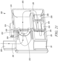
- the OPEP device 200 includes a restrictor member 230 operatively connected to a vane 232 by a pin 231, an adjustment mechanism 253, and a variable nozzle 236. As shown in the cross-sectional view of FIG. 21 , when the OPEP device 200 is in use, the variable nozzle 236 is positioned between the middle section 203 and the rear section 205 of the housing 202, and the adjustment mechanism 253, the restrictor member 230, and the vane 232 form an assembly.
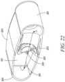
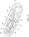
- FIGS. 21-23 various cross-sectional perspective views of the OPEP device 200 are shown.
- an exhalation flow path 210 is defined between the mouthpiece 209 and at least one of the first chamber outlet 206 and the second chamber outlet 208 (best seen in FIGS. 23 and 32 ).
- the exhalation flow path 210 begins at the mouthpiece 209 and is directed toward the chamber inlet 204, which in operation may or may not be blocked by the restrictor member 230.
- the exhalation flow path 210 After passing through the chamber inlet 204, the exhalation flow path 210 enters a first chamber 214 and makes a 180° turn toward the variable nozzle 236. After passing through the orifice 238 of the variable nozzle 236, the exhalation flow path 210 enters a second chamber 218. In the second chamber 218, the exhalation flow path 210 may exit the OPEP device 200 through at least one of the first chamber outlet 206 or the second chamber outlet 208.
- exhalation flow path 210 identified by the dashed line is exemplary, and that air exhaled into the OPEP device 200 may flow in any number of directions or paths as it traverses from the mouthpiece 209 or chamber inlet 204 to the first chamber outlet 206 or the second chamber outlet 208.
- the adjustment mechanism 253 includes an adjustment dial 254, a shaft 255, and a frame 256.
- a protrusion 258 is positioned on a rear face 260 of the adjustment dial, and is adapted to limit the selective rotation of the adjustment mechanism 253 by a user, as further described below.
- the shaft 255 includes keyed portions 262 adapted to fit within upper and lower bearings 226, 228 formed in the housing 200 (see FIGS. 21 and 28-29 ).
- the shaft further includes an axial bore 264 configured to receive the pin 231 operatively connecting the restrictor member 230 and the vane 232.
- the frame 256 is spherical, and as explained below, is configured to rotate relative to the housing 202, while forming a seal between the housing 202 and the frame 256 sufficient to permit the administration of OPEP therapy.
- the frame 256 includes a circular opening defined by a seat 224 adapted to accommodate the restrictor member 230. In use, the circular opening functions as the chamber inlet 204.
- the frame 256 also includes a stop 222 for preventing the restrictor member 230 from opening in a wrong direction.
- FIG. 26 a front perspective view of the restrictor member 230 and the vane 232 is shown.
- the design, materials, and configuration of the restrictor member 230 and the vane 232 may be the same as described above in regards to the OPEP device 100.
- the restrictor member 230 and the vane 232 in the OPEP device 200 are operatively connected by a pin 231 adapted for insertion through the axial bore 264 in the shaft 255 of the adjustment mechanism 253.
- the pin 231 may be constructed, for example, by stainless steel. In this way, rotation of the restrictor member 230 results in a corresponding rotation of the vane 232, and vice versa.
- FIG. 27 a front perspective view of the adjustment mechanism 253 assembled with the restrictor member 230 and the vane 232 is shown.
- the restrictor member 230 is positioned such that it is rotatable relative to the frame 256 and the seat 224 between a closed position (as shown), where a flow of exhaled air along the exhalation flow path 210 through the chamber inlet 204 is restricted, and an open position (not shown), where the flow of exhaled air through the chamber inlet 204 is less restricted.
- the vane 232 is operatively connected to the restrictor member 230 by the pin 231 extending through shaft 255, and is adapted to move in unison with the restrictor member 230.
- the restrictor member 230 and the vane 232 are supported by the adjustment mechanism 253, which itself is rotatable within the housing 202 of the OPEP device 200, as explained below.
- FIGS. 28 and 29A-B are partial cross-sectional views illustrating the adjustment mechanism 253 mounted within the housing 202 of the OPEP device 200.
- the adjustment mechanism 253, as well as the restrictor member 230 and the vane 232 are rotatably mounted within the housing 200 about an upper and lower bearing 226, 228, such that a user is able to rotate the adjustment mechanism 253 using the adjustment dial 254.
- FIGS 29A-29B further illustrates the process of mounting and locking the adjustment mechanism 253 within the lower bearing 228 of the housing 202. More specifically, the keyed portion 262 of the shaft 255 is aligned with and inserted through a rotational lock 166 formed in the housing 202, as shown in FIG. 29A .
- the shaft 255 is rotated 90° to a locked position, but remains free to rotate.
- the adjustment mechanism 253 is mounted and locked within the upper bearing 226 in the same manner.
- the rotation of the shaft 255 is restricted to keep it within a locked position in the rotational lock 166.
- two stops 268, 288 are positioned on the housing 202 such that they engage the protrusion 258 formed on the rear face 260 of the adjustment dial 254 when a user rotates the adjustment dial 254 to a predetermined position.
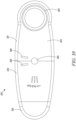
- the OPEP device 200 is shown in FIG. 30 without the adjustment dial 254 or the adjustment mechanism 253, which would extend from the housing 202 through an opening 269. In this way, rotation of the adjustment dial 254, the adjustment mechanism 253, and the keyed portion 262 of the shaft 255 can be appropriately restricted.
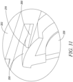
- FIG. 31 a partial cross-sectional view of the adjustment mechanism 253 mounted within the housing 200 is shown.
- the frame 256 of the adjustment mechanism 253 is spherical, and is configured to rotate relative to the housing 202, while forming a seal between the housing 202 and the frame 256 sufficient to permit the administration of OPEP therapy.
- a flexible cylinder 271 extending from the housing 202 completely surrounds a portion of the frame 256 to form a sealing edge 270.
- the flexible cylinder 271 and the frame 256 may be constructed of a low shrink, low friction plastic. One such material is acetal. In this way, the sealing edge 270 contacts the frame 256 for a full 360° and forms a seal throughout the permissible rotation of the adjustment member 253.
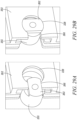
- FIGS. 32A-B are partial cross-sectional views of the OPEP device 200;
- FIGS. 33A-B are illustrations of the adjustability of the OPEP device 200; and
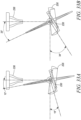
- FIGS. 34A-B are top phantom views of the OPEP device 200.
- the vane 232 and the restrictor member 230 are configured such that when the OPEP device 200 is fully assembled, the angle between a centerline of the variable nozzle 236 and the vane 232 is between 10° and 25° when the restrictor member 230 is in a closed position.
- the adjustability of the OPEP device 200 is not limited to the parameters described herein, and that any number of configurations may be selected for purposes of administering OPEP therapy within the ideal operating conditions.
- FIG. 32A shows the vane 232 at an angle of 10° from the centerline of the variable nozzle 236, whereas FIG. 32B shows the vane 232 at an angle of 25° from the centerline of the variable nozzle 236.
- FIG. 33A illustrates the necessary position of the frame 256 (shown in phantom) relative to the variable nozzle 236 such that the angle between a centerline of the variable nozzle 236 and the vane 232 is 10° when the restrictor member 230 is in the closed position.
- FIG. 33A illustrates the necessary position of the frame 256 (shown in phantom) relative to the variable nozzle 236 such that the angle between a centerline of the variable nozzle 236 and the vane 232 is 10° when the restrictor member 230 is in the closed position.
- 33B illustrates the necessary position of the frame 256 (shown in phantom) relative to the variable nozzle 236 such that the angle between a centerline of the variable nozzle 236 and the vane 232 is 25° when the restrictor member 230 is in the closed position.
- FIGS 34A-B side phantom views of the OPEP device 200 are shown.
- the configuration shown in FIG. 34A corresponds to the illustrations shown in FIGS 32A and 33A , wherein the angle between a centerline of the variable nozzle 236 and the vane 232 is 10° when the restrictor member 230 is in the closed position.
- FIG. 34B corresponds to the illustrations shown in FIGS. 32B and 33B , wherein the angle between a centerline of the variable nozzle 236 and the vane 232 is 25° when the restrictor member 230 is in the closed position.
- the frame 256 of the adjustment member 253 has been rotated counter-clockwise 15°, from the position shown in FIG. 34A , to the position shown in FIG. 34B , thereby also increasing the permissible rotation of the vane 232.
- a user is able to rotate the adjustment dial 254 to selectively adjust the orientation of the chamber inlet 204 relative to the restrictor member 230 and the housing 202.
- a user may increase the frequency and amplitude of the OPEP therapy administered by the OPEP device 200 by rotating the adjustment dial 254, and therefore the frame 256, toward the position shown in FIG. 34A .
- a user may decrease the frequency and amplitude of the OPEP therapy administered by the OPEP device 200 by rotating the adjustment dial 254, and therefore the frame 256, toward the position shown in FIG. 34B .
- indicia may be provided to aid the user in the setting of the appropriate configuration of the OPEP device 200.
- the reset button 545' may also be rotated relative to the housing 561' in order to selectively adjust a position of the valve brace 511' relative to the valve 509', thereby selectively increasing or decreasing the threshold exhalation pressure at which the Huff Cough mechanism 553' opens.
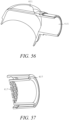
- the mouthpiece 551' may serve as the valve 557. That is the mouthpiece 551' may be shaped and sized to fit in sliding engagement within the housing 561', such that a user may selectively move the mouthpiece 551' between open and closed positions (e.g. by sliding into and out of the housing 561', as shown in FIGS. 71B and 72B , or by rotation of an opening in the mouthpiece 551' relative to the conduit segment leading to the OPEP mechanism). In FIG. 71B , the mouthpiece 551' is in an open position, such that exhaled air is free to flow from the mouthpiece 551' into the OPEP mechanism for the administration of OPEP therapy.
- valve 509' of the Huff Cough mechanism 553' blows open, thereby allowing the flow of air through the Huff Cough mechanism 553'.
- the valve 509' may be reset to the closed position by pressing the reset button 545' and extending the rod 549', for performing subsequent Huff Cough simulations.
- the valve 657 is closed, such that exhaled air is blocked from flowing past the valve 657 into the OPEP mechanism 655, forcing the exhaled air into the Huff cough mechanism 653 for simulating a Huff Cough (without OPEP).
- the inhalation valve 663 is configured to remain closed during a period of exhalation, opening only during a period of inhalation. In this configuration, as air is exhaled by a user into the mouthpiece 651, pressure increases within the conduit 659 and the Huff Cough mechanism 653, until a threshold pressure is reached, at which point a valve or blocking member within the Huff Cough mechanism 653 opens, thereby allowing the flow of air through the Huff Cough mechanism 653.
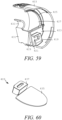
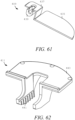
- the Huff Cough mechanism 653' includes a reset finger 649' extending from the housing 661' toward the valve 609'.
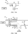
- the mouthpiece 651' may be shaped and sized to fit in sliding engagement within the housing 661' or a portion of the housing, such that a user may selectively move the mouthpiece 651' between a first position (shown in FIG. 73B ), where the valve 609' is opened by the finger 649', and a second position (shown in FIG. 74B ), where the finger 649' is retracted and the valve 609' is closed.
- the mouthpiece 651' may be biased toward the second position (shown in FIG.
- the valve 609' when the valve 609' is in an open position, as illustrated by the dashed line in FIG 74B , a user may selectively move the mouthpiece 651' relative to the housing 661' from the second position (shown in FIG. 74B ) to the first position (shown in FIG. 73B ), thereby moving the valve 609' to the position illustrated by the dashed line in FIG. 73B .
- the valve 609' returns to a closed position (shown in FIG. 74B ), for performing another Huff Cough simulation.
- the inhalation valve 663'and the valve 609' of the Huff Cough mechanism 653' are configured to open upon inhalation at the mouthpiece.
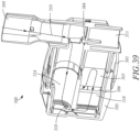
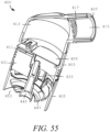
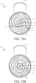
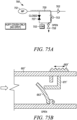
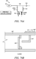
- FIGS. 75A , 76A , and 77 are schematics illustrating the primary components of a combined OPEP and Huff Cough simulation device 700.
- FIGS. 75B and 76B are partial cross-sectional views illustrating modifications to the combined OPEP and Huff Cough simulation device 600' shown and described with reference to FIGS. 73B and 74B , showing selective opening and closing of the inhalation valve 663'.
- the device 700 is configured to selectively provide Huff Cough simulations without OPEP therapy (illustrated in FIGS. 75A and 75B ), OPEP therapy without any Huff Cough simulation (illustrated in FIGS. 76A and 76B ), or a Huff Cough simulation followed by OPEP therapy (illustrated in FIGS. 77 and 76B ).
- the OPEP mechanism 755 may comprise any suitable OPEP device, including any of the previously described or identified OPEP devices.
- the Huff Cough mechanism 753 may comprise any suitable Huff Cough simulation device, including any of the previously described or identified Huff Cough simulation devices.
- the first valve 757 and the second valve 758 may comprise any suitable means for selectively opening and closing the flow of air through the conduit segments having the valves 757 and 758, including for example, a gate valve, a ball valve, or a butterfly valve.
- the valves 757 and 758 may be selectively opened and closed by the user, for example, via a thumb screw, a lever, a switch, or the like.
- a suitable inhalation vale 763 for example, is shown and described with reference to FIG. 52 .
- the first valve 757 may be achieved by selectively opening and closing the valve or blocking member of the Huff Cough mechanism 753, as shown and described above with regard to FIGS. 73B and 74B .
- the second valve 758 may alternatively be achieved by selectively opening and closing the inhalation valve 763, as shown and described below with regard to FIGS. 75B and 76B .
- the first valve 757 is closed, such that exhaled air is blocked from flowing past the first valve 757 into the OPEP mechanism 755, forcing the exhaled air into the Huff Cough mechanism 753 for simulating a Huff Cough (without OPEP).
- the inhalation valve 763 is configured to remain closed during a period of exhalation, opening only during a period of inhalation. In this configuration, as air is exhaled by a user into the mouthpiece 751, pressure increases within the conduit 759 and the Huff Cough mechanism 753, until a threshold pressure is reached, at which point a valve or blocking member within the Huff Cough mechanism 753 opens, thereby allowing the flow of air through the Huff Cough mechanism 753.
- the second valve 758 is open, such that air flowing through the Huff Cough mechanism 753 is free to flow past the second valve 758 and exit the device 700, rather than into the OPEP mechanism 755.
- FIGS. 75B and 76B are partial cross-sectional views illustrating modifications to the combined OPEP and Huff Cough simulation device 600' shown and described with reference to FIGS. 73B and 74B . That is, an exemplary device according to the configuration of FIGS. 75A , 76A , and 77 may include the combined OPEP and Huff Cough simulation device 600', modified as described below with reference to FIGS. 75B and 76B .
- the second valve 758 may be achieved by selectively opening and closing the inhalation valve 763.
- a switch 669' located on the outside of the housing 661' may be positioned relative to the inhalation valve 663' such that a finger 671' extending from the switch 669' toward the inhalation valve 663' may be selectively moved between a first position (shown in FIG. 75B ), where the finger 671' holds the inhalation valve 663' in an open position, and a second position (shown in FIG. 76B ), where the finger 671' is retracted from the inhalation valve 663', allowing the inhalation valve 663' to remain closed, opening only during a period of inhalation.
- the device 600' may be used to simulate a Huff Cough (without OPEP therapy) by selectively positioning the mouthpiece 651' in the second position (illustrated in FIG. 74B ), while the switch 669' is positioned in the first position (illustrated in FIG. 75B ).
- the device 600' may be used to administer OPEP therapy (without Huff Cough) by selectively positioning the mouthpiece 651' in the first position (illustrated in FIG. 73B ), while the switch 669' is positioned in the second position (illustrated in FIG. 76B ).
- the device 600' may be used to simulate a Huff Cough followed by administration of OPEP therapy, by selectively positioning the mouthpiece 651' in the second position (illustrated in FIG. 74B ), while the switch 669' is positioned in the second position (illustrated in FIG. 76B ).
Landscapes
- Health & Medical Sciences (AREA)
- Pulmonology (AREA)
- General Health & Medical Sciences (AREA)
- Life Sciences & Earth Sciences (AREA)
- Emergency Medicine (AREA)
- Biomedical Technology (AREA)
- Heart & Thoracic Surgery (AREA)
- Hematology (AREA)
- Engineering & Computer Science (AREA)
- Animal Behavior & Ethology (AREA)
- Anesthesiology (AREA)
- Public Health (AREA)
- Veterinary Medicine (AREA)
- Physical Education & Sports Medicine (AREA)
- Measurement Of The Respiration, Hearing Ability, Form, And Blood Characteristics Of Living Organisms (AREA)
- Respiratory Apparatuses And Protective Means (AREA)
- Percussion Or Vibration Massage (AREA)
Claims (14)
- Dispositif de thérapie respiratoire (500, 500', 600, 600', 700) comprenant : un mécanisme OPEP (pression expiratoire positive oscillante) (555, 555', 655, 655', 755) ayant un élément restricteur mobile de manière répétée en réponse à un flux d'air entre une position fermée où le flux d'air à travers le mécanisme OPEP (555, 555', 655, 655', 755) est restreint, et une position ouverte où le flux d'air à travers le mécanisme OPEP (555, 555', 655, 655', 755) est moins restreint ;un mécanisme de toux soufflée (Huff Cough) (553, 553', 653, 653', 753) ayant une valve (509') mobile en réponse à une pression d'expiration seuil depuis une position fermée où un flux d'air à travers le mécanisme de toux soufflée (553, 553', 653, 653', 753) est restreint, vers une position ouverte où un flux d'air à travers le mécanisme de toux soufflée (553, 553', 653, 653', 753) est moins restreintune interface utilisateur (551, 551', 651, 651', 751) ;un conduit (559) menant de l'interface utilisateur au mécanisme OPEP (555, 555', 655, 655', 755) et au mécanisme de toux soufflée (553, 553', 653, 653', 753), et dans lequel un flux d'air à travers le conduit (559) est dirigé sélectivement vers le mécanisme OPEP (555, 555', 655, 655', 755), le mécanisme de toux soufflée, ou à la fois le mécanisme OPEP (555, 555', 655, 655', 755) et le mécanisme de toux soufflée.
- Dispositif de thérapie respiratoire selon la revendication 1, dans lequel un flux d'air à travers le conduit (559) passe à travers le mécanisme de toux soufflée, suivi du mécanisme OPEP (555, 555', 655, 655').
- Dispositif de thérapie respiratoire selon la revendication 1, comprenant en outre une valve (557, 657, 757) positionnée dans le conduit pour diriger sélectivement un flux d'air vers le mécanisme OPEP (555, 555', 655, 655', 755) et le mécanisme de toux soufflée.
- Dispositif de thérapie respiratoire selon la revendication 1, dans lequel le mécanisme OPEP (555, 555', 655, 655') est positionné le long d'un premier segment du conduit (559) et le mécanisme de toux soufflée est positionné le long d'un second segment du conduit (559), où un flux d'air à travers le premier segment ne traverse pas le second segment, et un flux d'air à travers le second segment ne traverse pas le premier segment.
- Dispositif de thérapie respiratoire selon la revendication 4, comprenant en outre une valve (657) positionnée dans le premier segment, dans lequel la valve (657) est sélectivement mobile entre une position ouverte où un flux d'air à travers le premier segment vers le mécanisme OPEP (655, 655') est permis, et une position fermée où un flux d'air à travers le premier segment vers le mécanisme OPEP (655, 655') n'est pas permis, et
dans lequel la valve (657) est sélectivement mobile entre la position ouverte pour fournir une thérapie OPEP, et la position fermée pour fournir une simulation de toux soufflée. - Dispositif de thérapie respiratoire selon la revendication 1, dans lequel la valve du mécanisme de toux soufflée est configurée pour s'ouvrir en réponse à l'inspiration au niveau de l'interface utilisateur (551, 551', 651, 651').
- Dispositif de thérapie respiratoire selon la revendication 1, dans lequel l'interface utilisateur (551, 551') est mobile par rapport au conduit (559) entre une première position, où le flux d'air à travers le conduit (559) vers le mécanisme OPEP (555, 555', 655, 655') est permis, et une seconde position où le flux d'air vers le mécanisme OPEP (555, 555', 655, 655') n'est pas permis.
- Dispositif de thérapie respiratoire selon la revendication 3, dans lequel la valve (757) est positionnée le long d'un premier segment du conduit (759) et le mécanisme de toux soufflée (753) est positionné le long d'un second segment du conduit (759), où le flux d'air le long du premier segment ne traverse pas le second segment, et le flux d'air le long du second segment ne traverse pas le premier segment.
- Dispositif de thérapie respiratoire selon la revendication 1, dans lequel le mécanisme de toux soufflée (653, 653') et un doigt (649') à l'intérieur du dispositif sont sélectivement mobiles l'un par rapport à l'autre pour ouvrir la valve du mécanisme de toux soufflée (653, 653').
- Dispositif de thérapie respiratoire (700) selon la revendication 8, dans lequel le mécanisme OPEP (755) est positionné le long d'un troisième segment du conduit (759) où le premier segment et le second segment sont joints, et une seconde valve (758) est positionnée le long d'un quatrième segment du conduit (759) où le premier segment et le second segment sont joints, où un flux d'air le long du troisième segment ne traverse pas le quatrième segment, et un flux d'air le long du quatrième segment ne traverse pas le troisième segment.
- Dispositif de thérapie respiratoire (700) selon la revendication 10, dans lequel la valve (757) est sélectivement mobile entre une position ouverte où un flux d'air le long du premier segment est permis, et une position fermée où un flux d'air le long du premier segment n'est pas permis, et dans lequel la seconde valve (758) est sélectivement mobile entre une position ouverte où un flux d'air le long du quatrième segment est permis, et une position fermée où un flux d'air le long du quatrième segment n'est pas permis.
- Dispositif de thérapie respiratoire (700) selon la revendication 11, dans lequel le dispositif est configuré pour fournir une simulation de toux soufflée sans thérapie OPEP lorsque la valve (757) se trouve dans la position fermée et que la seconde valve (758) se trouve dans la position ouverte, ou
le dispositif est configuré pour fournir une thérapie OPEP sans quelconque simulation de toux soufflée lorsque la valve (757) se trouve dans la position ouverte et que la seconde valve (758) se trouve dans la position fermée. - Dispositif de thérapie respiratoire selon la revendication 11, dans lequel le dispositif est configuré pour fournir une simulation de toux soufflée suivie d'une thérapie OPEP lorsque la valve (757) se trouve dans la position fermée et que la seconde valve (758) se trouve dans la position fermée.
- Dispositif de thérapie respiratoire selon la revendication 1, comprenant en outre une valve d'inspiration (663, 663') positionnée le long du conduit (759),
dans lequel un flux d'air entre la valve d'inspiration (663, 663') et l'interface utilisateur (651, 651') ne passe pas à travers le mécanisme OPEP (655, 655') ou le mécanisme de toux soufflée (653, 653').
Applications Claiming Priority (2)
| Application Number | Priority Date | Filing Date | Title |
|---|---|---|---|
| US201762500707P | 2017-05-03 | 2017-05-03 | |
| PCT/IB2018/052899 WO2018203188A1 (fr) | 2017-05-03 | 2018-04-26 | Thérapie par pression expiratoire positive oscillante combinée et dispositif de simulation de toux soufflée ("huff cough") |
Publications (4)
| Publication Number | Publication Date |
|---|---|
| EP3618908A1 EP3618908A1 (fr) | 2020-03-11 |
| EP3618908A4 EP3618908A4 (fr) | 2021-01-13 |
| EP3618908B1 true EP3618908B1 (fr) | 2025-03-26 |
| EP3618908C0 EP3618908C0 (fr) | 2025-03-26 |
Family
ID=64016962
Family Applications (1)
| Application Number | Title | Priority Date | Filing Date |
|---|---|---|---|
| EP18795069.6A Active EP3618908B1 (fr) | 2017-05-03 | 2018-04-26 | Thérapie par pression expiratoire positive oscillante combinée et dispositif de simulation de toux soufflée ("huff cough") |
Country Status (5)
| Country | Link |
|---|---|
| US (1) | US11559723B2 (fr) |
| EP (1) | EP3618908B1 (fr) |
| CA (2) | CA3059532C (fr) |
| ES (1) | ES3022838T3 (fr) |
| WO (1) | WO2018203188A1 (fr) |
Families Citing this family (6)
| Publication number | Priority date | Publication date | Assignee | Title |
|---|---|---|---|---|
| CN109152891B (zh) * | 2016-03-24 | 2022-11-08 | 特鲁德尔医学国际公司 | 具有电子指示器的呼吸护理系统 |
| CN113164703A (zh) * | 2018-11-27 | 2021-07-23 | 皇家飞利浦有限公司 | 在主动和非侵入式通气模式之间转换回路的模块化呼气装置 |
| US11813397B2 (en) | 2019-06-11 | 2023-11-14 | Justin Rowley | Nebulizer with flutter valve |
| WO2022003193A1 (fr) * | 2020-07-02 | 2022-01-06 | Bathysmed | Dispositif de ventilation, systeme incluant le dispositif de ventilation, et utilisations de ceux-ci |
| CN114452592B (zh) * | 2022-03-09 | 2022-10-28 | 青岛大学附属医院 | 一种呼吸内科肺功能康复理疗装置 |
| TWI795294B (zh) * | 2022-05-19 | 2023-03-01 | 貝斯美德股份有限公司 | 易於拆卸組裝及清潔的吐氣正壓震盪裝置 |
Family Cites Families (181)
| Publication number | Priority date | Publication date | Assignee | Title |
|---|---|---|---|---|
| US393869A (en) | 1888-12-04 | Inhaler | ||
| US938808A (en) | 1909-05-03 | 1909-11-02 | Silas T Yount | Therapeutic device. |
| US2670739A (en) | 1951-07-02 | 1954-03-02 | Charles M Mcneill | Inhaler |
| US2918917A (en) | 1955-03-02 | 1959-12-29 | John H Emerson | Apparatus for vibrating portions of a patient's airway |
| US3486502A (en) | 1966-09-09 | 1969-12-30 | Dynasciences Corp | Positive pressure flow cut-off respiration system |
| US3710780A (en) | 1971-08-05 | 1973-01-16 | R Milch | Respiratory device with variable expiratory pressure resistance |
| US3908987A (en) | 1973-09-27 | 1975-09-30 | John R Boehringer | Controlled positive end pressure expiratory device |
| US4054134A (en) | 1975-09-15 | 1977-10-18 | Kritzer Richard W | Respirators |
| US4182366A (en) | 1976-01-08 | 1980-01-08 | Boehringer John R | Positive end expiratory pressure device |
| US4062358A (en) | 1976-04-21 | 1977-12-13 | Kritzer Richard W | Respirators |
| US4231375A (en) | 1977-10-20 | 1980-11-04 | Boehringer John R | Pulmonary exerciser |
| FI56120C (fi) | 1978-04-18 | 1979-12-10 | Taisto Haekkinen | Ventil avsedd foer respirator eller foer annan upplivningsanvaendning laempad anordning |
| US4210174A (en) | 1978-05-30 | 1980-07-01 | Instrumentation Industries, Inc. | Positive pressure valves |
| US4198969A (en) | 1978-10-06 | 1980-04-22 | Baxter Travenol Laboratories, Inc. | Suction-operated nebulizer |
| US4226233A (en) | 1978-10-10 | 1980-10-07 | Longevity Products, Inc. | Respirators |
| US4221381A (en) | 1978-12-26 | 1980-09-09 | Albany International Corp. | Respiratory exerciser |
| US4436090A (en) | 1979-01-22 | 1984-03-13 | Darling Phillip H | Piston actuated, pilot valve operated breathing regulator |
| US4275722A (en) | 1979-05-04 | 1981-06-30 | Sorensen Harry D | Respiratory exerciser and rebreathing device |
| US4327740A (en) | 1979-11-19 | 1982-05-04 | Clyde Shuman | Incentive spirometer |
| US4298023A (en) | 1980-09-09 | 1981-11-03 | Mcginnis Gerald E | Spring loaded exhalation valve |
| US4473082A (en) | 1980-10-20 | 1984-09-25 | Gereg Gordon A | Lung exerciser with variable resistance |
| US5862802A (en) | 1981-04-03 | 1999-01-26 | Forrest M. Bird | Ventilator having an oscillatory inspiratory phase and method |
| US4403616A (en) | 1981-06-09 | 1983-09-13 | K-Med, Inc. | Expiratory breathing exercise device |
| US4487207A (en) | 1981-10-15 | 1984-12-11 | Edward Fitz | Lung exercising device and method |
| US4533137A (en) | 1982-01-19 | 1985-08-06 | Healthscan Inc. | Pulmonary training method |
| US4470412A (en) | 1982-03-19 | 1984-09-11 | Trutek Research, Inc. | Inhalation valve |
| JPS6099268A (ja) | 1983-11-04 | 1985-06-03 | シャープ株式会社 | コンスタントフロ−制御方式 |
| US4601465A (en) | 1984-03-22 | 1986-07-22 | Roy Jean Yves | Device for stimulating the human respiratory system |
| US4611591A (en) | 1984-07-10 | 1986-09-16 | Sharp Kabushiki Kaisha | Expiration valve control for automatic respirator |
| US4651731A (en) | 1984-09-17 | 1987-03-24 | Figgie International Inc. | Self-contained portable single patient ventilator/resuscitator |
| US4739987A (en) | 1985-10-28 | 1988-04-26 | Nicholson Marguerite K | Respiratory exerciser |
| US4770413A (en) | 1987-04-27 | 1988-09-13 | Mba Healthcare Products, Inc. | Breathing exercise device |
| US4981295A (en) | 1987-05-11 | 1991-01-01 | City Of Hope | Respiratory training using feedback |
| AU607164B2 (en) | 1987-10-22 | 1991-02-28 | Varioraw Percutive S.A. | Expiration resistance apparatus for improving the pulmonary ventilation |
| US4854574A (en) | 1988-03-15 | 1989-08-08 | 501 Healthscan, Inc. | Inspirator muscle trainer |
| US4951661A (en) | 1988-06-08 | 1990-08-28 | Thayer Medical Corporation | Quick-connect adapter valve for connecting nebulizer and fluid ventilator hose |
| DE3822949A1 (de) | 1988-07-07 | 1990-01-11 | Draegerwerk Ag | Pneumatisches steuerventil |
| EP0372148A1 (fr) | 1988-12-09 | 1990-06-13 | Erik Folke Norell | Dispositif pour exercices respiratoires |
| BE1004384A3 (nl) | 1989-08-03 | 1992-11-10 | Labaere Emmanuel | Toestel voor het toepassen van in- en uitademingstechnieken. |
| US5042467A (en) | 1990-03-28 | 1991-08-27 | Trudell Medical | Medication inhaler with fitting having a sonic signalling device |
| DE4022393A1 (de) | 1990-07-13 | 1992-01-23 | Marquardt Klaus | Ionisator zur ionisierung von sauerstoff bei sauerstoff-therapie |
| US5190036A (en) | 1991-02-28 | 1993-03-02 | Linder Steven H | Abdominal binder for effectuating cough stimulation |
| US6119688A (en) | 1991-08-26 | 2000-09-19 | 3M Innovative Properties Company | Powder dispenser |
| US5345930A (en) | 1992-02-10 | 1994-09-13 | National Research Council Canada Intellectual Property Services Office | Method and apparatus for assisting expulsional movement of pulmonary secretions via supramaximal flows |
| US5397337A (en) | 1992-04-02 | 1995-03-14 | Illinois Institute Of Technology | Method and apparatus for artificially stimulating cough reflex |
| CH685475A5 (fr) | 1992-04-10 | 1995-07-31 | Varioraw Percutive Sa | Appareil thérapeutique spécifique du domaine respiratoire. |
| US5647345A (en) | 1992-05-12 | 1997-07-15 | Saul; Gilbert D. | Respiratory stimulator & methods of use |
| NZ250105A (en) | 1992-11-09 | 1996-07-26 | Monaghan Canadian Ltd | Inhalator mask; one-way valve opens upon exhalation |
| US5372128A (en) | 1993-04-14 | 1994-12-13 | Habley Medical Technology Corporation | Fluidizing powder inhaler |
| DE69413989T2 (de) | 1993-08-18 | 1999-04-08 | Fisons Plc, Ipswich, Suffolk | Inhalator mit atemstromregelung |
| US5655520A (en) | 1993-08-23 | 1997-08-12 | Howe; Harvey James | Flexible valve for administering constant flow rates of medicine from a nebulizer |
| US6604523B2 (en) | 1993-11-09 | 2003-08-12 | Cprx Llc | Apparatus and methods for enhancing cardiopulmonary blood flow and ventilation |
| US5570682A (en) | 1993-12-14 | 1996-11-05 | Ethex International, Inc. | Passive inspiratory nebulizer system |
| US5479920A (en) | 1994-03-01 | 1996-01-02 | Vortran Medical Technology, Inc. | Breath actuated medicinal aerosol delivery apparatus |
| US5598839A (en) | 1994-04-20 | 1997-02-04 | Diemolding Corporation | Positive expiratory pressure device |
| DE4416575A1 (de) | 1994-05-11 | 1995-11-16 | Ulrich H Prof Dr Med Cegla | Therapiegerät |
| US5848588A (en) | 1994-05-25 | 1998-12-15 | Trudell Medical Group | Backpiece for receiving an MDI adapter in an aerosolization spacer |
| GB9410935D0 (en) | 1994-06-01 | 1994-07-20 | Dranez Anstalt | Ventilator apparatus |
| US5613489A (en) | 1994-12-07 | 1997-03-25 | Westmed, Inc. | Patient respiratory system drug applicator |
| US5540220A (en) | 1994-12-08 | 1996-07-30 | Bear Medical Systems, Inc. | Pressure-limited, time-cycled pulmonary ventilation with volume-cycle override |
| US6083141A (en) | 1995-02-10 | 2000-07-04 | Hougen; Everett D. | Portable respiratory exercise apparatus and method for using the same |
| CA2212642C (fr) | 1995-02-10 | 2009-05-05 | Everett D. Hougen | Appareil respiratoire individuel et portable |
| US5658221A (en) | 1995-02-10 | 1997-08-19 | Hougen; Everett D. | Portable personal breathing apparatus and method of using same |
| DE29506633U1 (de) * | 1995-04-19 | 1995-06-22 | Bachmann, Walter, Dr.med., 66538 Neunkirchen | Atemtraininggerät für COPD - Patienten |
| FR2733917B1 (fr) | 1995-05-12 | 1997-10-17 | Benarrouch Jacques | Variateur oscillatoire de pression pour reduire la viscosite des mucus thixotropes pour leur expectoration des poumons et des bronches |
| EP0862474A4 (fr) | 1995-09-18 | 2000-05-03 | Resmed Ltd | Regulation de la pression pour ventilation spontanee en pression positive continue ou respiration assistee |
| US5899832A (en) | 1996-06-14 | 1999-05-04 | Hougen; Everett D. | Compact lung exercising device |
| US5896857A (en) | 1996-12-20 | 1999-04-27 | Resmed Limited | Valve for use in a gas delivery system |
| US5857957A (en) | 1997-03-04 | 1999-01-12 | Lin; Vernon Wen-Hau | Functional magentic stimulation of the expiratory muscles |
| US5791339A (en) | 1997-03-13 | 1998-08-11 | Nellcor Puritan Bennettt Incorprated | Spring piloted safety valve with jet venturi bias |
| US5829429A (en) | 1997-04-21 | 1998-11-03 | Hughes; Arthur R. | Acoustic respiratory therapy apparatus |
| US6058932A (en) | 1997-04-21 | 2000-05-09 | Hughes; Arthur R. | Acoustic transceiver respiratory therapy apparatus |
| GB9709275D0 (en) | 1997-05-07 | 1997-06-25 | Hayek Zamir | Fluid control valve and oscillator for producing a pressure waveform |
| DE19720701A1 (de) | 1997-05-16 | 1998-11-19 | Gsf Forschungszentrum Umwelt | Vorrichtung zur Applikation eines Medikament-Aerosols über die Lunge |
| US6044841A (en) | 1997-08-29 | 2000-04-04 | 1263152 Ontario Inc. | Breath actuated nebulizer with valve assembly having a relief piston |
| US6293279B1 (en) | 1997-09-26 | 2001-09-25 | Trudell Medical International | Aerosol medication delivery apparatus and system |
| US6345617B1 (en) | 1997-09-26 | 2002-02-12 | 1263152 Ontario Inc. | Aerosol medication delivery apparatus and system |
| US6067984A (en) | 1997-10-14 | 2000-05-30 | Piper; Samuel David | Pulmonary modulator apparatus |
| US5925831A (en) | 1997-10-18 | 1999-07-20 | Cardiopulmonary Technologies, Inc. | Respiratory air flow sensor |
| US6026807A (en) | 1998-02-27 | 2000-02-22 | Diemolding Corporation | Metered dose inhaler cloud chamber |
| US6066101A (en) | 1998-04-20 | 2000-05-23 | University Of Maryland | Airflow perturbation device and method for measuring respiratory resistance |
| US6102038A (en) | 1998-05-15 | 2000-08-15 | Pulmonetic Systems, Inc. | Exhalation valve for mechanical ventilator |
| JP3768689B2 (ja) | 1998-07-31 | 2006-04-19 | スズキ株式会社 | 人工呼吸器 |
| AUPP512398A0 (en) | 1998-08-07 | 1998-09-03 | Resmed Limited | A control member for a valve and method for determining fluid flow rate through a valve |
| WO2000027455A1 (fr) | 1998-11-06 | 2000-05-18 | Salter Labs | Embout buccal et accessoires pour nebuliseur |
| WO2000038848A1 (fr) | 1998-12-25 | 2000-07-06 | Kyowa Hakko Kogyo Co., Ltd. | Generateur d'ondes stationnaires de gaz |
| DK1196211T3 (da) | 1999-05-28 | 2006-01-02 | Integrated Biosystems | Forbedret optöning af biofarmaceutiske oplösninger ved anvendelse af en oscillatorisk bevægelse |
| AU766506B2 (en) | 1999-06-18 | 2003-10-16 | Powerlung Inc | Pulmonary exercise device |
| US6615831B1 (en) | 1999-07-02 | 2003-09-09 | Respironics, Inc. | Pressure support system and method and a pressure control valve for use in such system and method |
| US6253766B1 (en) | 1999-08-24 | 2001-07-03 | Dhd Healthcare Corporation | Continuous positive airway pressure therapy device |
| US6708690B1 (en) | 1999-09-03 | 2004-03-23 | Respironics, Inc. | Apparatus and method for providing high frequency variable pressure to a patient |
| US6581596B1 (en) | 1999-09-24 | 2003-06-24 | Respironics, Inc. | Apparatus and method of providing high frequency variable pressure to a patient |
| US6340025B1 (en) | 1999-10-04 | 2002-01-22 | American Biosystems, Inc. | Airway treatment apparatus with airflow enhancement |
| SE9903990D0 (sv) | 1999-11-02 | 1999-11-02 | Shl Medical Ab | Inhalator with aerosolizing unit |
| USD440651S1 (en) | 1999-11-24 | 2001-04-17 | Dhd Healthcare Corporation | Positive expiratory pressure device |
| US6776159B2 (en) | 1999-11-24 | 2004-08-17 | Dhd Healthcare Corporation | Positive expiratory pressure device with bypass |
| US6581598B1 (en) | 1999-11-24 | 2003-06-24 | Dhd Healthcare Corporation | Positive expiratory pressure device |
| US7059324B2 (en) | 1999-11-24 | 2006-06-13 | Smiths Medical Asd, Inc. | Positive expiratory pressure device with bypass |
| US6240917B1 (en) | 1999-12-20 | 2001-06-05 | Joseph R. Andrade | Aerosol holding chamber for a metered-dose inhaler |
| US6369725B1 (en) | 2000-09-26 | 2002-04-09 | International Business Machines Corporation | Method for binary to decimal conversion |
| US6412481B1 (en) | 1999-12-23 | 2002-07-02 | Robert Bienvenu | Sealed backpressure attachment device for nebulizer |
| US6447459B1 (en) | 2000-04-07 | 2002-09-10 | Pds Healthcare Products, Inc. | Device and method for measuring lung performance |
| US7338515B2 (en) | 2000-04-10 | 2008-03-04 | Arizant Healthcare Inc. | System, combination and method for controlling airflow in convective treatment |
| EP1272243B1 (fr) | 2000-04-11 | 2005-10-26 | Trudell Medical International | Appareil aerosol avec une capacite de pression expiratoire positive |
| SE0001885D0 (sv) | 2000-05-19 | 2000-05-19 | Atos Medical Ab | Tracheostoma valve |
| US6581595B1 (en) | 2000-11-14 | 2003-06-24 | Sensormedics Corporation | Positive airway pressure device with indirect calorimetry system |
| US6595203B1 (en) | 2000-11-28 | 2003-07-22 | Forrest M. Bird | Apparatus for administering intermittent percussive ventilation and unitary breathing head assembly for use therein |
| US6539938B2 (en) | 2000-12-15 | 2003-04-01 | Dhd Healthcare Corporation | Maximum expiratory pressure device |
| US6851425B2 (en) | 2001-05-25 | 2005-02-08 | Respironics, Inc. | Exhaust port assembly for a pressure support system |
| US6681768B2 (en) | 2001-06-22 | 2004-01-27 | Sofotec Gmbh & Co. Kg | Powder formulation disintegrating system and method for dry powder inhalers |
| EP1275412B1 (fr) | 2001-06-27 | 2008-04-16 | Fisher & Paykel Healthcare Limited | Valve d'expiration pour un masque respiratoire nasal |
| US6581600B2 (en) | 2001-07-13 | 2003-06-24 | Forrest M. Bird | Interface apparatus and combination and method |
| IL145461A (en) | 2001-09-16 | 2006-09-05 | Alyn Woldenberg Family Hospita | Breathing and coughing device |
| US6702769B1 (en) | 2002-01-07 | 2004-03-09 | Medical Acoustics, Llc | Device and method for inducing sputum |
| GB0205760D0 (en) | 2002-03-12 | 2002-04-24 | Southbank University Entpr Ltd | Vibrationary exercise apparatus |
| USD490519S1 (en) | 2003-03-24 | 2004-05-25 | Dhd Healthcare Corporation | Respiratory therapy device |
| US20070089740A1 (en) | 2003-04-28 | 2007-04-26 | Chi, Llc | Pursed lip breathing device |
| US8118024B2 (en) | 2003-08-04 | 2012-02-21 | Carefusion 203, Inc. | Mechanical ventilation system utilizing bias valve |
| US7188621B2 (en) | 2003-08-04 | 2007-03-13 | Pulmonetic Systems, Inc. | Portable ventilator system |
| US6929007B2 (en) | 2003-09-08 | 2005-08-16 | J.H. Emerson Company | Insufflation-exsufflation system with percussive assist for removal of broncho-pulmonary secretions |
| US6860265B1 (en) | 2003-09-08 | 2005-03-01 | J.H. Emerson Company | Insufflation-exsufflation system for removal of broncho-pulmonary secretions with automatic triggering of inhalation phase |
| US7191780B2 (en) | 2003-09-22 | 2007-03-20 | Comedica Incorporated | Continuous high-frequency oscillation breathing treatment apparatus |
| CA2546331A1 (fr) | 2003-11-17 | 2005-05-26 | Spirojet Medical Ltd. | Spirometre |
| EP2770124A1 (fr) | 2004-03-25 | 2014-08-27 | Neoperl GmbH | Faucet avec brise-jet aerateur |
| WO2005097234A2 (fr) | 2004-04-05 | 2005-10-20 | Tyco Healthcare Group Lp | Appareil d'acces pour les mains lors d'operations chirurgicales |
| US7191776B2 (en) | 2004-05-10 | 2007-03-20 | Smiths Medical Asd, Inc. | Nebulizer breathing system |
| US7771472B2 (en) | 2004-11-19 | 2010-08-10 | Pulmonx Corporation | Bronchial flow control devices and methods of use |
| EP1824544B1 (fr) | 2004-12-08 | 2013-06-05 | Ventus Medical, Inc. | Dispositifs respiratoires et procedes d'utilisation |
| US20070259759A1 (en) | 2005-04-06 | 2007-11-08 | South Bank University Enterprises Ltd. | Vibrationary exercise equipment |
| GB0507547D0 (en) | 2005-04-14 | 2005-05-18 | Ramer Ltd | Exercise device and methods of exercising |
| US7617821B2 (en) | 2005-11-23 | 2009-11-17 | Vibralung, Inc. | Acoustic respiratory therapy apparatus |
| CA2671588A1 (fr) | 2005-12-21 | 2007-10-25 | Verathon Medical (Canada) Ulc | Systeme d'assistance respiratoire avec elimination des secretions |
| CN101346158B (zh) | 2005-12-23 | 2012-02-22 | 阿斯利康(瑞典)有限公司 | 一种用于粒状药物给药的递送装置及其清洁方法 |
| RU2306161C1 (ru) | 2006-01-24 | 2007-09-20 | Яков Абраммерович Гольдштейн | Устройство для тренировки дыхания |
| US8460223B2 (en) | 2006-03-15 | 2013-06-11 | Hill-Rom Services Pte. Ltd. | High frequency chest wall oscillation system |
| US7909033B2 (en) | 2006-05-03 | 2011-03-22 | Comedica Incorporated | Breathing treatment apparatus |
| WO2007139890A2 (fr) | 2006-05-23 | 2007-12-06 | Ventus Medical, Inc. | Dispositifs de respiration nasale |
| WO2008024375A2 (fr) | 2006-08-21 | 2008-02-28 | Trudell Medical International | Dispositif d'entraînement en endurance des muscles respiratoires et son procédé d'utilisation |
| GB2441584A (en) | 2006-09-05 | 2008-03-12 | South Bank Univ Entpr Ltd | Breathing device |
| GB2441583A (en) | 2006-09-05 | 2008-03-12 | South Bank Univ Entpr Ltd | Breathing device |
| US8051854B2 (en) | 2006-09-15 | 2011-11-08 | Comedica Incorporated | Continuous high-frequency oscillation breathing treatment apparatus |
| US8225785B2 (en) | 2006-10-03 | 2012-07-24 | Smiths Medical Asd, Inc. | Vibratory PEP therapy system with medicated aerosol nebulizer |
| US7779841B2 (en) | 2006-11-13 | 2010-08-24 | Carefusion 2200, Inc. | Respiratory therapy device and method |
| US20100139655A1 (en) | 2006-11-19 | 2010-06-10 | Aespironics Ltd | Dry-powder inhaler |
| US8528547B2 (en) | 2007-04-02 | 2013-09-10 | Carefusion 2200, Inc. | High frequency oscillation respiratory therapy |
| US20080257348A1 (en) | 2007-04-20 | 2008-10-23 | Piper S David | Emergency and mass casualty ventilator |
| US7927293B1 (en) | 2007-05-14 | 2011-04-19 | Mario Ignagni | Means for clearing mucus from the pulmonary system |
| EP2338575B1 (fr) | 2008-02-21 | 2017-05-31 | Trudell Medical International | Dispositif d'entraînement d'endurance de muscle respiratoire et procédé d'utilisation associé |
| WO2009121020A1 (fr) | 2008-03-27 | 2009-10-01 | Mannkind Corporation | Système d’inhalation de poudre sèche |
| US8251876B2 (en) | 2008-04-22 | 2012-08-28 | Hill-Rom Services, Inc. | Breathing exercise apparatus |
| US8539951B1 (en) | 2008-05-27 | 2013-09-24 | Trudell Medical International | Oscillating positive respiratory pressure device |
| US8327849B2 (en) | 2008-10-28 | 2012-12-11 | Trudell Medical International | Oscillating positive expiratory pressure device |
| US8783247B2 (en) | 2009-02-04 | 2014-07-22 | Wet Nose Technologies, Llc. | Pressure release systems, apparatus and methods |
| US8485179B1 (en) | 2009-02-23 | 2013-07-16 | Trudell Medical International | Oscillating positive expiratory pressure device |
| US9149589B2 (en) | 2009-02-23 | 2015-10-06 | Trudell Medical International | Method and device for performing orientation dependent oscillating positive expiratory pressure therapy |
| RU2543542C2 (ru) | 2009-07-24 | 2015-03-10 | Конинклейке Филипс Электроникс Н.В. | Устройство и способ содействия откашливанию |
| WO2011058470A1 (fr) | 2009-11-13 | 2011-05-19 | Koninklijke Philips Electronics N.V. | Procédé et dispositif pour la clairance des voies respiratoires |
| JP5795637B2 (ja) | 2010-09-21 | 2015-10-14 | コーニンクレッカ フィリップス エヌ ヴェ | 振動型呼気陽圧装置 |
| DK2621569T3 (en) | 2010-09-28 | 2017-07-31 | B&D Electromedical Ltd | treatment Device |
| US20120097164A1 (en) | 2010-10-20 | 2012-04-26 | Deborah Anne Rozario | Apparatuses and methods for positive expiratory pressure therapy |
| EP2657214B1 (fr) | 2010-12-24 | 2017-02-15 | Mitsubishi Gas Chemical Company, Inc. | Procédé de fabrication d'un alcool aromatique ou d'un alcool aromatique hétérocyclique |
| US8539952B2 (en) | 2011-05-13 | 2013-09-24 | Hill-Rom Services Pte. Ltd. | Mechanical insufflation/exsufflation airway clearance apparatus |
| WO2012168780A2 (fr) * | 2011-06-06 | 2012-12-13 | Trudell Medical International | Dispositif à pression expiratoire positive oscillante |
| US20140116441A1 (en) | 2011-06-29 | 2014-05-01 | Koninklijke Philips N.V. | Method and apparatus for assisting airway clearance |
| US9517315B2 (en) * | 2012-11-30 | 2016-12-13 | Trudell Medical International | Oscillating positive expiratory pressure device |
| GB201310824D0 (en) | 2013-06-18 | 2013-07-31 | Smiths Medical Int Ltd | Respiratory therapy apparatus and methods |
| GB201310826D0 (en) | 2013-06-18 | 2013-07-31 | Smiths Medical Int Ltd | Respiratory therapy apparatus and methods |
| EP3010603B1 (fr) | 2013-06-19 | 2018-05-23 | Koninklijke Philips N.V. | Dispositif d'assistance à la toux |
| EP3019137B1 (fr) * | 2013-07-12 | 2019-02-06 | Trudell Medical International | Dispositif de simulation de toux soufflée ("huff cough") |
| US9849257B2 (en) | 2013-08-22 | 2017-12-26 | Trudell Medical International | Oscillating positive respiratory pressure device |
| US10363383B2 (en) | 2014-02-07 | 2019-07-30 | Trudell Medical International | Pressure indicator for an oscillating positive expiratory pressure device |
| GB201412867D0 (en) | 2014-07-19 | 2014-09-03 | Smiths Medical Int Ltd | Respiratory therapy devices |
| GB201417482D0 (en) * | 2014-10-03 | 2014-11-19 | Smiths Medical Int Ltd | Respiratory therapy devices |
| CN107106019B (zh) | 2014-10-31 | 2020-06-05 | 皇家飞利浦有限公司 | 控制增强的咳嗽流期间的压力 |
| US10315002B2 (en) | 2015-03-24 | 2019-06-11 | Ventec Life Systems, Inc. | Ventilator with integrated oxygen production |
| EP3328473B1 (fr) | 2015-07-30 | 2022-06-01 | Trudell Medical International | Dispositif combiné d'entraînement pour muscles respiratoires et de pression expiratoire positive oscillante |
| USD780906S1 (en) | 2015-09-02 | 2017-03-07 | Trudell Medical International | Respiratory treatment device |
| USD778429S1 (en) | 2015-09-02 | 2017-02-07 | Trudell Medical International | Respiratory treatment device |
| ES2855373T3 (es) | 2015-12-04 | 2021-09-23 | Trudell Medical Int | Dispositivo de simulación de tos por espiración forzada |
| ES2988939T3 (es) | 2016-07-08 | 2024-11-22 | Trudell Medical Int Inc | Dispositivo de presión espiratoria positiva oscilante inteligente |
| US10953278B2 (en) | 2018-02-02 | 2021-03-23 | Trudell Medical International | Oscillating positive expiratory pressure device |
-
2018
- 2018-04-26 CA CA3059532A patent/CA3059532C/fr active Active
- 2018-04-26 US US16/604,499 patent/US11559723B2/en active Active
- 2018-04-26 CA CA3240360A patent/CA3240360A1/fr active Pending
- 2018-04-26 ES ES18795069T patent/ES3022838T3/es active Active
- 2018-04-26 WO PCT/IB2018/052899 patent/WO2018203188A1/fr not_active Ceased
- 2018-04-26 EP EP18795069.6A patent/EP3618908B1/fr active Active
Also Published As
| Publication number | Publication date |
|---|---|
| ES3022838T3 (en) | 2025-05-29 |
| CA3059532A1 (fr) | 2018-11-08 |
| EP3618908A4 (fr) | 2021-01-13 |
| CA3240360A1 (fr) | 2018-11-08 |
| US20200054921A1 (en) | 2020-02-20 |
| WO2018203188A1 (fr) | 2018-11-08 |
| US11559723B2 (en) | 2023-01-24 |
| CA3059532C (fr) | 2024-10-01 |
| EP3618908A1 (fr) | 2020-03-11 |
| EP3618908C0 (fr) | 2025-03-26 |
Similar Documents
| Publication | Publication Date | Title |
|---|---|---|
| US12274831B2 (en) | Oscillating positive expiratory pressure device | |
| US20240285884A1 (en) | Oscillating positive expiratory pressure device | |
| EP3618908B1 (fr) | Thérapie par pression expiratoire positive oscillante combinée et dispositif de simulation de toux soufflée ("huff cough") | |
| US11633646B2 (en) | Oscillating positive expiratory pressure device | |
| JP7016795B2 (ja) | 呼吸筋トレーニングと呼気陽圧振動の複合装置 | |
| AU2013205095B2 (en) | Oscillating positive expiratory pressure device |
Legal Events
| Date | Code | Title | Description |
|---|---|---|---|
| STAA | Information on the status of an ep patent application or granted ep patent |
Free format text: STATUS: THE INTERNATIONAL PUBLICATION HAS BEEN MADE |
|
| PUAI | Public reference made under article 153(3) epc to a published international application that has entered the european phase |
Free format text: ORIGINAL CODE: 0009012 |
|
| STAA | Information on the status of an ep patent application or granted ep patent |
Free format text: STATUS: REQUEST FOR EXAMINATION WAS MADE |
|
| 17P | Request for examination filed |
Effective date: 20191104 |
|
| AK | Designated contracting states |
Kind code of ref document: A1 Designated state(s): AL AT BE BG CH CY CZ DE DK EE ES FI FR GB GR HR HU IE IS IT LI LT LU LV MC MK MT NL NO PL PT RO RS SE SI SK SM TR |
|
| AX | Request for extension of the european patent |
Extension state: BA ME |
|
| DAV | Request for validation of the european patent (deleted) | ||
| DAX | Request for extension of the european patent (deleted) | ||
| A4 | Supplementary search report drawn up and despatched |
Effective date: 20201216 |
|
| RIC1 | Information provided on ipc code assigned before grant |
Ipc: A61M 16/20 20060101ALI20201210BHEP Ipc: A63B 23/18 20060101ALI20201210BHEP Ipc: A61M 16/00 20060101AFI20201210BHEP |
|
| STAA | Information on the status of an ep patent application or granted ep patent |
Free format text: STATUS: EXAMINATION IS IN PROGRESS |
|
| 17Q | First examination report despatched |
Effective date: 20230927 |
|
| RAP1 | Party data changed (applicant data changed or rights of an application transferred) |
Owner name: TRUDELL MEDICAL INTERNATIONAL INC. |
|
| GRAP | Despatch of communication of intention to grant a patent |
Free format text: ORIGINAL CODE: EPIDOSNIGR1 |
|
| STAA | Information on the status of an ep patent application or granted ep patent |
Free format text: STATUS: GRANT OF PATENT IS INTENDED |
|
| INTG | Intention to grant announced |
Effective date: 20240531 |
|
| GRAJ | Information related to disapproval of communication of intention to grant by the applicant or resumption of examination proceedings by the epo deleted |
Free format text: ORIGINAL CODE: EPIDOSDIGR1 |
|
| STAA | Information on the status of an ep patent application or granted ep patent |
Free format text: STATUS: EXAMINATION IS IN PROGRESS |
|
| GRAP | Despatch of communication of intention to grant a patent |
Free format text: ORIGINAL CODE: EPIDOSNIGR1 |
|
| STAA | Information on the status of an ep patent application or granted ep patent |
Free format text: STATUS: GRANT OF PATENT IS INTENDED |
|
| INTC | Intention to grant announced (deleted) | ||
| INTG | Intention to grant announced |
Effective date: 20241014 |
|
| GRAS | Grant fee paid |
Free format text: ORIGINAL CODE: EPIDOSNIGR3 |
|
| GRAA | (expected) grant |
Free format text: ORIGINAL CODE: 0009210 |
|
| STAA | Information on the status of an ep patent application or granted ep patent |
Free format text: STATUS: THE PATENT HAS BEEN GRANTED |
|
| AK | Designated contracting states |
Kind code of ref document: B1 Designated state(s): AL AT BE BG CH CY CZ DE DK EE ES FI FR GB GR HR HU IE IS IT LI LT LU LV MC MK MT NL NO PL PT RO RS SE SI SK SM TR |
|
| REG | Reference to a national code |
Ref country code: GB Ref legal event code: FG4D |
|
| REG | Reference to a national code |
Ref country code: CH Ref legal event code: EP |
|
| REG | Reference to a national code |
Ref country code: DE Ref legal event code: R096 Ref document number: 602018080491 Country of ref document: DE |
|
| REG | Reference to a national code |
Ref country code: IE Ref legal event code: FG4D |
|
| U01 | Request for unitary effect filed |
Effective date: 20250408 |
|
| U07 | Unitary effect registered |
Designated state(s): AT BE BG DE DK EE FI FR IT LT LU LV MT NL PT RO SE SI Effective date: 20250414 |
|
| U20 | Renewal fee for the european patent with unitary effect paid |
Year of fee payment: 8 Effective date: 20250424 |
|
| REG | Reference to a national code |
Ref country code: ES Ref legal event code: FG2A Ref document number: 3022838 Country of ref document: ES Kind code of ref document: T3 Effective date: 20250529 |
|
| PG25 | Lapsed in a contracting state [announced via postgrant information from national office to epo] |
Ref country code: RS Free format text: LAPSE BECAUSE OF FAILURE TO SUBMIT A TRANSLATION OF THE DESCRIPTION OR TO PAY THE FEE WITHIN THE PRESCRIBED TIME-LIMIT Effective date: 20250626 |
|
| PGFP | Annual fee paid to national office [announced via postgrant information from national office to epo] |
Ref country code: GB Payment date: 20250617 Year of fee payment: 8 Ref country code: ES Payment date: 20250505 Year of fee payment: 8 |
|
| PG25 | Lapsed in a contracting state [announced via postgrant information from national office to epo] |
Ref country code: NO Free format text: LAPSE BECAUSE OF FAILURE TO SUBMIT A TRANSLATION OF THE DESCRIPTION OR TO PAY THE FEE WITHIN THE PRESCRIBED TIME-LIMIT Effective date: 20250626 |
|
| PG25 | Lapsed in a contracting state [announced via postgrant information from national office to epo] |
Ref country code: HR Free format text: LAPSE BECAUSE OF FAILURE TO SUBMIT A TRANSLATION OF THE DESCRIPTION OR TO PAY THE FEE WITHIN THE PRESCRIBED TIME-LIMIT Effective date: 20250326 |
|
| PG25 | Lapsed in a contracting state [announced via postgrant information from national office to epo] |
Ref country code: GR Free format text: LAPSE BECAUSE OF FAILURE TO SUBMIT A TRANSLATION OF THE DESCRIPTION OR TO PAY THE FEE WITHIN THE PRESCRIBED TIME-LIMIT Effective date: 20250627 |
|
| PG25 | Lapsed in a contracting state [announced via postgrant information from national office to epo] |
Ref country code: SM Free format text: LAPSE BECAUSE OF FAILURE TO SUBMIT A TRANSLATION OF THE DESCRIPTION OR TO PAY THE FEE WITHIN THE PRESCRIBED TIME-LIMIT Effective date: 20250326 |
|
| PG25 | Lapsed in a contracting state [announced via postgrant information from national office to epo] |
Ref country code: PL Free format text: LAPSE BECAUSE OF FAILURE TO SUBMIT A TRANSLATION OF THE DESCRIPTION OR TO PAY THE FEE WITHIN THE PRESCRIBED TIME-LIMIT Effective date: 20250326 |
|
| PG25 | Lapsed in a contracting state [announced via postgrant information from national office to epo] |
Ref country code: SK Free format text: LAPSE BECAUSE OF FAILURE TO SUBMIT A TRANSLATION OF THE DESCRIPTION OR TO PAY THE FEE WITHIN THE PRESCRIBED TIME-LIMIT Effective date: 20250326 |
|
| PG25 | Lapsed in a contracting state [announced via postgrant information from national office to epo] |
Ref country code: IS Free format text: LAPSE BECAUSE OF FAILURE TO SUBMIT A TRANSLATION OF THE DESCRIPTION OR TO PAY THE FEE WITHIN THE PRESCRIBED TIME-LIMIT Effective date: 20250726 |
|
| REG | Reference to a national code |
Ref country code: CH Ref legal event code: H13 Free format text: ST27 STATUS EVENT CODE: U-0-0-H10-H13 (AS PROVIDED BY THE NATIONAL OFFICE) Effective date: 20251125 |
|
| PG25 | Lapsed in a contracting state [announced via postgrant information from national office to epo] |
Ref country code: MC Free format text: LAPSE BECAUSE OF FAILURE TO SUBMIT A TRANSLATION OF THE DESCRIPTION OR TO PAY THE FEE WITHIN THE PRESCRIBED TIME-LIMIT Effective date: 20250326 |
|
| PG25 | Lapsed in a contracting state [announced via postgrant information from national office to epo] |
Ref country code: CH Free format text: LAPSE BECAUSE OF NON-PAYMENT OF DUE FEES Effective date: 20250430 |
|
| PG25 | Lapsed in a contracting state [announced via postgrant information from national office to epo] |
Ref country code: CZ Free format text: LAPSE BECAUSE OF FAILURE TO SUBMIT A TRANSLATION OF THE DESCRIPTION OR TO PAY THE FEE WITHIN THE PRESCRIBED TIME-LIMIT Effective date: 20250326 |
|
| PLBE | No opposition filed within time limit |
Free format text: ORIGINAL CODE: 0009261 |
|
| STAA | Information on the status of an ep patent application or granted ep patent |
Free format text: STATUS: NO OPPOSITION FILED WITHIN TIME LIMIT |
|
| REG | Reference to a national code |
Ref country code: CH Ref legal event code: L10 Free format text: ST27 STATUS EVENT CODE: U-0-0-L10-L00 (AS PROVIDED BY THE NATIONAL OFFICE) Effective date: 20260211 |
|
| 26N | No opposition filed |
Effective date: 20260105 |
|
| PG25 | Lapsed in a contracting state [announced via postgrant information from national office to epo] |
Ref country code: IE Free format text: LAPSE BECAUSE OF NON-PAYMENT OF DUE FEES Effective date: 20250426 |
|
| U20 | Renewal fee for the european patent with unitary effect paid |
Year of fee payment: 9 Effective date: 20260312 |