EP3618980B1 - Procédés et systèmes pour contrôle de qualité amélioré de produits à l'aide d'un robot - Google Patents
Procédés et systèmes pour contrôle de qualité amélioré de produits à l'aide d'un robot Download PDFInfo
- Publication number
- EP3618980B1 EP3618980B1 EP18851341.0A EP18851341A EP3618980B1 EP 3618980 B1 EP3618980 B1 EP 3618980B1 EP 18851341 A EP18851341 A EP 18851341A EP 3618980 B1 EP3618980 B1 EP 3618980B1
- Authority
- EP
- European Patent Office
- Prior art keywords
- camera
- image
- robotic arm
- defect
- product
- Prior art date
- Legal status (The legal status is an assumption and is not a legal conclusion. Google has not performed a legal analysis and makes no representation as to the accuracy of the status listed.)
- Active
Links
Images






Classifications
-
- G—PHYSICS
- G06—COMPUTING OR CALCULATING; COUNTING
- G06T—IMAGE DATA PROCESSING OR GENERATION, IN GENERAL
- G06T7/00—Image analysis
- G06T7/0002—Inspection of images, e.g. flaw detection
- G06T7/0004—Industrial image inspection
-
- B—PERFORMING OPERATIONS; TRANSPORTING
- B25—HAND TOOLS; PORTABLE POWER-DRIVEN TOOLS; MANIPULATORS
- B25J—MANIPULATORS; CHAMBERS PROVIDED WITH MANIPULATION DEVICES
- B25J9/00—Program-controlled manipulators
- B25J9/16—Program controls
- B25J9/1694—Program controls characterised by use of sensors other than normal servo-feedback from position, speed or acceleration sensors, perception control, multi-sensor controlled systems, sensor fusion
- B25J9/1697—Vision controlled systems
-
- G—PHYSICS
- G01—MEASURING; TESTING
- G01N—INVESTIGATING OR ANALYSING MATERIALS BY DETERMINING THEIR CHEMICAL OR PHYSICAL PROPERTIES
- G01N21/00—Investigating or analysing materials by the use of optical means, i.e. using sub-millimetre waves, infrared, visible or ultraviolet light
- G01N21/84—Systems specially adapted for particular applications
- G01N21/88—Investigating the presence of flaws or contamination
- G01N21/95—Investigating the presence of flaws or contamination characterised by the material or shape of the object to be examined
- G01N21/9515—Objects of complex shape, e.g. examined with use of a surface follower device
-
- G—PHYSICS
- G05—CONTROLLING; REGULATING
- G05B—CONTROL OR REGULATING SYSTEMS IN GENERAL; FUNCTIONAL ELEMENTS OF SUCH SYSTEMS; MONITORING OR TESTING ARRANGEMENTS FOR SUCH SYSTEMS OR ELEMENTS
- G05B19/00—Program-control systems
- G05B19/02—Program-control systems electric
- G05B19/418—Total factory control, i.e. centrally controlling a plurality of machines, e.g. direct or distributed numerical control [DNC], flexible manufacturing systems [FMS], integrated manufacturing systems [IMS] or computer integrated manufacturing [CIM]
- G05B19/41875—Total factory control, i.e. centrally controlling a plurality of machines, e.g. direct or distributed numerical control [DNC], flexible manufacturing systems [FMS], integrated manufacturing systems [IMS] or computer integrated manufacturing [CIM] characterised by quality surveillance of production
-
- G—PHYSICS
- G06—COMPUTING OR CALCULATING; COUNTING
- G06T—IMAGE DATA PROCESSING OR GENERATION, IN GENERAL
- G06T7/00—Image analysis
- G06T7/0002—Inspection of images, e.g. flaw detection
- G06T7/0004—Industrial image inspection
- G06T7/001—Industrial image inspection using an image reference approach
-
- B—PERFORMING OPERATIONS; TRANSPORTING
- B25—HAND TOOLS; PORTABLE POWER-DRIVEN TOOLS; MANIPULATORS
- B25J—MANIPULATORS; CHAMBERS PROVIDED WITH MANIPULATION DEVICES
- B25J9/00—Program-controlled manipulators
- B25J9/16—Program controls
- B25J9/1674—Program controls characterised by safety, monitoring, diagnostic
-
- G—PHYSICS
- G01—MEASURING; TESTING
- G01B—MEASURING LENGTH, THICKNESS OR SIMILAR LINEAR DIMENSIONS; MEASURING ANGLES; MEASURING AREAS; MEASURING IRREGULARITIES OF SURFACES OR CONTOURS
- G01B11/00—Measuring arrangements characterised by the use of optical techniques
- G01B11/30—Measuring arrangements characterised by the use of optical techniques for measuring roughness or irregularity of surfaces
-
- G—PHYSICS
- G01—MEASURING; TESTING
- G01N—INVESTIGATING OR ANALYSING MATERIALS BY DETERMINING THEIR CHEMICAL OR PHYSICAL PROPERTIES
- G01N21/00—Investigating or analysing materials by the use of optical means, i.e. using sub-millimetre waves, infrared, visible or ultraviolet light
- G01N21/84—Systems specially adapted for particular applications
- G01N21/88—Investigating the presence of flaws or contamination
- G01N21/8851—Scan or image signal processing specially adapted therefor, e.g. for scan signal adjustment, for detecting different kinds of defects, for compensating for structures, markings, edges
- G01N2021/8854—Grading and classifying of flaws
- G01N2021/8861—Determining coordinates of flaws
-
- G—PHYSICS
- G01—MEASURING; TESTING
- G01N—INVESTIGATING OR ANALYSING MATERIALS BY DETERMINING THEIR CHEMICAL OR PHYSICAL PROPERTIES
- G01N21/00—Investigating or analysing materials by the use of optical means, i.e. using sub-millimetre waves, infrared, visible or ultraviolet light
- G01N21/84—Systems specially adapted for particular applications
- G01N21/88—Investigating the presence of flaws or contamination
- G01N21/8851—Scan or image signal processing specially adapted therefor, e.g. for scan signal adjustment, for detecting different kinds of defects, for compensating for structures, markings, edges
- G01N2021/8887—Scan or image signal processing specially adapted therefor, e.g. for scan signal adjustment, for detecting different kinds of defects, for compensating for structures, markings, edges based on image processing techniques
-
- G—PHYSICS
- G01—MEASURING; TESTING
- G01N—INVESTIGATING OR ANALYSING MATERIALS BY DETERMINING THEIR CHEMICAL OR PHYSICAL PROPERTIES
- G01N21/00—Investigating or analysing materials by the use of optical means, i.e. using sub-millimetre waves, infrared, visible or ultraviolet light
- G01N21/84—Systems specially adapted for particular applications
- G01N21/88—Investigating the presence of flaws or contamination
- G01N21/95—Investigating the presence of flaws or contamination characterised by the material or shape of the object to be examined
- G01N21/9515—Objects of complex shape, e.g. examined with use of a surface follower device
- G01N2021/9518—Objects of complex shape, e.g. examined with use of a surface follower device using a surface follower, e.g. robot
-
- G—PHYSICS
- G01—MEASURING; TESTING
- G01N—INVESTIGATING OR ANALYSING MATERIALS BY DETERMINING THEIR CHEMICAL OR PHYSICAL PROPERTIES
- G01N21/00—Investigating or analysing materials by the use of optical means, i.e. using sub-millimetre waves, infrared, visible or ultraviolet light
- G01N21/84—Systems specially adapted for particular applications
- G01N21/88—Investigating the presence of flaws or contamination
-
- G—PHYSICS
- G05—CONTROLLING; REGULATING
- G05B—CONTROL OR REGULATING SYSTEMS IN GENERAL; FUNCTIONAL ELEMENTS OF SUCH SYSTEMS; MONITORING OR TESTING ARRANGEMENTS FOR SUCH SYSTEMS OR ELEMENTS
- G05B2219/00—Program-control systems
- G05B2219/30—Nc systems
- G05B2219/40—Robotics, robotics mapping to robotics vision
- G05B2219/40613—Camera, laser scanner on end effector, hand eye manipulator, local
-
- G—PHYSICS
- G06—COMPUTING OR CALCULATING; COUNTING
- G06T—IMAGE DATA PROCESSING OR GENERATION, IN GENERAL
- G06T2207/00—Indexing scheme for image analysis or image enhancement
- G06T2207/20—Special algorithmic details
- G06T2207/20021—Dividing image into blocks, subimages or windows
-
- G—PHYSICS
- G06—COMPUTING OR CALCULATING; COUNTING
- G06T—IMAGE DATA PROCESSING OR GENERATION, IN GENERAL
- G06T2207/00—Indexing scheme for image analysis or image enhancement
- G06T2207/30—Subject of image; Context of image processing
- G06T2207/30108—Industrial image inspection
-
- Y—GENERAL TAGGING OF NEW TECHNOLOGICAL DEVELOPMENTS; GENERAL TAGGING OF CROSS-SECTIONAL TECHNOLOGIES SPANNING OVER SEVERAL SECTIONS OF THE IPC; TECHNICAL SUBJECTS COVERED BY FORMER USPC CROSS-REFERENCE ART COLLECTIONS [XRACs] AND DIGESTS
- Y02—TECHNOLOGIES OR APPLICATIONS FOR MITIGATION OR ADAPTATION AGAINST CLIMATE CHANGE
- Y02P—CLIMATE CHANGE MITIGATION TECHNOLOGIES IN THE PRODUCTION OR PROCESSING OF GOODS
- Y02P90/00—Enabling technologies with a potential contribution to greenhouse gas [GHG] emissions mitigation
- Y02P90/02—Total factory control, e.g. smart factories, flexible manufacturing systems [FMS] or integrated manufacturing systems [IMS]
Definitions
- This relates generally to production lines, including but not limited to visually inspecting products on production lines.
- US 2011/0298901 A1 relates to a method of inspecting a mechanical part and discloses optimizing image acquisition settings by analyzing exposure level in predetermined zones. An optimal camera acquisition path through the zones is determined. Defects on the surface of the mechanical part may be detected once the image acquisition settings and path are optimized.
- EP 1 582 863 A1 discloses a multi resolution inspection system comprising a first scanning tool with a lower resolution and a second scanning tool with a higher resolution. Upon indication that there may be a defect upon a surface scanned by the first tool, the area may be rescanned by the second tool at a higher resolution.
- the scanning tools may be, for example, a scanning probe or interferometer.
- US Patent 4,620,353 describes an inspection system having sensors disposed on robotic arms.
- a robot e.g., a robotic arm 402 with a camera 408 mounted on an end of the robotic arm 402, Figure 4A
- the robot can examine relevant surfaces and/or features of the product (or in some situations, each surface and/or feature of the product).
- the robot if the robot identifies an abnormality during an initial inspection of the product (e.g., an image captured by the robot includes an abnormality, such as a product defect), the robot is capable of performing a more exacting inspection of the product (e.g., reposition itself to focus on the abnormality). In this way, a manufacturer is able to further reduce an amount of defective products entering the stream of commerce by leveraging the precision and accuracy of a robot and also the processing power of a computer associated with the robot. Additionally, the robot can create a defect database for each identified defect, which it can then use to identify defects on future products. A method of operating one such robot is described below.
- first, second, etc. are, in some instances, used herein to describe various elements, these elements should not be limited by these terms. These terms are used only to distinguish one element from another. For example, a first image could be termed a second image, and, similarly, a second image could be termed a first image, without departing from the scope of the various described implementations. The first image and the second image are both images, but they are not the same images.
- the term “if' is, optionally, construed to mean “when” or “upon” or “in response to determining” or “in response to detecting” or “in accordance with a determination that,” depending on the context.
- the phrase “if it is determined” or “if [a stated condition or event] is detected” is, optionally, construed to mean “upon determining” or “in response to determining” or “upon detecting [the stated condition or event]” or “in response to detecting [the stated condition or event]” or “in accordance with a determination that [a stated condition or event] is detected," depending on the context.
- FIG. 1 is a block diagram illustrating an exemplary network architecture 100 of a product inspection network, in accordance with some implementations.
- the network architecture 100 includes a number of edge devices 102-1, 102-2, ... 102-n communicably connected to a server system 104 by one or more networks 106.
- the edge devices 102-1, 102-2, ... 102-n are electronic devices that can communicate with the server system 104, each other, and other devices.
- the server system 104 is a single computing device such as a computer server, while in other implementations, the server system 104 is implemented by multiple computing devices working together to perform the actions of a server system (e.g., cloud computing).
- the server system 104 is at one (or each) of the edge devices 102-1, 102-2, ... 102-n.
- the server system 104 is a computer at the respective edge device (i.e., the server system 104 is a local computer and/or is part of the respective edge device).
- the network 106 is a public communication network (e.g., the Internet or a cellular data network), a private communications network (e.g., private LAN or leased lines), or a combination of such communication networks.
- the edge devices 102-1, 102-2, ... 102-n are used to inspect (e.g., monitor) products.
- the edge devices 102-1, 102-2, ... 102-n monitor an operation's effect on a product (e.g., perform quality control).
- each of the edge devices 102-1, 102-2, ... 102-n includes one or more capture devices, such as a camera, an infrared camera, an X-ray camera, a depth camera, etc.
- the goal being that the edge devices 102-1, 102-2, ... 102-n identify product defects or collect data that can be used to identify product defects.
- an edge device 102 is a robotic arm with a camera attached to an end of the robotic arm (e.g., robotic arm 402, Figure 4A ). Although multiple edge devices are shown in Figure 1 , in some implementations, a single edge device is in communication with the server system 104.
- the edge devices 102-1, 102-2, ... 102-n send the captured data to the server system 104.
- the server system 104 can then use the received data to evaluate a product for product defects.
- the edge devices 102-1, 102-2, ... 102-n evaluate a product for product defects locally (e.g., in those implementations where the server system 104 is a computer at the edges devices 102-1, 102-2, ... 102-n).
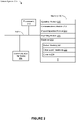
- FIG 2 is a block diagram illustrating an exemplary server system 200 in accordance with some implementations.
- the server system 200 is an example of a server system 104 ( Figure 1 ).
- the server system 104 is distinct and separate from the edge devices 102-1, 102-2, ... 102-n.
- the server system 104 is part of the edge devices 102-1, 102-2, ... 102-n (or part of a respective edge device).
- the server system 200 typically includes one or more processing units (processors or cores) 202, one or more network or other communications interfaces 204, memory 206, and one or more communication buses 208 for interconnecting these components.
- the communication buses 208 optionally include circuitry (sometimes called a chipset) that interconnects and controls communications between system components.
- the server system 200 optionally includes a user interface (not shown).
- the user interface if provided, may include a display device and optionally includes inputs such as a keyboard, mouse, trackpad, and/or input buttons.
- the display device includes a touch-sensitive surface, in which case the display is a touch-sensitive display.
- Memory 206 includes high-speed random access memory, such as DRAM, SRAM, DDR RAM, or other random access solid state memory devices; and may include non-volatile memory, such as one or more magnetic disk storage devices, optical disk storage devices, flash memory devices, or other non-volatile solid state storage devices. Memory 206 may optionally include one or more storage devices remotely located from the processor(s) 202. Memory 206, or alternately the non-volatile memory device(s) within memory 206, includes a non-transitory computer readable storage medium. In some implementations, memory 206 or the computer readable storage medium of memory 206 stores the following programs, modules, and data structures, or a subset or superset thereof:
- the one more defect models 220 include previously identified defects and/or desired results (i.e., non-defect pixels).
- the one or more criteria and thresholds 222 can include thresholds for identifying a defect. For example, a threshold difference (or threshold similarity) between a piece of an image captured and a defect pixel included in a defect model 220. Additionally, in some implementations, an image is not deemed to include a defect until a threshold number of pieces of the image are deemed to include defects.
- the content 224 can include data received from the robotic arm 300 ( Figure 3 ), such as images captured by the robotic arm.
- the content 230 includes text (e.g., ASCII, SGML, HTML), images (e.g., jpeg, tif and gif), graphics (e.g., vector-based or bitmap), audio, video (e.g., mpeg), other multimedia, and/or combinations thereof.
- the server database 218 stores data associated with the server system 200 in one or more types of databases, such as text, graph, dimensional, flat, hierarchical, network, object-oriented, relational, and/or XML databases.
- databases such as text, graph, dimensional, flat, hierarchical, network, object-oriented, relational, and/or XML databases.
- the server system 200 stores in memory a graph of the edge devices.
- the graph identifies each edge device on a particular production line and connections between each edge device.
- the connections may include a position of the edge device, an orientation of the edge device, neighboring edge devices, etc.
- FIG 3 is a block diagram illustrating an exemplary robotic arm 300, in accordance with some implementations.
- the robotic arm 300 is an example of one of the one or more edge devices 102-1, 102-2, ... 102-n ( Figure 1 ).
- the robotic arm 300 typically includes one or more processing units (processors or cores) 302, one or more network or other communications interfaces 304, memory 306, one or more communication buses 308 for interconnecting these components, and actuators 309 (e.g., rotatable joints 406-A - 406-D, Figure 4A ).
- the communication buses 308 optionally include circuitry (sometimes called a chipset) that interconnects and controls communications between system components.
- the robotic arm 300 optionally includes a location detection device 310, such as a GNSS (e.g., GPS, GLONASS, etc.) or other geo-location receiver, for determining the location of the robotic arm 300.
- a location detection device 310 such as a GNSS (e.g., GPS, GLONASS, etc.) or other geo-location receiver, for determining the location of the robotic arm 300.
- the robotic arm 300 also includes one or more capture devices 312, such as a camera, an infrared camera, an X-ray camera, a depth camera, a three-dimensional camera, and the like.
- the robotic arm 300 includes one or more optional sensors (e.g., gyroscope, accelerometer) for detecting motion and/or a change in orientation of the robotic arm 300.
- the detected motion and/or orientation of the robotic arm 300 is used during positioning of the robotic arm 300, or to indicate that the robotic arm 300 requires adjusting or realigning.
- the robotic arm 300 includes, or controls, a rotatable base 311 (e.g., rotatable base 410, Figure 4A ). In some implementations, the robotic arm 300 communicates with the rotatable base 311 via the one or more communication buses 308. Alternatively, in some implementations, the robotic arm 300 communicates with the rotatable base 311 via communication interface(s) 304 and communication interface 313, respectively. In some implementations, the server system 200 controls the rotatable base 311.
- a rotatable base 311 e.g., rotatable base 410, Figure 4A
- the robotic arm 300 communicates with the rotatable base 311 via the one or more communication buses 308. Alternatively, in some implementations, the robotic arm 300 communicates with the rotatable base 311 via communication interface(s) 304 and communication interface 313, respectively.
- the server system 200 controls the rotatable base 311.
- Memory 306 includes high-speed random-access memory, such as DRAM, SRAM, DDR RAM, or other random-access solid-state memory devices; and may include non-volatile memory, such as one or more magnetic disk storage devices, optical disk storage devices, flash memory devices, or other non-volatile solid-state storage devices. Memory 306 may optionally include one or more storage devices remotely located from the processor(s) 306. Memory 306, or alternately the non-volatile memory device(s) within memory 306, includes a non-transitory computer-readable storage medium. In some implementations, memory 306 or the computer-readable storage medium of memory 306 stores the following programs, modules, and data structures, or a subset or superset thereof:
- the positioning module 318 includes a rotatable base module 334 that is used for controlling (i.e., rotating) the rotatable base 311.
- the rotatable base module 334 rotates the rotatable base 311 according to a location of a defect identified in an image captured by the capture device(s) 312.
- the rotatable base module 334 rotates the rotatable base 311 to an initial position prior to capturing the image (e.g., the first image 500, Figure 5B ).
- the one more defect models 328 include previously identified defects and/or desired results (i.e., non-defect pixels).
- the one or more defect models 328 are discussed in further detail below with reference to Figure 5B and Figures 6A-6B .
- the content 330 includes data captured by the capture device(s) 312.
- the content 334 includes text (e.g., ASCII, SGML, HTML), images (e.g., jpeg, tif and gif), graphics (e.g., vector-based or bitmap), audio, video (e.g., mpeg), other multimedia, and/or combinations thereof.
- the content 330 includes local binary patterns (LBP) generated by the robotic arm 300.
- LBP local binary patterns
- the movement algorithms 332 are forward and inverse kinematic equations.
- the forward and inverse kinematic equations are used to identify a position of an end effector (or end effectors) of the robotic arm 300 and determine joint parameters that provide a desired position for each of the robotic arm's end-effectors, respectively.
- the other equations 332 may include working space equations and searching route equations, each of which are described in further detail below.
- modules and applications correspond to a set of executable instructions for performing one or more functions as described above and/or in the methods described in this application (e.g., the computer-implemented methods and other information processing methods described herein).
- modules i.e., sets of instructions
- memory 206 and/or 306 store a subset of the modules and data structures identified above.
- memory 206 and/or 306 optionally store additional modules and data structures not described above.
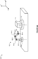
- Figures 4A-4C show exemplary robotic arms used to inspect products, in accordance with some implementations.
- Figure 4A is an exemplary robotic arm 402 used to inspect a product 412, in accordance with some implementations.
- the robotic arm 402 is part of a production line 400, which also includes a rotatable base 410 and a product 412 disposed on top of the rotatable surface 410.
- the robotic arm 402 is an example of the robotic arm 300 ( Figure 3 ). It should be noted that the robotic arm 402 can be used to inspect a wide arrange of products, and the product 412 is merely one example.
- the robotic arm 402 includes a plurality of segments (or sections) 404-A, 404-B, and 404-C.
- a length of each of the plurality of segments 404-A, 404-B, and 404-C is substantially the same.
- a length of at least one segment of the plurality of segments 404-A, 404-B, and 404-C differs from lengths of other segments of the plurality of segments.
- the lengths shown in Figure 4A are simply used for illustrative purposes and are not limiting.
- the second segment 404-B is shown to be shorter than the first segment 404-A, in some implementations, the second segment 404-B is longer than the first segment 404-A (the third segment 404-C may also be longer or shorter than the other segments, depending on the circumstances).
- the robotic arm 402 is shown to include three segments, however, the robotic arm 402 can include various numbers of segments (e.g., two segments, four segments, ... N-segments).
- the robotic arm 402 also includes a plurality of rotatable joints 406-A - 406-D (e.g., actuators 309, Figure 3 ).
- a number of rotatable joints included in the plurality of rotatable joints 406-A - 406-D corresponds to a number of segments in the plurality of segments 404-A, 404-B, and 404-C (e.g., the number of rotatable joints in the plurality is one greater than the number of the plurality of segments).
- the first rotatable joint 406-A rotates about a first axis of rotation (e.g., Y-axis)
- the second rotatable joint 406-B and the third rotatable joint 406-C rotate about a second axis of rotation (e.g., Z-axis)
- the fourth rotatable joint 406-D rotates about one or more of the first axis of rotation and the second axis of rotation.
- the fourth rotatable joint 406-D also rotates about a third axis of rotation (e.g., X-axis).
- the rotatable joints can rotate clockwise and/or counterclockwise, and the arrows used in Figures 4A-4C should not be construed as limiting a rotatable joints' direction of rotation.
- each rotatable joint 406 connects either: (i) two segments of the plurality of segments 404, or (ii) a camera 408 (discussed below) of the robotic arm 402 with one segment of the plurality of segments 404.
- the robotic arm 402 is composed of substantially contiguous segments.
- the robotic arm 402 also includes a camera 408 (e.g., a capture device 312, Figure 3 ) attached to an end of the robotic arm.
- the robotic arm 402 (or a component thereof such as processor(s) 302 or capture module 320, Figure 3 ) controls operation of the camera 408.
- the robotic arm 402 captures an image of the product 412, via the camera 408, after positioning the camera 408 at a desired location. Additionally, in some implementations, the robotic arm 402 controls other features/functions of the camera 408, such as zoom (e.g., the robotic arm 402 adjusts a focal length of the camera 408) and video based features/functions.
- the robotic arm 402 positions the camera 408 substantially adjacent to a surface (or feature) of the product 412. Additionally, in some implementations, the robotic arm 402 positions the camera 408 so that the camera 408 is centered about the surface (or the feature) of the product 412. To accomplish this, the robotic arm 402 actuates (e.g., processor(s) 302 and/or positioning module 318) one or more of the plurality of rotatable joints 406-A - 406-C. In this way, the camera 408 captures an image of the surface of the product 412, and the robotic arm 402 (or server system 200, Figure 2 ) evaluates the image for defects.
- the robotic arm 402 or server system 200, Figure 2
- the robotic arm 402 uses kinematic equations (e.g., forward and/or inverse kinematics) when positioning the camera 408 at a desired location.
- kinematic equations e.g., forward and/or inverse kinematics
- the kinematic equations are also referred to herein as movement algorithms 332 ( Figure 3 ).
- the production line 400 includes a rotatable base 410.
- the robotic arm 402 (or a component thereof such as the processor(s) 302 or rotatable base module 334, Figure 3 ) controls the rotatable base 410.
- the rotatable base is controlled by some other computing device, e.g., the server system 200 ( Figure 2 ). Including the rotatable base 410 in the production line 400: (i) allows the robotic arm 402 to evaluate surfaces and/or features of the product 412 with minimal movement, and (ii) reduces a length of each of the plurality of segments 404-A - 404-C.
- the rotatable base 410 rotates the product 412 to present each lateral surface of the product 412 to the camera 408.
- the robotic arm 402 remains substantially stationary while each lateral surface is placed in front of it (the robotic arm 402 need only reach a top surface of the product 412 as opposed to distant surfaces of the product 412, e.g., as shown in Figures 4B-4C ).
- the robotic arm 402 when positioning the camera 408, the robotic arm 402 considers a field of view of the camera 408. For example, depending on a size of the product being captured, the robotic arm 402 must place the camera 408 at a specific distance away from the product 412 to capture an entire surface of the product 412. This specific distance is dependent on the camera's field of view.
- An exemplary field of view may be a 60 degree field of view, but other fields of view are possible (e.g., depending on lens type, focal length, camera type, etc.).
- the field of view ( ⁇ ) is represented in the working space equations below.
- the robotic arm 402 identifies its working space by capturing an initial image of the product 412 (or by evaluating a video feed taken by the camera). For example, in some circumstances, the product 412 is a smaller product, such as a tea kettle, which requires a first working space. However, in some other circumstances, the product 412 is a larger product, such as a refrigerator, which requires a second working space different from the first working space.
- the end effector of the robotic arm 402 is the camera 408.
- the end effector of the robotic arm 402 is one of the plurality of rotatable joints (or multiple rotatable joints). It should be noted that the rotatable base 410 is factored into the working space equation above. Additionally, working spaces for various products may be stored in memory 306 ( Figure 3 ) of the robotic arm.
- the robotic arm 402 is able to identify differences in sizes between products, and the robotic arm 402 is able to position itself accordingly to capture an initial image of the product 412 that is substantially adjacent to and centered about a surface (or feature) of the product 412. In this way, the production line 400 can use a single robotic arm, as opposed to having multiple robotic arms that are calibrated for certain products, thereby lowering an overall cost for the production line 400.
- Figure 4B is an exemplary robotic arm 420 used to inspect a product 412, in accordance with some implementations.
- the robotic arm 420 is an example of the robotic arm 300 ( Figure 3 ).
- One or more features shown and/or described above with reference to Figure 4A are not described in Figure 4B for the sake of brevity (or certain features have a shortened description).
- the robotic arm 420 includes a plurality of segments (or sections) 424-A, 424-B, and 424-C.
- a length of each of the plurality of segments 424-A, 424-B, and 424-C is substantially the same.
- a length of at least one segment of the plurality of segments 424-A, 424-B, and 424-C differs from the other segments of the plurality of segments.
- the robotic arm 420 is shown to include three segments, it should be understood that the robotic arm 420 can include various numbers of segments (e.g., two segments, four segments, ... N-segments).
- the robotic arm 420 also includes a plurality of rotatable joints 426-A - 426-D.
- a number of joints included in the plurality of rotatable joints 426-A - 426-D corresponds to a number of segments in the plurality of segments 424-A, 424-B, and 424-C (e.g., the number of joints will be one greater than the number of the plurality of segments).
- first rotatable joint 426-A rotates about a first axis of rotation (e.g., Y-axis)
- second rotatable joint 426-B and the third rotatable joint 426-C rotate about a second axis of rotation (e.g., Z-axis)
- fourth rotatable joint 426-D rotates about the first axis of rotation and the second axis of rotation.
- lengths of the plurality segments 424-A - 424-C of the robotic arm 420 are substantially greater than lengths of the plurality segments 404-A - 404-C of the robotic arm 402. This is because the product 412 is placed on top of a stationary base 430, and therefore, the robotic arm 420 is required to reach each surface of the product 412. As a result of not having the rotatable base 410, the fourth rotatable joint 426-D rotates about the first axis of rotation and the second axis of rotation.
- the robotic arm 420 also includes a camera 428 (e.g., capture device 312, Figure 3 ) attached to an end of the robotic arm 420.
- the robotic arm 420 uses the procedures discussed above with reference to Figure 4A to position the camera 428 substantially adjacent to and centered about a surface (or feature) of the product 412.
- the robotic arm 420 identifies its working space by capturing an initial image of the product 412 (or by evaluating a video feed taken by the camera 428).
- Figure 4C is an exemplary robotic arm 440 used to inspect a product 412, in accordance with some implementations.
- the robotic arm 440 is an example of the robotic arm 300 ( Figure 3 ).
- One or more features described above with reference to Figure 4A are not described in Figure 4C for the sake of brevity (or certain features have a shortened description).
- the robotic arm 440 includes a plurality of segments (or sections) 444-A, 444-B, and 444-C.
- a length of each of the plurality of segments 444-A, 444-B, and 444-C is substantially the same.
- a length of at least one of the plurality of segments 444-A, 444-B, and 444-C differs from the other segments of the plurality of segments.
- the robotic arm 440 is shown to include three segments, it should be understood that the robotic arm 440 can include various numbers of segments (e.g., two segments, four segments, ... N-segments).
- the robotic arm 440 also includes a plurality of rotatable joints 446-A - 446-D.
- a number of joints included in the plurality of rotatable joints 446-A - 446-D corresponds to a number of segments in the plurality of segments 444-A, 444-B, and 444-C (e.g., the number of joints will be one greater than the number of the plurality of segments).
- first rotatable joint 446-A rotates about a first axis of rotation (e.g., X-axis)
- second rotatable joint 446-B and the third rotatable joint 446-C rotate about a second axis of rotation (e.g., Z-axis)
- fourth rotatable joint 446-D rotates about one or more of the second axis of rotation and a third axis of rotation (e.g., Y-axis).
- the robotic arm 440 also includes a camera 448 (e.g., capture device 312, Figure 3 ) attached to an end of the robotic arm.
- the robotic arm 440 uses the procedures discussed above with reference to Figure 4A to position the camera 448 substantially adjacent to and centered about a surface (or feature) of the product 412.
- lengths of the plurality segments 444-A - 444-C of the robotic arm 440 are substantially greater than lengths of the plurality segments 404-A - 404-C of the robotic arm 402. This is because the product 412 is placed on top of a stationary base 450, and therefore, the robotic arm 440 is required to reach each surface of the product 412.
- the robotic arm 440 is able to capture the five exposed surface of the product 412 with fewer joint actuations than the robotic arm 420.
- the robotic arm 440 e.g., the first rotatable joint 446-A rotates about the X-axis, and therefore three surfaces of the product 412 can be captured by actuating the first rotatable joint 446-A).
- the robotic arm 440 identifies its working space by capturing an initial image of the product 412 (or by evaluating a video feed taken by the camera 448).
- the rotatable base 410 is not part
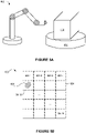
- Figures 5A-5B show a robotic arm 402 capturing a first image 500 of a product 412, and a result of the capturing, in accordance with some implementations.
- the robotic arm 402 (or a component thereof such as the processor(s) 302 or a positioning module 318, Figure 3 ) positions the camera 408 so that the camera 408 is substantially adjacent to and centered about a surface (or feature) of the product 412.
- the robotic arm 402 accomplishes this by first identifying the product 412 to be captured (e.g., microwave oven versus refrigerator), and based on the identified product, the robotic arm 402 determines its working space, which factors in a field of view of the camera 408. Additionally, the robotic arm 402 executes one or more kinematic equations to position itself.
- the robotic arm 402 positions the camera 408 at a sufficient distance away from the surface of the product 412 so that the camera 408 captures an acceptable image (e.g., an image that includes the entire surface, or an entire feature).
- an acceptable image e.g., an image that includes the entire surface, or an entire feature.
- Figure 5B shows a first image 500 captured by the camera 408.
- the first image 500 includes the surface 501 of the product 412 captured by the camera 408, and a defect 502 on the surface 501.
- the robotic arm 402 (or a component thereof such as the processor(s) 302 or an image inspection module 324, Figure 3 ) identifies the defect 502 by processing (e.g., analyzing, evaluating, etc.) the first image 500.
- processing the first image 500 involves comparing portions (e.g., pieces) of the first image 500 with one or more defect models (e.g., defect model(s) 328, Figure 3 ).
- the robotic arm 402 divides the first image 500 into pieces 504-1 - 504-N (e.g., forms a grid, where each piece of the grid has an equal size) and compares at least a subset of the pieces 504-1 - 504-N with one or more defect models (e.g., defect model 600, Figure 6A ).
- the defect model 600 includes defect pixels 602-A - 602-N.
- a "defect pixel" is a 1 x 1 pixel, while in some other implementations, a defect pixel includes multiple pixels (e.g., a 25 x 25 pixel, a 100 x 100 pixel, or some greater or lesser number of pixels).
- the defect pixels corresponds to the pieces of the first image 500 (e.g., a top left corner of defect model 600 includes defect pixels that correspond to a top left corner of the first image 500).
- the robotic arm 402 compares a first piece 504-1 of the first image 500 with one or more corresponding defect pixels from a defect model for the surface 501 of the product 412 (e.g., defect pixel 602-A, Figure 6A ).
- the robotic arm 402 flips the one or more corresponding defect pixels left to right and/or top to bottom, during the comparison.
- the robotic arm 402 rotates the one or more corresponding defect pixels 90 degrees, 180 degrees, and/or 270 degrees during the comparison.
- the robotic arm 402 evaluates possible variations of the one or more corresponding defect pixels. It should be noted that “flipping" a defect pixel is not the same as “rotating" a defect pixel (e.g., flipping a defect pixel causes features in the defect pixel to be mirrored in the resulting defect pixel).
- the robotic arm 402 compares pieces of the first image 500 with the defect pixels sequentially. For example, piece 504-1 is compared with one or more first corresponding defect pixels, piece 504-2 is compared with one or more second corresponding defect pixels, and so on. Alternatively, the robotic arm 402 compares pieces of the first image 500 with the defect pixels randomly, or pseudo-randomly. In some implementations, the robotic arm 402 performs an initial analysis of the first image 500 to identify any abnormalities in the first image 500.
- the robotic arm 402 compares one or more pieces in the bottom right corner of the first image 500 with one or more corresponding defect pixels. In this way, the robotic arm 402 skips processing other portions of the first image 500 that do not include abnormalities, thus saving time and computing resources.
- a defect pixel is a previously identified defect.
- the previously identified defect may be identified during a testing/calibration phase and/or during previous inspections (e.g., if the product 412 is a microwave oven, defects on surfaces of previously inspected microwave ovens are logged and stored).
- a defect pixel is a desired result for each piece of the surface 501 of the product 412 (i.e., a non-defect pixel). For example, during a testing/calibration phase, an image of a control surface of a control product is captured, and each piece of the control surface is logged and stored (the control surface corresponding to the surface 501).
- the defect models 328 include a desired result with acceptable tolerances (e.g., a threshold difference from the control surface that is required for an abnormality to be deemed a defect).
- the first image 500 includes a defect 502 in piece 504-5. Accordingly, in response to identifying the defect 502, the robotic arm repositions instead to capture a second image 530 of the surface 501 of the product 512, as shown in Figures 5C-5D . It should be noted that a defect may span several pieces, depending on a size of the defect. For ease of discussion and illustration, the defect 502 is contained within a single piece 504-1.
- the server system 200 ( Figure 2 ), processes the first image 500 instead of the robotic arm 402 (e.g., the robotic arm 402 sends the first image 500 to the server system 200 for evaluation). Moreover, in some implementations, the robotic arm 402 sends the first image 500 to the server system 200 for evaluation after identifying an abnormality in the first image 500.
- Figures 5C-5D show the robotic arm capturing a second image 530 of the product and a result of the capturing, in accordance with some implementations.
- the robotic arm 402 moves (e.g., repositions) itself from a first position 520-A (dotted lines) to a second position 520-B.
- the robotic arm 402 in Figure 5A is positioned at the first position 520-A, and therefore, the robotic arm 402 captures the first image 500 when positioned at the first position 520-A.
- movement between the first position 520-A and the second position 520-B is determined in accordance with the first position 520-A of the camera 408 (or one of the rotatable joints) and a relative location of the defect 502 in the first image 500.
- the second position 520-B is within the working space determined by the robotic arm 402, and the movement between the first position 520-A and the second position 520-B is determined in accordance with the working space.
- the goal of the robotic arm 402 repositioning itself is to focus the camera 408 of the defect 502 (as opposed to capturing the surface 501 in its entirety).
- the robotic arm 402 in response to identifying the defect 502 in the first image 500, rotates the rotatable base 410.
- the rotatable base 410 in Figure 5A is positioned at a first position (showing the product 412-A in a first position (dotted lines)), and therefore, the robotic arm 402 captures the first image 500 when the product 412-A is in the first position.
- the robotic arm 402 rotates the rotatable base 410 to a second position in accordance with a relative location of the defect 502 in the first image 500 (showing the product 412-B in a second position).
- the robotic arm 402 when it repositions itself, it moves the camera 408 in multiple directions. For example, the robotic arm 402 moves the camera 408 along the Y-axis, X-axis, and Z-axis.
- the robotic arm 402 may move the camera 408 in multiple directions when the defect 502 is offset from the center of the first image 500 (e.g., the defect 502 in the first image 500 is offset towards an upper left corner of the surface 501).
- the robotic arm 502 when the defect 502 is not offset vertically from the center of the first image 500, the robotic arm 502 may move the camera 408 in a single direction (e.g., along the X-axis towards the surface 501 of the product 412-B).
- the minimal movement of the camera 408 is achieved because the rotatable base 410 repositions the defect 502 in front of the camera.
- the robotic arm 402 may need to take further repositioning actions.
- the robotic arm 402 uses kinematic equations (e.g., movement algorithms 332, Figure 3 ) when moving from the first position 520-A to the second position 520-B.
- the kinematic equations may include forward kinematic equations and/or inverse kinematic equations.
- Forward kinematics refers to the use of the kinematic equations of a robot to compute the position of the end-effector (e.g., a camera) from specified values for the joint parameters.
- exemplary forward kinematic equations are represented by the following equations: ⁇ d a ⁇ Joint 1 ⁇ 1 0 a1 90° Joint 2 ⁇ 2 0 a2 0 Joint 3 ⁇ 3 0 a3 0 Joint 4 ⁇ 4 0 a4 90°
- ⁇ , d, a, and ⁇ are the Denavit-Hartenberg parameters, as known by those skilled in the art.
- a 1 cos ⁇ 1 0 sin ⁇ 1 a 2 cos ⁇ 1 sin ⁇ 1 0 ⁇ cos ⁇ 1 a 2 sin ⁇ 1 0 1 0 0 0 0 0 1
- a 2 cos ⁇ 2 ⁇ sin ⁇ 2 0 a 2 cos ⁇ 2 sin ⁇ 2 cos ⁇ 2 0 a 2 sin ⁇ 2 0 0 1 0 0 0 0 1
- a 3 cos ⁇ 3 ⁇ sin ⁇ 3 0 a 3 cos ⁇ 3 sin ⁇ 3 cos ⁇ 3 0 a 3 sin ⁇ 3 0 0 1 0 0 0 0 1
- a 4 cos ⁇ 4 0 sin ⁇ 4 a 4 cos ⁇ 4 sin ⁇ 4 0 ⁇ cos ⁇ 4 a 4 sin ⁇ 4 0 1 0 0 0 0 0 1
- a 1234 A
- the robotic arm 402 determines a position of an end effector (e.g., a position of the camera 408, and/or one of the rotatable joints) in a working space defined by the working space equations above.
- an end effector e.g., a position of the camera 408, and/or one of the rotatable joints
- inverse kinematics makes use of the kinematics equations to determine the joint parameters that provide a desired position for each of a robot's end-effectors.
- Inverse kinematics transforms an end-effector's motion plan from a first position to a second position into joint actuator trajectories for the robot.
- the robotic arm 402 uses the inverse kinematic equations presented above to define its searching route (i.e., defining a path of the camera 408 (or one or more of the rotatable joints) from the first position 520-A to the second position 520-B.
- equations above a merely one example of equations that can be used to control movement of the robotic arm 402.
- equations can be used to control movement of the robotic arm 402.
- different equations can be used to control robotic arms 420 and 440. These equations are provided below (after the discussion of method 700).
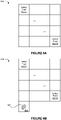
- Figures 6A-6B show a defect model (defect table) 600 and a defect 502 being added to the defect table 600, in accordance with some implementations.
- the defect model 600 e.g., defect model(s) 328, Figure 3
- the defect model 600 includes defect pixels 602-A - 602-N.
- a position of a defect pixel 602 in the defect model 600 corresponds to a piece (or multiple pieces) of an image being inspected (e.g., a top left corner of the defect model 600 includes pixels that correspond to a top left corner of the first image 500, Figure 5B ).
- a first defect model corresponds to a first piece or a first portion of the image being inspected
- a second defect model corresponds to a second piece or a second portion of the image being inspected, and so on.
- the defect pixels 602-A - 602-N in the defect model 600 are previously identified defects.
- a previously identified defect may be identified during a testing/calibration phase and/or during previous inspections (e.g., if the product 412 is a microwave oven, defects on surfaces of previously inspected microwave ovens are logged and stored in the defect model 600).
- a defect pixel 602 is a desired result for a piece of the product being inspected (i.e., a non-defect pixel).
- a testing/calibration phase an image of a control surface of a control product is captured, and each piece of the control surface is logged and stored in the defect model 600.
- this process may be repeated for several control products to form the defect model 600.
- the defect 502 ( Figure 5B ) is added to the defect model 600 after the robotic arm captures the second image 530.
- the defect model 600 includes new defect pixel 604, which includes the defect 502.
- the robotic arm 402 implements machine learning to continually update the defect model 600.
- the defect 502 may be referenced to identify defects on a subsequent product inspected by the robotic arm 402.
- Figure 7 is a flow diagram illustrating a method 700 of improved quality inspection on a product, in accordance with some implementations.
- the steps of the method 700 are performed by a robotic arm (e.g., edge device 102, Figure 1 ; robotic arm 300, Figure 3 ).
- Figure 7 corresponds to instructions stored in a computer memory or computer readable storage medium (e.g., memory 306 of the robotic arm 300).
- the operations of the method 700 are performed, at least in part, by a communications module (e.g., communications module 316, Figure 3 ), a positioning module (e.g., positioning module 318, Figure 3 ), a capture module (e.g., capture module 320, Figure 3 ), and an image inspection module (e.g., image inspection module 324, Figure 3 ).
- a communications module e.g., communications module 316, Figure 3
- a positioning module e.g., positioning module 318, Figure 3
- a capture module e.g., capture module 320, Figure 3
- an image inspection module e.g., image inspection module 324, Figure 3 .
- the robotic arm includes a plurality of segments (e.g., segments 404-A, 404-B, and 404-C, Figure 4A ), a camera at an end of the robotic arm (e.g., camera 408 at end of robotic arm 402, Figure 4A ), and a plurality of rotatable joints (e.g., rotatable joints 406-A - 406-D, Figure 4A ), each rotatable joint connecting two segments of the plurality of segments or the camera with one segment of the plurality of segments (702).
- the plurality of rotatable joints provides the robotic arm with four degrees of freedom.
- the plurality of rotatable joints provides the robotic arm with five degrees of freedom.
- a first set of rotatable joints in the plurality of rotatable joints rotate about a first axis (e.g., Z-axis) and a second set of rotatable joints in the plurality of rotatable joints rotate about a second axis (e.g., Y-axis), or vice versa.
- the first set of rotatable joints is body rotatable joints (e.g., rotatable joints 406-B and 406-C, Figure 4A ) and the second set of rotatable joints is end rotatable joints (e.g., rotatable joints 406-A and 406-D, Figure 4A ).
- At least one of the rotatable joints rotates about two axes (e.g., rotatable joint 406-D, in some implementations, rotates about the Z-axis and the Y-axis, or some other combination of axes).
- the method 700 includes receiving (704) a command to capture a first image of a surface (or a feature) of a product (e.g., product 412, Figure 4A ).
- the robotic arm receives the command from the server system, or some other computer (e.g., a control computer of the production line 400, Figure 4A ).
- the robotic arm recognizes the product placed in front of it. For example, the robotic arm may determine a size of the product from a video feed of the camera, and the size of the product may correspond to a product type (e.g., a product having a first size is a tea kettle and a product having a second size is a microwave oven).
- the robotic arm captures the first image of the surface of the product (discussed below).
- the robotic arm captures an initial image (different from the first image) of the product. Using the initial image, the robotic arm determines a working space for an end effector of the robotic arm.
- the working space may extend from each surface (or feature) of the product to a specific distance away from each surface (or feature) of the product.
- the end effector of the robotic arm is the camera.
- the end effector of the robotic arm is one or more of the plurality of rotatable joints.
- the working space of the end effector is determined based on a shape/size of the product (e.g., height, width, length, and volume of the product).
- the working space of the end effector is determined based on the camera's field of view. Determining the working space of the robotic arm is discussed in further detail above with reference to Figure 4A .
- the method 700 in response to receiving the command (or in response to recognizing the product), the method 700 further includes positioning (706), by actuating the plurality of rotatable joints, the camera at a first position that is substantially adjacent to the surface of the product.
- the camera is centered about the surface of the product when at the first position.
- the camera is adjacent to a predetermined portion of the surface when at the first position (e.g., a defect prone portion of the surface).
- the first position is within the working space determined by the robotic arm, and the camera is the end effector of the robotic arm.
- the robotic arm positions itself in a default position after examining a previous product.
- the default position is a retracted position, which assures an incoming product does not damage the camera (e.g., avoid a collision between camera and the incoming product). This is especially important when a previously examined product is substantially smaller than the incoming product.
- positioning the camera at the first position involves moving the robotic arm from the default position to the first position.
- the robotic arm may use the movement algorithms 332 to move the camera from the default position to the first position.
- the camera is already at the first position.
- a previously examined product such as a microwave oven
- a subsequent product which is the same model microwave oven, may then be examined, thereby not requiring movement of the camera.
- the camera is separated from the surface by a first distance when positioned at the first position. The first distance corresponding to the working space determined by the robotic arm. Moreover, in some implementations, the camera is set at a first focal length when positioned at the first position (e.g., set to a first zoom). In some implementations, the field of view of the camera is based, at least in part, on a focal length of the camera. Accordingly, in some implementations, the robotic arm adjusts a focal length of the camera when determining the working space (e.g., zooms in or out, depending on the circumstances).
- the method 700 further includes capturing (708), via the camera, the first image of the surface of the product with the camera positioned at the first position (e.g., the first position 520-A, Figure 5C ).
- the first image 500 includes a surface 501 of the product 412.
- the method 700 further includes, after capturing the first image, processing (710) the first image to identify a defect in the first image and a relative location of the defect in the first image.
- processing the first image includes comparing pieces of the first image with one or more defect models (e.g., one or more defect models 328, Figure 3 ).
- the robotic arm divides the first image into pieces (e.g., pieces 504-1 - 504-N, Figure 5B ) and compares at least a subset of the pieces with one or more defect models.
- the defect model 600 includes defect pixels 602-A - 602-N.
- a defect pixel is a 1 x 1 pixel.
- a defect pixel includes multiple pixels (e.g., a 25 x 25 pixel, a 100 x 100 pixel, or some greater or lesser number of pixels). Processing an image is discussed in further detail above with reference to Figure 5B .
- processing the first image also includes performing an initial analysis of the first image to identify any abnormalities in the first image.
- the initial analysis may include comparing regions of the first image with a template (i.e., control) of the surface of the product (e.g., less demanding analysis than the comparing operation discussed above).
- the template of the surface includes a desired result of the surface (e.g., a previously examined surface of the product that passed quality control). If an abnormality is found, e.g., a bottom right corner of the first image differs from the template, then the robotic arm compares one or more pieces in the bottom right corner of the first image with one or more corresponding defect pixels (as discussed above).
- an abnormality as used herein is not necessarily a defect, but is instead a deviation from a control/template. However, an abnormality can be transformed into a defect with further investigation.
- the method 700 further includes determining (712) whether the first image includes a defect based on the processing (i.e., based on comparing the pieces of the first image with one or more defect models).
- the robotic arm determines that the first image includes a defect when a piece (or a threshold number of pieces) of the first image either: (1) matches (or partially matches) a defect pixel in the defect model, or (2) does not match (or partially match) any non-defect pixels in the defect model.
- a partially match is deemed sufficient when a threshold percentage of the defect matches the defect pixel.
- the defect model in some implementations, includes "non-defect pixels," which are desired results for pieces of the product (e.g., pieces of the product that previously passed quality control, and were logged in a defect model 328, Figure 3 ). Determining that an image incudes a defect is discussed in further detail above with reference to Figure 5B .
- the robotic arm creates a local binary pattern (LBP) to determine whether the first image includes a defect.
- LBP local binary pattern
- a value is assigned to a piece based on the processing (710). For example, a first value is assigned to the piece when the piece directly matches a defect pixel (e.g., a 90% match) and a second value, less than the first value, is assigned to the piece when the piece partially matches a defect pixel (e.g., 60% match) (values may also assigned using non-defect pixels).
- the value of the piece is compared to values of neighboring pieces (e.g., any given piece has eight neighboring pieces).
- a total metric is assigned to the piece.
- the metric is an eight digit binary number with each digit corresponding to one of the eight comparisons.
- a region (e.g., a first location) of the histogram having a first binary number (or an average first binary number) may indicate that that region includes a defect and a different region (e.g., a second location) of the histogram having a second binary number (or an average second binary number) may indicate that that region does not include a defect.
- the histogram may be an N-number dimensional feature vector, and in some implementations, the histogram is normalized. In such implementations, a feature vector is established for the first image.
- a support vector machine is also used to determine that the first image includes a defect.
- the SVM is a supervised learning model in machine learning with associated learning algorithms that analyze data used for classification and regression analysis. For example, given a set of training examples, each marked as belonging to one or the other of two categories, an SVM training algorithm builds a binary classifier that assigns new examples to one category or the other.
- An SVM model is a representation of the examples as points in space, mapped so that the examples of the separate categories are divided by a clear gap that is as wide as possible. New examples are then mapped into that same space and predicted to belong to a category based on which side of the gap they fall.
- the SVM determines that the first image includes a defect using the LBP discussed above.
- the method 700 further includes recording and reporting (714) the product as acceptable.
- the method 700 further includes determining (716) a second position of the camera in accordance with the first position of the camera and the relative location of the defect in the first image.
- the robotic arm may be determining that the first image likely has a defect. As such, as is discussed below, the robotic arm captures a second image of the surface to verify that the identified defect is actually a defect.
- the method 700 further includes repositioning (718), by actuating the plurality of rotatable joints, the camera from the first position to the second position.
- the second position has a different spatial relationship to the surface of the product than the first position.
- the camera is separated from the surface by a second distance when repositioned at the second position, and the second distance is less than the first distance.
- the camera is set at a second focal length when repositioned at the second position, and the second focal length is greater than the first focal length (e.g., set to a second zoom).
- the goal of the robotic arm repositioning itself is to focus the camera of the defect (as opposed to capturing the surface in its entirety). For example, as shown in Figure 5D , the defect is magnified in a center portion of the second image 530. In this way, the robotic arm can verify that the identified defect is actually a defect
- the method 700 further includes capturing (720), via the camera, the second image of the surface of the product with the camera positioned at the second position.
- the robotic arm verifies that the identified defect is actually a defect.
- the robotic arm again compares the defect with defect pixels (and/or non-defect pixels) in the defect model. This comparison operation, however, is more granular relative to the first image's comparison operation.
- the robotic may determine that the defect corresponds to an already identified defect (e.g., a defect caused by a tool). Alternatively, the robotic may determine that the defect does not correspond to any already identified defect, but it is nevertheless a defect.
- the robotic arm may generate a report and provide the report to the appropriate party (e.g., a processing engineer responsible for a specific part of the manufacturing process).
- the method 700 includes recording and reporting the product as unacceptable.
- the method 700 further includes updating the defect model to include the defect.
- new defect pixel 604 which includes the defect 502 is added to the defect model 610.
- the defect is added to the defect model after step 712-Yes.
- the defect is added to the defect model after verifying the defect.
- the robotic arm cannot verify the defect.
- the method 700 includes recording and reporting the product as acceptable.
- the robotic arm may update the defect model to include the non-verified defect as being an acceptable abnormality (i.e., a non-defect pixel).
- the product is positioned on a rotatable base (e.g., rotatable base 311, Figure 3 ; rotatable base 410, Figure 4A ).
- the method 700 includes rotating the rotatable base in accordance with the relative location of the defect in the first image after capturing the first image. The second image is then captured after rotating the rotatable base.
- the robotic arm or a component thereof such as processors 302 or rotatable base module 334, Figure 3 ) controls the rotatable base and rotates the rotatable base so that the defect is positioned in front of the camera.
- This configuration minimizes a degree of movement required by the robotic arm because the defect essentially comes to the camera instead of the camera going to the defect. As such, time and resources are conserved when the rotatable base is included. Moreover, a length of each segment in the plurality of segments can be substantially reduced because the robotic arm does not have to reach distant lateral surfaces of the product. At most, the robotic arm is required to reach a top surface of the product, assuming that the top surface needs inspecting.
- the method 700 further includes determining a size of the product, and based on the determined size, the robotic arm determines it working space. For example, the robotic arm, when positioned at the default position, detects the product in front of it, and determines the size of the product using an image captured by the camera and the camera's position. In some implementations, in order to determine the size of the product, the robotic arm captures an initial image of the product and determines the size of the product from the initial image and the position of the camera capturing the initial image. Alternatively, in some implementations, the robotic arm evaluates the product based on a video feed from the camera.
- the method 700 further includes repositioning, by actuating the plurality of rotatable joints, the camera at one or more additional positions, where each additional position is substantially adjacent to a respective additional surface (or an additional feature) of the product.
- the robotic arms 420 and 440 reach distant lateral surfaces of the product 412.
- the robotic arm can leverage the rotatable base to rotate the product so that each respective additional surface of the product is positioned in front of the camera. Again, this arrangement results in the additional surfaces coming to the camera instead of the camera going to the defect. In this way, time and resources are conserved.
- the method 700 further includes capturing, via the camera, an additional image of each respective additional surface of the product with the camera positioned at the one or more additional positions.
- Each additional image is processed in the same manner as discussed above.
- the robotic arm 420 uses kinematic equations (e.g., movement algorithms 332, Figure 3 ) when moving from one position to another.
- the kinematic equations may include forward kinematic equations and/or inverse kinematic equations.
- exemplary forward kinematic equations are represented by the following equations: ⁇ d a ⁇ Joint 1 ⁇ 1 0 ⁇ 1 90° Joint 2 ⁇ 2 0 ⁇ 2 0 Joint 3 ⁇ 3 0 ⁇ 3 0 Joint 4 ⁇ 4 0 0 0 0 Joint 5 ⁇ 5 0 0 90°
- ⁇ , d, a, and ⁇ are the Denavit-Hartenberg parameters, as known by those skilled in the art.
- a 1 cos ⁇ 1 0 sin ⁇ 1 a 2 cos ⁇ 1 sin ⁇ 1 0 ⁇ cos ⁇ 1 a 2 sin ⁇ 1 0 1 0 0 0 0 0 1
- a 2 cos ⁇ 2 ⁇ sin ⁇ 2 0 a 2 cos ⁇ 2 sin ⁇ 2 cos ⁇ 2 0 a 2 sin ⁇ 2 0 0 1 0 0 0 0 1
- a 3 cos ⁇ 3 ⁇ sin ⁇ 3 0 a 3 cos ⁇ 3 sin ⁇ 3 cos ⁇ 3 0 a 3 sin ⁇ 3 0 0 1 0 0 0 0 1
- a 4 cos ⁇ 4 0 sin ⁇ 4 a 4 cos ⁇ 4 sin ⁇ 4 0 ⁇ cos ⁇ 4 a 4 sin ⁇ 4 0 1 0 0 0 0 0 1
- a 5 cos
- C 1 a x + S 1 a y ⁇ ⁇ 2 atan S 3
- C 3 C 1 p x + S 1 p y ⁇ a 1 2 + p z 2 ⁇ a 2 2 ⁇ a 3 2 2 a 2 a 3
- the robotic arm 420 uses the inverse kinematic equations presented above to define its searching route (i.e., defining a path of the camera 428 (or one or more of the rotatable joints) from a first position to a second position).
- the robotic arm 440 uses kinematic equations (e.g., movement algorithms 332, Figure 3 ) when moving from one position to another.
- the kinematic equations may include forward kinematic equations and/or inverse kinematic equations.
- exemplary forward kinematic equations are represented by the following equations: ⁇ d a ⁇ Joint 1 ⁇ 1 0 ⁇ 1 90° Joint 2 ⁇ 2 0 ⁇ 2 0 Joint 3 ⁇ 3 0 ⁇ 3 0 Joint 4 ⁇ 4 0 0 90° where ⁇ , d, a, and ⁇ are the Denavit-Hartenberg parameters, as known by those skilled in the art.
- a 1 cos ⁇ 1 0 sin ⁇ 1 a 2 cos ⁇ 1 sin ⁇ 1 0 ⁇ cos ⁇ 1 a 2 sin ⁇ 1 0 1 0 0 0 0 0 1
- a 2 cos ⁇ 2 ⁇ sin ⁇ 2 0 a 2 cos ⁇ 2 sin ⁇ 2 cos ⁇ 2 0 a 2 sin ⁇ 2 0 0 1 0 0 0 0 1
- a 3 cos ⁇ 3 ⁇ sin ⁇ 3 0 a 3 cos ⁇ 3 sin ⁇ 3 cos ⁇ 3 0 a 3 sin ⁇ 3 0 0 1 0 0 0 0 1
- a 4 cos ⁇ 4 0 sin ⁇ 4 a 4 cos ⁇ 4 sin ⁇ 4 0 ⁇ cos ⁇ 4 a 4 sin ⁇ 4 0 1 0 0 0 0 0 1
- a 1234 C
- C 1 a x + S 1 a y ⁇ ⁇ 2 atan S 3
- C 3 C 1 p x + S 1 p y ⁇ a 1 2 + p z 2 ⁇ a 2 2 ⁇ a 3 2 2 a 2 a 3
- the robotic arm 440 uses the inverse kinematic equations presented above to define its searching route (i.e., defining a path of the camera 448 (or one or more of the rotatable joints) from a first position to a second position).
- stages which are not order dependent may be reordered and other stages may be combined or broken out. While some reordering or other groupings are specifically mentioned, others will be obvious to those of ordinary skill in the art, so the ordering and groupings presented herein are not an exhaustive list of alternatives. Moreover, it should be recognized that the stages could be implemented in hardware, firmware, software or any combination thereof.
Landscapes
- Engineering & Computer Science (AREA)
- Physics & Mathematics (AREA)
- General Physics & Mathematics (AREA)
- Quality & Reliability (AREA)
- Computer Vision & Pattern Recognition (AREA)
- Theoretical Computer Science (AREA)
- Biochemistry (AREA)
- Robotics (AREA)
- Pathology (AREA)
- Immunology (AREA)
- General Health & Medical Sciences (AREA)
- Health & Medical Sciences (AREA)
- Life Sciences & Earth Sciences (AREA)
- Chemical & Material Sciences (AREA)
- Analytical Chemistry (AREA)
- Mechanical Engineering (AREA)
- Automation & Control Theory (AREA)
- Manufacturing & Machinery (AREA)
- General Engineering & Computer Science (AREA)
- Manipulator (AREA)
- Investigating Materials By The Use Of Optical Means Adapted For Particular Applications (AREA)
- Image Analysis (AREA)
- Length Measuring Devices By Optical Means (AREA)
Claims (13)
- Bras robotique (300, 402, 420, 440) comprenant :une pluralité de segments (404-A-C, 424-A~C, 444-A~C) ;une caméra (408, 428, 448) à une extrémité du bras robotique (300, 402, 420, 440) ;une pluralité d'articulations rotatives (406-A~D, 426-A~D, 446-A~D), chaque articulation rotative (406-A~D, 426-A~D, 446-A~D) reliant deux segments de la pluralité de segments (404-A-C, 424-A~C, 444-A~C) ou la caméra (408, 428, 448) avec un segment de la pluralité de segments (404-A~C, 424-A~C, 444-A~C) ;un ou plusieurs processeurs (202, 302) ; etune mémoire (206, 306) stockant un ou plusieurs modèles de défaut (220, 328), et un ou plusieurs programmes destinés à être exécutés par le ou les processeurs (202, 302), le ou les programmes comportant des instructions pour :recevoir une commande pour capturer une première image (500) d'une surface (501) d'un produit (412) ;positionner, en actionnant la pluralité d'articulations rotatives (406-A~D, 426-A~D, 446-A~D), la caméra (408, 428, 448) à une première position (520-A) qui est sensiblement adjacente à la surface (501) du produit (412) ;capturer, par l'intermédiaire de la caméra (408, 428, 448), la première image (500) de la surface (501) du produit (412) avec la caméra (408, 428, 448) positionnée à la première position (520-A) ; etaprès avoir capturé la première image (500) :traiter la première image (500) pour identifier un défaut (502) sur la surface du produit dans la première image (500) et un emplacement relatif du défaut (502) dans la première image (500), par :division de la première image (500) en une pluralité de parties d'image ; etcomparaison d'au moins un sous-ensemble des parties d'image avec le ou les modèles de défaut (328), pour identifier ledit défaut (502) dans au moins une desdites parties d'image ;déterminer une deuxième position (520-B) de la caméra (408, 428, 448) en fonction de la première position (520-A) de la caméra (408, 428, 448) et de l'emplacement relatif du défaut (502) dans la première image (500), où la deuxième position (520-B) a une relation spatiale avec la surface (501) du produit (412) différente de la première position (520-A) pour focaliser ladite caméra sur ledit défaut identifié dans ladite au moins une desdites parties d'image ;repositionner, en actionnant la pluralité d'articulations rotatives (406-A~D, 426-A~D, 446-A~D), la caméra (408, 428, 448) de la première position (520-A) à la deuxième position (520-B) ;capturer, par l'intermédiaire de la caméra (408, 428, 448), une deuxième image (530) du défaut identifié sur la surface (501) du produit (412) avec la caméra (408, 428, 448) positionnée à la deuxième position (520-B) ; etajouter, après avoir capturé la deuxième image, les pixels du défaut dans la deuxième image au ou aux modèles de défaut.
- Bras robotique selon la revendication 1, où :la caméra (408, 428, 448) est séparée de la surface (501) par une première distance lorsqu'elle est positionnée à la première position (520-A) ;la caméra (408, 428, 448) est séparée de la surface (501) par une deuxième distance lorsqu'elle est repositionnée à la deuxième position (520-B) ; etla deuxième distance est inférieure à la première distance.
- Bras robotique selon la revendication 1, où :la caméra (408, 428, 448) est réglée à une première distance focale lorsqu'elle est positionnée à la première position (520-A) ;la caméra (408, 428, 448) est réglée à une deuxième distance focale lorsqu'elle est repositionnée à la deuxième position (520-B) ; etla deuxième distance focale est supérieure à la première distance focale.
- Bras robotique selon la revendication 1, où le ou les programmes comportent en outre des instructions pour :déterminer une taille du produit (412) à partir de la première image (500) de la surface (501) du produit (412) et de la première position (520-A) de la caméra (408, 428, 448) ; etsur la base de la taille déterminée, attribuer un espace de travail pour le bras robotique (300, 402, 420, 440).
- Bras robotique selon la revendication 4, où le positionnement de la caméra (408, 428, 448) à la première position (520-A) et le repositionnement de la caméra (408, 428, 448) de la première position (520-A) à la deuxième position (520-B) sont réalisés à l'intérieur de l'espace de travail déterminé pour le bras robotique (300, 402, 420, 440).
- Bras robotique selon la revendication 1, où la pluralité d'articulations rotatives confère au bras robotique quatre ou cinq degrés de liberté ;un premier ensemble d'articulations rotatives dans la pluralité d'articulations rotatives (406-A~D, 426-A~D, 446-A~D) tourne autour d'un premier axe ; etun deuxième ensemble d'articulations rotatives dans la pluralité d'articulations rotatives (406-A~D, 426-A~D, 446-A~D) tourne autour d'un deuxième axe ;le premier ensemble d'articulations rotatives est constitué d'articulations rotatives de corps ; et le deuxième ensemble d'articulations rotatives est constitué d'articulations rotatives d'extrémité.
- Bras robotique selon la revendication 1, où le ou les programmes comportent en outre des instructions pour :repositionner, en actionnant la pluralité d'articulations rotatives (406-A~D, 426-A~D, 446-A~D), la caméra (408, 428, 448) à une ou plusieurs positions supplémentaires, chaque position supplémentaire est sensiblement adjacente à une surface supplémentaire respective du produit (412) ; etcapturer, par l'intermédiaire de la caméra (408, 428, 448), une image supplémentaire de chaque surface supplémentaire respective du produit (412) avec la caméra (408, 428, 448) positionnée au niveau de la ou des positions supplémentaires.
- Procédé d'inspection de qualité améliorée, comprenant :le stockage, dans une mémoire (206, 306), de données définissant un ou plusieurs modèles de défaut (220, 328) ;au niveau d'un bras robotique (300, 402, 420, 440) comprenant une pluralité de segments (404-A~C, 424-A~C, 444-A~C), une caméra (408, 428, 448) à une extrémité du bras robotique (300, 402, 420, 440), et une pluralité d'articulations rotatives (406-A~D, 426-A~D, 446-A~D), chaque articulation rotative (406-A~D, 426-A~D, 446-A~D) reliant deux segments de la pluralité de segments (404-A-C, 424-A~C, 444-A~C) ou la caméra (408, 428, 448) avec un segment de la pluralité de segments (404-A-C, 424-A~C, 444-A~C) :la réception (704) d'une commande pour capturer une première image (500) d'une surface (501) d'un produit (412) ;le positionnement (706), en actionnant la pluralité d'articulations rotatives (406-A~D, 426-A~D, 446-A~D), de la caméra (408, 428, 448) à une première position (520-A) qui est sensiblement adjacente à la surface (501) du produit (412) ;la capture (708), par l'intermédiaire de la caméra (408, 428, 448), de la première image (500) de la surface (501) du produit (412) avec la caméra (408, 428, 448) positionnée à la première position (520-A) ; etaprès avoir capturé la première image (500) :le traitement (710) de la première image (500) pour identifier un défaut (502) sur la surface du produit dans la première image (500) et un emplacement relatif du défaut (502) dans la première image (500), par :division de la première image (500) en une pluralité de parties d'image ; etcomparaison d'au moins un sous-ensemble des parties d'image avec le ou les modèles de défaut (328), pour identifier ledit défaut (502) dans au moins une desdites parties d'image ;la détermination (716) d'une deuxième position (520-B) de la caméra (408, 428, 448) en fonction de la première position (520-A) de la caméra (408, 428, 448) et de l'emplacement relatif du défaut (502) dans la première image (500), où la deuxième position (520-B) a une relation spatiale avec la surface (501) du produit (412) différente de la première position (520-A) pour focaliser ladite caméra sur ledit défaut identifié dans ladite au moins une desdites parties d'image ;le repositionnement (718), en actionnant la pluralité d'articulations rotatives (406-A~D, 426-A~D, 446-A~D), de la caméra (408, 428, 448) de la première position (520-A) à la deuxième position (520-B) ;la capture (720), par l'intermédiaire de la caméra (408, 428, 448), de la deuxième image (530) du défaut identifié sur la surface (501) du produit (412) avec la caméra (408, 428, 448) positionnée à la deuxième position (520-B) ; etl'ajout, après avoir capturé la deuxième image, des pixels du défaut dans la deuxième image au ou aux modèles de défaut.
- Procédé selon la revendication 8, où :la caméra (408, 428, 448) est séparée de la surface (501) par une première distance lorsqu'elle est positionnée à la première position (520-A) ;la caméra (408, 428, 448) est séparée de la surface (501) par une deuxième distance lorsqu'elle est repositionnée à la deuxième position (520-B) ; etla deuxième distance est inférieure à la première distance.
- Procédé selon la revendication 8, où :la caméra (408, 428, 448) est réglée à une première distance focale lorsqu'elle est positionnée à la première position (520-A) ;la caméra (408, 428, 448) est réglée à une deuxième distance focale lorsqu'elle est repositionnée à la deuxième position (520-B) ; etla deuxième distance focale est supérieure à la première distance focale.
- Procédé selon la revendication 8, comprenant en outre, au niveau du bras robotique (300, 402, 420, 440) :la détermination d'une taille du produit (412) à partir de la première image (500) de la surface (501) du produit (412) et de la première position (520-A) de la caméra (408, 428, 448) ; etsur la base de la taille déterminée, l'attribution d'un espace de travail pour le bras robotique (300, 402, 420, 440) ;où le repositionnement de la caméra (408, 428, 448) de la première position (520-A) à la deuxième position (520-B) est réalisé à l'intérieur de l'espace de travail déterminé pour le bras robotique (300, 402, 420, 440).
- Procédé selon la revendication 8, comprenant en outre, au niveau du bras robotique (300, 402, 420, 440) :le repositionnement, en actionnant la pluralité d'articulations rotatives (406-A~D, 426-A~D, 446-A~D), de la caméra (408, 428, 448) à une ou plusieurs positions supplémentaires, chaque position supplémentaire est sensiblement adjacente à une surface supplémentaire respective (501) du produit (412) ; etla capture, par l'intermédiaire de la caméra (408, 428, 448), d'une image supplémentaire de chaque surface supplémentaire respective (501) du produit (412) avec la caméra (408, 428, 448) positionnée à la ou aux positions supplémentaires.
- Support de stockage lisible par ordinateur, stockant un ou plusieurs programmes configurés pour être exécutés par un ou plusieurs processeurs d'un bras robotique ayant une pluralité de segments, une caméra à une extrémité du bras robotique, et une pluralité d'articulations rotatives, chaque articulation rotative reliant deux segments de la pluralité de segments ou la caméra avec un segment de la pluralité de segments, le ou les programmes comportant des instructions qui, lorsqu'elles sont exécutées par le ou les processeurs, amènent le bras robotique à réaliser un procédé selon l'une quelconque des revendications 8 à 12.
Applications Claiming Priority (2)
| Application Number | Priority Date | Filing Date | Title |
|---|---|---|---|
| US15/694,115 US10269108B2 (en) | 2017-09-01 | 2017-09-01 | Methods and systems for improved quality inspection of products using a robot |
| PCT/CN2018/090307 WO2019041952A1 (fr) | 2017-09-01 | 2018-06-07 | Procédés et systèmes pour contrôle de qualité amélioré de produits à l'aide d'un robot |
Publications (3)
| Publication Number | Publication Date |
|---|---|
| EP3618980A1 EP3618980A1 (fr) | 2020-03-11 |
| EP3618980A4 EP3618980A4 (fr) | 2020-05-27 |
| EP3618980B1 true EP3618980B1 (fr) | 2022-04-06 |
Family
ID=65517363
Family Applications (1)
| Application Number | Title | Priority Date | Filing Date |
|---|---|---|---|
| EP18851341.0A Active EP3618980B1 (fr) | 2017-09-01 | 2018-06-07 | Procédés et systèmes pour contrôle de qualité amélioré de produits à l'aide d'un robot |
Country Status (5)
| Country | Link |
|---|---|
| US (2) | US10269108B2 (fr) |
| EP (1) | EP3618980B1 (fr) |
| JP (1) | JP6865865B2 (fr) |
| CN (1) | CN110678275B (fr) |
| WO (1) | WO2019041952A1 (fr) |
Families Citing this family (32)
| Publication number | Priority date | Publication date | Assignee | Title |
|---|---|---|---|---|
| DE102017207069A1 (de) * | 2017-04-27 | 2018-10-31 | Robert Bosch Gmbh | Prüfvorrichtung zur optischen Prüfung eines Objektes, Produktionsanlage mit der Prüfvorrichtung und Verfahren zur optischen Prüfung des Objektes mit der Prüfvorrichtung |
| JP6646034B2 (ja) * | 2017-12-14 | 2020-02-14 | ファナック株式会社 | ロボットシステム |
| US11665506B2 (en) * | 2018-03-02 | 2023-05-30 | G.T. Line S.R.L. | System, software application and method of advanced interaction with transportable containers |
| JP7073785B2 (ja) * | 2018-03-05 | 2022-05-24 | オムロン株式会社 | 画像検査装置、画像検査方法及び画像検査プログラム |
| JP7079123B2 (ja) * | 2018-03-15 | 2022-06-01 | キヤノン株式会社 | 撮像装置及びその制御方法、撮像システム |
| WO2019187779A1 (fr) * | 2018-03-27 | 2019-10-03 | 株式会社日立製作所 | Système d'entrepôt |
| AU2019275955B2 (en) * | 2018-05-28 | 2024-08-08 | Mmapt Robotics Pty Ltd | A system for capturing media of a product |
| KR102547723B1 (ko) * | 2018-06-29 | 2023-06-27 | 주식회사 고영테크놀러지 | 플리퍼 장치 및 이를 이용한 대상물 검사방법 |
| US20220005172A1 (en) * | 2018-11-21 | 2022-01-06 | Sony Group Corporation | Work determination system, work determination apparatus, and work determination method |
| IL263399B (en) * | 2018-11-29 | 2022-09-01 | Inspekto A M V Ltd | Centralized analyzes of multiple devices for visual inspection of a production line |
| TWI696529B (zh) * | 2018-11-30 | 2020-06-21 | 財團法人金屬工業研究發展中心 | 自動定位方法以及自動控制裝置 |
| US11183050B2 (en) * | 2019-07-26 | 2021-11-23 | Arrie Mitchell | Three-dimensional scanning and tracking device |
| CN110500999A (zh) * | 2019-08-09 | 2019-11-26 | 唐山英莱科技有限公司 | 一种基于视觉装置的相对位置测量方法 |
| US11958183B2 (en) | 2019-09-19 | 2024-04-16 | The Research Foundation For The State University Of New York | Negotiation-based human-robot collaboration via augmented reality |
| WO2021118702A1 (fr) | 2019-12-12 | 2021-06-17 | Mujin, Inc. | Procédé et système informatique de planification de mouvement sur la base d'informations d'image générées par un appareil de prise de vues |
| CN110926368A (zh) * | 2019-12-16 | 2020-03-27 | 茂名职业技术学院 | 一种水果姿态图像采集装置 |
| CN111251296B (zh) * | 2020-01-17 | 2021-05-18 | 温州职业技术学院 | 一种适用于码垛电机转子的视觉检测系统 |
| US11772833B1 (en) * | 2020-03-30 | 2023-10-03 | Amazon Technologies, Inc. | Systems and methods for automated custom shipping containers |
| WO2021243360A1 (fr) * | 2020-05-29 | 2021-12-02 | Lam Research Corporation | Système d'inspection visuelle automatisée |
| IT202000018511A1 (it) * | 2020-07-30 | 2022-01-30 | Danieli Automation Spa | Apparato di ispezione e relativo metodo |
| US12412263B2 (en) * | 2020-08-11 | 2025-09-09 | Baker Hughes Oilfield Operations Llc | Automated defect detection |
| CN116368349A (zh) * | 2020-09-29 | 2023-06-30 | 基托夫系统有限公司 | 检查目标的语义分割 |
| CN112428264B (zh) * | 2020-10-26 | 2021-12-07 | 中国计量大学 | 一种机器人臂的矫正方法及系统 |
| KR102926757B1 (ko) * | 2021-01-12 | 2026-02-11 | 주식회사 엘지에너지솔루션 | 전지셀의 외관 검사 시스템 |
| JP7700070B2 (ja) * | 2022-03-17 | 2025-06-30 | 株式会社東芝 | 光学検査方法、光学検査プログラム、処理装置、及び、光学検査装置 |
| CN114880888B (zh) * | 2022-07-08 | 2022-09-09 | 四川大学 | 多旋转关节机器人末端效应器位姿相关动力学的预测方法 |
| US12101559B2 (en) * | 2022-10-18 | 2024-09-24 | Jun-Fu Technology Inc | Wafer position status inspection apparatus |
| NL2034006B1 (en) * | 2023-01-23 | 2024-07-30 | Sanders Machb B V | Device for inspecting products |
| CN120731145A (zh) * | 2023-03-01 | 2025-09-30 | 西门子公司 | 机器人视觉触觉表面检查系统 |
| CN116295141A (zh) * | 2023-05-05 | 2023-06-23 | 武汉海亿新能源科技有限公司 | 一种燃料电池双极板平整度检测方法及系统 |
| CN117853765B (zh) * | 2024-01-11 | 2024-08-16 | 湖北大学 | 一种表面瑕疵检测方法、系统、设备及终端 |
| CN118691618B (zh) * | 2024-08-27 | 2024-11-22 | 深圳精智达技术股份有限公司 | 一种用于显示屏异物分层检测的定位方法、系统及装置 |
Family Cites Families (28)
| Publication number | Priority date | Publication date | Assignee | Title |
|---|---|---|---|---|
| US4620353A (en) | 1981-06-15 | 1986-11-04 | Pryor Timothy R | Electro-optical and robotic casting quality assurance |
| US6959108B1 (en) | 2001-12-06 | 2005-10-25 | Interactive Design, Inc. | Image based defect detection system |
| CA2426057C (fr) * | 2002-04-22 | 2018-03-06 | Milos Misha Subotincic | Effecteur terminal a plusieurs elements preneurs |
| CN1234006C (zh) * | 2002-12-20 | 2005-12-28 | 宝山钢铁股份有限公司 | 扫描式带钢表面检测方法和装置 |
| JP2004317190A (ja) * | 2003-04-14 | 2004-11-11 | Neomax Co Ltd | 高速凹凸判定可能な表面検査方法及び表面検査システム |
| GB2417090A (en) * | 2003-04-28 | 2006-02-15 | Stephen James Crampton | CMM arm with exoskeleton |
| JP2005121599A (ja) | 2003-10-20 | 2005-05-12 | Komatsu Ltd | プレス成形品の欠陥検査装置 |
| US7187436B2 (en) * | 2004-03-30 | 2007-03-06 | General Electric Company | Multi-resolution inspection system and method of operating same |
| JP2006208258A (ja) * | 2005-01-31 | 2006-08-10 | Aisin Seiki Co Ltd | 欠陥検査方法および欠陥検査装置 |
| JP2007155412A (ja) * | 2005-12-01 | 2007-06-21 | Nippon Mini Computer System Kk | 外観検査装置及び外観検査方法 |
| EP1932629B1 (fr) * | 2006-12-11 | 2019-04-24 | ABB Research Ltd. | Procédé et système de commande pour surveiller l'état d'un robot industriel |
| FR2940449A1 (fr) * | 2008-12-24 | 2010-06-25 | Snecma | Procede de controle non destructif d'une piece mecanique |
| JP5018868B2 (ja) * | 2009-11-24 | 2012-09-05 | 株式会社日立製作所 | 試料の観察方法およびその装置 |
| US20120093422A1 (en) | 2010-10-14 | 2012-04-19 | Ya-Chen Hsu | Method for sorting balls by image recognition |
| JP2013092430A (ja) * | 2011-10-25 | 2013-05-16 | Kojima Press Industry Co Ltd | 表面検査方法 |
| EP2602763B1 (fr) * | 2011-12-09 | 2014-01-22 | C.R.F. Società Consortile per Azioni | Procédé pour surveiller la qualité de la couche de primaire appliquée sur une carrosserie de véhicule automobile avant la peinture |
| CN202676614U (zh) * | 2012-06-14 | 2013-01-16 | 孙征 | 产品外观自动检测系统 |
| US9934565B2 (en) * | 2013-06-07 | 2018-04-03 | Asti Holdings Limited | Systems and methods for automatically verifying correct die removal from film frames |
| JP2015135253A (ja) * | 2014-01-16 | 2015-07-27 | アイシン精機株式会社 | 欠陥検査装置 |
| WO2016044658A1 (fr) | 2014-09-19 | 2016-03-24 | Hexagon Metrology, Inc. | Machine de mesure de coordonnées portative multi-mode |
| TWI558999B (zh) * | 2014-11-05 | 2016-11-21 | 財團法人工業技術研究院 | 瑕疵檢測方法及其裝置 |
| CN204330609U (zh) * | 2014-12-09 | 2015-05-13 | 深圳明锐理想科技有限公司 | 六轴机械手aoi检测系统 |
| CN105478529B (zh) | 2015-02-02 | 2017-10-27 | 广东工业大学 | 全自动冲压生产线制品表面质量在线检测系统及方法 |
| CN205262988U (zh) * | 2015-12-16 | 2016-05-25 | 常熟宝升精冲材料有限公司 | 一种生产精冲材的平整机带钢表面检测仪 |
| US10184916B2 (en) * | 2016-01-15 | 2019-01-22 | The Boeing Company | Systems, methods, and devices for probe assemblies for variable curvature and variable angle configurations |
| JP6088679B1 (ja) * | 2016-02-19 | 2017-03-01 | ファナック株式会社 | カメラの画像により故障を判定するロボットシステムの故障診断装置 |
| CN106226325B (zh) * | 2016-07-22 | 2019-07-26 | 广东工业大学 | 一种基于机器视觉的座椅表面缺陷检测系统及其方法 |
| CN106383126A (zh) * | 2016-10-24 | 2017-02-08 | 张家港清研再制造产业研究院有限公司 | 一种用于再制造汽车零部件检测的装置及方法 |
-
2017
- 2017-09-01 US US15/694,115 patent/US10269108B2/en active Active
-
2018
- 2018-06-07 EP EP18851341.0A patent/EP3618980B1/fr active Active
- 2018-06-07 JP JP2019571669A patent/JP6865865B2/ja active Active
- 2018-06-07 CN CN201880035033.6A patent/CN110678275B/zh active Active
- 2018-06-07 WO PCT/CN2018/090307 patent/WO2019041952A1/fr not_active Ceased
-
2019
- 2019-03-05 US US16/293,417 patent/US10580125B2/en active Active
Also Published As
| Publication number | Publication date |
|---|---|
| CN110678275B (zh) | 2021-01-26 |
| JP6865865B2 (ja) | 2021-04-28 |
| CN110678275A (zh) | 2020-01-10 |
| EP3618980A1 (fr) | 2020-03-11 |
| US20190206045A1 (en) | 2019-07-04 |
| US10580125B2 (en) | 2020-03-03 |
| JP2020525305A (ja) | 2020-08-27 |
| WO2019041952A1 (fr) | 2019-03-07 |
| US20190073760A1 (en) | 2019-03-07 |
| EP3618980A4 (fr) | 2020-05-27 |
| US10269108B2 (en) | 2019-04-23 |
Similar Documents
| Publication | Publication Date | Title |
|---|---|---|
| EP3618980B1 (fr) | Procédés et systèmes pour contrôle de qualité amélioré de produits à l'aide d'un robot | |
| DE102019009198B4 (de) | Robotersystem mit verbessertem Abtastmechanismus | |
| US20190258225A1 (en) | Automated 360-degree dense point object inspection | |
| JP2024166204A (ja) | 自動パッケージ登録機構および自動検出パイプラインを備えたロボットシステム | |
| CN119936045A (zh) | 自动化360度密集点对象检验 | |
| US8872913B2 (en) | System for positioning micro tool of micro machine and method thereof | |
| CN109773776B (zh) | 把持方法、把持系统以及存储介质 | |
| CN110621984B (zh) | 用于改进质量检查的方法和系统 | |
| US11837484B2 (en) | Robot arm device and method for transferring wafer | |
| Nerakae et al. | Using machine vision for flexible automatic assembly system | |
| CN113532277B (zh) | 板状不规则曲面工件的检测方法及系统 | |
| JP2013515959A (ja) | カメラのミスキャリブレーションの実行時決定のためのシステムと方法 | |
| CN117080139B (zh) | 基于真空吸附技术的晶圆传送控制方法及传送控制系统 | |
| CN120521490B (zh) | 平边薄片晶圆放置旋转卡盘的精准检测方法与系统 | |
| US20190362994A1 (en) | Systems and methods for inspection stations | |
| US20210078809A1 (en) | Systems and methods for die transfer | |
| JP2021039457A (ja) | 画像処理方法、エッジモデル作成方法、ロボットシステム、および物品の製造方法 | |
| CN113102297A (zh) | 一种并联机器人快速分拣瑕疵工件的方法 | |
| US6597967B2 (en) | System and method for planning a tool path along a contoured surface | |
| KR20220059091A (ko) | 이동형 협동로봇 기반 물품 외관 검사 시스템, 방법, 및 상기 방법을 실행시키기 위한 컴퓨터 판독 가능한 프로그램을 기록한 기록 매체 | |
| KR102629698B1 (ko) | 기상측정을 이용한 공구의 마모량 예측방법 및 예측 시스템 | |
| JP2003302345A (ja) | ロボットを用いた検査方法及び検査システム | |
| JP7418762B2 (ja) | 計算システム、方法及び非一時的コンピュータ可読媒体 | |
| TWI747500B (zh) | 自動物件取像方法及裝置 | |
| Yu et al. | Visual servo for fast glass handling by industrial robot with large sensor latency and low sampling rate |
Legal Events
| Date | Code | Title | Description |
|---|---|---|---|
| STAA | Information on the status of an ep patent application or granted ep patent |
Free format text: STATUS: THE INTERNATIONAL PUBLICATION HAS BEEN MADE |
|
| PUAI | Public reference made under article 153(3) epc to a published international application that has entered the european phase |
Free format text: ORIGINAL CODE: 0009012 |
|
| STAA | Information on the status of an ep patent application or granted ep patent |
Free format text: STATUS: REQUEST FOR EXAMINATION WAS MADE |
|
| 17P | Request for examination filed |
Effective date: 20191204 |
|
| AK | Designated contracting states |
Kind code of ref document: A1 Designated state(s): AL AT BE BG CH CY CZ DE DK EE ES FI FR GB GR HR HU IE IS IT LI LT LU LV MC MK MT NL NO PL PT RO RS SE SI SK SM TR |
|
| AX | Request for extension of the european patent |
Extension state: BA ME |
|
| A4 | Supplementary search report drawn up and despatched |
Effective date: 20200430 |
|
| RIC1 | Information provided on ipc code assigned before grant |
Ipc: B21C 51/00 20060101ALI20200423BHEP Ipc: B25J 9/16 20060101AFI20200423BHEP Ipc: G05B 19/418 20060101ALI20200423BHEP |
|
| DAV | Request for validation of the european patent (deleted) | ||
| DAX | Request for extension of the european patent (deleted) | ||
| STAA | Information on the status of an ep patent application or granted ep patent |
Free format text: STATUS: EXAMINATION IS IN PROGRESS |
|
| 17Q | First examination report despatched |
Effective date: 20210127 |
|
| REG | Reference to a national code |
Ref country code: DE Ref legal event code: R079 Ref document number: 602018033575 Country of ref document: DE Free format text: PREVIOUS MAIN CLASS: B21C0051000000 Ipc: B25J0009160000 |
|
| RIC1 | Information provided on ipc code assigned before grant |
Ipc: G06T 7/00 20170101ALI20211101BHEP Ipc: G01N 21/95 20060101ALI20211101BHEP Ipc: G05B 19/418 20060101ALI20211101BHEP Ipc: B21C 51/00 20060101ALI20211101BHEP Ipc: B25J 9/16 20060101AFI20211101BHEP |
|
| GRAP | Despatch of communication of intention to grant a patent |
Free format text: ORIGINAL CODE: EPIDOSNIGR1 |
|
| STAA | Information on the status of an ep patent application or granted ep patent |
Free format text: STATUS: GRANT OF PATENT IS INTENDED |
|
| INTG | Intention to grant announced |
Effective date: 20211217 |
|
| GRAS | Grant fee paid |
Free format text: ORIGINAL CODE: EPIDOSNIGR3 |
|
| GRAA | (expected) grant |
Free format text: ORIGINAL CODE: 0009210 |
|
| STAA | Information on the status of an ep patent application or granted ep patent |
Free format text: STATUS: THE PATENT HAS BEEN GRANTED |
|
| AK | Designated contracting states |
Kind code of ref document: B1 Designated state(s): AL AT BE BG CH CY CZ DE DK EE ES FI FR GB GR HR HU IE IS IT LI LT LU LV MC MK MT NL NO PL PT RO RS SE SI SK SM TR |
|
| REG | Reference to a national code |
Ref country code: GB Ref legal event code: FG4D |
|
| REG | Reference to a national code |
Ref country code: CH Ref legal event code: EP |
|
| REG | Reference to a national code |
Ref country code: AT Ref legal event code: REF Ref document number: 1480889 Country of ref document: AT Kind code of ref document: T Effective date: 20220415 |
|
| REG | Reference to a national code |
Ref country code: IE Ref legal event code: FG4D |
|
| REG | Reference to a national code |
Ref country code: DE Ref legal event code: R096 Ref document number: 602018033575 Country of ref document: DE |
|
| REG | Reference to a national code |
Ref country code: LT Ref legal event code: MG9D |
|
| REG | Reference to a national code |
Ref country code: NL Ref legal event code: MP Effective date: 20220406 |
|
| REG | Reference to a national code |
Ref country code: AT Ref legal event code: MK05 Ref document number: 1480889 Country of ref document: AT Kind code of ref document: T Effective date: 20220406 |
|
| PG25 | Lapsed in a contracting state [announced via postgrant information from national office to epo] |
Ref country code: NL Free format text: LAPSE BECAUSE OF FAILURE TO SUBMIT A TRANSLATION OF THE DESCRIPTION OR TO PAY THE FEE WITHIN THE PRESCRIBED TIME-LIMIT Effective date: 20220406 |
|
| PG25 | Lapsed in a contracting state [announced via postgrant information from national office to epo] |
Ref country code: SE Free format text: LAPSE BECAUSE OF FAILURE TO SUBMIT A TRANSLATION OF THE DESCRIPTION OR TO PAY THE FEE WITHIN THE PRESCRIBED TIME-LIMIT Effective date: 20220406 Ref country code: PT Free format text: LAPSE BECAUSE OF FAILURE TO SUBMIT A TRANSLATION OF THE DESCRIPTION OR TO PAY THE FEE WITHIN THE PRESCRIBED TIME-LIMIT Effective date: 20220808 Ref country code: NO Free format text: LAPSE BECAUSE OF FAILURE TO SUBMIT A TRANSLATION OF THE DESCRIPTION OR TO PAY THE FEE WITHIN THE PRESCRIBED TIME-LIMIT Effective date: 20220706 Ref country code: LT Free format text: LAPSE BECAUSE OF FAILURE TO SUBMIT A TRANSLATION OF THE DESCRIPTION OR TO PAY THE FEE WITHIN THE PRESCRIBED TIME-LIMIT Effective date: 20220406 Ref country code: HR Free format text: LAPSE BECAUSE OF FAILURE TO SUBMIT A TRANSLATION OF THE DESCRIPTION OR TO PAY THE FEE WITHIN THE PRESCRIBED TIME-LIMIT Effective date: 20220406 Ref country code: GR Free format text: LAPSE BECAUSE OF FAILURE TO SUBMIT A TRANSLATION OF THE DESCRIPTION OR TO PAY THE FEE WITHIN THE PRESCRIBED TIME-LIMIT Effective date: 20220707 Ref country code: FI Free format text: LAPSE BECAUSE OF FAILURE TO SUBMIT A TRANSLATION OF THE DESCRIPTION OR TO PAY THE FEE WITHIN THE PRESCRIBED TIME-LIMIT Effective date: 20220406 Ref country code: ES Free format text: LAPSE BECAUSE OF FAILURE TO SUBMIT A TRANSLATION OF THE DESCRIPTION OR TO PAY THE FEE WITHIN THE PRESCRIBED TIME-LIMIT Effective date: 20220406 Ref country code: BG Free format text: LAPSE BECAUSE OF FAILURE TO SUBMIT A TRANSLATION OF THE DESCRIPTION OR TO PAY THE FEE WITHIN THE PRESCRIBED TIME-LIMIT Effective date: 20220706 Ref country code: AT Free format text: LAPSE BECAUSE OF FAILURE TO SUBMIT A TRANSLATION OF THE DESCRIPTION OR TO PAY THE FEE WITHIN THE PRESCRIBED TIME-LIMIT Effective date: 20220406 |
|
| PG25 | Lapsed in a contracting state [announced via postgrant information from national office to epo] |
Ref country code: RS Free format text: LAPSE BECAUSE OF FAILURE TO SUBMIT A TRANSLATION OF THE DESCRIPTION OR TO PAY THE FEE WITHIN THE PRESCRIBED TIME-LIMIT Effective date: 20220406 Ref country code: PL Free format text: LAPSE BECAUSE OF FAILURE TO SUBMIT A TRANSLATION OF THE DESCRIPTION OR TO PAY THE FEE WITHIN THE PRESCRIBED TIME-LIMIT Effective date: 20220406 Ref country code: LV Free format text: LAPSE BECAUSE OF FAILURE TO SUBMIT A TRANSLATION OF THE DESCRIPTION OR TO PAY THE FEE WITHIN THE PRESCRIBED TIME-LIMIT Effective date: 20220406 Ref country code: IS Free format text: LAPSE BECAUSE OF FAILURE TO SUBMIT A TRANSLATION OF THE DESCRIPTION OR TO PAY THE FEE WITHIN THE PRESCRIBED TIME-LIMIT Effective date: 20220806 |
|
| REG | Reference to a national code |
Ref country code: DE Ref legal event code: R097 Ref document number: 602018033575 Country of ref document: DE |
|
| PG25 | Lapsed in a contracting state [announced via postgrant information from national office to epo] |
Ref country code: SM Free format text: LAPSE BECAUSE OF FAILURE TO SUBMIT A TRANSLATION OF THE DESCRIPTION OR TO PAY THE FEE WITHIN THE PRESCRIBED TIME-LIMIT Effective date: 20220406 Ref country code: SK Free format text: LAPSE BECAUSE OF FAILURE TO SUBMIT A TRANSLATION OF THE DESCRIPTION OR TO PAY THE FEE WITHIN THE PRESCRIBED TIME-LIMIT Effective date: 20220406 Ref country code: RO Free format text: LAPSE BECAUSE OF FAILURE TO SUBMIT A TRANSLATION OF THE DESCRIPTION OR TO PAY THE FEE WITHIN THE PRESCRIBED TIME-LIMIT Effective date: 20220406 Ref country code: MC Free format text: LAPSE BECAUSE OF FAILURE TO SUBMIT A TRANSLATION OF THE DESCRIPTION OR TO PAY THE FEE WITHIN THE PRESCRIBED TIME-LIMIT Effective date: 20220406 Ref country code: EE Free format text: LAPSE BECAUSE OF FAILURE TO SUBMIT A TRANSLATION OF THE DESCRIPTION OR TO PAY THE FEE WITHIN THE PRESCRIBED TIME-LIMIT Effective date: 20220406 Ref country code: DK Free format text: LAPSE BECAUSE OF FAILURE TO SUBMIT A TRANSLATION OF THE DESCRIPTION OR TO PAY THE FEE WITHIN THE PRESCRIBED TIME-LIMIT Effective date: 20220406 Ref country code: CZ Free format text: LAPSE BECAUSE OF FAILURE TO SUBMIT A TRANSLATION OF THE DESCRIPTION OR TO PAY THE FEE WITHIN THE PRESCRIBED TIME-LIMIT Effective date: 20220406 |
|
| REG | Reference to a national code |
Ref country code: CH Ref legal event code: PL |
|
| PLBE | No opposition filed within time limit |
Free format text: ORIGINAL CODE: 0009261 |
|
| STAA | Information on the status of an ep patent application or granted ep patent |
Free format text: STATUS: NO OPPOSITION FILED WITHIN TIME LIMIT |
|
| REG | Reference to a national code |
Ref country code: BE Ref legal event code: MM Effective date: 20220630 |
|
| 26N | No opposition filed |
Effective date: 20230110 |
|
| PG25 | Lapsed in a contracting state [announced via postgrant information from national office to epo] |
Ref country code: AL Free format text: LAPSE BECAUSE OF FAILURE TO SUBMIT A TRANSLATION OF THE DESCRIPTION OR TO PAY THE FEE WITHIN THE PRESCRIBED TIME-LIMIT Effective date: 20220406 |
|
| PG25 | Lapsed in a contracting state [announced via postgrant information from national office to epo] |
Ref country code: LU Free format text: LAPSE BECAUSE OF NON-PAYMENT OF DUE FEES Effective date: 20220607 Ref country code: LI Free format text: LAPSE BECAUSE OF NON-PAYMENT OF DUE FEES Effective date: 20220630 Ref country code: IE Free format text: LAPSE BECAUSE OF NON-PAYMENT OF DUE FEES Effective date: 20220607 Ref country code: FR Free format text: LAPSE BECAUSE OF NON-PAYMENT OF DUE FEES Effective date: 20220630 Ref country code: CH Free format text: LAPSE BECAUSE OF NON-PAYMENT OF DUE FEES Effective date: 20220630 |
|
| PG25 | Lapsed in a contracting state [announced via postgrant information from national office to epo] |
Ref country code: SI Free format text: LAPSE BECAUSE OF FAILURE TO SUBMIT A TRANSLATION OF THE DESCRIPTION OR TO PAY THE FEE WITHIN THE PRESCRIBED TIME-LIMIT Effective date: 20220406 Ref country code: BE Free format text: LAPSE BECAUSE OF NON-PAYMENT OF DUE FEES Effective date: 20220630 |
|
| PG25 | Lapsed in a contracting state [announced via postgrant information from national office to epo] |
Ref country code: IT Free format text: LAPSE BECAUSE OF FAILURE TO SUBMIT A TRANSLATION OF THE DESCRIPTION OR TO PAY THE FEE WITHIN THE PRESCRIBED TIME-LIMIT Effective date: 20220406 |
|
| PG25 | Lapsed in a contracting state [announced via postgrant information from national office to epo] |
Ref country code: MK Free format text: LAPSE BECAUSE OF FAILURE TO SUBMIT A TRANSLATION OF THE DESCRIPTION OR TO PAY THE FEE WITHIN THE PRESCRIBED TIME-LIMIT Effective date: 20220406 Ref country code: CY Free format text: LAPSE BECAUSE OF FAILURE TO SUBMIT A TRANSLATION OF THE DESCRIPTION OR TO PAY THE FEE WITHIN THE PRESCRIBED TIME-LIMIT Effective date: 20220406 |
|
| PG25 | Lapsed in a contracting state [announced via postgrant information from national office to epo] |
Ref country code: HU Free format text: LAPSE BECAUSE OF FAILURE TO SUBMIT A TRANSLATION OF THE DESCRIPTION OR TO PAY THE FEE WITHIN THE PRESCRIBED TIME-LIMIT; INVALID AB INITIO Effective date: 20180607 |
|
| PG25 | Lapsed in a contracting state [announced via postgrant information from national office to epo] |
Ref country code: MT Free format text: LAPSE BECAUSE OF FAILURE TO SUBMIT A TRANSLATION OF THE DESCRIPTION OR TO PAY THE FEE WITHIN THE PRESCRIBED TIME-LIMIT Effective date: 20220406 |
|
| PG25 | Lapsed in a contracting state [announced via postgrant information from national office to epo] |
Ref country code: BG Free format text: LAPSE BECAUSE OF FAILURE TO SUBMIT A TRANSLATION OF THE DESCRIPTION OR TO PAY THE FEE WITHIN THE PRESCRIBED TIME-LIMIT Effective date: 20220406 |
|
| PG25 | Lapsed in a contracting state [announced via postgrant information from national office to epo] |
Ref country code: BG Free format text: LAPSE BECAUSE OF FAILURE TO SUBMIT A TRANSLATION OF THE DESCRIPTION OR TO PAY THE FEE WITHIN THE PRESCRIBED TIME-LIMIT Effective date: 20220406 |
|
| PGFP | Annual fee paid to national office [announced via postgrant information from national office to epo] |
Ref country code: DE Payment date: 20250625 Year of fee payment: 8 |
|
| PGFP | Annual fee paid to national office [announced via postgrant information from national office to epo] |
Ref country code: GB Payment date: 20250620 Year of fee payment: 8 |
|
| PG25 | Lapsed in a contracting state [announced via postgrant information from national office to epo] |
Ref country code: TR Free format text: LAPSE BECAUSE OF FAILURE TO SUBMIT A TRANSLATION OF THE DESCRIPTION OR TO PAY THE FEE WITHIN THE PRESCRIBED TIME-LIMIT Effective date: 20220406 |