WO2019187779A1 - Système d'entrepôt - Google Patents
Système d'entrepôt Download PDFInfo
- Publication number
- WO2019187779A1 WO2019187779A1 PCT/JP2019/005922 JP2019005922W WO2019187779A1 WO 2019187779 A1 WO2019187779 A1 WO 2019187779A1 JP 2019005922 W JP2019005922 W JP 2019005922W WO 2019187779 A1 WO2019187779 A1 WO 2019187779A1
- Authority
- WO
- WIPO (PCT)
- Prior art keywords
- robot
- storage shelf
- arm
- shelf
- article
- Prior art date
- Legal status (The legal status is an assumption and is not a legal conclusion. Google has not performed a legal analysis and makes no representation as to the accuracy of the status listed.)
- Ceased
Links
Images












Classifications
-
- B—PERFORMING OPERATIONS; TRANSPORTING
- B65—CONVEYING; PACKING; STORING; HANDLING THIN OR FILAMENTARY MATERIAL
- B65G—TRANSPORT OR STORAGE DEVICES, e.g. CONVEYORS FOR LOADING OR TIPPING, SHOP CONVEYOR SYSTEMS OR PNEUMATIC TUBE CONVEYORS
- B65G1/00—Storing articles, individually or in orderly arrangement, in warehouses or magazines
- B65G1/02—Storage devices
- B65G1/04—Storage devices mechanical
- B65G1/137—Storage devices mechanical with arrangements or automatic control means for selecting which articles are to be removed
- B65G1/1373—Storage devices mechanical with arrangements or automatic control means for selecting which articles are to be removed for fulfilling orders in warehouses
-
- G—PHYSICS
- G06—COMPUTING OR CALCULATING; COUNTING
- G06Q—INFORMATION AND COMMUNICATION TECHNOLOGY [ICT] SPECIALLY ADAPTED FOR ADMINISTRATIVE, COMMERCIAL, FINANCIAL, MANAGERIAL OR SUPERVISORY PURPOSES; SYSTEMS OR METHODS SPECIALLY ADAPTED FOR ADMINISTRATIVE, COMMERCIAL, FINANCIAL, MANAGERIAL OR SUPERVISORY PURPOSES, NOT OTHERWISE PROVIDED FOR
- G06Q10/00—Administration; Management
- G06Q10/08—Logistics, e.g. warehousing, loading or distribution; Inventory or stock management
- G06Q10/087—Inventory or stock management, e.g. order filling, procurement or balancing against orders
-
- B—PERFORMING OPERATIONS; TRANSPORTING
- B65—CONVEYING; PACKING; STORING; HANDLING THIN OR FILAMENTARY MATERIAL
- B65G—TRANSPORT OR STORAGE DEVICES, e.g. CONVEYORS FOR LOADING OR TIPPING, SHOP CONVEYOR SYSTEMS OR PNEUMATIC TUBE CONVEYORS
- B65G1/00—Storing articles, individually or in orderly arrangement, in warehouses or magazines
- B65G1/02—Storage devices
- B65G1/04—Storage devices mechanical
- B65G1/137—Storage devices mechanical with arrangements or automatic control means for selecting which articles are to be removed
- B65G1/1371—Storage devices mechanical with arrangements or automatic control means for selecting which articles are to be removed with data records
-
- B—PERFORMING OPERATIONS; TRANSPORTING
- B25—HAND TOOLS; PORTABLE POWER-DRIVEN TOOLS; MANIPULATORS
- B25J—MANIPULATORS; CHAMBERS PROVIDED WITH MANIPULATION DEVICES
- B25J13/00—Controls for manipulators
- B25J13/08—Controls for manipulators by means of sensing devices, e.g. viewing or touching devices
-
- B—PERFORMING OPERATIONS; TRANSPORTING
- B25—HAND TOOLS; PORTABLE POWER-DRIVEN TOOLS; MANIPULATORS
- B25J—MANIPULATORS; CHAMBERS PROVIDED WITH MANIPULATION DEVICES
- B25J9/00—Program-controlled manipulators
- B25J9/16—Program controls
- B25J9/1602—Program controls characterised by the control system, structure, architecture
- B25J9/1605—Simulation of manipulator lay-out, design, modelling of manipulator
-
- B—PERFORMING OPERATIONS; TRANSPORTING
- B65—CONVEYING; PACKING; STORING; HANDLING THIN OR FILAMENTARY MATERIAL
- B65G—TRANSPORT OR STORAGE DEVICES, e.g. CONVEYORS FOR LOADING OR TIPPING, SHOP CONVEYOR SYSTEMS OR PNEUMATIC TUBE CONVEYORS
- B65G1/00—Storing articles, individually or in orderly arrangement, in warehouses or magazines
- B65G1/02—Storage devices
- B65G1/04—Storage devices mechanical
- B65G1/137—Storage devices mechanical with arrangements or automatic control means for selecting which articles are to be removed
- B65G1/1373—Storage devices mechanical with arrangements or automatic control means for selecting which articles are to be removed for fulfilling orders in warehouses
- B65G1/1376—Storage devices mechanical with arrangements or automatic control means for selecting which articles are to be removed for fulfilling orders in warehouses the orders being assembled on a commissioning conveyor
-
- G—PHYSICS
- G05—CONTROLLING; REGULATING
- G05B—CONTROL OR REGULATING SYSTEMS IN GENERAL; FUNCTIONAL ELEMENTS OF SUCH SYSTEMS; MONITORING OR TESTING ARRANGEMENTS FOR SUCH SYSTEMS OR ELEMENTS
- G05B19/00—Program-control systems
- G05B19/02—Program-control systems electric
- G05B19/418—Total factory control, i.e. centrally controlling a plurality of machines, e.g. direct or distributed numerical control [DNC], flexible manufacturing systems [FMS], integrated manufacturing systems [IMS] or computer integrated manufacturing [CIM]
- G05B19/4189—Total factory control, i.e. centrally controlling a plurality of machines, e.g. direct or distributed numerical control [DNC], flexible manufacturing systems [FMS], integrated manufacturing systems [IMS] or computer integrated manufacturing [CIM] characterised by the transport system
- G05B19/41895—Total factory control, i.e. centrally controlling a plurality of machines, e.g. direct or distributed numerical control [DNC], flexible manufacturing systems [FMS], integrated manufacturing systems [IMS] or computer integrated manufacturing [CIM] characterised by the transport system using automatic guided vehicles [AGV]
-
- G—PHYSICS
- G06—COMPUTING OR CALCULATING; COUNTING
- G06Q—INFORMATION AND COMMUNICATION TECHNOLOGY [ICT] SPECIALLY ADAPTED FOR ADMINISTRATIVE, COMMERCIAL, FINANCIAL, MANAGERIAL OR SUPERVISORY PURPOSES; SYSTEMS OR METHODS SPECIALLY ADAPTED FOR ADMINISTRATIVE, COMMERCIAL, FINANCIAL, MANAGERIAL OR SUPERVISORY PURPOSES, NOT OTHERWISE PROVIDED FOR
- G06Q10/00—Administration; Management
- G06Q10/08—Logistics, e.g. warehousing, loading or distribution; Inventory or stock management
-
- B—PERFORMING OPERATIONS; TRANSPORTING
- B25—HAND TOOLS; PORTABLE POWER-DRIVEN TOOLS; MANIPULATORS
- B25J—MANIPULATORS; CHAMBERS PROVIDED WITH MANIPULATION DEVICES
- B25J9/00—Program-controlled manipulators
- B25J9/16—Program controls
- B25J9/1602—Program controls characterised by the control system, structure, architecture
-
- B—PERFORMING OPERATIONS; TRANSPORTING
- B25—HAND TOOLS; PORTABLE POWER-DRIVEN TOOLS; MANIPULATORS
- B25J—MANIPULATORS; CHAMBERS PROVIDED WITH MANIPULATION DEVICES
- B25J9/00—Program-controlled manipulators
- B25J9/16—Program controls
- B25J9/1628—Program controls characterised by the control loop
- B25J9/163—Program controls characterised by the control loop learning, adaptive, model based, rule based expert control
-
- G—PHYSICS
- G05—CONTROLLING; REGULATING
- G05B—CONTROL OR REGULATING SYSTEMS IN GENERAL; FUNCTIONAL ELEMENTS OF SUCH SYSTEMS; MONITORING OR TESTING ARRANGEMENTS FOR SUCH SYSTEMS OR ELEMENTS
- G05B2219/00—Program-control systems
- G05B2219/30—Nc systems
- G05B2219/50—Machine tool, machine tool null till machine tool work handling
- G05B2219/50393—Floor conveyor, AGV automatic guided vehicle
-
- Y—GENERAL TAGGING OF NEW TECHNOLOGICAL DEVELOPMENTS; GENERAL TAGGING OF CROSS-SECTIONAL TECHNOLOGIES SPANNING OVER SEVERAL SECTIONS OF THE IPC; TECHNICAL SUBJECTS COVERED BY FORMER USPC CROSS-REFERENCE ART COLLECTIONS [XRACs] AND DIGESTS
- Y02—TECHNOLOGIES OR APPLICATIONS FOR MITIGATION OR ADAPTATION AGAINST CLIMATE CHANGE
- Y02P—CLIMATE CHANGE MITIGATION TECHNOLOGIES IN THE PRODUCTION OR PROCESSING OF GOODS
- Y02P90/00—Enabling technologies with a potential contribution to greenhouse gas [GHG] emissions mitigation
- Y02P90/02—Total factory control, e.g. smart factories, flexible manufacturing systems [FMS] or integrated manufacturing systems [IMS]
Definitions
- the present invention relates to a warehouse system.
- a robot responsible for transporting a package from one point to another is called an automated guided vehicle or AGV (Automatic Guided Vehicle).
- AGV Auto Guided Vehicle
- AGV is widely introduced in facilities such as warehouses, factories, and harbors.
- a cargo handling device that automatically performs cargo handling work that is, cargo handling work that occurs between the luggage storage location and the AGV, it is possible to automate most of the logistics in the facility. .
- warehouses that handle a small amount of goods such as warehouses for mail order are increasing. Due to the nature of the items to be managed, it takes time and manpower to search for and load the items. Therefore, warehouses for mail-order sales are required to automate logistics in facilities more than traditional warehouses handling large quantities of single items.
- Patent Document 1 discloses a system suitable for article conveyance in a mail order warehouse that handles a wide variety of articles and parts conveyance in a factory that produces a small amount of parts.
- a movable storage shelf is arranged in a space such as a warehouse, and the transfer robot is coupled to a shelf in which necessary articles or parts are stored. Then, the transport robot transports the articles and the like together with the storage shelves to a work place where the packaging of the articles, the assembly of the products, and the like are performed.
- Patent Document 1 sinks into a lower space of an inventory holder (shelf) having a plurality of inventory trays, which are units for directly storing inventory items, lifts the inventory holder, and transfers the inventory holder in that state.
- Patent Document 1 describes in detail a technique for correcting that the actual destination of the inventory holder is deviated from the theoretical destination due to the positional deviation between the conveyance robot and the inventory holder during conveyance. is doing.
- the present invention has been made in view of the above-described circumstances, and an object thereof is to provide a warehouse system capable of accurately managing the stock status of individual articles.
- a warehouse system includes a storage shelf for storing articles, a single-joint or multi-joint robot arm, a robot body that supports the robot arm, and the article mounted on the robot arm.
- An arm robot that picks up the article from the storage shelf, a transfer robot that conveys the storage shelf together with the article to an operation range of the arm robot, and a three-dimensional coordinate of the storage shelf.
- a robot teaching database that stores original teaching data that is teaching data of the arm robot based on a storage shelf coordinate model value that is a model value and a robot hand coordinate model value that is a model value of a three-dimensional coordinate of the robot hand And a detection result of a sensor for detecting a relative positional relationship between the storage shelf and the robot hand.
- a robot data generation unit for generating robot teaching data supplied to the arm robot.
- the warehouse system of the present invention is a floor divided into a plurality of zones, each assigned to any one of the zones, each of a plurality of storage shelves for storing a plurality of articles, A single-joint or multi-joint robot arm; a robot body that supports the robot arm; and a robot hand that is attached to the robot arm and grips the article; and an arm robot that takes out the article from the storage shelf;
- Each is assigned to any one of the zones, a transfer robot for transferring the storage shelf together with the articles from the assigned zone to the operation range of the arm robot, and any of the articles to be delivered.
- the warehouse system of the present invention is configured such that one transport line is congested by a plurality of transport lines each transporting an object to be transported and a sensor that detects the state of the one transport line. And an analysis processing device for notifying an operator so as to convey the object to be conveyed to the other conveyance line.
- the warehouse system of the present invention includes a dining table-shaped load receiving pedestal having an upper plate and a lower part of the load receiving pedestal to support and move the load receiving pedestal by pushing up the upper plate.
- the warehouse system of the present invention includes a plurality of storage shelves for storing a plurality of articles that are respectively arranged at predetermined locations on the floor and each of which can be delivered, and among the plurality of the articles When any one of the items is designated, a transfer robot that conveys any one of the storage shelves for storing the designated items to a delivery gate provided at a predetermined position, and a plurality of the items are shipped in the past.
- the warehouse system of the present invention stores a plurality of the articles that are respectively arranged at predetermined arrangement locations on the floor and a bucket that stores the articles, and each of which can be delivered.
- the warehouse system of the present invention includes a storage shelf that stores articles to be delivered, a sorting shelf that sorts the articles for each shipping destination, the article from the storage shelf, and the sorting shelf.
- the warehouse system of the present invention is based on the detection result of the transfer robot and a sensor that detects an obstacle to the transfer robot, the closer the transfer robot is to the obstacle, And a control device that controls to suppress the speed.
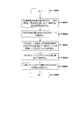
- FIG. 1 It is a schematic diagram which shows the structure which takes out the target article from a storage shelf, and stores it in a sorting shelf in a delivery gate. It is a flowchart of the process which a central control apparatus performs with respect to the structure shown in FIG. It is a schematic diagram which shows the structure which takes out the target article from the storage shelf and sorts it into another storage shelf in the delivery gate. It is a schematic diagram which shows the other structure which takes out the target article from a storage shelf, and stores it in another storage shelf in an exit gate. It is a flowchart of the process which a central control apparatus performs with respect to the structure shown in FIG. It is operation
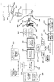
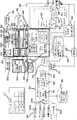
- FIG. 1 is a schematic configuration diagram of a warehouse system according to an embodiment of the present invention.
- the warehouse system 300 collects and inspects the sent-out items, and a central control device 800 (control device) that controls the whole, a warehouse 100 that stores items as stock, a buffer device 104 that temporarily stores items to be shipped, and the like.
- An aggregate inspection area 106, a packing area 107 for packing articles that have been inspected, and a loading machine 108 for posting the packed articles to a delivery truck or the like are provided.
- the warehouse 100 is an area in which a transfer robot (AGV, “Automatic” Guided “Vehicle”) described later operates, in which a storage shelf for storing articles, a transfer robot (not shown), an arm robot 200, a sensor 206, It has.
- the sensor 206 includes a camera or the like that captures an image of the entire warehouse including the transfer robot and the arm robot 200 as data.
- the arm robot 200 includes a robot body 201, a robot arm 208, and a robot hand 202.
- the robot arm 208 is a one-joint or multi-joint robot arm, and a robot hand 202 is attached to one end thereof.
- the robot hand 202 has a multi-finger shape and holds various articles.
- the robot body 201 is installed in each part in the warehouse system 300 and holds the other end of the robot arm 208.
- the article processing line by changing the article processing line between daytime and nighttime, it is possible to efficiently process the process until the article is finally conveyed through the boxing machine 108.
- the articles delivered from the warehouse 100 are temporarily stored in the buffer device 104 via the transfer line 120 such as a conveyor.
- the picked articles from other warehouses are temporarily stored in the buffer device via the transfer line 130.
- the central controller 800 determines whether or not the article in the buffer device 104 can be sent based on the detection result of the sensor 206 and the like provided in the downstream collective inspection area 106 and the like. If the determination result is “Yes”, the article stored in the buffer device 104 is taken out of the buffer device 104 and sent to the transport line 124.
- the articles sent to the aggregate inspection area 106 are detected and judged by the sensor 206.
- the worker 310 determines that inspection is necessary, the article is sent to the line where the worker 310 is located.
- the article is sent to the line of the arm robot 200 alone and inspected.
- the article is passed through the line where the worker 310 is present during this daytime time by judging the articles that are difficult to handle by the sensor 206. Thus, it becomes possible to inspect the article efficiently.
- the number of workers 310 can be reduced by inspecting the line with only the arm robot 200, and the inspection can be efficiently processed as a whole. Thereafter, the article is sent to the downstream packing area 107. Also in the packing area 107, the state of the sent article is determined by the sensor 206. Depending on the situation, the article may be, for example, a line for only small articles, a line for medium-sized articles, a line for large articles, a line for extra large articles, and a line corresponding to articles of various sizes and conditions. It is classified and sent. In each line, the worker 310 packs the article, and the packed article is sent to the posting machine 108 and waits for shipment.
- the article is passed through the line where the worker 310 is present during this daytime time by judging the articles that are difficult to handle by the sensor 206. Thus, it becomes possible to inspect the article efficiently.
- inspection can be efficiently performed as a whole by inspecting only by the arm robot 200.
- the articles delivered from the warehouse 100 are sent to the image inspection process 114 via the night conveyance line 122.
- the sensor 206 is applied to the productivity measurement of the arm robot 200 or the worker 310 at daytime or at night. In this image inspection process 114, instead of the integrated inspection area 106, it is determined one by one by the sensor 206 whether or not the target article is correctly sent from the warehouse 100.
- central controller 800 determines based on the measurement result of sensor 206 whether or not the target article can be packed by arm robot 200, in other words, whether or not packing work by worker 310 is necessary. .
- the article is sent via the transfer line 126 to the line where the worker 310 in the packing area is present.
- the package is sent to a line where the specific arm robot 200 is arranged, for example, according to the small, medium, large, or extra large shape of the article.
- the articles packed by the worker 310 and the arm robot 200 are sent to the boxing machine 108 and wait for final shipment.
- the warehouse system 300 of the present embodiment in the daytime hours when the worker's human power can be secured, goods that have a double seat shape and are difficult to handle are delivered from the warehouse. Post from the aggregate inspection area through the packing area at the discretion of the staff. On the other hand, at night when it is difficult to secure the human power of the worker, the article is transferred to the packing area 107 without going through the collective inspection area 106, centering on the article having a simple shape and easy handling. With such a configuration, the warehouse system 300 realizes efficient shipment of goods on a 24-hour basis.
- FIG. 2 is a plan view of the warehouse 100.
- the floor surface 152 of the warehouse 100 is divided by a plurality of virtual grids 612.
- Each grid 612 is affixed with a barcode 614 indicating the absolute position of the grid 612.
- FIG. 2 only one barcode 614 is shown.
- the entire floor 152 of the warehouse is divided into a plurality of zones 11, 12, 13, and the like. Each of these zones is assigned a transfer robot 602 that moves within the zone, a storage shelf 702, and the like.
- a wall 380 made of a wire mesh is formed in the warehouse 100.
- the wall 380 divides an area in which the transfer robot 602 and the storage shelf 702 move (that is, the zones 11, 12, 13 and the like) and a work area 154 where the worker 310 or the arm robot 200 (see FIG. 1) works. It has been.
- an entrance gate 320 and an exit gate 330 are formed on the wall 380.
- the warehousing gate 320 is a gate for warehousing to the storage shelf 702 etc. for goods.
- the delivery gate 330 is a gate for delivering articles from the target storage shelf 702 or the like.
- “shelf islands” configured by storage shelves 702 and the like are configured, and in this example, two “shelf islands” of 2 columns ⁇ 3 rows are configured.
- the shape and number of “shelf islands” can be arbitrarily configured.
- the transfer robot 602 can take out a target storage shelf from these “shelf islands” and move it.
- the transfer robot 602 moves the target storage shelf in front of the storage gate 320.
- the transfer robot 602 moves the storage shelf to the next target grid position. Further, at the time of delivery, the transfer robot 602 takes out a target storage shelf from “shelf island”, for example, and moves the target shelf in front of the delivery gate 330. Then, the worker 310 takes out the target article from the storage shelf.
- a square display with a crosshair indicates a shelf
- a square display with a circle at the center indicates a transfer robot 602.
- yen and the cross overlapped in the center like the storage shelf 702 in front of the delivery gate 330 shows the storage shelf supported by the conveyance robot.
- the transfer robot 602 sinks below the storage shelf, and the upper portion of the transfer robot 602 pushes up the bottom of the shelf to support the storage shelf.
- the illustrated storage shelf 702 and the like show such a state. Note that the area of the floor surface 152 of the warehouse 100 in which the transfer robot 602, the storage shelf 702, and the like are arranged can be made arbitrarily wide.
- FIG. 3 is a diagram illustrating a form of an article stored in a storage shelf.
- one article 203 is stored in one article bag 510.
- the article 203 is attached with an ID tag 402 using RFID.
- one article is stored in one article bag, but a plurality of articles may be put in one article bag, and RFID may be attached to each individual article. Is possible.
- the RFID tag 322 reads the ID tag 402 and reads the unique ID of each article. Further, instead of an ID tag using RFID, management by a barcode and a barcode scanner is also possible.
- the RFID reader 322 may be a handy type or a fixed type.
- FIG. 4 is an example of a perspective view of the transfer robot 602.
- the transfer robot 602 is an unmanned automatic traveling vehicle that travels when a wheel (not shown) at the bottom rotates.
- the collision detection unit 637 of the transport robot 602 detects the obstacle before the collision by blocking the transmitted optical signal (such as an infrared laser) by the surrounding obstacle.
- the transfer robot 602 includes a communication device (not shown).
- This communication device includes a wireless communication device that communicates with the central control device 800 (see FIG. 1), and an infrared communication unit 639 that performs infrared communication with surrounding facilities such as a charging station.
- the transfer robot 602 sinks below the storage shelf, and the upper portion of the transfer robot 602 supports the storage shelf by pushing up the bottom of the shelf. Thereby, instead of the worker himself / herself going out to the vicinity of the shelf, the transport robot 602 for transporting the shelf approaches the periphery of the worker 310, so that the picking work of the luggage on the shelf can be performed efficiently. Can do.
- the transfer robot 602 includes a camera on the bottom surface (not shown), and the camera reads the barcode 614 (see FIG. 2), so that the transfer robot 602 is located on the grid 612 where the floor robot 102 is. Recognize Then, the transfer robot 602 reports the result to the central controller 800 via a wireless communication device (not shown). Note that, instead of the barcode 614 (see FIG. 2), a LiDAR sensor or the like that measures a distance from a surrounding obstacle by a laser can be provided in the transport robot 602 and operated.
- FIG. 5 is a block diagram of the central controller 800.
- the central control device 800 includes a central processing unit 802, a database 804, an input / output unit 808, and a communication unit 810.
- the central calculation unit 802 performs various calculations.
- the database 804 stores data such as the storage shelf 702 and the article 404.
- the input / output unit 808 inputs / outputs information to / from an external device.
- the communication unit 810 performs wireless communication through a communication method such as Wi-Fi via the antenna 812, and inputs / outputs information to / from the transfer robot 602 and the like.
- the arm robot 200 is made to learn an operation pattern to be picked off-line in accordance with each transfer robot, each storage shelf, each type of container containing articles, and each shape.
- the robot arm 208 is driven using the offline data, but the sensor 206 is used to position the transfer robot, the position of the storage shelf that has moved to the picking station, and the actual arm of the arm robot. The position is detected and the correction of each position is performed in real time to correct the motion trajectory of the robot arm, and the picking of the article is performed accurately and at high speed.
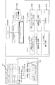
- FIG. 6 is a block diagram of a configuration relating to offline teaching and robot motion trajectory correction in the present embodiment.
- the arm robot 200 includes the robot arm 208 and the robot hand 202, and moves the article 203 by driving them.
- the transfer robot 602 moves the storage shelf 702.
- the transfer robot 602 mounts the storage shelf 702 and the like on the upper part of the main body at the shelf position 214 before transfer on the floor surface 152. Then, the transfer robot 602 moves along the transfer path 217 and moves to the shelf position 216 after transfer.
- the shelf position 216 is a position adjacent to the work area 154, that is, a position adjacent to the warehousing gate 320 or the warehousing gate 330 (see FIG. 2).
- the sensor 206 of the image camera monitors the measurement of the shelf position and the article stocker position in the shelf according to the behavior of the arm robot 200 and the transfer robot 602.
- first input data 220 is data such as a system configuration, device specifications, a robot dimension diagram, an apparatus dimension diagram, and a layout diagram.
- the first input data 220 is input to the first robot data generation unit 224 for offline robot teaching. Accordingly, the first robot data generation unit 224 generates original teaching data (not shown) based on the first input data 220.
- the second robot data generation unit 230 (robot data generation unit) is also for performing offline robot teaching.
- the original teaching data output from the first robot data generation unit 224 and the second input data 222 are input to the second robot data generation unit 230.
- the second input data 222 includes priorities, work order, restrictions, information on obstacles, work assignment rules between robots, and the like.
- the shelf position / article stocker position error calculation unit 225 calculates the position error of the movable shelf and the position error of the article stocker (a container storing a plurality of articles) based on the input information.
- the calculated position error is input to the robot position correction value calculation unit 226.
- the robot position correction value calculation unit 226 outputs a static correction value 228 indicating a static correction installation error that is effective for the first time. Further, the robot position correction value calculation unit 226 outputs a dynamic correction value 227 indicating the dynamic correction AGV repeat accuracy shelf clearance and the like.
- the static correction value 228 is input to the second robot data generation unit 230
- the dynamic correction value 227 is input to the online robot position control unit 240.
- Data from the robot teaching database 229 is also input to the second robot data generation unit 230 and the online robot position control unit 240, respectively.
- the second robot data generation unit 230 is based on the original teaching data from the first robot data generation unit 224, the second input data 222, the static correction value 228, and the data from the robot teaching database 229. Create robot teaching data.
- the created robot teaching data is input to the online robot position control unit 240.
- a signal from the online robot position control unit 240 is input to the robot controller 252.
- the robot controller 252 controls the arm robot 200 based on a signal from the online robot position control unit 240 and a command input from the teach pendant 250.
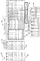
- FIG. 7 is a block diagram showing detailed configurations of the first robot data generation unit 224 and the second robot data generation unit 230 described above.
- the first input data 220 includes robot dimension drawing data 220a, apparatus dimension drawing data 220b, and layout drawing data 220c.
- the word “data” in the robot dimension diagram data 220a, the apparatus dimension diagram data 220b, and the layout diagram data 220c is omitted.
- the robot dimension diagram data 220a is data for specifying the dimensions of each part of the n arm robots 200-1 to 200-n.
- the device dimension diagram data 220b is data for specifying the dimensions of various devices included in the n arm robots 200-1 to 200-n.
- the layout diagram data 220c is data for specifying the layout of the warehouse 100 (see FIG. 2).
- the first robot data generation unit 224 includes a data capture / storage unit 261, a data reading unit 262, a three-dimensional model generation unit 263, and a data generation unit 264 (robot data generation unit).
- the above-described robot dimension diagram data 220a, apparatus dimension diagram data 220b, and layout diagram data 220c are supplied to the data capturing / storage unit 261 in the first robot data generation unit 224.
- a signal from the data capturing / storage unit 261 is input to the data reading unit 262 and also to a database 266 that stores robot dimension drawings, device dimension drawings, layout drawings, and the like.
- a signal from the data reading unit 262 is input to the three-dimensional model generation unit 263.
- the signal from the three-dimensional model generation unit 263 is input to the data generation unit 264, and the signal from the correction value capturing unit 241 is also input to the data generation unit 264.
- the original teaching data output from the data generation unit 264 is stored in the robot teaching database 229.
- the second robot data generation unit 230 includes a data reading unit 231, a teaching function 232, a data copy function 233, a work sharing function 234, a robot cooperation function 235, and a data generation unit 236 (“ Three-dimensional position (X, Y, Z)%), A robot data reading / storage unit 237, and robot controller links 238 for n arm robots 200-1 to 200-n.
- the parameter priority item restriction data 222a is a part of the second input data 222 (see FIG. 6), and is data defining various parameters, priority items, restriction items, and the like.
- the parameter priority item restriction data 222 a is input to the data reading unit 231.
- the data generation unit 236 performs coordinate calculation for obtaining the three-dimensional positions X, Y, and Z corresponding to each of the n arm robots 200-1 to 200-n, and performs robot teaching data ⁇ 1 to ⁇ 1 as original teaching data. ⁇ n is generated. Further, the data generation unit 236 calculates the correction values ⁇ 1 to ⁇ n of the robot teaching data, and based on the robot teaching data ⁇ 1 to ⁇ n as the original teaching data and the correction values ⁇ 1 to ⁇ n, each arm robot 200- The robot teaching data ⁇ 1 ′ to ⁇ n ′ supplied to 1 to 200-n are calculated.
- the robot data reading / storing unit 237 inputs / outputs data such as axis position data, operation modes, tool control data, etc., regarding the n arm robots 200-1 to 200-n with the robot teaching database 229. .
- Each of the n arm robots 200-1 to 200-n includes a robot controller 252, a robot mechanism 253, and an actuator 254 for the robot hand 202 (see FIG. 6). However, in FIG. 7, only the internal configuration of the arm robot 200-1 is shown.
- the n robot controllers 252 link with the robot controller link 238 in the second robot data generation unit 230 and input / output various signals to / from each other.
- the robot controller 252 controls the corresponding robot mechanism 253 and actuator 254.
- the sensor 206 When picking an article from the storage shelf in real time, the sensor 206 detects the relative position between the article 203 or the stocker 212 and the actuator 254. As for the detected relative position, the relative position data is output as the above-described static correction value 228 and also to the robot position correction value calculation unit 226.
- FIG. 8 is a diagram showing a control configuration for offline teaching and robot motion trajectory correction.
- the coordinate system calculation unit 290 includes a modeling virtual environment unit 280, a data capture unit 282, a coordinate calculation unit 284, a position command unit 286, and a control unit 288.
- the coordinate system calculation unit 290 handles the coordinates of the five elements described above in an absolute coordinate system.
- the coordinates of the transfer robot 602 are measured by the position sensor 207.
- the position sensor 207 a LiDAR sensor or the like that measures a distance from an object (including the transfer robot 602) existing in the vicinity may be applied.
- the operation status and position of the transfer robot 602 are controlled by the AVG controller 276.
- the position data of the robot main body 201 of the arm robot 200 is captured in advance.
- the coordinates of the robot hand 202 during the operation of the arm robot 200 are measured by a sensor such as an encoder.
- the information is supplied to the coordinate system calculation unit 290 in real time, and the position of the robot hand 202 is controlled via the robot controller 274.
- the camera included in the sensor 206 is controlled by the camera controller 272.
- the position data of the stop state of the sensor 206 is taken in by the coordinate system calculation unit 290 in advance.
- the coordinates of the sensor 206 are supplied from the camera controller 272 to the coordinate system calculation unit 290 in real time.
- the shelf information 278 is supplied to the coordinate system calculation unit 290. This shelf information 278 defines the shape and dimensions of various storage shelves 702 and the like.
- the camera included in the sensor 206 captures an image of the storage shelf 702 and the like.
- the modeling virtual environment unit 280 in the coordinate system calculation unit 290 models the storage shelf 702 and the like based on the shelf information 278 and the image of the storage shelf 702 and the like.
- the coordinate calculation unit 284 calculates the coordinates of the five elements described above based on data such as modeling results in the modeling virtual environment unit 280. Based on the calculation result of the coordinate calculation unit 284, the coordinate calculation unit 284 uses the control unit 288 to calculate, and the control unit 288 performs operations on the transfer robot 602, the robot body 201, the robot hand 202, the sensor 206, the storage shelf 702, and the like. Calculate the position command.
- FIG. 9 is a schematic diagram of absolute coordinates obtained by the coordinate calculation unit 284 (see FIG. 8).
- a transfer robot coordinate Q602, a storage shelf coordinate Q702, a sensor coordinate Q206, a robot body coordinate Q201, and a robot hand coordinate Q202 are respectively a transfer robot 602, a storage shelf 702, a sensor 206, a robot body 201, and a robot hand.
- the absolute coordinates of 202 are shown.
- the storage shelf coordinates Q702, the robot body coordinates Q201, and the robot hand coordinates Q202 are preliminarily set in various situations (for example, the type of the storage shelf 702, the type of the robot body, the type of the robot hand) by the above-described offline teaching.
- the absolute coordinates can be calculated in consideration of
- the coordinates Q201, Q202, Q206, Q602, and Q702 obtained by offline teaching are called “model values” of the coordinates.
- model values When the transfer robot 602 and the arm robot 200 are operated, the position data from the transfer robot 602, the robot body 201, the robot hand 202, and the sensor 206 are taken in, and the difference from the model value is calculated. Based on the calculated difference, real-time correction calculation is performed on the original teaching data (robot teaching data ⁇ 1 to ⁇ n) to obtain teaching data.
- offline teaching can be performed for various articles, and work efficiency (such as robot teaching) and work quality can be improved by improving positional accuracy.
- FIG. 10 is a block diagram showing a configuration for performing offline teaching of the arm robot 200 in the consolidated inspection area 106 (see FIG. 1).
- the additional calculation unit 291 includes a complementing function unit 292, a cooperative function unit 294, a group control unit 296, and a copy function unit 298.
- the additional calculation unit 291 inputs and outputs data with the coordinate system calculation unit 290.
- the coordinate system calculation unit 290 is also input with data 268 of the layout error of the robot individual. This makes it possible to create teaching data offline for the arm robot 200 in the aggregate inspection area 106. With such a configuration, offline teaching can be performed for a wider variety of articles, and work efficiency (such as robot teaching) and work quality can be improved due to improved position accuracy.
- the configuration shown in FIG. 10 can also be applied to the arm robot 200 in the packing area 107.
- FIG. 11 is a block diagram of another configuration for performing offline teaching of the arm robot 200 in the consolidated inspection area 106 (see FIG. 1).
- a deep learning processing unit 269 is provided in addition to the configuration shown in FIG. 10.
- the deep learning processing unit 269 exchanges data with each other to the coordinate system calculation unit 290 and the additional calculation unit 291 to perform artificial intelligence processing by deep learning.
- offline teaching can be performed for a wider variety of articles, and work efficiency (such as robot teaching) and work quality can be improved due to improved position accuracy.
- the configuration shown in FIG. 11 can also be applied to the arm robot 200 in the packing area 107.
- the storage shelf coordinate model value (Q702) which is the model value of the three-dimensional coordinates of the storage shelf (702), and the three-dimensional of the robot hand (202).
- a robot teaching database (229) for storing robot hand coordinate model values (Q202) which are coordinate model values and original teaching data (robot teaching data ⁇ 1 to ⁇ n) which are teaching data of the arm robot (200) based on A sensor (206) for detecting the relative positional relationship between the storage shelf (702) and the robot hand (202), and correcting the original teaching data based on the detection result of the sensor (206), thereby enabling the arm robot (200).
- a robot data generation unit (264, 230) for generating robot teaching data ( ⁇ 1 ′ to ⁇ n ′) to be supplied to.
- the original teaching data (robot teaching data ⁇ 1 to ⁇ n) is stored in the sensor (206) in addition to the storage shelf coordinate model value (Q702) and the robot hand coordinate model value (Q202).
- a sensor coordinate model value (Q206) that is a model value of three-dimensional coordinates, a transport robot coordinate model value (Q602) that is a model value of three-dimensional coordinates of the transfer robot (602), and a three-dimensional coordinate of the robot body (201) Is the teaching data of the arm robot (200) based on the robot body coordinate model value (Q201) which is the model value of
- offline teaching can be performed corresponding to various articles, and work efficiency and work quality can be improved by improving position accuracy.
- the inventory status of each article can be managed accurately.
- the warehouse system 300 can simulate the transfer robot 602 and the arm robot 200 to execute an efficient work sequence, and can efficiently control the transfer robot and the arm robot in each zone. To realize.
- FIG. 12 is a flowchart of the simulation process in each zone, which is executed by the central controller 800 (see FIG. 1).
- the simulation in the zone is performed before the actual picking system is operated.
- This simulation includes (1) establishment of an autonomous operation sequence of the transfer robot (steps S105 to S107) and (2) simulation in the shelf of the arm robot (steps S108 to S110).
- step S101 when the process starts in step S101, the process proceeds to step S102, and the central controller 800 simulates the plan of the entire system as a warehouse system.
- step S103 the central controller 800 receives data such as the inventory amount in the shelf as a parameter.
- step S104 the central controller 800 starts a simulation within the zone. Thereafter, the processes of steps S105 to S107 and the processes of steps S108 to S110 are executed in parallel.
- step S105 the central controller 800 determines a work sequence for the transfer robot. That is, the operation sequence in the corresponding zone is determined.
- step S106 the central controller 800 performs coordinate calculation and coordinate control for the transfer robot.
- step S ⁇ b> 107 the central controller 800 performs operation control with respect to the transfer robot.
- the central controller 800 performs a simulation in the shelf with respect to the arm robot. In other words, the work sequence is determined. At that time, the central controller 800 performs an in-shelf simulation by utilizing an off-line teach technique. Next, when the process proceeds to step S109, the central controller 800 performs coordinate calculation and coordinate control for the arm robot. Next, when the process proceeds to step S110, the central controller 800 performs operation control on the arm robot.
- specific two-dimensional coordinates 111 are set in advance for the two-dimensional coordinates in the zone. Furthermore, as the shelf information 113 related to a specific article, which storage shelf the storage shelf belongs to, which two-dimensional address in the zone, which storage shelf belongs to, which storage shelf Is set to the position of.
- FIG. 13 is an explanatory diagram of the transfer robot work sequence as a result of the zone-based autonomous control simulation.
- the order list data 458 is received as an order 452 for an article (article) to the warehouse system 300 (see FIG. 1).
- the shipment list data 460 is confirmed as the shipment 454 to be shipped from the warehouse system, the premise of the plans in the zones of the zones 11, 12, and 13 and the constraint data 468 are determined, and this is taken into consideration. To do.
- the autonomous control simulation of the transfer robot when the storage shelf is moved and taken out from each zone by the transfer robot, the movement distance, the number of movements, etc. of the transfer robot are considered as objective functions. Then, it is shown that it is efficient to pick the target article as much as possible from the zone 11 surrounded by the dotted line.
- FIG. 14 is an explanatory diagram of an off-line teaching operation of the arm robot 200.
- a control computer 474 in which dedicated software for offline teaching is installed is provided.
- the database 476 stored in the control computer 474 stores (1) points, (2) paths, (3) operation modes (interpolation types), (4) operation speeds, and (5) hand postures as teach data. (6) Work conditions are provided.
- the arm robot 200 is caused to perform learning using the dedicated control device 470 and the teach pendant 472.
- learning is performed offline so as to improve work efficiency by setting the movement distance, the number of movements, and the like of the robot arm 208 and the robot hand 202 as objective functions.
- learning is performed offline so as to improve work efficiency by setting the movement distance, the number of movements, and the like of the robot arm 208 and the robot hand 202 as objective functions.
- it is learned off-line how to efficiently move the robot hand 202 from which opening and how.
- FIG. 15 is a block diagram of another configuration of offline teaching and robot motion trajectory correction in the present embodiment. 15, the same reference numerals as those in the example described in FIG. 6 have the same configuration and effects unless otherwise specified.
- the configuration of FIG. 15 includes an AGV controller 276 and a second robot data generation unit 230 ⁇ / b> A (robot data generation unit) instead of the second robot data generation unit 230. Further, the third input data 223 is supplied to the second robot data generation unit 230A.
- the third input data 223 includes (1) zone information, (2) shelf information, (3) work sequence determination conditions, and the like. Further, the AGV controller 276 establishes (1) an autonomous operation sequence of the transfer robot 602 and (2) an operation sequence based on an in-shelf simulation of the arm robot 200, and performs control operations of the transfer robot 602 in real time. Realized.
- FIG. 16 is a block diagram showing a detailed configuration of the second robot data generation unit 230A in FIG.
- the same reference numerals as those in the example described in FIG. 7 have the same configuration and effects unless otherwise specified.
- the second input data 222 and the third input data 223 are input to the second robot data generation unit 230A.
- operation result data 354 is also input to the second robot data generation unit 230A.
- the operation result data 354 is data representing the results of entering and leaving various articles.
- the second input data 222, the third input data 223, and the operation result data 354 are read by the second robot data generation unit 230A via the data reading units 231, 356, and 358, respectively.
- the second robot data generation unit 230A includes an overall system simulation unit 360 and an in-zone simulation / in-shelf simulation unit 362.
- the entire system simulation unit 360 and the in-zone simulation / in-shelf simulation unit 362 input / output data to / from the simulation database 366, and finally the work sequence determination unit 364 is connected to the transfer robot 602.
- the entire control sequence including the arm robot 200 is determined. With these configurations, (1) an autonomous operation sequence of the transfer robot 602 and (2) an operation sequence based on an in-shelf simulation of the arm robot 200 are established to realize a high-speed and highly accurate control operation. Yes.
- FIG. 17 is a flowchart of processing executed by the second robot data generation unit 230A.
- the second robot data generation unit 230A creates a model of the warehouse system 300.
- the second robot data generation unit 230A determines that the model previously generated in step S201 and the second input data 222 (priority, work order, restrictions, obstacle information, The simulation of the entire warehouse system 300 is performed based on the inter-robot work sharing rules and the like.
- the second robot data generation unit 230A is based on the simulation result in step S203 and the third input data 223 (zone information, shelf information, work sequence determination conditions, etc.). Execute the simulation in the zone.
- the second robot data generation unit 230A performs an in-shelf simulation.
- the second robot data generation unit 230A performs the work based on the in-shelf simulation result in step S206 and the operation result data 354 (results of entering / exiting various articles). Determine the sequence.
- the second robot data generation unit 230A executes coordinate calculation, various controls, and the like based on the processing results of steps S201 to S208. Accordingly, the second robot data generation unit 230A can perform a simulation on the transfer robot 602 and the arm robot 200 in the warehouse system 300 and execute an efficient work sequence. Thereby, the transfer robot 602 and the arm robot 200 can be efficiently controlled in each zone.
- each is assigned to one of the zones (11, 12, 13), and from the assigned zone (11, 12, 13), the arm robot ( 200), when a transport robot (602) that transports the storage shelf (702) together with the article (203) and any article (203) as a delivery target are designated, the respective zones (11, 12) are designated. , 13), a control unit (800) that performs a simulation when the article is delivered (S104), and determines a zone (11, 12, 13) in which the article (203) is delivered based on the simulation result; Is provided.
- the control device (800) has the smallest moving distance or number of movements of the transfer robot (602) among the plurality of zones (11, 12, 13) based on the simulation result. Is determined as a zone (11, 12, 13) in which the goods (203) is discharged. Thereby, in each zone (11,12,13), the transfer robot (602) and the arm robot (200) can be controlled efficiently.
- a technique for predicting line box retention in the integrated inspection area 106 or the packing area 107 of the warehouse system 300 will be described.
- a sensor 206 including a camera is installed at a required place on the conveyor line, and the staying state of the flowing container is measured.
- the central control device 800 detects a sign of congestion on the conveyor, the central control device 800 can notify the information terminal (smart phone, smart watch, etc.) of the worker 310 in real time before actually staying, thereby promoting the countermeasure. Details will be described below.
- FIG. 18 is a block diagram of the analysis processing apparatus 410 included in this embodiment.
- the analysis processing device 410 may be a separate device from the central control device 800, or may be a device integrated with the central control device 800.
- the analysis processing device 410 includes a feature amount extraction unit 412, a feature amount storage unit 414, a difference comparison unit 416, a threshold setting unit 418, an abnormality determination processing unit 420, an abnormality report processing unit 422, and an analysis unit 428. And a feedback unit 430 and an abnormality occurrence prediction unit 432.
- Image data from the sensor 206 is sent to the feature amount extraction unit 412 of the analysis processing apparatus 410. Then, the image data is sent to the feature amount storage unit 414 and then compared with a reference image (to be described later) by the difference comparison unit 416. Thereafter, data is sent to the threshold setting unit 418, and the abnormality determination processing unit 420 determines the degree of deviation from the threshold. The determination result in the abnormality determination processing unit 420 is supplied to the abnormality notification processing unit 422, and the supplied information is displayed on the abnormality occurrence display device 424.
- other information 426 is supplied from the outside to the analysis unit 428 in order to set a threshold value and the like.
- the other information 426 is information such as the order quantity on the day, the handling item category on the day, the number of workers, the camera installation position, the conveyor position, and the like.
- Data from the analysis unit 428 is supplied to the feedback unit 430.
- the threshold setting unit 418 sets a threshold based on the information supplied to the feedback unit 430.
- the data from the feature amount storage unit 414 is also supplied to the analysis unit 428. Further, the determination result in the abnormality determination processing unit 420 is also input to the analysis unit 428.
- the analysis data from the analysis unit 428 is sent to the abnormality occurrence prediction unit 432, and also sent to other external planning system / control device 436 for use.
- the abnormality occurrence display device 424 can be notified of the occurrence of the abnormality.
- the abnormality occurrence display device 424 for notifying the occurrence of abnormality may be, for example, a warning light (not shown) in the warehouse system, a smartphone of the worker 310, a smart watch, or the like.
- the abnormality occurrence prediction unit 432 supplies data indicating the fact to the prediction information display device 434.
- the prediction information display device 434 can display a prediction status such as “estimated occurrence of stagnation within ⁇ minutes”, for example.
- a smartphone, smart watch, or the like of the worker 310 can be applied to the prediction information display device 434 that displays the prediction status.
- FIG. 19 is a schematic diagram showing the operation of the analysis processing apparatus 410 in the present embodiment.
- a box-shaped container 560 (conveyance target) is applied as an example of the conveyance object.
- an image in a state of nothing (not operating) is captured by the sensor 206 on the transport line 124.
- This image is referred to as a reference image 562.
- the feature amount of the reference image 562 is stored in the difference comparison unit 416 (see FIG. 18).
- the acquired image on the transport line 124 when the warehouse system 300 is actually operating is captured from the sensor 206.
- This image is referred to as an acquired image 564.
- the feature quantity extraction unit 412 extracts the feature quantity of the acquired image 564, and the extracted feature quantity is stored in the feature quantity storage unit 414 and then supplied to the analysis unit 428.
- the image of the conveyance line 124 after n seconds is captured by the sensor 206.
- the image data at this time is also sent to the analysis unit 428, and thresholds th1 and th2 (not shown) for determining the occurrence of abnormality are obtained.
- the threshold value th1 is a threshold value for determining whether or not there is a possibility that the conveyance line 124 starts to be crowded
- the threshold value th2 is a threshold value for determining whether or not an abnormality has occurred. Accordingly, there is a relationship of “th1 ⁇ th2” between the two threshold values.
- the threshold th1 is “1” and the threshold th2 is “3”.
- the number of container images is equal to or less than the threshold th1, and thus the analysis processing apparatus 410 determines “no abnormality”.
- the number of container images is “1”. In this case as well, the number of container images is equal to or less than the threshold th1, and thus the analysis processing apparatus 410 determines “no abnormality”.
- the analysis processing apparatus 410 determines that “abnormality has occurred (the container 560 is retained)”. To do. In this case, as described above, the analysis processing device 410 blinks a warning light (not shown) in the warehouse system 300, and further notifies the smartphone 310, the smart watch, etc. of the worker 310 of the occurrence of the retention abnormality. . In this case, the transfer line 124 may be forcibly stopped.
- the worker 310 reduces the amount of the container 560 that flows to the line of the robot main body 201, and many containers 560 flow to the line where the worker 310 is present. It is good to switch control as follows. Further, in order to avoid staying, the process of flowing the container 560 to another transfer line may be instructed by the central controller 800 without waiting for an instruction from the worker 310 or the like.
- a plurality of transfer lines 120, 122, 124, 126, 130 each carrying the transfer object (560) and one transfer line.
- the sensor (206) that detects the state of the sensor and the sensor (206) determines that one transport line is congested, the operator is requested to transport the transport object (560) to another transport line.
- an analysis processing device (410) that performs notification.
- the analysis processing device (410) when the amount of the transport object (560) exceeds the first threshold value (th1), the analysis processing device (410) notifies the operator of the fact, and the transport object (560). ) Exceeds a second threshold (th2) greater than the first threshold (th1), the corresponding transfer line (124) is stopped. Thereby, the worker can reliably detect the stay of the conveyance object (560), and can quickly take measures such as a change of the line.
- FIG. 20 is a schematic diagram illustrating a method for inspecting an article to be stored using the transfer robot 602 in the warehouse system 300.
- a storage shelf 702 and the like are arranged in each zone 11, 12, 13, and the like in the warehouse 100.
- a box in which goods are packed for example, a cardboard box
- a dining table-shaped load receiving base 852 as shown in FIG. 20 can be applied.
- the pallet pedestal 852 may be a pallet.
- the transfer robot 602 can support and move the load receiving pedestal 852 by sinking under the load receiving pedestal 852 and pushing up the upper plate 852a of the load receiving pedestal 852.
- FIG. 21 is a block diagram of an inspection system 270 applied to inspection work in the warehouse system 300.
- the inspection system 270 includes an AGV controller 276, a transfer robot 602, a control device 860, an illumination device 858, a sensor 206, and a laser device 856.
- the control device 860 may be a separate device from the central control device 800 or may be an integrated device with the central control device 800.
- the transfer robot 602 moves or rotates the load receiving base 852 on which the load receiving article 854 (see FIG. 20) is loaded based on a command from the AGV controller 276.
- the command from the AGV controller 276 is also supplied to the control device 860, and the sensor 206 such as a camera operates based on this command to image the consignment article 854.
- the control device 860 uses the illumination device 858 to irradiate the receiving article 854 with strobe light, and uses the laser device 856 to apply red lattice light (red lattice laser light) to the receiving article 854. Irradiate. If the receiving article 854 is a rectangular parallelepiped object such as a cardboard box, for example, a red lattice image is projected on the receiving article 854 by the red grating light.
- the inspection system 270 it is possible to automatically execute inspection of the consigned article 854 in the middle of a line for conveying the consigned article 854 by the transport robot 602.
- the inspection system 270 includes both the laser device 856 and the illumination device 858, but only one of them may be provided.
- the sensor 206 can take an image of the received article 854, and the product name, the product code, the number of pieces, the expiration date, the lot number, and the like described on the surface of the received article 854 are related.
- a bar code or a two-dimensional code associated with information, or a product label or a shipping label on which these are written is read.
- the control device 860 can perform inspection work of the inspection system 270 based on the read information.
- the sensor 206 is not limited to the camera, and may be, for example, an RFID reader or the like, and the shipment inspection may be performed in the same manner by reading the information of the RFID tag attached to the consignment article 854.
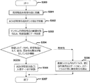
- FIG. 22 is a flowchart of the inspection process executed by the control device 860.
- the process starts in step S300 of FIG. 22, the process proceeds to step S301, and the consignment article 854 is mounted on the consignment pedestal 852. That is, the goods receiving article 854 conveyed from the outside by a truck or the like is placed on the conveyor 304 or the like and then sent to the upper part of the goods receiving base 852. In general, a plurality of goods receiving articles 854 are mounted on the goods receiving pedestal 852.
- step S ⁇ b> 302 the transfer robot 602 moves the load receiving base 852 to the front of the sensor 206 under the control of the control device 860. That is, the transfer robot 602 sinks below the load receiving pedestal 852 and lifts the load receiving article 854 including the load receiving pedestal 852. Then, in the state of being placed on the cargo receiving pedestal 852, the cargo receiving article 854 is conveyed to a place where it can be photographed by the image camera of the sensor 206.
- step S ⁇ b> 303 the transfer robot 602 rotates 360 degrees in front of the sensor 206 in response to a command from the control device 860.
- the sensor 206 captures an image of the consignment article 854 at that time and transmits it to the control device 860.
- step S304 the control device 860 determines whether an abnormality (scratch, discoloration, distortion, etc.) has occurred in the consignment article 854 based on the captured image.
- step S304 If the determination result in step S304 is “no abnormality”, the process proceeds to step S305.
- the transfer robot 602 moves to the warehousing gate 320 (see FIG. 2) together with the cargo receiving pedestal 852.
- step S306 control device 860 turns on a warning light (not shown) in warehouse system 300. Further, the control device 860 notifies the information terminal (smart phone, smart watch, etc.) of the worker 310 that an abnormality has occurred, and moves the consignment pedestal 852 and the consignment article 854 to a different location from the warehousing gate 320.
- the dining table-shaped load receiving base (852) having the upper plate (852a), and the inspection object placed on the upper plate (852a) ( 854) a sensor (206) that detects the state of the load receiving base (852), and a robot (602) that supports and moves the load receiving base (852) by pushing up the upper plate (852a) by sinking under the load receiving base (852).
- the conveyance robot (602) supporting the load receiving base (852) is moved in the horizontal direction on condition that the inspection object (854) is within a range in which the inspection object (854) can be inspected by the sensor (206).
- a control device (860) for rotating the device for rotating the device.
- the irradiation apparatus (858,856) which irradiates light with respect to a test target object (854), and a control apparatus (860) irradiates light to a test target object (854).
- the state of the inspection object (854) is determined based on the result. Thereby, the presence or absence of abnormality of the inspection object (854) can be detected with high accuracy.
- FIG. 23 is a plan view of the zone 12 for explaining an efficient arrangement of the storage shelves.
- an island 750 is formed in the zone 12, and a storage shelf 720 is included therein.
- Other configurations of the zone 12 are the same as those shown in FIG.
- an island having six storage shelves such as storage shelves 732 and 742 is referred to as “island 751”
- an island having six storage shelves such as storage shelves 712 and 714 is referred to as “island 752”.
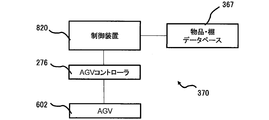
- FIG. 24 is a block diagram of a storage shelf replacement system 370 applied to storage shelf replacement processing in the warehouse system 300.
- the storage shelf replacement system 370 includes a control device 820, an AGV controller 276, a transport robot 602, and an article / shelf database 367.
- the control device 820 may be a separate device from the central control device 800, or may be a device integrated with the central control device 800.
- the article / shelf database 367 stores article delivery probability data representing the delivery probability of various articles 203 and storage shelf delivery probability data representing the delivery probability of each storage shelf.
- the control device 820 determines a pair of storage shelves for replacement by referring to the article / shelf database 367.
- the determined storage shelves are the storage shelf 716 (first storage shelf) and the storage shelf 720 (second storage shelf) in the example shown in FIG. Then, the control device 820 instructs the AGV controller 276 of the determined pair of storage shelves, and causes both storage shelves to be replaced.
- FIG. 25 is a flowchart of a shelf arrangement routine executed by the control device 820.
- the control device 820 accumulates statistical data on the delivery status of the article 203 (see FIG. 3) in a specific zone (zone 12 in the example shown in FIG. 23) in the warehouse 100 over a predetermined sample period. To do.
- step S402 the control device 820 performs a statistical process on the statistical data, and selects an article 203 with a high delivery frequency based on the result.
- step S403 the control device 820 selects a storage shelf with a high delivery frequency (hereinafter referred to as a high-frequency storage shelf) in which the selected article 203 is stored.
- the storage shelf 720 is a high-frequency storage shelf.
- the process of step S403 simply selects an article 203 with a high delivery probability predicted in a future period as well as a high delivery frequency of the article based on a specific past sample period. It is preferable.
- a future issue frequency is calculated in consideration of the future season, weather, temperature, month, day, fashion, etc., and based on the result, an article 203 with a high output probability is selected, and The high-frequency storage shelf in which the article 203 is stored may be selected.
- step S ⁇ b> 404 the article 203 stored on the island close to the exit gate 330 (the island closest to the exit gate 330 or the island within a predetermined distance from the exit gate 330). Select an item with a low delivery frequency. Furthermore, in step S404, a storage shelf (hereinafter referred to as a low frequency storage shelf) in which articles with a low delivery frequency are stored is specified. In the example shown in FIG. 23, the low-frequency storage shelf is the storage shelf 716.
- step S405 the control device 820 outputs a command to the transfer robot 602, takes out the low-frequency storage shelf from the current island, and moves it from the exit gate 330 to a far island.
- the storage shelf 716 that is a low-frequency storage shelf is taken out from the island 752 and moved to the island 750 that is away from the shipping gate 330.
- step S ⁇ b> 406 the control device 820 outputs a command to the transfer robot 602, takes out the high-frequency storage shelf from the current island, and moves it to the island near the shipping gate 330.
- the storage shelf 720 that is a high-frequency storage shelf is taken out from the island 750 and moved to the island 752 near the shipping gate 330.
- a storage shelf storing articles that are likely to be taken out can be arranged in the vicinity of the delivery gate 330. Thereby, the moving distance of the storage shelf by the transfer robot 602 can be shortened, and the time required for picking the article 203 can be shortened.
- the storage shelves may be replaced by operating the transport robot 602 across all zones.
- a plurality of storages for storing a plurality of articles (203) that are respectively arranged at predetermined locations on the floor surface (152) and that can be delivered.
- any one of the shelves (716, 720) and the plurality of articles (203) is designated, any one of the storage shelves (716, 720) for storing the designated article (203) is placed at a predetermined position.
- a plurality of storage shelves (716, 720) are provided to the delivery gate (330) on the basis of the transfer robot (602) that transports to the delivery gate (330) provided in the past and the results of shipment of a plurality of articles (203) in the past.
- the frequency predicted for the second storage shelf (720) is higher than the frequency predicted for the first storage shelf (716) among the plurality of storage shelves (716, 720). High and first storage If the location of the second storage shelf (720) is further than the delivery gate (330) than the location of (716), the second storage shelf ( And a control device (800) for changing the arrangement location of the first storage shelf (716) or the second storage shelf (720) so that the arrangement location of 720) is close to the delivery gate (330).
- the control device (800) when changing the location of the first storage shelf (716) or the second storage shelf (720), changes the first storage shelf (716). Are replaced with the second storage shelf (720).
- a storage shelf storing articles that are likely to be taken out can be arranged in the vicinity of the exit gate, and the moving distance of the storage shelves by the transfer robot (602) can be shortened. The time required can be shortened.
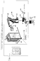
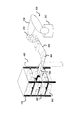
- FIG. 26 is a schematic diagram of a configuration in which the bucket 480 (baguette) is taken out from the storage shelf in the warehouse system 300.
- the bucket 480 is a box placed on each shelf in the storage shelf, and has a substantially rectangular parallelepiped shape with an open upper surface.
- the bucket 480 generally stores a plurality of articles 203 of the same type (see FIG. 3).
- the bucket 480 is taken out from the storage shelf 702 or the like, it can be considered that the bucket 480 is picked and pulled out by the robot hand 202 of the arm robot 200.
- the arm robot 200 includes one robot arm 208 and one robot hand 202.
- a configuration using two robot arms 208 and two robot hands 202 is also conceivable. That is, it is conceivable that the bucket 480 is pulled out by one of the two robot arms 208 and the article 203 is taken out of the bucket 480 by the other robot arm 208.
- it takes time to control the robot arm 208 it has been difficult to realize high-speed extraction of the article 203 with any of the above-described techniques.
- a stacker crane 482 is provided as means for taking out the bucket 480 from the storage shelf 702.
- the stacker crane 482 has a drawer arm 486 for carrying out and carrying in the bucket 480 from a shelf such as the storage shelf 702, and a function of causing the drawer arm 486 to travel in the left-right direction with respect to the opposing surface of the storage shelf 702, And a function to raise and lower the extraction arm 486 in the vertical direction.
- the stacker crane 482 is provided at the delivery gate 330 (see FIG. 2).
- the transfer robot 602 moves the storage shelf 702 storing the target article to the front of the delivery gate 330.
- the buckets 480 stored in the storage shelf 702 are classified into specific types. Therefore, the stacker crane 482 can specify the bucket to be pulled out in accordance with the instruction from the central controller 800. Thereby, compared with the case where the robot arm 208 is driven, the bucket 480 can be pulled out from the storage shelf 702 at high speed and accurately.
- FIG. 27 is a schematic diagram of another configuration for taking out the bucket 480 from the storage shelf in the warehouse system 300.
- a buffer shelf 484 for temporarily storing the bucket 480 taken out by the stacker crane 482 is provided. That is, the bucket 480 taken out by the stacker crane 482 is temporarily stored in the buffer shelf 484. Then, the arm robot 200 picks the article 203 from the bucket 480 placed on the buffer shelf 484.
- the bucket 480 necessary for picking (for example, a plurality of buckets) 480 is stored in the buffer shelf 484 as compared with the one shown in FIG. Can do.
- the picking work time by the arm robot 200 varies depending on the type and situation of the target article 203, the picking work time by the robot arm 208 is made uniform by temporarily holding the bucket 480 on the buffer shelf 484. Can be planned.
- FIG. 28 is a flowchart of processing executed by the central controller 800 (see FIG. 1) for the configuration shown in FIG.
- the central controller 800 retrieves the article 203 to be delivered from the article data of the article stored in the warehouse 100, the storage shelf 702 in which the target article is stored, and the article 203 in the storage shelf. The position of is specified.
- the central control device 800 moves the storage shelf 702 or the like containing the articles 203 to the delivery gate 330 by the transfer robot 602.
- step S503 when the process proceeds to step S503, the central controller 800 controls the stacker crane 482 to move the drawer arm 486 to the position of the bucket 480 in which the target article 203 is stored, and the target bucket 480. Pull out.
- step S504 when the process proceeds to step S504, the stacker crane 482 moves the target bucket 480 to the buffer shelf 484 under the control of the central controller 800.
- step S ⁇ b> 505 the arm robot 200 takes out the target article 203 from the bucket 480 of the buffer shelf 484 using the robot arm 208 and the robot hand 202 based on a command from the central controller 800. Issue.
- FIG. 28 is a flowchart for the configuration of FIG. 27, but for the configuration of FIG. 26, step S504 may be skipped, and other processing is the same as that described above.
- the operation of taking out the bucket 480 from the storage shelf 702 or the like is executed by the stacker crane 482 instead of the robot arm 208. Picking can be performed at higher speed.
- the bucket (480) for storing the article (203) and the floor (152) are respectively arranged at predetermined locations, and each is discharged.
- the bucket (480) for storing the article (203) is designated from the stacker crane (482) to be taken out from the storage shelf (702) and the bucket (480) taken out by the stacker crane (482). It includes an arm robot (200), a retrieving article a (203).
- FIG. 27 further has a buffer shelf (484) holding the bucket (480) taken out by the stacker crane (482), and the arm robot (200) is held by the buffer shelf (484).
- the article (203) is taken out from the bucket (480) that has been used.
- picking can be performed at high speed by taking out the article (203) from the storage shelf (702) by the stacker crane (482).
- FIG. 29 is a schematic diagram showing a configuration in which a target article is taken out from the storage shelf 702 and the like and stored in the sorting shelf 902 in the delivery gate 330 (see FIG. 2).
- the sorting shelf 902 sorts articles for each shipping destination.
- two parallel rails 492 are laid on the floor surface.
- the robot main body 201 includes wheels placed on the rails 492 and a motor that drives the wheels (not shown). Thereby, the robot body 201 can move along the rail 492.
- the storage shelf 702 stores a bucket 480 in which a target article 203 is stored.
- the arm robot 200 moves the robot arm 208 to a position facing the bucket 480. Thereby, the arm robot 200 can pick an article with high work efficiency and move the target article to the sorting shelf 902.
- FIG. 30 is a flowchart of processing executed by central controller 800 for the configuration shown in FIG.
- the process starts in step S600 of FIG. 30, the process proceeds to step S601.
- the central controller 800 retrieves the article 203 to be delivered from the article data of the article stored in the warehouse 100, the storage shelf 702 in which the target article is stored, and the article 203 in the storage shelf. The position of is specified.
- the central controller 800 moves the specified storage shelf 702 and the like to the delivery gate 330 using the transfer robot 602.
- step S603 when the process proceeds to step S603, the robot main body 201 moves on the rail 492 to a position where the robot arm 208 and the robot hand 202 can easily take out the target article 203 under the control of the central controller 800.
- step S604 when the process proceeds to step S604, the arm robot 200 pulls out the bucket 480 and takes out the target article 203 using the robot arm 208 and the robot hand 202 under the control of the central controller 800.
- step S605 when the process proceeds to step S605, the central controller 800 moves the robot main body 201 on the rail 492 so as to store the taken-out article in a predesignated shelf position of the sorting shelf 902.
- step S ⁇ b> 606 the arm robot 200 stores the taken-out article at a predesignated shelf position of the sorting shelf 902 under the control of the central controller 800.
- the arm robot 200 pulls out the bucket 480.
- the stacker crane 482 is provided to store the target article. May be pulled out by the stacker crane 482.
- FIG. 31 is a schematic diagram showing a configuration in which a target article is taken out from the storage shelf 702 and the like and sorted into other storage shelves 722 and 724 (sorting shelves) in the delivery gate 330 (see FIG. 2).
- the robot main body 201 moves on the two rails 492.
- storage shelves 722, 724 and the like are applied instead of the sorting rack 902. That is, the transfer robot 602 moves the storage shelves 722 and 724 to the operation range of the arm robot 200 as necessary.
- the articles 203 taken out from the bucket 480 of the storage shelf 702 are stored in the storage shelf 722. 724 bucket 480. That is, in the storage shelves 722 and 724, the article 203 can be stored in the bucket 480 in the range of the opening of the bucket 480 placed on the surface facing the arm robot 200.
- the transfer robot 602 rotates the storage shelves 722 and 724, and stores articles or the like in the buckets 480 on the opposite side. Make it stowable. Further, when there is no empty space in the openings of all the buckets 480 of the storage shelves 722 and 724, the transfer robot 602 moves another new storage shelf (not shown) to the operation range of the arm robot 200. Thereby, goods etc. can be similarly stored in a new storage shelf.
- the storage shelves 722, 724 and the like function as a sorting shelf.
- FIG. 32 is a schematic diagram showing another configuration in which a target article is taken out from the storage shelf 702 or the like and stored in other storage shelves 722 and 724 in the shipping gate 330 (see FIG. 2).
- the example shown in FIG. 32 is different in that the transfer robot 602 finely drives the storage shelves 722 and 724 that function as sorting shelves. That is, the transfer robot 602 finely moves the storage shelves 722 and 724 in units of width such as the bucket 480 in accordance with the location of the bucket 480 that stores the target article.
- the central controller 800 determines which bucket 480 of the storage shelves 722 and 724 is to put the target article. To do. Then, the transfer robot 602 moves the storage shelves 722 and 724 left and right in units of the width of the bucket 480 so that the position of the bucket 480 and the movable position of the robot hand 202 are matched. Accordingly, the distance that the robot arm 208 and the robot hand 202 move can be shortened, and the process of storing articles picked from the storage shelf 702 in the storage shelves 722 and 724 can be executed at high speed.
- FIG. 33 is a flowchart of processing executed by the central controller 800 for the configuration shown in FIGS. 31 and 32.
- the central controller 800 retrieves the article 203 to be delivered from the article data of the article stored in the warehouse 100, the storage shelf 702 in which the target article is stored, and the article 203 in the storage shelf. The position of is specified.
- the central controller 800 moves the specified storage shelf 702 and the like to the delivery gate 330 using the transfer robot 602.
- the arm robot 200 uses the robot arm 208 and the robot hand 202 to pull out the bucket 480 from the storage shelf 702 and remove the target article 203. Take out.
- the transfer robot 602 moves the sorting storage shelves 722 and 724 to the sorting position of the delivery gate 330 under the control of the central controller 800. More specifically, the transfer robot 602 is configured in units of the width of the bucket 480 so that the robot arm 208 and the robot hand 202 can easily store the target articles in the storage racks 722 and 724 for sorting. The storage shelves 722 and 724 are moved.
- step S ⁇ b> 705 the arm robot 200 stores the articles in the buckets 480 at the shelf positions designated in advance in the sorting storage shelves 722 and 724 under the control of the central controller 800.
- step S706 the central controller 800 determines whether or not it is necessary to additionally add a target article to the sorting storage shelves 722 and 724. If this determination result is affirmative (added), the process returns to step S701, and the same operation as described above is repeated. On the other hand, if this determination result is negative (no addition), the storage shelf 702 is moved from the sorting position.
- the arm robot 200 pulls out the bucket 480.
- a stacker crane 482 is provided to store a target article.
- the stacked bucket 480 may be pulled out by the stacker crane 482.
- the arm robot 200 may take out articles from the bucket 480 after the pulled bucket 480 is moved to the buffer shelf 484 (see FIG. 27).
- step S704 described above the sorting storage shelves 722 and 724 are moved in units of bucket widths using the transfer robot 602. However, if the arm robot 200 is capable of operating at high speed, it is shown in FIG. As described above, the articles may be stored in the storage shelves 722 and 724 while the sorting storage shelves 722 and 724 are fixed.
- a moving device (201, 602) for moving the arm robot (200) or the sorting shelves (722, 724) so as to reduce the distance.
- the moving device (602) sinks below the sorting shelf (722, 724) and pushes up the sorting shelf (722, 724) to thereby sort the shelf (722, 724).
- FIG. 34 is an operation explanatory diagram when the transfer robot 602 detects an obstacle.
- the worker 310 is an obstacle is shown.
- members having the same reference numerals as those shown in FIGS. 1 to 33 described above have the same configuration and effects as those shown in FIGS. 1 to 33.
- a sensor 206 such as a camera is arranged on the ceiling, and the state of the transfer robot 602 and its surroundings is monitored.
- the following virtual areas 862, 864, and 866 are located in front of the moving direction. It is set. (1) Area 866 from 5 m ahead to 3 m ahead of transfer robot 602 (2) Area 864 from 3 m ahead to 1 m ahead of transfer robot 602 (3) Area 862 within 1 m ahead of transfer robot 602
- FIG. 35 is a schematic diagram when a plurality of transfer robots 602 move along different paths 882 and 884, respectively.
- two transfer robots 602 are moving along paths 882 and 884 which are separate routes.
- the paths 882 and 884 are paths assumed on the floor surface, and the paths 882 and 884 are not physically formed particularly on the floor surface.
- the central controller 800 sets virtual regions 872 and 874 for each transfer robot 602, controls the operation state of each transfer robot 602, and avoids collision with an obstacle (such as a worker 310). is doing. In the example shown in FIG. 35, two transfer robots 602 are applied, but the number of transfer robots 602 may be three or more.
- FIG. 36 is a flowchart of processing executed by the central controller 800 in order to avoid a collision between an operator 310 and the like and an obstacle.
- the central control device 800 sets the following three virtual areas with respect to the moving direction of the transfer robot 602 in order to avoid a collision between the worker 310 and the like and an obstacle. (1) Area 866 from 5 m ahead to 3 m ahead of transfer robot 602 (2) Area 864 from 3 m ahead to 1 m ahead of transfer robot 602 (3) Area 862 within 1 m ahead of transfer robot 602
- step S702 when the process proceeds to step S702, the transfer robot 602 transmits its own position data to the central controller 800. However, not only the execution timing of step S702 but also the transfer robot 602 always transmits its own position data to the central controller 800.
- step S ⁇ b> 703 the sensor 206 detects whether an obstacle exists around the transport robot 602. However, not only the execution timing of step S703, the sensor 206 always detects whether there is an obstacle around the transport robot 602.
- step S704 the central controller 800 calculates the relative distance between the obstacle detected by the sensor 206 and the transfer robot 602, and branches the process according to the calculation result.
- the process proceeds to step S705, and the central controller 800 urgently stops the transfer robot 602.
- the central control device 800 notifies an alarm to an information terminal (smart phone, smart watch, etc.) such as the worker 310.
- step S704 when the calculated relative distance is 1 m or more and less than 3 m, the process proceeds from step S704 to step S707.
- step S707 the central controller 800 reduces the speed of the transfer robot 602 to 30% of the normal time.
- step S704 when the calculated relative distance is 3 m or more and less than 5 m, the process proceeds from step S704 to step S708.
- step S708 the central controller 800 reduces the speed of the transfer robot 602 to 50% of the normal time.
- step S707 or S708 When step S707 or S708 is executed, the process returns to step S702. If the calculated relative distance is 5 m or more, the process returns to step S702 without particularly decelerating the transfer robot 602. Thereby, thereafter, unless an emergency stop (step S705) occurs, the same processing as described above is repeated.
- the transport robot 602 can be operated safely while the worker 310 and the like can be moved. That is, the work area of the worker 310 and the work area of the transfer robot 602 can be overlapped, and an efficient cargo handling work can be realized.
- the transfer robot (602) traveling in the warehouse (100), and the obstacle (310) to the transfer robot (602) and the transfer robot (602).
- the control device controls the speed of the transfer robot (602) to be reduced as the transfer robot (602) approaches the obstacle (310). (800).
- control device (800) stops the transfer robot (602) if the distance between the transfer robot (602) and the obstacle (310) is equal to or less than a predetermined value. Thereby, even in an environment where obstacles (310) such as workers are mixed, the transfer robot (602) can be operated, and efficient cargo handling work can be realized.
- the present invention is not limited to the above-described embodiments, and various modifications can be made.
- the above-described embodiments are illustrated for easy understanding of the present invention, and are not necessarily limited to those having all the configurations described. Further, other configurations may be added to the configuration of the above embodiment, and a part of the configuration can be replaced with another configuration.
- the control lines and information lines shown in the figure are those that are considered necessary for the explanation, and not all the control lines and information lines that are necessary on the product are shown. Actually, it may be considered that almost all the components are connected to each other.
- Robot teaching database Robot teaching database 230, 230A Second robot data generation unit (robot data generation unit) H.264 data generation unit (robot data generation unit) 300 Warehouse system 310 Worker (obstacle) 330 Exit gate 410 Analysis processing device 480 Bucket 482 Stacker crane 484 Buffer shelf 560 Container (conveyance target) 602 Transfer robot 702, 704, 706, 708, 710, 712, 714, 732, 742 Storage shelf 716 Storage shelf (first storage shelf) 720 storage shelf (second storage shelf) 722,724 Storage shelf (sorting shelf) 800 Central control unit (control unit) 852 Consignment pedestal 852a Upper plate 854 Consignment article (inspection object) 860 Control device 902 Sorting shelf ⁇ 1 ′ to ⁇ n ′ Robot teaching data Q201 Robot body
Landscapes
- Engineering & Computer Science (AREA)
- Business, Economics & Management (AREA)
- Mechanical Engineering (AREA)
- Economics (AREA)
- Robotics (AREA)
- General Physics & Mathematics (AREA)
- Physics & Mathematics (AREA)
- Quality & Reliability (AREA)
- Automation & Control Theory (AREA)
- Operations Research (AREA)
- Theoretical Computer Science (AREA)
- Marketing (AREA)
- Entrepreneurship & Innovation (AREA)
- Development Economics (AREA)
- Strategic Management (AREA)
- Tourism & Hospitality (AREA)
- Human Resources & Organizations (AREA)
- General Business, Economics & Management (AREA)
- Accounting & Taxation (AREA)
- Finance (AREA)
- Human Computer Interaction (AREA)
- General Engineering & Computer Science (AREA)
- Manufacturing & Machinery (AREA)
- Warehouses Or Storage Devices (AREA)
- Sorting Of Articles (AREA)
Abstract
La présente invention comprend: des robots à bras (200-1–200-n) qui récupèrent des objets à partir d'une étagère de stockage; un robot de transfert qui transfère l'étagère de stockage avec les objets vers la zone de fonctionnement du robot à bras; une base de données d'apprentissage de robot (229) qui stocke des données d'apprentissage brutes qui sont des données d'apprentissage de robot à bras sur la base d'une valeur de modèle de coordonnées d'étagère de stockage et d'une valeur de modèle de coordonnées de main de robot, ladite valeur de modèle de coordonnées d'étagère de stockage étant une valeur de modèle pour des coordonnées tridimensionnelles pour l'étagère de stockage et ladite valeur de modèle de coordonnées de main de robot étant une valeur de modèle pour les coordonnées tridimensionnelles pour la main de robot; un capteur (206) qui détecte la relation de position relative entre l'étagère de stockage et la main de robot; et des unités de génération de données de robot (264, 230) qui génèrent des données d'apprentissage de robot (θ1'-θn') à fournir au robot à bras (200), lesdites données étant générées par correction des données d'apprentissage brutes sur la base de résultats de détection provenant du capteur (206).
Priority Applications (4)
| Application Number | Priority Date | Filing Date | Title |
|---|---|---|---|
| CN201980005986.2A CN111386233B (zh) | 2018-03-27 | 2019-02-18 | 仓库系统 |
| US16/650,002 US20200277139A1 (en) | 2018-03-27 | 2019-02-18 | Warehouse system |
| CN202210227547.XA CN114408443A (zh) | 2018-03-27 | 2019-02-18 | 仓库系统及其中的方法 |
| JP2020510407A JP6905147B2 (ja) | 2018-03-27 | 2019-02-18 | 倉庫システム |
Applications Claiming Priority (2)
| Application Number | Priority Date | Filing Date | Title |
|---|---|---|---|
| JP2018-060155 | 2018-03-27 | ||
| JP2018060155 | 2018-03-27 |
Publications (1)
| Publication Number | Publication Date |
|---|---|
| WO2019187779A1 true WO2019187779A1 (fr) | 2019-10-03 |
Family
ID=68059825
Family Applications (1)
| Application Number | Title | Priority Date | Filing Date |
|---|---|---|---|
| PCT/JP2019/005922 Ceased WO2019187779A1 (fr) | 2018-03-27 | 2019-02-18 | Système d'entrepôt |
Country Status (4)
| Country | Link |
|---|---|
| US (1) | US20200277139A1 (fr) |
| JP (3) | JP6905147B2 (fr) |
| CN (2) | CN111386233B (fr) |
| WO (1) | WO2019187779A1 (fr) |
Cited By (6)
| Publication number | Priority date | Publication date | Assignee | Title |
|---|---|---|---|---|
| JP2021165926A (ja) * | 2020-04-07 | 2021-10-14 | Datumix株式会社 | 物流における立体自動倉庫 |
| JP2022172465A (ja) * | 2021-05-04 | 2022-11-16 | 株式会社Mujin | ロボット運動計画およびリポジトリ検出を実行するための方法および計算システム |
| JP2023154253A (ja) * | 2022-04-06 | 2023-10-19 | 村田機械株式会社 | 自動倉庫システム |
| JP2024513608A (ja) * | 2021-04-14 | 2024-03-26 | ビ-エイイ- システムズ パブリック リミテッド カンパニ- | ロボットセル |
| JP2024530010A (ja) * | 2021-08-11 | 2024-08-14 | 浙江立▲ビアオ▼机器人有限公司 | 立体仕分け方法、立体仕分けロボットおよび立体仕分けシステム |
| JP2025051789A (ja) * | 2023-09-22 | 2025-04-04 | ソフトバンクグループ株式会社 | システム |
Families Citing this family (22)
| Publication number | Priority date | Publication date | Assignee | Title |
|---|---|---|---|---|
| US11097897B1 (en) * | 2018-07-13 | 2021-08-24 | Vecna Robotics, Inc. | System and method of providing delivery of items from one container to another container via robot movement control to indicate recipient container |
| WO2020158970A1 (fr) * | 2019-01-30 | 2020-08-06 | 엘지전자 주식회사 | Robot de gestion des stocks |
| JP7243605B2 (ja) * | 2019-12-09 | 2023-03-22 | トヨタ自動車株式会社 | 搬送ロボットシステム |
| JP7243604B2 (ja) * | 2019-12-09 | 2023-03-22 | トヨタ自動車株式会社 | 搬送ロボットシステム及び搬送ロボットの制御方法 |
| WO2021171350A1 (fr) * | 2020-02-25 | 2021-09-02 | 日本電気株式会社 | Dispositif de commande, procédé de commande et support d'enregistrement |
| JP7425408B2 (ja) * | 2020-03-27 | 2024-01-31 | 株式会社ダイフク | 物品収容設備 |
| KR20220165262A (ko) * | 2020-04-03 | 2022-12-14 | 보이머 그룹 에이/에스 | 픽 앤 플레이스 로봇 시스템 |
| CN112308492A (zh) * | 2020-11-10 | 2021-02-02 | 济南浪潮高新科技投资发展有限公司 | 基于深度学习与知识图谱融合的仓库管理方法及系统 |
| CN112388639B (zh) * | 2020-11-13 | 2021-11-19 | 盛铭睿 | 物品取放系统、方法、控制设备、机器人设备及存储介质 |
| JP7136950B2 (ja) * | 2021-02-25 | 2022-09-13 | 楽天グループ株式会社 | 制御装置、運搬機、制御方法、及び運搬システム |
| EP4342819A4 (fr) * | 2021-10-26 | 2025-08-27 | Beijing Geekplus Tech Co Ltd | Système et procédé d'entreposage |
| CN116062365A (zh) * | 2021-11-04 | 2023-05-05 | 北京极智嘉科技股份有限公司 | 一种仓储调度系统及方法 |
| CN114092008B (zh) * | 2021-11-19 | 2024-01-09 | 深圳市库宝软件有限公司 | 物料出库方法及设备 |
| US12042941B2 (en) | 2022-01-07 | 2024-07-23 | Khaled Elbehiery | Robotic datacenter assembly |
| CN114558789A (zh) * | 2022-02-21 | 2022-05-31 | 江苏国范智能科技有限公司 | 一种基于rfid与机器视觉的订单分拣装置及方法 |
| CN115158957B (zh) * | 2022-07-29 | 2023-04-28 | 中国电子科技集团公司第三十八研究所 | 一种雷达电子装备结构件生产线物料缓存系统及方法 |
| WO2024154179A1 (fr) * | 2023-01-16 | 2024-07-25 | 日本電気株式会社 | Système de gestion d'inspection, procédé de gestion d'inspection et dispositif de gestion d'inspection |
| JP2024113258A (ja) * | 2023-02-09 | 2024-08-22 | 株式会社豊田中央研究所 | 情報処理システム、情報処理方法及び情報処理プログラム |
| CN116923937B (zh) * | 2023-08-04 | 2026-02-27 | 广东工贸职业技术学院 | 基于货车货仓的激光测距物流机器人取货系统 |
| CN117283534A (zh) * | 2023-08-10 | 2023-12-26 | 上海交通大学宁波人工智能研究院 | 一种基于二维码的调整操作平行度的装置与方法 |
| CN118411108A (zh) * | 2024-05-14 | 2024-07-30 | 上海方仓智能科技有限公司 | 料箱位置优化方法、装置、设备、存储介质和程序产品 |
| CN119037978B (zh) * | 2024-08-22 | 2025-09-30 | 科捷智能科技股份有限公司 | 用于多层货架的3d视觉定位纠错报警方法 |
Citations (7)
| Publication number | Priority date | Publication date | Assignee | Title |
|---|---|---|---|---|
| JPH0871973A (ja) * | 1994-08-30 | 1996-03-19 | Shinko Electric Co Ltd | ストッカ用ロボットの教示方法 |
| JP2002068410A (ja) * | 2000-08-31 | 2002-03-08 | Matsushita Electric Ind Co Ltd | 自動倉庫ロボットの自動ティーチング方法と自動ティーチング装置 |
| JP2005334998A (ja) * | 2004-05-25 | 2005-12-08 | Fuji Photo Film Co Ltd | 自走式ロボットハンド、および、そのカメラ調整方法、ハンド移動量補正方法、ハンド調整方法 |
| JP2007161453A (ja) * | 2005-12-15 | 2007-06-28 | Tsubakimoto Chain Co | 棚位置自動ティーチング装置 |
| JP2016508474A (ja) * | 2013-01-28 | 2016-03-22 | アマゾン テクノロジーズ,インコーポレイテッド | 接続可能な在庫ホルダーを備える在庫システム |
| WO2017149705A1 (fr) * | 2016-03-02 | 2017-09-08 | 株式会社日立物流 | Dispositif de gestion de commandes, procédé de gestion de commandes, et programme de gestion de commandes |
| JP2018020423A (ja) * | 2016-08-05 | 2018-02-08 | 株式会社日立製作所 | ロボットシステム及びピッキング方法 |
Family Cites Families (24)
| Publication number | Priority date | Publication date | Assignee | Title |
|---|---|---|---|---|
| US3883008A (en) * | 1973-11-15 | 1975-05-13 | Supreme Equip & Syst | Article transfer device |
| JP2000122720A (ja) | 1998-10-19 | 2000-04-28 | Ishikawajima Harima Heavy Ind Co Ltd | 無人搬送車の検品搬送方法 |
| JP2001048323A (ja) * | 1999-08-10 | 2001-02-20 | Mitsui Eng & Shipbuild Co Ltd | 自動ピースピッキングシステム |
| US7039228B1 (en) * | 1999-11-19 | 2006-05-02 | Rudolph Technologies, Inc. | System and method for three-dimensional surface inspection |
| JP4940715B2 (ja) * | 2006-03-15 | 2012-05-30 | 日産自動車株式会社 | ピッキングシステム |
| JP2007303913A (ja) | 2006-05-10 | 2007-11-22 | Matsushita Electric Ind Co Ltd | 異物検知装置、それを用いたロボット装置、異物検知方法および異物検知プログラム |
| US7826919B2 (en) * | 2006-06-09 | 2010-11-02 | Kiva Systems, Inc. | Method and system for transporting inventory items |
| JP3137908U (ja) | 2007-09-28 | 2007-12-13 | 池田機械工業株式会社 | 製品用搬送装置 |
| CN201214554Y (zh) * | 2008-05-26 | 2009-04-01 | 昆明理工大学 | 一种物流系统成套设备 |
| US8718815B2 (en) * | 2009-01-23 | 2014-05-06 | Murata Machinery, Ltd. | Automated warehouse system |
| CN104903922B (zh) * | 2012-10-04 | 2018-12-18 | 亚马逊科技公司 | 在库存支架处填充订单 |
| CN103723419B (zh) * | 2013-12-31 | 2016-01-13 | 昆明昆船物流信息产业有限公司 | 一种基于件箱存储立体库的储分一体工艺及系统 |
| JP6597061B2 (ja) * | 2014-09-02 | 2019-10-30 | 株式会社ダイフク | 物品搬送設備 |
| US9242799B1 (en) * | 2014-10-20 | 2016-01-26 | Amazon Technologies, Inc. | Dynamically reconfigurable inventory pods |
| JP6585177B2 (ja) * | 2015-02-12 | 2019-10-02 | ワイズ,メロニー | ロボットを用いた注文実行のためのシステム及び方法 |
| CN204297473U (zh) * | 2015-03-05 | 2015-04-29 | 北京理工大学 | 物品接收、暂存、转接装置 |
| CN104772754B (zh) * | 2015-03-26 | 2016-05-11 | 北京欣奕华科技有限公司 | 一种机器人示教器及示教方法 |
| US9120622B1 (en) * | 2015-04-16 | 2015-09-01 | inVia Robotics, LLC | Autonomous order fulfillment and inventory control robots |
| CN105600252B (zh) * | 2016-01-22 | 2019-12-27 | 苏州赛斯特机器人技术有限公司 | 一种基于机器人的智能仓库分拣系统 |
| CN105540125B (zh) * | 2016-02-04 | 2019-04-23 | 杭州南江机器人股份有限公司 | 一种仓储自动流转系统 |
| CN205701481U (zh) * | 2016-06-15 | 2016-11-23 | 浙江德尚智能科技有限公司 | 基于无人输送分拣及存储的自动拣选系统 |
| CN106005866B (zh) * | 2016-07-19 | 2018-08-24 | 青岛海通机器人系统有限公司 | 一种基于移动机器人的智能仓储系统 |
| CN206622328U (zh) * | 2016-09-14 | 2017-11-10 | 上海极络智能科技有限公司 | 分层货物拣选系统 |
| US10269108B2 (en) * | 2017-09-01 | 2019-04-23 | Midea Group Co., Ltd. | Methods and systems for improved quality inspection of products using a robot |
-
2019
- 2019-02-18 WO PCT/JP2019/005922 patent/WO2019187779A1/fr not_active Ceased
- 2019-02-18 CN CN201980005986.2A patent/CN111386233B/zh active Active
- 2019-02-18 US US16/650,002 patent/US20200277139A1/en not_active Abandoned
- 2019-02-18 CN CN202210227547.XA patent/CN114408443A/zh active Pending
- 2019-02-18 JP JP2020510407A patent/JP6905147B2/ja active Active
-
2021
- 2021-06-24 JP JP2021105009A patent/JP7100182B2/ja active Active
-
2022
- 2022-06-30 JP JP2022106131A patent/JP7296508B2/ja active Active
Patent Citations (7)
| Publication number | Priority date | Publication date | Assignee | Title |
|---|---|---|---|---|
| JPH0871973A (ja) * | 1994-08-30 | 1996-03-19 | Shinko Electric Co Ltd | ストッカ用ロボットの教示方法 |
| JP2002068410A (ja) * | 2000-08-31 | 2002-03-08 | Matsushita Electric Ind Co Ltd | 自動倉庫ロボットの自動ティーチング方法と自動ティーチング装置 |
| JP2005334998A (ja) * | 2004-05-25 | 2005-12-08 | Fuji Photo Film Co Ltd | 自走式ロボットハンド、および、そのカメラ調整方法、ハンド移動量補正方法、ハンド調整方法 |
| JP2007161453A (ja) * | 2005-12-15 | 2007-06-28 | Tsubakimoto Chain Co | 棚位置自動ティーチング装置 |
| JP2016508474A (ja) * | 2013-01-28 | 2016-03-22 | アマゾン テクノロジーズ,インコーポレイテッド | 接続可能な在庫ホルダーを備える在庫システム |
| WO2017149705A1 (fr) * | 2016-03-02 | 2017-09-08 | 株式会社日立物流 | Dispositif de gestion de commandes, procédé de gestion de commandes, et programme de gestion de commandes |
| JP2018020423A (ja) * | 2016-08-05 | 2018-02-08 | 株式会社日立製作所 | ロボットシステム及びピッキング方法 |
Cited By (11)
| Publication number | Priority date | Publication date | Assignee | Title |
|---|---|---|---|---|
| JP2021165926A (ja) * | 2020-04-07 | 2021-10-14 | Datumix株式会社 | 物流における立体自動倉庫 |
| JP2024513608A (ja) * | 2021-04-14 | 2024-03-26 | ビ-エイイ- システムズ パブリック リミテッド カンパニ- | ロボットセル |
| JP7739453B2 (ja) | 2021-04-14 | 2025-09-16 | ビ-エイイ- システムズ パブリック リミテッド カンパニ- | ロボットセル |
| JP2022172465A (ja) * | 2021-05-04 | 2022-11-16 | 株式会社Mujin | ロボット運動計画およびリポジトリ検出を実行するための方法および計算システム |
| JP7272568B2 (ja) | 2021-05-04 | 2023-05-12 | 株式会社Mujin | ロボット運動計画およびリポジトリ検出を実行するための方法および計算システム |
| US12269164B2 (en) | 2021-05-04 | 2025-04-08 | Mujin, Inc. | Method and computing system for performing robot motion planning and repository detection |
| JP2024530010A (ja) * | 2021-08-11 | 2024-08-14 | 浙江立▲ビアオ▼机器人有限公司 | 立体仕分け方法、立体仕分けロボットおよび立体仕分けシステム |
| JP7747872B2 (ja) | 2021-08-11 | 2025-10-01 | 浙江立▲ビアオ▼机器人有限公司 | 立体仕分け方法、立体仕分けロボットおよび立体仕分けシステム |
| JP2023154253A (ja) * | 2022-04-06 | 2023-10-19 | 村田機械株式会社 | 自動倉庫システム |
| JP7815947B2 (ja) | 2022-04-06 | 2026-02-18 | 村田機械株式会社 | 自動倉庫システム |
| JP2025051789A (ja) * | 2023-09-22 | 2025-04-04 | ソフトバンクグループ株式会社 | システム |
Also Published As
| Publication number | Publication date |
|---|---|
| JP7296508B2 (ja) | 2023-06-22 |
| CN111386233B (zh) | 2022-04-01 |
| CN111386233A (zh) | 2020-07-07 |
| CN114408443A (zh) | 2022-04-29 |
| JP6905147B2 (ja) | 2021-07-21 |
| JP2022121631A (ja) | 2022-08-19 |
| JPWO2019187779A1 (ja) | 2020-10-22 |
| JP7100182B2 (ja) | 2022-07-12 |
| JP2021143075A (ja) | 2021-09-24 |
| US20200277139A1 (en) | 2020-09-03 |
Similar Documents
| Publication | Publication Date | Title |
|---|---|---|
| JP7296508B2 (ja) | 倉庫システム、検査方法および検品システム | |
| JP7269291B2 (ja) | 協調的在庫監視 | |
| JP7118123B2 (ja) | 在庫管理 | |
| US20250013942A1 (en) | System and method for automated cross-dock operations | |
| Custodio et al. | Flexible automated warehouse: a literature review and an innovative framework | |
| US20200231185A1 (en) | Systems and methods for automated guided vehicle control | |
| KR20220119525A (ko) | 운반 장치를 위한 제어기 및 방법 | |
| KR102739581B1 (ko) | 네비게이션 연동 방식의 비접촉 물류 관리 시스템 | |
| Kuhl et al. | Warehouse digital twin: simulation modeling and analysis techniques | |
| Dabic-Miletic | Benefits and challenges of implementing autonomous technology for sustainable material handling in industrial processes | |
| US12330875B1 (en) | Storage, retrieval and order sortation arranged in vertical orientation | |
| Ruzayqat | Designing a cellular-based fully automated case picking system | |
| Majowicz et al. | and robotization in contract logistics. | |
| WO2026028877A1 (fr) | Dispositif de transport sans pilote, système de gestion s'y rapportant et procédé de gestion s'y rapportant | |
| Ilie et al. | STUDY ON THE OPTIMISATION OF MATERIAL FLOWS WITHIN AN AUTOMATED WAREHOUSE EQUIPPED WITH AMRs | |
| Bhatia et al. | Intelligent Warehouses | |
| Dhaliwal | 5 The Rise of Automation | |
| WO2025193247A1 (fr) | Stockage, récupération et tri de commandes agencées dans une orientation verticale | |
| Bhatia et al. | Intelligent Warehouses: Role of Industrial Robotics in Supply Chain Management |
Legal Events
| Date | Code | Title | Description |
|---|---|---|---|
| 121 | Ep: the epo has been informed by wipo that ep was designated in this application |
Ref document number: 19775395 Country of ref document: EP Kind code of ref document: A1 |
|
| ENP | Entry into the national phase |
Ref document number: 2020510407 Country of ref document: JP Kind code of ref document: A |
|
| NENP | Non-entry into the national phase |
Ref country code: DE |
|
| 122 | Ep: pct application non-entry in european phase |
Ref document number: 19775395 Country of ref document: EP Kind code of ref document: A1 |