EP3619149B1 - Convoyeur à plateaux entraîné par un moteur à courant continu sans balai - Google Patents
Convoyeur à plateaux entraîné par un moteur à courant continu sans balai Download PDFInfo
- Publication number
- EP3619149B1 EP3619149B1 EP18794640.5A EP18794640A EP3619149B1 EP 3619149 B1 EP3619149 B1 EP 3619149B1 EP 18794640 A EP18794640 A EP 18794640A EP 3619149 B1 EP3619149 B1 EP 3619149B1
- Authority
- EP
- European Patent Office
- Prior art keywords
- tray
- rails
- carriage
- conveyor
- diverter
- Prior art date
- Legal status (The legal status is an assumption and is not a legal conclusion. Google has not performed a legal analysis and makes no representation as to the accuracy of the status listed.)
- Active
Links
Images


Classifications
-
- B—PERFORMING OPERATIONS; TRANSPORTING
- B65—CONVEYING; PACKING; STORING; HANDLING THIN OR FILAMENTARY MATERIAL
- B65G—TRANSPORT OR STORAGE DEVICES, e.g. CONVEYORS FOR LOADING OR TIPPING, SHOP CONVEYOR SYSTEMS OR PNEUMATIC TUBE CONVEYORS
- B65G54/00—Non-mechanical conveyors not otherwise provided for
- B65G54/02—Non-mechanical conveyors not otherwise provided for electrostatic, electric, or magnetic
-
- H—ELECTRICITY
- H02—GENERATION; CONVERSION OR DISTRIBUTION OF ELECTRIC POWER
- H02K—DYNAMO-ELECTRIC MACHINES
- H02K11/00—Structural association of dynamo-electric machines with electric components or with devices for shielding, monitoring or protection
- H02K11/0094—Structural association with other electrical or electronic devices
-
- H—ELECTRICITY
- H02—GENERATION; CONVERSION OR DISTRIBUTION OF ELECTRIC POWER
- H02K—DYNAMO-ELECTRIC MACHINES
- H02K29/00—Motors or generators having non-mechanical commutating devices, e.g. discharge tubes or semiconductor devices
- H02K29/06—Motors or generators having non-mechanical commutating devices, e.g. discharge tubes or semiconductor devices with position sensing devices
- H02K29/08—Motors or generators having non-mechanical commutating devices, e.g. discharge tubes or semiconductor devices with position sensing devices using magnetic effect devices, e.g. Hall-plates, magneto-resistors
-
- H—ELECTRICITY
- H02—GENERATION; CONVERSION OR DISTRIBUTION OF ELECTRIC POWER
- H02K—DYNAMO-ELECTRIC MACHINES
- H02K3/00—Details of windings
- H02K3/46—Fastening of windings on the stator or rotor structure
- H02K3/47—Air-gap windings, i.e. iron-free windings
-
- H—ELECTRICITY
- H02—GENERATION; CONVERSION OR DISTRIBUTION OF ELECTRIC POWER
- H02K—DYNAMO-ELECTRIC MACHINES
- H02K41/00—Propulsion systems in which a rigid body is moved along a path due to dynamo-electric interaction between the body and a magnetic field travelling along the path
- H02K41/02—Linear motors; Sectional motors
- H02K41/035—DC motors; Unipolar motors
- H02K41/0352—Unipolar motors
- H02K41/0354—Lorentz force motors, e.g. voice coil motors
- H02K41/0356—Lorentz force motors, e.g. voice coil motors moving along a straight path
-
- B—PERFORMING OPERATIONS; TRANSPORTING
- B60—VEHICLES IN GENERAL
- B60L—PROPULSION OF ELECTRICALLY-PROPELLED VEHICLES; SUPPLYING ELECTRIC POWER FOR AUXILIARY EQUIPMENT OF ELECTRICALLY-PROPELLED VEHICLES; ELECTRODYNAMIC BRAKE SYSTEMS FOR VEHICLES IN GENERAL; MAGNETIC SUSPENSION OR LEVITATION FOR VEHICLES; MONITORING OPERATING VARIABLES OF ELECTRICALLY-PROPELLED VEHICLES; ELECTRIC SAFETY DEVICES FOR ELECTRICALLY-PROPELLED VEHICLES
- B60L13/00—Electric propulsion for monorail vehicles, suspension vehicles or rack railways; Magnetic suspension or levitation for vehicles
- B60L13/03—Electric propulsion by linear motors
-
- B—PERFORMING OPERATIONS; TRANSPORTING
- B60—VEHICLES IN GENERAL
- B60L—PROPULSION OF ELECTRICALLY-PROPELLED VEHICLES; SUPPLYING ELECTRIC POWER FOR AUXILIARY EQUIPMENT OF ELECTRICALLY-PROPELLED VEHICLES; ELECTRODYNAMIC BRAKE SYSTEMS FOR VEHICLES IN GENERAL; MAGNETIC SUSPENSION OR LEVITATION FOR VEHICLES; MONITORING OPERATING VARIABLES OF ELECTRICALLY-PROPELLED VEHICLES; ELECTRIC SAFETY DEVICES FOR ELECTRICALLY-PROPELLED VEHICLES
- B60L2200/00—Type of vehicles
- B60L2200/26—Rail vehicles
-
- B—PERFORMING OPERATIONS; TRANSPORTING
- B65—CONVEYING; PACKING; STORING; HANDLING THIN OR FILAMENTARY MATERIAL
- B65G—TRANSPORT OR STORAGE DEVICES, e.g. CONVEYORS FOR LOADING OR TIPPING, SHOP CONVEYOR SYSTEMS OR PNEUMATIC TUBE CONVEYORS
- B65G47/00—Article or material-handling devices associated with conveyors; Methods employing such devices
- B65G47/52—Devices for transferring articles or materials between conveyors i.e. discharging or feeding devices
- B65G47/64—Switching conveyors
- B65G47/641—Switching conveyors by a linear displacement of the switching conveyor
- B65G47/642—Switching conveyors by a linear displacement of the switching conveyor in a horizontal plane
-
- B—PERFORMING OPERATIONS; TRANSPORTING
- B65—CONVEYING; PACKING; STORING; HANDLING THIN OR FILAMENTARY MATERIAL
- B65G—TRANSPORT OR STORAGE DEVICES, e.g. CONVEYORS FOR LOADING OR TIPPING, SHOP CONVEYOR SYSTEMS OR PNEUMATIC TUBE CONVEYORS
- B65G47/00—Article or material-handling devices associated with conveyors; Methods employing such devices
- B65G47/52—Devices for transferring articles or materials between conveyors i.e. discharging or feeding devices
- B65G47/64—Switching conveyors
- B65G47/644—Switching conveyors by a pivoting displacement of the switching conveyor
- B65G47/648—Switching conveyors by a pivoting displacement of the switching conveyor about a vertical axis
-
- H—ELECTRICITY
- H02—GENERATION; CONVERSION OR DISTRIBUTION OF ELECTRIC POWER
- H02K—DYNAMO-ELECTRIC MACHINES
- H02K41/00—Propulsion systems in which a rigid body is moved along a path due to dynamo-electric interaction between the body and a magnetic field travelling along the path
- H02K41/02—Linear motors; Sectional motors
- H02K41/03—Synchronous motors; Motors moving step by step; Reluctance motors
- H02K41/031—Synchronous motors; Motors moving step by step; Reluctance motors of the permanent magnet type
-
- H—ELECTRICITY
- H04—ELECTRIC COMMUNICATION TECHNIQUE
- H04N—PICTORIAL COMMUNICATION, e.g. TELEVISION
- H04N23/00—Cameras or camera modules comprising electronic image sensors; Control thereof
- H04N23/60—Control of cameras or camera modules
- H04N23/68—Control of cameras or camera modules for stable pick-up of the scene, e.g. compensating for camera body vibrations
- H04N23/682—Vibration or motion blur correction
- H04N23/685—Vibration or motion blur correction performed by mechanical compensation
- H04N23/687—Vibration or motion blur correction performed by mechanical compensation by shifting the lens or sensor position
Definitions
- a series of forcer drive coils 54 is housed in the tray blade 42.
- the coils 54 are arranged in an alternating three-phase pattern along the length of the blade 42.
- a tray controller 56 housed in the tray 36 electronically commutates the currents through the three-phase coils 54 to produce an electromagnetic field that travels along the blade 42 and interacts with the static magnetic field in the slot.
- the controller 56 and auxiliary components are mounted on a circuit board 57.
- the cores of the coils 54 are ironless to avoid attraction to the rail magnets and increased friction.
- the drive coils 54 thus form a brushless linear dc motor with the permanent-magnet arrays in the rails.
- the permanent magnet arrays form the motor's stator and the coacting tray coils 54 form the motor's forcer.
- the battery 58 or the charging coils 62 can serve as the in-tray power supply.
- the charging coils 62 can trickle-charge the battery 58.
- Tuning capacitors 64 connected in parallel with the charging coils 62 are available to tune the charging-coil and capacitor circuit to the resonant frequency of the external charging waveform to increase the efficiency of the induced power transfer to the tray 36.
- the battery 58 could be non-rechargeable and serve as the exclusive power source. In that case the charging coils 62 and the tuning capacitors 64 would not be necessary. If the battery 58 is not rechargeable, it could be replaceable though an end cap (66, FIG. 2 ), or the entire tray could be disposable.
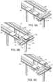
- one or more active conveyor segments 68 as in FIGS. 5 and 6 are used.
- Two closely spaced rails 70, 71 define a narrow slot 72 to receive and guide the blade 42 of the tray 36.
- the rails 70, 71 each have lateral extensions 74, 75 with flat tops 76, 77 supporting the tray 36.
- Primary conductor loops 78 powered by an ac power source extend along the length of the active conveyor section 68 in each rail extension 74, 75.
- the primary conductor loops 78 are mounted in E cores 80.
- the conductor loops are, for example, low-loss wire, such as Litz wire.
- Primary tuning capacitors are distributed across the loop along the length of the rails 70, 71 to provide highly efficient high-Q inductive power transfer to the secondary charging coils 62 in the tray 36.
- the majority of the conveyor can be constructed of active segments 68 as in FIG. 5 or of a combination of active segments and passive segments 22 as in FIG. 1 .
- a conveyor having a main carryway run along which articles are conveyed and a return run could have passive segments on the carryway and active inductive-power-transfer segments on the return to recharge the batteries.
- the active tray segment has a primary conductive loop on only one side. In that case a tray could be made with a secondary charging coil and tuning capacitor on only one side.
- FIG. 14 Yet another tray-charging or -powering arrangement is shown in FIG. 14 .
- the tray 180 has a single centrally located charging coil 62 connected in parallel with two tuning capacitors 64. Although two tuning capacitors 64 are shown, a single tuning capacitor could be used instead.
- a primary conductor loop is formed by a left conductor segment 182 in a left rail 184 connected to a right conductor segment 183 in a right rail 185.
- the endless primary conductor loop is tuned to resonance with one or more tuning capacitors (not shown) and is powered by an ac source (not shown).
- This version can be used with rails without lateral rail extensions.
- FIG. 7 One version of an electrical block diagram schematic of a conveyor as in FIG. 1 or FIG. 5 is shown in FIG. 7 .
- the tray controller 56 in this example is powered by either an external ac power source 82 or the battery 58. When the external source 82 is available, its power is inductively coupled to the tray from the primary conductive loop 78 to the secondary charging coil 62.
- the tuning capacitors 84, distributed along the length of the loop 78, and the tray tuning capacitor 64 tune the primary and secondary circuits to resonate at the frequency of the ac source 82 to maximize power transfer.
- the secondary ac voltage is converted to dc by a rectifier or ac-to-dc converter 86 whose output is diode-ORed with the battery voltage 92 through a diode 94 to produce a dc supply voltage 88 that powers the tray.
- a rectifier or ac-to-dc converter 86 whose output is diode-ORed with the battery voltage 92 through a diode 94 to produce a dc supply voltage 88 that powers the tray.
- the externally sourced voltage will exceed the battery voltage 92 and power the tray controller 56 and other active devices in the tray.
- the battery 58 switches in to power the tray when the externally sourced voltage drops below the battery voltage 92.
- the external voltage exceeds the battery voltage 92, it charges the battery 58 through a charging element 96.
- the diode-ORed arrangement constitutes a rudimentary switch that switches between external and battery power for the tray.
- One example of an alternative switch useful for switching from external power to battery power includes an electromechanical or an electronic switch that connects the tray's dc supply voltage 88 to the battery voltage 92 from the externally sourced dc voltage when the external power is too low.
- a low-voltage detector sensing the incoming ac voltage or its rectified dc voltage sends a low-voltage signal to the switch to switch to battery power.
- a series of magnetic field sensors 98 such as Hall-effect sensors positioned periodically along the length of the tray blade 42 ( FIG. 4 ), determine the position of the tray coils 54 relative to the magnetic-field positive and negative peaks.
- the sensor signals 99 are sent to the controller 56, which includes a commutator 100.
- the commutator 100 is a software routine that runs in program memory of the controller 56, e.g., a microcomputer or microcontroller.
- the commutator 100 generates three output signals 104, which are properly phased as determined by the sensor signals 99, to control the current through the three-phase forcer coils 54.
- the three output signals 104 are amplified by amplifiers 102 that supply the commutated current waveforms to the forcer coils 54 to drive the tray.
- the tray controller 56 in each tray communicates with a conveyor controller 106 external to the trays.
- a transmitter-receiver 108 on the tray circuit board 57 is linked wirelessly over antennas 110, 111 to an external transmitter-receiver 109 connected to the system controller 106.
- the system controller 106 sends command and data requests to the tray controllers 56 over the wireless link and receives data from the tray controllers.
- the tray antenna 110 is shown in FIG. 4 as a dipole embedded in the tray platform 38 along one end of the tray 36 as one example.
- a tray carriage 112 used to transfer trays from one conveyor segment to another is shown in FIG. 8 .
- the carriage 112 is the same as the trays described previously, but with a pair of passive transfer rails 114, 115 mounted on the top surface 116.
- the transfer rails 114, 115 have permanent-magnet arrays disposed along their lengths.
- the narrow slot 118 between the transfer rails 114, 115 extends in length perpendicular to the plane of the carriage blade 120.
- FIGS. 9A-9C illustrate how the carriage 112 transfers trays from one conveyor segment 68 to another 68'.
- a tray 36 advancing along a first conveyor segment 68 at an end of a first conveyor run is received on the transfer rails 114, 115 of the carriage 112.
- the carriage 112 is supported on a carriage conveyor segment 122 extending perpendicular to the planes of the slots 72 in the first and second conveyor segments 68, 68'.
- the carriage conveyor segment 122 is below the level of the tray conveyor segments 68, 68' so that the transfer rails 114, 115 are at the same level as the tray conveyor rails 70, 71.
- the transfer rails 114, 115 and the transfer slot 118 can be aligned with the tray coils 70, 71 and the tray slot 72 on the first tray conveyor segment 68 to smoothly receive the tray 36 as in FIG. 9A .
- the carriage 112 energizes its drive coils and propels itself and the tray 36 laterally in a transverse direction 116 as in FIG. 9B along the carriage conveyor segment 122.
- the carriage conveyor segment 122 has permanent-magnet carriage rails 124, 125 and a carriage slot 126 like the tray conveyor segments.
- the carriage segment 122 has a shorter leg 118 than the tray conveyor segment to position the top surface 128 of the carriage segment 122 skewed perpendicular to and below the tops of 76, 77 of the conveyor segments 68, 68'.
- the carriage 112 stops, and the tray 36 energizes itself to advance off the transfer rails 114, 115 and onto the aligned conveyor segment rails 70, 71 on the second conveyor segment 68'.
- an endless tray conveyor is formed. The carriage 112 then translates back to the first conveyor segment 68 to receive the next tray.
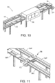
- a tray washer 130 is shown covering a portion of the return run 132 in an endless conveyor configuration 134 in FIG. 10 .
- a carriage conveyor segment 122 is shown at one end of the endless conveyor 134 for transferring trays 36 from a carryway run 133 to the return run 132.
- the tray washer 130 includes spray nozzles and brushes to clean, rinse, sanitize, and dry the trays 36.
- the carriage conveyor segment 122 can be used to transfer trays 36 between many conveyor sections 136A, 136B, 136C, 136D.
- the four tray conveyor sections are arranged parallel to each other with two on each side of a gap 138 across which the carriage 112 translates perpendicular to the tray conveyor sections 136A-D.
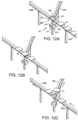
- the conveyor configuration of FIGS. 12A-12C has two tray conveyor segments 140A, 140B in line across a gap 142.
- a third tray conveyor segment 140C extends obliquely away from the gap 142.
- the obliquely oriented conveyor segment 140C constitutes a divert path for trays 36 away from a straight-through path on the in-line conveyor segment 140B.
- a diverter carriage segment 141 includes a diverter carriage 144 that resides in the gap 142.
- Diverter rails 146, 147 with embedded permanent-magnet arrays are selectively aligned with either the rails of the in-line tray conveyor segments 140A, 140B or with the oblique tray conveyor segment 140C.
- the diverter carriage 144 includes a post 148 extending downward from the rails 146, 147 to a diverter carriage platform 150, which is supported on a cylindrical diverter base 152.
- the base 152 houses a ring of permanent magnets that creates a magnetic field directed radially from the base's periphery.
- the diverter carriage platform 150 has side skirts 154 that extend downward around the periphery of the diverter base 152.
- Diverter carriage drive coils (not shown) in the skirts driven by a diverter controller (not shown) in the diverter carriage 144 produce an electromagnetic field that interacts with the permanent-magnet magnetic field of the base 152 to rotate the diverter carriage 144 between an in-line tray pass-through position as in FIGS.
- the diverter carriage segment 141 can be used to merge products from the tray segments 140B, 140C onto the tray segment 140A when the trays 36 advance opposite to the direction of the arrows in FIG. 12C .
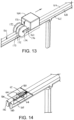
- a rail scrubber 160 is shown in FIG. 13 cleaning a tray conveyor section 162.
- the scrubber 160 has a housing 164 covering water, cleanser, and sanitizer tanks (not shown).
- the housing 164 mounts on a base (not shown) such as a conveyor tray with a drive-coil blade that fits in the slot 166 between the two rails 168, 169 and propels the scrubber 160 along the conveyor section 162.
- One or more nozzles 170 spray the water, cleanser, or sanitizer onto the rails 168, 169.
- Outer rotary brushes 172 and an inner rotary brush 173 are mounted on an axle 174 retained at its ends by arms 176 attached to the scrubber housing 164.
- the outer rotary brushes 172 have bristles at least on an inner side to scrub the outer sides of the rails 168, 169.
- the inner brush 173 rides in the slot 166 and has bristles on both side to scrub the inside walls of the rails 168, 169.
Landscapes
- Engineering & Computer Science (AREA)
- Power Engineering (AREA)
- Physics & Mathematics (AREA)
- Electromagnetism (AREA)
- Chemical & Material Sciences (AREA)
- Combustion & Propulsion (AREA)
- Transportation (AREA)
- Mechanical Engineering (AREA)
- Non-Mechanical Conveyors (AREA)
- Linear Motors (AREA)
Claims (10)
- Un convoyeur comprenant :un rail (26, 27) ayant un réseau d'aimants permanents (44) intégrés à et s'étendant le long du rail (26, 27) pour former un stator à aimants permanents créant un champ magnétique ;un plateau (36) supporté sur le rail (26, 27) et ayant une surface supérieure de support d'article (40) et ayant une série de bobines d'entraînement commutées (54) servant de forceur agissant conjointement avec le stator à aimants permanents pour former un moteur linéaire à courant continu sans balais pour propulser le plateau (36) le long du rail (26, 27) ;un segment convoyeur à plateau (22) s'étendant d'une première extrémité à une deuxième extrémité dans une direction de transport (46) et comprenant :une paire des rails (26, 27) faiblement espacés et séparés par une fente (34) et ayant des parties supérieures (28, 29), chacun des rails (26, 27) comprenant un tel réseau d'aimants permanents (44) créant un champ magnétique à travers la fente (34) ;dans lequel le plateau (36) comprend :une plate-forme (38) formant la surface supérieure de support d'article (40) et une surface inférieure (41) supportée sur les parties supérieures (28, 29) des rails (26, 27) ;une lame (42) s'étendant vers le bas depuis la surface inférieure (41) et dans la direction de transport (46) pour avancer dans la fente (34) et logeant la série de bobines d'entraînement commutées (54) ;un contrôleur de plateau (56) entraînant les bobines d'entraînement (54) pour produire une onde électromagnétique mobile qui agit conjointement avec le champ magnétique pour propulser le plateau (36) dans la direction de transport (46) ;la fente (34) s'élargissant au niveau des parties supérieures (28, 29) des rails (26, 27) et les parties supérieures (28, 29) des rails (26, 27) étant convexes.
- Un convoyeur conforme à la revendication 1, dans lequel :a) les bobines d'entraînement (54) sont des bobines triphasées, le contrôleur de plateau (56) commute le courant à travers les bobines triphasées (54) pour former le moteur linéaire à courant continu sans balais avec les réseaux d'aimants permanents dans les rails (26, 27) ; oub) les bobines d'entraînement (54) sont des bobines triphasées, le contrôleur de plateau (56) commute le courant à travers les bobines triphasées (54) pour former le moteur linéaire à courant continu sans balais avec les réseaux d'aimants permanents dans les rails (26, 27) et dans lequel le plateau (36) comprend des capteurs dans la lame (42) pour détecter l'amplitude du champ magnétique et envoyer des signaux de capteur au contrôleur du plateau (56) pour commuter le courant.
- Un convoyeur conforme à la revendication 1, dans lequel les bobines d'entraînement (54) ont des noyaux sans fer.
- Un convoyeur conforme à la revendication 1, comportant en sus une boucle conductrice primaire (78) à l'extérieur du plateau (36) et s'étendant dans la direction de transport (46) le long des rails (26, 27) et dans lequel le plateau (36) comporte en sus une bobine secondaire (62) couplée de manière inductive à la boucle conductrice primaire (78) pour alimenter le plateau (36) en puissance pendant qu'il est le long des rails (26, 27).
- Un convoyeur conforme à la revendication 4, dans lequel le plateau (36) comporte une batterie (58) pour alimenter en puissance le contrôleur du plateau (56) et la série de bobines d'entraînement (54), la batterie (58) étant rechargée par l'intermédiaire de la bobine secondaire (62).
- Un convoyeur conforme à la revendication 1, comportant en sus une base de rails (30) reliant les rails (26, 27) et formant une extrémité fermée de la fente (34) et une série de pieds simples (32) s'étendant vers le bas depuis la base (30) pour monter le convoyeur sur un sol.
- Un convoyeur conforme à la revendication 1, comportant en sus :un segment convoyeur à chariot (122) comme le segment convoyeur à plateau mais agencé avec des rails pour chariot (124, 125) et une fente pour chariot (126) perpendiculaire à et inclinée sous les rails et la fente du segment convoyeur à plateau ;un chariot (112) comprenant :une plate-forme pour chariot supportée sur les parties supérieures des rails pour chariot (124, 125) ;une lame pour chariot (120) s'étendant vers le bas depuis la plate-forme pour chariot pour avancer dans la fente pour chariot (126) ;une série de bobines d'entraînement pour chariot dans la lame pour chariot ;une paire de rails de transfert faiblement espacés (114, 115) séparés par une fente de transfert (118) et s'étendant vers le haut depuis la plate-forme pour chariot jusqu'aux parties supérieures au niveau des parties supérieures des rails dans le segment convoyeur à plateau recevant un plateau ou déchargeant un plateau dans le segment convoyeur à plateau ;un contrôleur de chariot entraînant les bobines d'entraînement du chariot pour produire une onde électromagnétique mobile qui agit conjointement avec le champ magnétique dans la fente pour chariot (126) pour propulser le chariot (112) le long du segment convoyeur à chariot (122) en direction transversale (116) depuis une première position dans laquelle les rails de transfert (114, 115) sont alignés avec les rails du segment convoyeur à plateau jusqu'à une deuxième position dans laquelle les rails de transfert sont décalés transversalement des rails du segment convoyeur à plateau.
- Un convoyeur conforme à la revendication 1, comportant en sus :une pluralité de segments convoyeurs à chariot (140A, 140B, 140C) dans laquelle un premier des segments convoyeurs à chariot (140C) s'étend en oblique depuis la première extrémité d'un deuxième des segments convoyeurs à chariot à travers un espace (142) ;un segment pour chariot dérivateur (141) ayant une base de dérivation cylindrique (152) logeant un anneau d'aimants permanents créant un champ magnétique autour de la périphérie de la base de dérivation ;un chariot dérivateur (144) comprenant :une plate-forme de chariot dérivateur (150) supportée sur la base de dérivation (152) et ayant des jupes latérales (154) s'étendant vers le bas autour de la périphérie de la base de dérivation (152) ;une série de bobines d'entraînement de chariot dérivateur dans chacune des jupes latérales (154) ;une paire de rails dérivateurs faiblement espacés (146, 147) séparés par une fente de dérivation et s'étendant vers le haut depuis la plate-forme de chariot dérivateur vers des parties supérieures au niveau des parties supérieures des rails dans les premier et deuxième segments convoyeurs à plateau (140A, 140B, 140C) pour recevoir un plateau ou décharger un plateau vers le segment convoyeur à plateau ;un contrôleur de chariot dérivateur entraînant les bobines d'entraînement de chariot dérivateur pour produire une onde électromagnétique mobile qui agit conjointement avec le champ magnétique de la base de dérivation (152) pour faire tourner le dérivateur d'une première position dans laquelle les rails de dérivation sont alignés avec les rails du premier des segments convoyeurs à plateau jusqu'à une deuxième position dans laquelle les rails de dérivation sont alignés avec les rails du deuxième des segments convoyeurs à plateau.
- Un convoyeur conforme à la revendication 1, comportant en sus un racleur (160) comprenant :une lame qui avance dans la fente (166) ;une série de bobines de racleur logées dans la lame ;un contrôleur de racleur entraînant les bobines de racleur pour produire une onde électromagnétique mobile qui agit conjointement avec le champ magnétique pour propulser le plateau le long du segment convoyeur à plateau ;une réserve de solution nettoyante ;une buse de pulvérisation (170) pulvérisant la solution nettoyante sur les rails.
- Un convoyeur conforme à la revendication 9, dans lequel le racleur comporte en sus des brosses racleuses rotatives (172, 173) qui avancent dans la fente (166) et le long des côtés extérieurs des rails.
Applications Claiming Priority (2)
| Application Number | Priority Date | Filing Date | Title |
|---|---|---|---|
| US201762500267P | 2017-05-02 | 2017-05-02 | |
| PCT/US2018/025779 WO2018204006A1 (fr) | 2017-05-02 | 2018-04-03 | Convoyeur à plateaux entraîné par un moteur à courant continu sans balai |
Publications (3)
| Publication Number | Publication Date |
|---|---|
| EP3619149A1 EP3619149A1 (fr) | 2020-03-11 |
| EP3619149A4 EP3619149A4 (fr) | 2021-01-13 |
| EP3619149B1 true EP3619149B1 (fr) | 2025-07-09 |
Family
ID=64016208
Family Applications (1)
| Application Number | Title | Priority Date | Filing Date |
|---|---|---|---|
| EP18794640.5A Active EP3619149B1 (fr) | 2017-05-02 | 2018-04-03 | Convoyeur à plateaux entraîné par un moteur à courant continu sans balai |
Country Status (6)
| Country | Link |
|---|---|
| US (1) | US10994953B2 (fr) |
| EP (1) | EP3619149B1 (fr) |
| JP (1) | JP7177785B2 (fr) |
| CN (1) | CN110612260B (fr) |
| ES (1) | ES3035815T3 (fr) |
| WO (1) | WO2018204006A1 (fr) |
Families Citing this family (6)
| Publication number | Priority date | Publication date | Assignee | Title |
|---|---|---|---|---|
| US10965201B2 (en) * | 2017-09-25 | 2021-03-30 | Canon Kabushiki Kaisha | Transport system, processing system and manufacturing method of article |
| DE202020102692U1 (de) * | 2020-05-13 | 2020-06-05 | Markus Pfuderer | Modulares Transfersystem |
| CN113277279A (zh) * | 2021-06-21 | 2021-08-20 | 大工科技(上海)有限公司 | 一种基于柔性智能传输平台的舞台场景综合控制系统 |
| BR102021018108A2 (pt) | 2021-09-13 | 2023-03-28 | Freed Participaçoes S/A | Esteira transportadora tracionada por motor de indução linear com primário de dupla face e secundário longo seccionado |
| CN116393879B (zh) * | 2023-06-02 | 2023-09-08 | 西安热工研究院有限公司 | 一种高处管道自动化焊接设备及方法 |
| CN222138077U (zh) * | 2024-09-24 | 2024-12-10 | 宁德时代新能源科技股份有限公司 | 电池传送装置和电池烘干系统 |
Citations (6)
| Publication number | Priority date | Publication date | Assignee | Title |
|---|---|---|---|---|
| EP0241875A2 (fr) * | 1986-04-11 | 1987-10-21 | Compact Spindle Bearing Corporation | Moteur linéaire à commutation par semi-conducteurs avec armature multiphasée sans fer |
| JP2004015894A (ja) * | 2002-06-05 | 2004-01-15 | Yaskawa Electric Corp | リニアモータ |
| EP1956705A1 (fr) * | 2005-11-30 | 2008-08-13 | THK Co., Ltd. | Actionneur sans fil |
| US20130187573A1 (en) * | 2010-09-30 | 2013-07-25 | Thk Co., Ltd. | Control apparatus for linear motor, and linear motor apparatus |
| WO2014059134A1 (fr) * | 2012-10-11 | 2014-04-17 | Siemens Healthcare Diagnostics Inc. | Porteur de maintenance d'automatisation |
| US8829740B2 (en) * | 2010-05-27 | 2014-09-09 | Rockwell Automation Technologies, Inc. | Sealed linear motor system |
Family Cites Families (24)
| Publication number | Priority date | Publication date | Assignee | Title |
|---|---|---|---|---|
| US3625181A (en) | 1969-10-27 | 1971-12-07 | Arthur J Weaver | Apparatus for cleaning and oiling paving forms |
| US3788447A (en) * | 1972-07-03 | 1974-01-29 | Fmc Corp | Linear motor conveyor |
| US3786779A (en) | 1972-09-13 | 1974-01-22 | Klenco Corp | Overhead rail cleaner and oiler |
| US4092554A (en) * | 1977-05-19 | 1978-05-30 | The Raymond Lee Organization, Inc. | Linear electric generating system |
| JPS60229603A (ja) | 1984-04-26 | 1985-11-15 | Toshiba Corp | 搬送装置 |
| NL8902586A (nl) * | 1989-10-19 | 1991-05-16 | Vanderlande Ind Nederland | Transportinrichting. |
| JPH0432478U (fr) * | 1990-07-16 | 1992-03-17 | ||
| GB9419734D0 (en) * | 1994-09-30 | 1994-11-16 | Linear Drives Ltd | Linear motor for extended travel |
| JP3446563B2 (ja) * | 1997-10-23 | 2003-09-16 | 日立金属株式会社 | リニアモータ |
| US6279728B1 (en) | 1998-07-20 | 2001-08-28 | Norbert G Jung | Electro-magnetic conveyor |
| TWI248718B (en) | 1999-09-02 | 2006-02-01 | Koninkl Philips Electronics Nv | Displacement device |
| JP3755366B2 (ja) * | 2000-01-19 | 2006-03-15 | 株式会社ダイフク | 荷搬送設備 |
| US6629503B2 (en) * | 2001-06-29 | 2003-10-07 | The Regents Of The University Of California | Inductrack configuration |
| US6684794B2 (en) | 2002-05-07 | 2004-02-03 | Magtube, Inc. | Magnetically levitated transportation system and method |
| KR20070099609A (ko) | 2005-01-17 | 2007-10-09 | 코닌클리케 필립스 일렉트로닉스 엔.브이. | 이동 디바이스 |
| WO2009083889A1 (fr) | 2007-12-28 | 2009-07-09 | Koninklijke Philips Electronics N.V. | Levage sans contact d'un objet par un moteur planaire inversé |
| JP5480597B2 (ja) | 2009-11-04 | 2014-04-23 | ヤマハ発動機株式会社 | リニア搬送装置 |
| DE102012220008B4 (de) * | 2012-11-02 | 2023-06-01 | Syntegon Technology Gmbh | Transportvorrichtung mit steuerbarem Förderelement |
| JP6067421B2 (ja) | 2013-03-01 | 2017-01-25 | 住友重機械工業株式会社 | リニアモータ |
| US9802507B2 (en) | 2013-09-21 | 2017-10-31 | Magnemotion, Inc. | Linear motor transport for packaging and other uses |
| JP5855631B2 (ja) * | 2013-12-17 | 2016-02-09 | ファナック株式会社 | リニアモータを備えた直線駆動装置を有する工作機械 |
| JP6313642B2 (ja) * | 2014-04-18 | 2018-04-18 | キヤノン株式会社 | リニアモータ制御装置及びリニアモータ制御システム |
| DE102014225171A1 (de) | 2014-12-08 | 2016-06-09 | Robert Bosch Gmbh | Sicherungssystem für eine Anordnung zum Bewegen von Transportkörpern |
| US9611107B2 (en) | 2014-12-08 | 2017-04-04 | Rockwell Automation Technologies, Inc. | Linear drive transport system and method |
-
2018
- 2018-04-03 JP JP2019555181A patent/JP7177785B2/ja active Active
- 2018-04-03 EP EP18794640.5A patent/EP3619149B1/fr active Active
- 2018-04-03 CN CN201880028303.0A patent/CN110612260B/zh active Active
- 2018-04-03 ES ES18794640T patent/ES3035815T3/es active Active
- 2018-04-03 US US16/609,694 patent/US10994953B2/en active Active
- 2018-04-03 WO PCT/US2018/025779 patent/WO2018204006A1/fr not_active Ceased
Patent Citations (6)
| Publication number | Priority date | Publication date | Assignee | Title |
|---|---|---|---|---|
| EP0241875A2 (fr) * | 1986-04-11 | 1987-10-21 | Compact Spindle Bearing Corporation | Moteur linéaire à commutation par semi-conducteurs avec armature multiphasée sans fer |
| JP2004015894A (ja) * | 2002-06-05 | 2004-01-15 | Yaskawa Electric Corp | リニアモータ |
| EP1956705A1 (fr) * | 2005-11-30 | 2008-08-13 | THK Co., Ltd. | Actionneur sans fil |
| US8829740B2 (en) * | 2010-05-27 | 2014-09-09 | Rockwell Automation Technologies, Inc. | Sealed linear motor system |
| US20130187573A1 (en) * | 2010-09-30 | 2013-07-25 | Thk Co., Ltd. | Control apparatus for linear motor, and linear motor apparatus |
| WO2014059134A1 (fr) * | 2012-10-11 | 2014-04-17 | Siemens Healthcare Diagnostics Inc. | Porteur de maintenance d'automatisation |
Also Published As
| Publication number | Publication date |
|---|---|
| US10994953B2 (en) | 2021-05-04 |
| JP2020519220A (ja) | 2020-06-25 |
| ES3035815T3 (en) | 2025-09-09 |
| WO2018204006A1 (fr) | 2018-11-08 |
| CN110612260A (zh) | 2019-12-24 |
| BR112019021151A2 (pt) | 2020-05-12 |
| EP3619149A1 (fr) | 2020-03-11 |
| JP7177785B2 (ja) | 2022-11-24 |
| EP3619149A4 (fr) | 2021-01-13 |
| US20200198905A1 (en) | 2020-06-25 |
| CN110612260B (zh) | 2021-12-24 |
Similar Documents
| Publication | Publication Date | Title |
|---|---|---|
| EP3619149B1 (fr) | Convoyeur à plateaux entraîné par un moteur à courant continu sans balai | |
| US11715977B2 (en) | Method and system for contactless power transfer in a linear drive system | |
| JP7432627B2 (ja) | リニアモータコンベヤシステム | |
| US11303242B2 (en) | Method and apparatus for wireless power transfer to an independent moving cart | |
| US20210234488A1 (en) | System and Method for Wireless Power Transfer in a Linear Cart System | |
| JP7443428B2 (ja) | モノレールトレイコンベア | |
| US20210384765A1 (en) | Method and Apparatus for Data Transmission over an Inductive Link for an Independent Cart System | |
| EP3461677A1 (fr) | Génération de tension par bus moyen par l'intermédiaire de phases de veille dans un système de suivi à moteur linéaire | |
| CN117595524A (zh) | 独立推车系统中的在线无线能量传输和感测的系统和方法 | |
| AU2018331269B2 (en) | Monorail tray conveyor with passive guide rails | |
| BR112019021151B1 (pt) | Transportador |
Legal Events
| Date | Code | Title | Description |
|---|---|---|---|
| STAA | Information on the status of an ep patent application or granted ep patent |
Free format text: STATUS: THE INTERNATIONAL PUBLICATION HAS BEEN MADE |
|
| PUAI | Public reference made under article 153(3) epc to a published international application that has entered the european phase |
Free format text: ORIGINAL CODE: 0009012 |
|
| STAA | Information on the status of an ep patent application or granted ep patent |
Free format text: STATUS: REQUEST FOR EXAMINATION WAS MADE |
|
| 17P | Request for examination filed |
Effective date: 20191017 |
|
| AK | Designated contracting states |
Kind code of ref document: A1 Designated state(s): AL AT BE BG CH CY CZ DE DK EE ES FI FR GB GR HR HU IE IS IT LI LT LU LV MC MK MT NL NO PL PT RO RS SE SI SK SM TR |
|
| AX | Request for extension of the european patent |
Extension state: BA ME |
|
| DAV | Request for validation of the european patent (deleted) | ||
| DAX | Request for extension of the european patent (deleted) | ||
| A4 | Supplementary search report drawn up and despatched |
Effective date: 20201210 |
|
| RIC1 | Information provided on ipc code assigned before grant |
Ipc: H02K 11/00 20160101ALI20201204BHEP Ipc: H02K 29/08 20060101ALI20201204BHEP Ipc: B65G 54/02 20060101AFI20201204BHEP Ipc: H02K 3/47 20060101ALI20201204BHEP Ipc: B60L 13/03 20060101ALI20201204BHEP Ipc: H02K 41/03 20060101ALI20201204BHEP Ipc: B65G 47/64 20060101ALN20201204BHEP |
|
| STAA | Information on the status of an ep patent application or granted ep patent |
Free format text: STATUS: EXAMINATION IS IN PROGRESS |
|
| 17Q | First examination report despatched |
Effective date: 20231114 |
|
| GRAP | Despatch of communication of intention to grant a patent |
Free format text: ORIGINAL CODE: EPIDOSNIGR1 |
|
| STAA | Information on the status of an ep patent application or granted ep patent |
Free format text: STATUS: GRANT OF PATENT IS INTENDED |
|
| RIC1 | Information provided on ipc code assigned before grant |
Ipc: B65G 47/64 20060101ALN20241231BHEP Ipc: B60L 13/03 20060101ALI20241231BHEP Ipc: H02K 11/00 20160101ALI20241231BHEP Ipc: H02K 29/08 20060101ALI20241231BHEP Ipc: H02K 3/47 20060101ALI20241231BHEP Ipc: H02K 41/03 20060101ALI20241231BHEP Ipc: B65G 54/02 20060101AFI20241231BHEP |
|
| INTG | Intention to grant announced |
Effective date: 20250130 |
|
| GRAS | Grant fee paid |
Free format text: ORIGINAL CODE: EPIDOSNIGR3 |
|
| GRAA | (expected) grant |
Free format text: ORIGINAL CODE: 0009210 |
|
| STAA | Information on the status of an ep patent application or granted ep patent |
Free format text: STATUS: THE PATENT HAS BEEN GRANTED |
|
| P01 | Opt-out of the competence of the unified patent court (upc) registered |
Free format text: CASE NUMBER: APP_20996/2025 Effective date: 20250502 |
|
| AK | Designated contracting states |
Kind code of ref document: B1 Designated state(s): AL AT BE BG CH CY CZ DE DK EE ES FI FR GB GR HR HU IE IS IT LI LT LU LV MC MK MT NL NO PL PT RO RS SE SI SK SM TR |
|
| REG | Reference to a national code |
Ref country code: GB Ref legal event code: FG4D |
|
| REG | Reference to a national code |
Ref country code: CH Ref legal event code: EP |
|
| REG | Reference to a national code |
Ref country code: NL Ref legal event code: FP Ref country code: IE Ref legal event code: FG4D |
|
| REG | Reference to a national code |
Ref country code: DE Ref legal event code: R096 Ref document number: 602018083437 Country of ref document: DE |
|
| REG | Reference to a national code |
Ref country code: ES Ref legal event code: FG2A Ref document number: 3035815 Country of ref document: ES Kind code of ref document: T3 Effective date: 20250909 |
|
| PG25 | Lapsed in a contracting state [announced via postgrant information from national office to epo] |
Ref country code: PT Free format text: LAPSE BECAUSE OF FAILURE TO SUBMIT A TRANSLATION OF THE DESCRIPTION OR TO PAY THE FEE WITHIN THE PRESCRIBED TIME-LIMIT Effective date: 20251110 |
|
| REG | Reference to a national code |
Ref country code: AT Ref legal event code: MK05 Ref document number: 1811699 Country of ref document: AT Kind code of ref document: T Effective date: 20250709 |
|
| PG25 | Lapsed in a contracting state [announced via postgrant information from national office to epo] |
Ref country code: IS Free format text: LAPSE BECAUSE OF FAILURE TO SUBMIT A TRANSLATION OF THE DESCRIPTION OR TO PAY THE FEE WITHIN THE PRESCRIBED TIME-LIMIT Effective date: 20251109 |
|
| PG25 | Lapsed in a contracting state [announced via postgrant information from national office to epo] |
Ref country code: NO Free format text: LAPSE BECAUSE OF FAILURE TO SUBMIT A TRANSLATION OF THE DESCRIPTION OR TO PAY THE FEE WITHIN THE PRESCRIBED TIME-LIMIT Effective date: 20251009 |
|
| REG | Reference to a national code |
Ref country code: LT Ref legal event code: MG9D |
|
| PG25 | Lapsed in a contracting state [announced via postgrant information from national office to epo] |
Ref country code: AT Free format text: LAPSE BECAUSE OF FAILURE TO SUBMIT A TRANSLATION OF THE DESCRIPTION OR TO PAY THE FEE WITHIN THE PRESCRIBED TIME-LIMIT Effective date: 20250709 |
|
| PG25 | Lapsed in a contracting state [announced via postgrant information from national office to epo] |
Ref country code: FI Free format text: LAPSE BECAUSE OF FAILURE TO SUBMIT A TRANSLATION OF THE DESCRIPTION OR TO PAY THE FEE WITHIN THE PRESCRIBED TIME-LIMIT Effective date: 20250709 |
|
| PG25 | Lapsed in a contracting state [announced via postgrant information from national office to epo] |
Ref country code: HR Free format text: LAPSE BECAUSE OF FAILURE TO SUBMIT A TRANSLATION OF THE DESCRIPTION OR TO PAY THE FEE WITHIN THE PRESCRIBED TIME-LIMIT Effective date: 20250709 |
|
| PG25 | Lapsed in a contracting state [announced via postgrant information from national office to epo] |
Ref country code: GR Free format text: LAPSE BECAUSE OF FAILURE TO SUBMIT A TRANSLATION OF THE DESCRIPTION OR TO PAY THE FEE WITHIN THE PRESCRIBED TIME-LIMIT Effective date: 20251010 |
|
| PG25 | Lapsed in a contracting state [announced via postgrant information from national office to epo] |
Ref country code: SE Free format text: LAPSE BECAUSE OF FAILURE TO SUBMIT A TRANSLATION OF THE DESCRIPTION OR TO PAY THE FEE WITHIN THE PRESCRIBED TIME-LIMIT Effective date: 20250709 |
|
| PG25 | Lapsed in a contracting state [announced via postgrant information from national office to epo] |
Ref country code: LV Free format text: LAPSE BECAUSE OF FAILURE TO SUBMIT A TRANSLATION OF THE DESCRIPTION OR TO PAY THE FEE WITHIN THE PRESCRIBED TIME-LIMIT Effective date: 20250709 |
|
| PG25 | Lapsed in a contracting state [announced via postgrant information from national office to epo] |
Ref country code: BG Free format text: LAPSE BECAUSE OF FAILURE TO SUBMIT A TRANSLATION OF THE DESCRIPTION OR TO PAY THE FEE WITHIN THE PRESCRIBED TIME-LIMIT Effective date: 20250709 Ref country code: PL Free format text: LAPSE BECAUSE OF FAILURE TO SUBMIT A TRANSLATION OF THE DESCRIPTION OR TO PAY THE FEE WITHIN THE PRESCRIBED TIME-LIMIT Effective date: 20250709 |
|
| PG25 | Lapsed in a contracting state [announced via postgrant information from national office to epo] |
Ref country code: RS Free format text: LAPSE BECAUSE OF FAILURE TO SUBMIT A TRANSLATION OF THE DESCRIPTION OR TO PAY THE FEE WITHIN THE PRESCRIBED TIME-LIMIT Effective date: 20251009 |
|
| PG25 | Lapsed in a contracting state [announced via postgrant information from national office to epo] |
Ref country code: SM Free format text: LAPSE BECAUSE OF FAILURE TO SUBMIT A TRANSLATION OF THE DESCRIPTION OR TO PAY THE FEE WITHIN THE PRESCRIBED TIME-LIMIT Effective date: 20250709 |
|
| PGFP | Annual fee paid to national office [announced via postgrant information from national office to epo] |
Ref country code: GB Payment date: 20260320 Year of fee payment: 9 |
|
| PG25 | Lapsed in a contracting state [announced via postgrant information from national office to epo] |
Ref country code: DK Free format text: LAPSE BECAUSE OF FAILURE TO SUBMIT A TRANSLATION OF THE DESCRIPTION OR TO PAY THE FEE WITHIN THE PRESCRIBED TIME-LIMIT Effective date: 20250709 |
|
| PGFP | Annual fee paid to national office [announced via postgrant information from national office to epo] |
Ref country code: NL Payment date: 20260323 Year of fee payment: 9 |
|
| PGFP | Annual fee paid to national office [announced via postgrant information from national office to epo] |
Ref country code: FR Payment date: 20260317 Year of fee payment: 9 |