EP3619480B1 - Verfahren zur steuerung des saugdrucks auf der basis einer am meisten belasteten kühleinheit - Google Patents
Verfahren zur steuerung des saugdrucks auf der basis einer am meisten belasteten kühleinheit Download PDFInfo
- Publication number
- EP3619480B1 EP3619480B1 EP18725759.7A EP18725759A EP3619480B1 EP 3619480 B1 EP3619480 B1 EP 3619480B1 EP 18725759 A EP18725759 A EP 18725759A EP 3619480 B1 EP3619480 B1 EP 3619480B1
- Authority
- EP
- European Patent Office
- Prior art keywords
- suction pressure
- cooling
- cooling entity
- pressure
- entity
- Prior art date
- Legal status (The legal status is an assumption and is not a legal conclusion. Google has not performed a legal analysis and makes no representation as to the accuracy of the status listed.)
- Active
Links
Images


Classifications
-
- F—MECHANICAL ENGINEERING; LIGHTING; HEATING; WEAPONS; BLASTING
- F25—REFRIGERATION OR COOLING; COMBINED HEATING AND REFRIGERATION SYSTEMS; HEAT PUMP SYSTEMS; MANUFACTURE OR STORAGE OF ICE; LIQUEFACTION SOLIDIFICATION OF GASES
- F25B—REFRIGERATION MACHINES, PLANTS OR SYSTEMS; COMBINED HEATING AND REFRIGERATION SYSTEMS; HEAT PUMP SYSTEMS
- F25B49/00—Arrangement or mounting of control or safety devices
- F25B49/02—Arrangement or mounting of control or safety devices for compression type machines, plants or systems
- F25B49/022—Compressor control arrangements
-
- F—MECHANICAL ENGINEERING; LIGHTING; HEATING; WEAPONS; BLASTING
- F25—REFRIGERATION OR COOLING; COMBINED HEATING AND REFRIGERATION SYSTEMS; HEAT PUMP SYSTEMS; MANUFACTURE OR STORAGE OF ICE; LIQUEFACTION SOLIDIFICATION OF GASES
- F25B—REFRIGERATION MACHINES, PLANTS OR SYSTEMS; COMBINED HEATING AND REFRIGERATION SYSTEMS; HEAT PUMP SYSTEMS
- F25B5/00—Compression machines, plants or systems, with several evaporator circuits, e.g. for varying refrigerating capacity
- F25B5/02—Compression machines, plants or systems, with several evaporator circuits, e.g. for varying refrigerating capacity arranged in parallel
-
- F—MECHANICAL ENGINEERING; LIGHTING; HEATING; WEAPONS; BLASTING
- F25—REFRIGERATION OR COOLING; COMBINED HEATING AND REFRIGERATION SYSTEMS; HEAT PUMP SYSTEMS; MANUFACTURE OR STORAGE OF ICE; LIQUEFACTION SOLIDIFICATION OF GASES
- F25B—REFRIGERATION MACHINES, PLANTS OR SYSTEMS; COMBINED HEATING AND REFRIGERATION SYSTEMS; HEAT PUMP SYSTEMS
- F25B49/00—Arrangement or mounting of control or safety devices
- F25B49/02—Arrangement or mounting of control or safety devices for compression type machines, plants or systems
-
- F—MECHANICAL ENGINEERING; LIGHTING; HEATING; WEAPONS; BLASTING
- F25—REFRIGERATION OR COOLING; COMBINED HEATING AND REFRIGERATION SYSTEMS; HEAT PUMP SYSTEMS; MANUFACTURE OR STORAGE OF ICE; LIQUEFACTION SOLIDIFICATION OF GASES
- F25B—REFRIGERATION MACHINES, PLANTS OR SYSTEMS; COMBINED HEATING AND REFRIGERATION SYSTEMS; HEAT PUMP SYSTEMS
- F25B2400/00—Component parts or details not otherwise provided for in this subclass
- F25B2400/07—Details of compressors or related parts
- F25B2400/075—Details of compressors or related parts with parallel compressors
-
- F—MECHANICAL ENGINEERING; LIGHTING; HEATING; WEAPONS; BLASTING
- F25—REFRIGERATION OR COOLING; COMBINED HEATING AND REFRIGERATION SYSTEMS; HEAT PUMP SYSTEMS; MANUFACTURE OR STORAGE OF ICE; LIQUEFACTION SOLIDIFICATION OF GASES
- F25B—REFRIGERATION MACHINES, PLANTS OR SYSTEMS; COMBINED HEATING AND REFRIGERATION SYSTEMS; HEAT PUMP SYSTEMS
- F25B2600/00—Control issues
- F25B2600/02—Compressor control
- F25B2600/025—Compressor control by controlling speed
-
- F—MECHANICAL ENGINEERING; LIGHTING; HEATING; WEAPONS; BLASTING
- F25—REFRIGERATION OR COOLING; COMBINED HEATING AND REFRIGERATION SYSTEMS; HEAT PUMP SYSTEMS; MANUFACTURE OR STORAGE OF ICE; LIQUEFACTION SOLIDIFICATION OF GASES
- F25B—REFRIGERATION MACHINES, PLANTS OR SYSTEMS; COMBINED HEATING AND REFRIGERATION SYSTEMS; HEAT PUMP SYSTEMS
- F25B2600/00—Control issues
- F25B2600/02—Compressor control
- F25B2600/027—Compressor control by controlling pressure
- F25B2600/0272—Compressor control by controlling pressure the suction pressure
-
- F—MECHANICAL ENGINEERING; LIGHTING; HEATING; WEAPONS; BLASTING
- F25—REFRIGERATION OR COOLING; COMBINED HEATING AND REFRIGERATION SYSTEMS; HEAT PUMP SYSTEMS; MANUFACTURE OR STORAGE OF ICE; LIQUEFACTION SOLIDIFICATION OF GASES
- F25B—REFRIGERATION MACHINES, PLANTS OR SYSTEMS; COMBINED HEATING AND REFRIGERATION SYSTEMS; HEAT PUMP SYSTEMS
- F25B2700/00—Sensing or detecting of parameters; Sensors therefor
- F25B2700/19—Pressures
- F25B2700/193—Pressures of the compressor
- F25B2700/1933—Suction pressures
-
- F—MECHANICAL ENGINEERING; LIGHTING; HEATING; WEAPONS; BLASTING
- F25—REFRIGERATION OR COOLING; COMBINED HEATING AND REFRIGERATION SYSTEMS; HEAT PUMP SYSTEMS; MANUFACTURE OR STORAGE OF ICE; LIQUEFACTION SOLIDIFICATION OF GASES
- F25B—REFRIGERATION MACHINES, PLANTS OR SYSTEMS; COMBINED HEATING AND REFRIGERATION SYSTEMS; HEAT PUMP SYSTEMS
- F25B2700/00—Sensing or detecting of parameters; Sensors therefor
- F25B2700/21—Temperatures
- F25B2700/2104—Temperatures of an indoor room or compartment
-
- F—MECHANICAL ENGINEERING; LIGHTING; HEATING; WEAPONS; BLASTING
- F25—REFRIGERATION OR COOLING; COMBINED HEATING AND REFRIGERATION SYSTEMS; HEAT PUMP SYSTEMS; MANUFACTURE OR STORAGE OF ICE; LIQUEFACTION SOLIDIFICATION OF GASES
- F25B—REFRIGERATION MACHINES, PLANTS OR SYSTEMS; COMBINED HEATING AND REFRIGERATION SYSTEMS; HEAT PUMP SYSTEMS
- F25B2700/00—Sensing or detecting of parameters; Sensors therefor
- F25B2700/21—Temperatures
- F25B2700/2117—Temperatures of an evaporator
Definitions
- the present invention relates to a method for controlling suction pressure in a vapour compression system.
- the suction pressure is controlled in such a manner that the cooling need of each cooling entity can be met, while keeping the energy consumption of the vapour compression system as low as possible.
- a vapour compression system such as a refrigeration system, an air condition system or a heat pump
- a fluid medium such as a refrigerant
- Refrigerant leaving the evaporator(s) enters a suction line which interconnects the outlet(s) of the evaporator(s) and the inlet of a compressor unit.
- the pressure prevailing in the suction line at the inlet of the compressor unit is referred to as the suction pressure.
- the suction pressure Since the suction line is connected to the outlet(s) of the evaporator(s), the suction pressure has an impact on the pressure prevailing in the evaporator(s), in the sense that changes in the suction pressure will result in corresponding changes in the pressure prevailing in the evaporator(s).
- the heat transfer taking place in an evaporator is dependent on the temperature difference between the evaporating temperature of the refrigerant passing through the evaporator and a target temperature of a refrigerated volume being cooled by means of the evaporator.
- the evaporating temperature is determined by the properties of the refrigerant and by the pressure prevailing in the evaporator, also referred to as the evaporating pressure.
- the pressure prevailing in the evaporator is determined by the suction pressure, and thereby the heat transfer taking place in the evaporator is affected by changes in the suction pressure.
- a low suction pressure results in a low evaporating pressure and a low evaporating temperature.
- a low evaporating temperature results in a large temperature difference between the evaporating temperature and the target temperature, and thereby a good heat transfer between the refrigerant and the air in the refrigerated volume. Therefore, in order to ensure good heat transfer, a low suction pressure should be selected.
- US 7,207,184 B2 discloses a method for regulating a most loaded circuit of a refrigeration system.
- Each circuit includes at least one case and an EEPR valve.
- the operation of each circuit is monitored and a load signal is calculated for each circuit.
- the load signals are compared and the most loaded circuit is determined.
- the EEPR valve of the most loaded circuit is adjusted to be approximately 100 percent open and a suction pressure of the compressor is adjusted to move a circuit temperature of the most loaded circuit to a target temperature.
- US-A-5 867 995 discloses a method for controlling suction pressure in a vapour compression system, the vapour compression system comprising one or more evaporators and a compressor that provides a suction pressure at the evaporator outlets.
- the invention provides a method for controlling suction pressure in a vapour compression system, according to claim 1.
- the method according to the invention is for controlling suction pressure in a vapour compression system.
- the term 'vapour compression system' should be interpreted to mean any system in which a flow of fluid medium, such as refrigerant, circulates and is alternatingly compressed and expanded, thereby providing either refrigeration or heating of a volume.
- the vapour compression system may be a refrigeration system, an air condition system, etc.
- the vapour compression system comprises a compressor unit, comprising one or more compressors, a heat rejecting heat exchanger and two or more cooling entities arranged in a refrigerant path.
- Each cooling entity comprises an expansion device and an evaporator arranged in thermal contact with a refrigerated volume.
- the refrigerated volume(s) could, e.g., be in the form of display case(s) in a supermarket.
- Refrigerant flowing in the refrigerant path is compressed by the compressor(s) of the compressor unit before being supplied to the heat rejecting heat exchanger.
- heat exchange takes place between the refrigerant and the ambient or a secondary fluid flow across the heat rejecting heat exchanger, in such a manner that heat is rejected from the refrigerant.
- the heat rejecting heat exchanger may be in the form of a condenser, in which the refrigerant is at least partly condensed.
- the heat rejecting heat exchanger may be in the form of a gas cooler, in which the refrigerant is cooled, but remains in a gaseous state.
- the refrigerant is passed to the expansion device(s), where the refrigerant is expanded before entering the evaporator(s).
- the expansion device(s) In the evaporator(s), heat exchange takes place between the refrigerant and the air in the refrigerated volumes, in such a manner that heat is absorbed by the refrigerant.
- the refrigerant passing through the evaporator(s) is at least partly evaporated.
- the refrigerant is supplied to the compressor unit, via a suction line.
- the suction pressure is the pressure prevailing in the suction line, at the inlet of the compressor unit.
- refrigerant circulating in the refrigerant path is alternatingly compressed by the compressor unit and expanded by the expansion device(s), while heat exchange takes place in the heat rejecting heat exchanger and the evaporator(s), respectively.
- a required change in suction pressure for maintaining a target temperature in the refrigerated volume is obtained, for each of the cooling entities.
- a change in suction pressure level which still ensures a heat transfer in the evaporator which is sufficient to maintain the target temperature in the refrigerated volume, is determined.
- the absolute suction pressure level need not be determined, only a relative change in the suction pressure level.
- the required change in suction pressure for a given cooling entity reflects the current load of that cooling entity, in the sense that it reflects a suction pressure level which is required in order for that cooling entity to be able to maintain the target temperature in the refrigerated volume.
- the required suction pressure may be substantially equal to a required evaporating pressure for a given cooling entity.
- a pressure drop will normally be introduced in the suction line between the outlet of the evaporator and the inlet of the compressor unit, and therefore the required suction level will normally be lower than the required evaporating pressure.
- the pressure drop depends on the length of the suction line as well as on other properties of the suction line, and it may depend on the pressure level.
- the maximum required suction level could, e.g., be derived from a maximum required evaporating pressure, taking the pressure drop into account. This will be described in further detail below.
- a most loaded cooling entity among the one or more cooling entities is identified, based on the required changes in suction pressure.
- the term 'most loaded cooling entity' should be interpreted to mean the cooling entity which is currently requiring the lowest suction pressure.
- suction pressure of the vapour compression system is controlled in accordance with the maximum required suction pressure and/or required change in suction pressure for the identified most loaded cooling entity.
- Changes in suction pressure are obtained for each of the cooling entities, and the suction pressure is controlled in such a manner that it is adjusted by an amount which is determined by the change in suction pressure for the identified most loaded cooling entity. This will typically be the change which results in the highest decrease of the suction pressure or, in the case that all the obtained changes in suction pressure specify an increase in suction pressure, the change which results in the lowest increase in suction pressure.
- the vapour compression system comprises two or more cooling entities. In this case one of these cooling entities is identified as the most loaded cooling entity.
- the step of controlling the suction pressure may comprise the steps of:
- an absolute setpoint value for the suction pressure is not provided to the controller, based on the identification of the most loaded cooling entity. Instead, the most loaded cooling entity is allowed to 'dictate' how much the current suction pressure is to be adjusted, including whether the suction pressure should be increased or decreased.
- the step of controlling the compressor capacity could, e.g., include adjusting a setpoint value for the suction pressure in accordance with the suction pressure adjustment, ⁇ P, and subsequently controlling the compressor capacity in accordance with the adjusted setpoint value, e.g. in the manner described above.
- the step of obtaining a required change in suction pressure for a given cooling entity may be performed by a cooling entity controller arranged to control a supply of refrigerant to that cooling entity.
- a cooling entity controller arranged to control a supply of refrigerant to that cooling entity.
- 'local' entity controllers associated with the individual cooling entities derive the maximum required suction pressures and/or required changes in suction pressure, and provides this information to a 'central' controller which is arranged to control the suction pressure.
- the 'central' controller may then apply the information received from each of the entity controllers in order to identify the most loaded cooling entity and control the suction pressure accordingly.
- the step of obtaining a required change in suction pressure for each of the cooling entities may be performed by a central controller, e.g. in the form of a frontend controller or the like.
- the method may further comprise the step of deriving performance information relating to the cooling entities and/or relating to the vapour compression system based on the obtained maximum required suction pressures.
- the method may further comprise the step of, for each cooling entity, obtaining a maximum required evaporating pressure for maintaining a target temperature in the refrigerated volume, and the step of obtaining a maximum required suction pressure and/or change in suction pressure for a given cooling entity may be based on the maximum required evaporating pressure for that cooling entity.
- a maximum required evaporating pressure for maintaining a target temperature in the refrigerated volume is initially obtained.
- a certain minimum temperature difference between the target temperature and the evaporating temperature of the refrigerant there must be a certain minimum temperature difference between the target temperature and the evaporating temperature of the refrigerant.
- the evaporating temperature is dependent on the evaporating pressure, and therefore a certain evaporating pressure, corresponding to the evaporating temperature providing the required minimum temperature difference, must prevail in the evaporator.
- This evaporating pressure can be obtained by providing a suitably corresponding suction pressure, since the outlet of the evaporator is directly connected to the suction line, and the pressure prevailing in the evaporator is therefore dependent on the suction pressure.
- the suction pressure required in order to provide a given evaporating pressure may be substantially equal to the evaporating pressure. However, a pressure drop will normally be introduced in the suction line, and therefore the required suction pressure is normally somewhat lower than the required evaporating pressure.
- the required suction pressure may be derived or calculated from the required evaporating pressure in various ways. For instance, a model based approach may be applied, in which knowledge about the design of the suction line and properties of the refrigerant may be used for generating a model for the correlation between the suction pressure and the evaporating pressure, and this model may subsequently be used for deriving the required suction pressure. Alternatively or additionally, a constant pressure drop in the suction line may be assumed, in which case the required suction pressure is simply assumed to be a pressure level which is lower than the required evaporating pressure by a pressure difference which is equal to the constant pressure drop. As another alternative, an empirical approach may be applied, in which corresponding values of evaporating pressure and suction pressure are measured and possibly stored in a look-up table, which is subsequently used for deriving the required suction pressure from the required evaporating pressure.
- the step of identifying a most loaded cooling entity may further be based on the maximum required evaporating pressures. For instance, the maximum required evaporating pressures may be compared, and the cooling entity having the lowest maximum required evaporating pressure may be identified as the most loaded cooling entity.
- Fig. 1 is a diagrammatic view of a vapour compression system 1 being controlled by means of a method according to an embodiment of the invention.
- the vapour compression system 1 comprises a compressor unit 2 comprising a number of compressors 3, three of which are shown, a heat rejecting heat exchanger 4 and two cooling entities 5 arranged in a refrigerant path. It should be noted that it is not ruled out that the vapour compression system 1 comprises further cooling entities 5.
- Each cooling entity 5 comprises an expansion device 6, in the form of an expansion valve, and an evaporator 7.
- the evaporators 7 are each arranged in thermal contact with a refrigerated volume, e.g. in the form of a display case.
- the expansion devices 6 each control the supply of refrigerant to the corresponding evaporator 7.
- the pressure of refrigerant entering the compressor unit 2 is referred to as the suction pressure. This pressure level is controlled in accordance with a method according to an embodiment of the invention.
- the target temperature is typically an air temperature inside the refrigerated volume which is required in order to maintain the quality of products stored in the refrigerated volume.
- Obtaining the required change in suction pressure for a given cooling entity 5 could, e.g., include determining the highest possible evaporating temperature which would ensure a sufficient heat transfer between the refrigerant flowing through the evaporator 7 and the air inside the refrigerated volume to maintain the target temperature inside the refrigerated volume.
- a required change in evaporating temperature could be determined.
- a corresponding evaporating pressure, or change in evaporating pressure can be derived, based on characteristics of the refrigerant. Based on this derived evaporating pressure, or change in evaporating pressure, a corresponding change in suction pressure, can be derived, with due consideration to any pressure drop which might take place between the evaporator 7 and the inlet of the compressor unit 2.
- the most loaded cooling entity 5 is identified, based on the required changes in suction pressure. This could, e.g., include comparing the obtained required changes in suction pressure and selecting the cooling entity 5 which requires the lowest suction pressure in order to be able to maintain the required target temperature in its refrigerated volume.
- the lower the suction pressure the lower the pressure levels in the evaporators 7 will be.
- a low pressure level in an evaporator 7 provides a low evaporating temperature, and thereby a large temperature difference between the evaporating temperature and the target temperature inside the refrigerated volume. This, in turn, provides a good heat transfer between the refrigerant flowing through the evaporator 7 and the air inside the refrigerated volume.
- the suction pressure the easier it will be for the cooling entities 5 to maintain the target temperatures inside the refrigerated volumes. It can therefore be assumed that if the suction pressure is controlled to be at a level which corresponds to the highest possible suction pressure which enables the most loaded cooling entity 5 to maintain the target temperature in its refrigerated volume, then the suction pressure will also be sufficiently low to enable all of the other cooling entities 5 to maintain the target temperature in their respective refrigerated volumes.
- the suction pressure is subsequently controlled in accordance with the maximum required suction pressure and/or required change in suction pressure for the identified most loaded cooling entity 5.
- Fig. 2 is a control diagram illustrating a method according to an embodiment of the invention.
- a requested change in suction temperature, ⁇ T e,req,i is obtained for each cooling entity of the vapour compression system.
- 'i' is the numbering of the cooling entities, and N is the number of cooling entities in the suction group.
- the requested change in suction temperature of the most loaded cooling entity is supplied to an adder 8 which also receives a user defined suction temperature setpoint value, T suc,SP .
- adder 8 the requested change in suction temperature of the most loaded cooling entity, ⁇ T e,req,MLC , and the user defined suction temperature setpoint value, T suc,SP , are added.
- the output from adder 8 is a suction temperature reference, T suc,ref , which is supplied to a second adder 10.
- the current suction temperature, T suc,current is subtracted from the suction temperature reference, T suc,ref .
- the output of the second adder 10 is supplied to a suction pressure controller 12 which controls the suction pressure of the vapour compression system in accordance therewith, e.g. applying a proportional integral (PI) control strategy.
- PI proportional integral
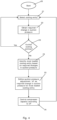
- Fig. 3 is a flow chart illustrating a method for controlling suction pressure of a vapour compression system according to a first embodiment of the invention.
- the vapour compression system could, e.g., be of the kind illustrated in Fig. 1 .
- the process is started at step 13.
- one of the cooling entities of the vapour compression system is selected.
- a maximum required suction pressure for maintaining a target temperature in the refrigerated volume of the selected cooling entity is obtained.
- the maximum required suction pressure is the highest suction pressure which results in a heat transfer between refrigerant flowing through the evaporator and the air inside the refrigerated volume being sufficient to maintain the target temperature inside the refrigerated volume.
- step 16 it is investigated whether or not further cooling entities exist, i.e. whether or not a maximum required suction pressure has been obtained for all of the cooling entities of the vapour compression system. If further cooling entities exist, the process is returned to step 14, and a new cooling entity is selected.
- step 16 reveals that there are no further cooling entities, i.e. that a maximum required suction pressure has been obtained for all of the cooling entities of the vapour compression system
- the process is forwarded to step 17.
- the cooling entity with the lowest maximum required suction pressure is identified. This could, e.g., include comparing the maximum required suction pressures obtained for each of the cooling entities.
- the identified cooling entity is regarded as the most loaded cooling entity.
- a suction pressure setpoint, P 0 is defined as the maximum required suction pressure of the most loaded cooling entity, which was identified in step 17. Since the most loaded cooling entity is the one which requires the lowest suction pressure in order to be able to maintain the target temperature inside its refrigerated volume, controlling the suction pressure to this level will ensure that the suction pressure is sufficiently low to ensure that all of the cooling entities are able to maintain the target temperature inside their respective refrigerated volumes.
- step 19 the compressor capacity of the vapour compression system is controlled according to this suction pressure setpoint, P 0 .
- Fig. 4 is a flow chart illustrating a method for controlling suction pressure of a vapour compression system according to a second embodiment of the invention.
- the vapour compression system could, e.g., be of the kind illustrated in Fig. 1 .
- the process is started at step 20.
- one of the cooling entities of the vapour compression system is selected.
- a required change in suction pressure for maintaining a target temperature in the refrigerated volume of the selected cooling entity is obtained.
- the required change in suction pressure is the minimum change with respect to the current suction pressure, which is required in order to ensure a heat transfer between refrigerant flowing through the evaporator and the air inside the refrigerated volume being sufficient to maintain the target temperature inside the refrigerated volume.
- step 23 it is investigated whether or not further cooling entities exist, i.e. whether or not a required change in suction pressure has been obtained for all of the cooling entities of the vapour compression system. If further cooling entities exist, the process is returned to step 21, and a new cooling entity is selected.
- step 23 reveals that there are no further cooling entities, i.e. that a required change in suction pressure has been obtained for all of the cooling entities of the vapour compression system
- the process is forwarded to step 24.
- the most loaded cooling entity is identified, based on the required changes in suction pressure. More specifically, the most loaded cooling entity is the one where the required change in suction pressure results in the lowest suction pressure.
- a suction pressure adjustment, ⁇ P is defined as the required change in suction pressure for the most loaded cooling entity, which was identified in step 24. Since the most loaded cooling entity is the one which requires the lowest suction pressure in order to be able to maintain the target temperature inside its refrigerated volume, adjusting the suction pressure by this required change in suction pressure will ensure that the suction pressure is sufficiently low to ensure that all of the cooling entities are able to maintain the target temperature inside their respective refrigerated volumes.
- step 26 the compressor capacity of the vapour compression system is controlled according to this suction pressure adjustment, ⁇ P.
- This could, e.g., include adjusting a suction pressure setpoint value by the suction pressure adjustment, ⁇ P, and subsequently control the compressor capacity in accordance with the adjusted setpoint value.
Landscapes
- Engineering & Computer Science (AREA)
- Physics & Mathematics (AREA)
- Mechanical Engineering (AREA)
- Thermal Sciences (AREA)
- General Engineering & Computer Science (AREA)
- Devices That Are Associated With Refrigeration Equipment (AREA)
- Cold Air Circulating Systems And Constructional Details In Refrigerators (AREA)
Claims (7)
- Verfahren zum Steuern eines Saugdrucks in einem Dampfkompressionssystem (1), wobei das Dampfkompressionssystem (1) eine Kompressoreinheit (2), einen wärmeabgebenden Wärmetauscher (4) und zwei oder mehrere Kühlelemente (5) umfasst, die in einem Kältemittelpfad angeordnet sind, wobei jedes Kühlelement (5) eine Expansionsvorrichtung (6) und einen Verdampfer (7) umfasst, die in thermischem Kontakt mit einem gekühlten Volumen angeordnet sind,
dadurch gekennzeichnet, dass das Verfahren die folgenden Schritte umfasst:- für jedes Kühlelement (5), Erhalten einer erforderlichen Änderung eines Saugdrucks zum Aufrechterhalten einer Zieltemperatur in dem gekühlten Volumen,- Ermitteln eines Kühlelements (5) mit der größten Last unter den zwei oder mehreren Kühlelementen (5) basierend auf den erforderlichen Änderungen des Saugdrucks, wobei das Kühlelement (5) mit der größten Last das Kühlelement (5) ist, für das die erforderliche Änderung des Saugdrucks zum Aufrechterhalten der Zieltemperatur in dem gekühlten Volumen zum niedrigsten Saugdruck führt, und- Steuern des Saugdrucks des Dampfkompressionssystems (1) gemäß der erforderlichen Änderung des Saugdrucks für das ermittelte Kühlelement (5) mit der größten Last. - Verfahren nach Anspruch 1, wobei der Schritt zum Steuern des Saugdrucks die folgenden Schritte umfasst:- Definieren einer Saugdruckanpassung, ΔP, für den Saugdruck, wobei die Saugdruckanpassung, ΔP, die erforderliche Änderung des Saugdrucks für das Kühlelement (5) mit der größten Last ist, und- Steuern einer Kompressorkapazität der Kompressoreinheit (2) gemäß der definierten Saugdruckanpassung, ΔP, und um eine Anpassung des aktuellen Saugdrucks zu erhalten, die gleich der definierten Saugdruckanpassung, ΔP, ist.
- Verfahren nach einem der vorhergehenden Ansprüche, wobei der Schritt zum Erhalten einer erforderlichen Änderung des Saugdrucks für ein vorgegebenes Kühlelement (5) durch eine Kühlelementsteuerung durchgeführt wird, die dazu eingerichtet ist, eine Zufuhr von Kältemittel zu diesem Kühlelement (5) zu steuern.
- Verfahren nach einem der vorhergehenden Ansprüche, ferner umfassend den Schritt Ableiten von Leistungsinformationen in Bezug auf die Kühlelemente (5) und/oder in Bezug auf das Dampfkompressionssystem (1) basierend auf den erhaltenen maximalen erforderlichen Saugdrücken.
- Verfahren nach Anspruch 4, ferner umfassend den Schritt Ermitteln einer oder mehrerer Kühlelemente (5) mit verschlechterter Leistung basierend auf den abgeleiteten Leistungsinformationen.
- Verfahren nach einem der vorhergehenden Ansprüche, ferner umfassend den Schritt Erhalten eines maximalen erforderlichen Verdampfungsdrucks zum Aufrechterhalten einer Zieltemperatur in dem gekühlten Volumen für jedes Kühlelement (5), und wobei der Schritt zum Erhalten einer erforderlichen Änderung des Saugdrucks für ein vorgegebenes Kühlelement (5) auf dem maximalen erforderlichen Verdampfungsdruck für dieses Kühlelement (5) basiert.
- Verfahren nach Anspruch 6, wobei der Schritt zum Ermitteln eines Kühlelements (5) mit der größten Last ferner auf den maximalen erforderlichen Verdampfungsdrücken basiert.
Applications Claiming Priority (2)
| Application Number | Priority Date | Filing Date | Title |
|---|---|---|---|
| DKPA201700276 | 2017-05-01 | ||
| PCT/EP2018/060572 WO2018202496A1 (en) | 2017-05-01 | 2018-04-25 | A method for controlling suction pressure based on a most loaded cooling entity |
Publications (2)
| Publication Number | Publication Date |
|---|---|
| EP3619480A1 EP3619480A1 (de) | 2020-03-11 |
| EP3619480B1 true EP3619480B1 (de) | 2023-10-25 |
Family
ID=62200409
Family Applications (1)
| Application Number | Title | Priority Date | Filing Date |
|---|---|---|---|
| EP18725759.7A Active EP3619480B1 (de) | 2017-05-01 | 2018-04-25 | Verfahren zur steuerung des saugdrucks auf der basis einer am meisten belasteten kühleinheit |
Country Status (7)
| Country | Link |
|---|---|
| US (1) | US11162727B2 (de) |
| EP (1) | EP3619480B1 (de) |
| CN (1) | CN110546441B (de) |
| BR (1) | BR112019022645A2 (de) |
| MX (1) | MX2019012897A (de) |
| RU (1) | RU2735041C1 (de) |
| WO (1) | WO2018202496A1 (de) |
Families Citing this family (1)
| Publication number | Priority date | Publication date | Assignee | Title |
|---|---|---|---|---|
| WO2020133925A1 (zh) * | 2018-12-27 | 2020-07-02 | 合肥美的暖通设备有限公司 | 空调器及其加热系统的控制方法和装置 |
Family Cites Families (56)
| Publication number | Priority date | Publication date | Assignee | Title |
|---|---|---|---|---|
| US4084388A (en) * | 1976-11-08 | 1978-04-18 | Honeywell Inc. | Refrigeration control system for optimum demand operation |
| US4951475A (en) * | 1979-07-31 | 1990-08-28 | Altech Controls Corp. | Method and apparatus for controlling capacity of a multiple-stage cooling system |
| DE3925090A1 (de) * | 1989-07-28 | 1991-02-07 | Bbc York Kaelte Klima | Verfahren zum betrieb einer kaelteanlage |
| US5867995A (en) * | 1995-07-14 | 1999-02-09 | Energy Controls International, Inc. | Electronic control of refrigeration systems |
| JP4639413B2 (ja) * | 1999-12-06 | 2011-02-23 | ダイキン工業株式会社 | スクロール圧縮機および空気調和機 |
| DE10011110B4 (de) | 2000-03-09 | 2004-08-26 | Danfoss A/S | Verfahren zum Entdecken von Fehlern in einer Kühlanlage |
| US6360553B1 (en) | 2000-03-31 | 2002-03-26 | Computer Process Controls, Inc. | Method and apparatus for refrigeration system control having electronic evaporator pressure regulators |
| WO2005089345A2 (en) * | 2004-03-15 | 2005-09-29 | Computer Process Controls, Inc. | Evaporator pressure regulator control and diagnostics |
| US7207184B2 (en) | 2004-05-12 | 2007-04-24 | Danfoss A/S | Method for regulating a most loaded circuit in a multi-circuit refrigeration system |
| EP1802925B1 (de) | 2004-09-30 | 2009-12-30 | Danfoss A/S | Modellvorhersage-gesteuertes kühlsystem |
| DE102006052321A1 (de) | 2005-11-24 | 2007-06-06 | Danfoss A/S | Verfahren zum Analysieren einer Kühlanlage und Verfahren zur Regelung einer Kühlanlage |
| MX2010013181A (es) | 2008-06-04 | 2010-12-21 | Danfoss As | Ensamble de valvula con colector integrado. |
| BRPI0918920A2 (pt) | 2008-09-05 | 2015-12-01 | Danfoss As | método para controlar um fluxo do agente de refrigeração para um evaporador |
| CN102144136B (zh) | 2008-09-05 | 2013-06-19 | 丹佛斯公司 | 用于校准过热传感器的方法 |
| JP2010078198A (ja) | 2008-09-25 | 2010-04-08 | Sanyo Electric Co Ltd | 冷却システム |
| WO2010118745A2 (en) | 2009-04-16 | 2010-10-21 | Danfoss A/S | A method of controlling operation of a vapour compression system |
| CN101539355B (zh) | 2009-04-23 | 2011-12-28 | 上海爱控自动化设备有限公司 | 智能调度的节能制冷控制系统和方法 |
| WO2010145657A1 (en) | 2009-06-19 | 2010-12-23 | Danfoss A/S | A method for determining wire connections in a vapour compression system |
| WO2011003416A2 (en) | 2009-07-06 | 2011-01-13 | Danfoss A/S | A method for controlling a flow of refrigerant to a multi- tube evaporator |
| WO2011023192A2 (en) | 2009-08-28 | 2011-03-03 | Danfoss A/S | A heat exchanger with a suction line heat exchanger |
| WO2011072679A1 (en) | 2009-12-18 | 2011-06-23 | Danfoss A/S | A vapour compression system with split evaporator |
| WO2011072685A1 (en) | 2009-12-18 | 2011-06-23 | Danfoss A/S | An expansion device unit for a vapour compression system |
| EP2630422B1 (de) | 2010-10-20 | 2015-09-23 | Danfoss A/S | Verfahren zur steuerung einer kühlmittelzuführung zu einem verdampfer |
| PL2729743T3 (pl) | 2011-07-05 | 2020-11-16 | Danfoss A/S | Sposób sterowania działaniem układu sprężania pary w trybie podkrytycznym i nadkrytycznym |
| EP2798284B1 (de) | 2011-10-07 | 2016-12-14 | Danfoss A/S | Verfahren zur koordination des betriebs von verdichtern |
| EP2653807A1 (de) | 2012-04-20 | 2013-10-23 | Danfoss A/S | Verfahren zur Steuerung eines oder mehrerer Lüfter eines wärmeabgebenden Wärmetauschers |
| BE1021071B1 (nl) * | 2012-08-03 | 2015-04-21 | Atlas Copco Airpower, Naamloze Vennootschap | Koelcircuit, koeldrooginstallatie en werkwijze voor het regelen van een koelcircuit |
| EP2890940B1 (de) | 2012-08-31 | 2018-01-10 | Danfoss A/S | Verfahren zur steuerung eines kühlersystems |
| CN202792671U (zh) | 2012-09-13 | 2013-03-13 | 黄石东贝制冷有限公司 | 双毛细管控制分支回路制冷装置 |
| EP2738482B1 (de) | 2012-11-30 | 2020-11-18 | Danfoss A/S | Verfahren zum Abgleichen der Kühllast mit der Verdichterleistung |
| US20150338137A1 (en) | 2013-01-02 | 2015-11-26 | Danfoss A/S | Method for controlling an integrated cooling and heating facility |
| US9605885B2 (en) * | 2013-03-14 | 2017-03-28 | Mitsubishi Electric Corporation | Air conditioning system including pressure control device and bypass valve |
| US9939185B2 (en) | 2013-05-03 | 2018-04-10 | Parker-Hannifin Corporation | Indoor and outdoor ambient condition driven system |
| EP2851564A1 (de) | 2013-09-23 | 2015-03-25 | Danfoss A/S | Verfahren zur Steuerung von Verdichtern mit mehr als zwei Kapazitätszuständen |
| EP2883744B1 (de) | 2013-12-16 | 2021-02-17 | Volvo Car Corporation | Vorrichtung und Verfahren zum Fahrzeuginsassenschutz bei Kollisionen mit großen Tieren |
| MX2017002730A (es) | 2014-09-05 | 2017-09-01 | Danfoss As | Metodo para controlar unidad de eyector de capacidad variable. |
| EP3201539B1 (de) | 2014-10-01 | 2021-10-20 | Danfoss A/S | Verfahren, steuerung und system zur schätzung des verlustes einer kältemittelfüllung in einem rvcs-system |
| EP3023713A1 (de) | 2014-11-19 | 2016-05-25 | Danfoss A/S | Verfahren zur Steuerung eines Dampfkompressionsverfahrens mit einem Auswerfer |
| EP3024107B1 (de) | 2014-11-19 | 2019-05-08 | Danfoss A/S | Verfahren zum betreiben mindestens einer verteilten energieressource mit einem kühlsystem |
| EP3023712A1 (de) | 2014-11-19 | 2016-05-25 | Danfoss A/S | Verfahren zur Steuerung eines Dampfkompressionssystems mit einem Empfänger |
| EP3032192B1 (de) | 2014-12-09 | 2020-07-29 | Danfoss A/S | Verfahren zur Steuerung einer Ventilanordnung in einem Dampfkompressionssystem |
| WO2016150663A1 (en) | 2015-03-24 | 2016-09-29 | Danfoss A/S | A method for controlling an air handling unit |
| EP3303944A1 (de) | 2015-06-08 | 2018-04-11 | Danfoss A/S | Verfahren zum betrieb eines dampfkompressionssystems mit wärmerückgewinnung |
| US10816245B2 (en) | 2015-08-14 | 2020-10-27 | Danfoss A/S | Vapour compression system with at least two evaporator groups |
| BR112018007270A2 (pt) | 2015-10-20 | 2018-10-30 | Danfoss As | método para controlar um sistema de compressão a vapor em modo ejetor por um tempo prolongado |
| WO2017067858A1 (en) | 2015-10-20 | 2017-04-27 | Danfoss A/S | A method for controlling a vapour compression system with a variable receiver pressure setpoint |
| PL3365620T3 (pl) | 2015-10-20 | 2020-01-31 | Danfoss A/S | Sposób sterowania układem sprężania pary w stanie zalanym |
| EP3371523B1 (de) | 2015-11-05 | 2020-05-06 | Danfoss A/S | Verfahren zum umschalten der verdichterleistung |
| WO2017081157A1 (en) | 2015-11-13 | 2017-05-18 | Danfoss A/S | A vapour compression system comprising a secondary evaporator |
| US10724778B2 (en) | 2016-02-03 | 2020-07-28 | Danfoss A/S | Method for controlling a fan of a vapour compression system in accordance with a variable temperature setpoint |
| EP3475632A1 (de) | 2016-06-24 | 2019-05-01 | Danfoss A/S | Verfahren zur steuerung des drucks und des ölstands in einem ölaufnehmer eines dampfkompressionssystems |
| CN109983286B (zh) | 2016-11-22 | 2021-03-16 | 丹佛斯有限公司 | 用于在蒸气压缩系统中进行故障缓解的方法 |
| WO2018095786A1 (en) | 2016-11-22 | 2018-05-31 | Danfoss A/S | A method for controlling a vapour compression system during gas bypass valve malfunction |
| CN109923356B (zh) | 2016-11-22 | 2020-10-13 | 丹佛斯有限公司 | 在气体旁通阀故障期间控制蒸气压缩系统的方法 |
| SE1651707A1 (en) | 2016-12-21 | 2018-06-22 | Certus Operations Ltd | Method and system for displaying data |
| EP3589900B1 (de) | 2017-02-28 | 2022-11-23 | Danfoss A/S | Verfahren zur steuerung der ejektorkapazität in einem dampfkompressionssystem |
-
2018
- 2018-04-25 MX MX2019012897A patent/MX2019012897A/es unknown
- 2018-04-25 RU RU2019135821A patent/RU2735041C1/ru active
- 2018-04-25 EP EP18725759.7A patent/EP3619480B1/de active Active
- 2018-04-25 CN CN201880026639.3A patent/CN110546441B/zh active Active
- 2018-04-25 US US16/608,311 patent/US11162727B2/en active Active
- 2018-04-25 WO PCT/EP2018/060572 patent/WO2018202496A1/en not_active Ceased
- 2018-04-25 BR BR112019022645A patent/BR112019022645A2/pt not_active Application Discontinuation
Also Published As
| Publication number | Publication date |
|---|---|
| US11162727B2 (en) | 2021-11-02 |
| US20200191460A1 (en) | 2020-06-18 |
| CN110546441B (zh) | 2022-04-01 |
| WO2018202496A1 (en) | 2018-11-08 |
| BR112019022645A2 (pt) | 2020-05-19 |
| CN110546441A (zh) | 2019-12-06 |
| EP3619480A1 (de) | 2020-03-11 |
| RU2735041C1 (ru) | 2020-10-27 |
| MX2019012897A (es) | 2020-02-03 |
Similar Documents
| Publication | Publication Date | Title |
|---|---|---|
| EP3365618B1 (de) | Verfahren zur steuerung eines dampfkompressionssystems mit einem variablen empfängerdrucksollwert | |
| US10107531B2 (en) | Method for controlling a chiller system | |
| US12097451B2 (en) | Method for controlling a vapour compression system during gas bypass valve malfunction | |
| US8082752B2 (en) | Pressure-reducing module for dual evaporator air conditioning system | |
| EP3411642B1 (de) | Verfahren zur steuerung eines gebläses eines dampfkompressionssystems in übereinstimmung mit einem variablen temperatursollwert | |
| US9719700B2 (en) | Method for matching refrigeration load to compressor capacity | |
| KR20160111012A (ko) | 열원 시스템 및 그 제어 방법 | |
| US10928107B2 (en) | Method for operating a vapour compression system with heat recovery | |
| CN114096424A (zh) | 用于运行车辆的制冷设备的制冷剂回路的方法 | |
| CN105737419B (zh) | 一种主动式动态降温控制装置及方法 | |
| US20160069599A1 (en) | Method for controlling a vapour compression system connected to a smart grid | |
| US11162727B2 (en) | Method for controlling suction pressure based on a most loaded cooling entity | |
| CN115485513B (zh) | 用于监测蒸气压缩系统中的制冷剂充注量的方法 | |
| EP3628942A1 (de) | Verfahren zur steuerung eines dampfkompressionssystems bei reduziertem saugdruck | |
| US11920842B2 (en) | Method for controlling a vapour compression system based on estimated flow | |
| CN107003053B (zh) | 用于控制到蒸发器的制冷剂供应的包括计算参考温度的方法 |
Legal Events
| Date | Code | Title | Description |
|---|---|---|---|
| STAA | Information on the status of an ep patent application or granted ep patent |
Free format text: STATUS: UNKNOWN |
|
| STAA | Information on the status of an ep patent application or granted ep patent |
Free format text: STATUS: THE INTERNATIONAL PUBLICATION HAS BEEN MADE |
|
| PUAI | Public reference made under article 153(3) epc to a published international application that has entered the european phase |
Free format text: ORIGINAL CODE: 0009012 |
|
| STAA | Information on the status of an ep patent application or granted ep patent |
Free format text: STATUS: REQUEST FOR EXAMINATION WAS MADE |
|
| 17P | Request for examination filed |
Effective date: 20191202 |
|
| AK | Designated contracting states |
Kind code of ref document: A1 Designated state(s): AL AT BE BG CH CY CZ DE DK EE ES FI FR GB GR HR HU IE IS IT LI LT LU LV MC MK MT NL NO PL PT RO RS SE SI SK SM TR |
|
| AX | Request for extension of the european patent |
Extension state: BA ME |
|
| DAV | Request for validation of the european patent (deleted) | ||
| DAX | Request for extension of the european patent (deleted) | ||
| STAA | Information on the status of an ep patent application or granted ep patent |
Free format text: STATUS: EXAMINATION IS IN PROGRESS |
|
| 17Q | First examination report despatched |
Effective date: 20220120 |
|
| GRAP | Despatch of communication of intention to grant a patent |
Free format text: ORIGINAL CODE: EPIDOSNIGR1 |
|
| STAA | Information on the status of an ep patent application or granted ep patent |
Free format text: STATUS: GRANT OF PATENT IS INTENDED |
|
| INTG | Intention to grant announced |
Effective date: 20230526 |
|
| GRAJ | Information related to disapproval of communication of intention to grant by the applicant or resumption of examination proceedings by the epo deleted |
Free format text: ORIGINAL CODE: EPIDOSDIGR1 |
|
| STAA | Information on the status of an ep patent application or granted ep patent |
Free format text: STATUS: EXAMINATION IS IN PROGRESS |
|
| GRAP | Despatch of communication of intention to grant a patent |
Free format text: ORIGINAL CODE: EPIDOSNIGR1 |
|
| STAA | Information on the status of an ep patent application or granted ep patent |
Free format text: STATUS: GRANT OF PATENT IS INTENDED |
|
| INTC | Intention to grant announced (deleted) | ||
| INTG | Intention to grant announced |
Effective date: 20230726 |
|
| P01 | Opt-out of the competence of the unified patent court (upc) registered |
Effective date: 20230713 |
|
| GRAS | Grant fee paid |
Free format text: ORIGINAL CODE: EPIDOSNIGR3 |
|
| GRAA | (expected) grant |
Free format text: ORIGINAL CODE: 0009210 |
|
| STAA | Information on the status of an ep patent application or granted ep patent |
Free format text: STATUS: THE PATENT HAS BEEN GRANTED |
|
| AK | Designated contracting states |
Kind code of ref document: B1 Designated state(s): AL AT BE BG CH CY CZ DE DK EE ES FI FR GB GR HR HU IE IS IT LI LT LU LV MC MK MT NL NO PL PT RO RS SE SI SK SM TR |
|
| REG | Reference to a national code |
Ref country code: GB Ref legal event code: FG4D |
|
| REG | Reference to a national code |
Ref country code: CH Ref legal event code: EP |
|
| REG | Reference to a national code |
Ref country code: DE Ref legal event code: R096 Ref document number: 602018059930 Country of ref document: DE |
|
| REG | Reference to a national code |
Ref country code: IE Ref legal event code: FG4D |
|
| REG | Reference to a national code |
Ref country code: LT Ref legal event code: MG9D |
|
| REG | Reference to a national code |
Ref country code: NL Ref legal event code: MP Effective date: 20231025 |
|
| REG | Reference to a national code |
Ref country code: AT Ref legal event code: MK05 Ref document number: 1625034 Country of ref document: AT Kind code of ref document: T Effective date: 20231025 |
|
| PG25 | Lapsed in a contracting state [announced via postgrant information from national office to epo] |
Ref country code: NL Free format text: LAPSE BECAUSE OF FAILURE TO SUBMIT A TRANSLATION OF THE DESCRIPTION OR TO PAY THE FEE WITHIN THE PRESCRIBED TIME-LIMIT Effective date: 20231025 |
|
| PG25 | Lapsed in a contracting state [announced via postgrant information from national office to epo] |
Ref country code: GR Free format text: LAPSE BECAUSE OF FAILURE TO SUBMIT A TRANSLATION OF THE DESCRIPTION OR TO PAY THE FEE WITHIN THE PRESCRIBED TIME-LIMIT Effective date: 20240126 |
|
| PG25 | Lapsed in a contracting state [announced via postgrant information from national office to epo] |
Ref country code: IS Free format text: LAPSE BECAUSE OF FAILURE TO SUBMIT A TRANSLATION OF THE DESCRIPTION OR TO PAY THE FEE WITHIN THE PRESCRIBED TIME-LIMIT Effective date: 20240225 |
|
| PG25 | Lapsed in a contracting state [announced via postgrant information from national office to epo] |
Ref country code: LT Free format text: LAPSE BECAUSE OF FAILURE TO SUBMIT A TRANSLATION OF THE DESCRIPTION OR TO PAY THE FEE WITHIN THE PRESCRIBED TIME-LIMIT Effective date: 20231025 |
|
| PG25 | Lapsed in a contracting state [announced via postgrant information from national office to epo] |
Ref country code: AT Free format text: LAPSE BECAUSE OF FAILURE TO SUBMIT A TRANSLATION OF THE DESCRIPTION OR TO PAY THE FEE WITHIN THE PRESCRIBED TIME-LIMIT Effective date: 20231025 |
|
| PG25 | Lapsed in a contracting state [announced via postgrant information from national office to epo] |
Ref country code: ES Free format text: LAPSE BECAUSE OF FAILURE TO SUBMIT A TRANSLATION OF THE DESCRIPTION OR TO PAY THE FEE WITHIN THE PRESCRIBED TIME-LIMIT Effective date: 20231025 |
|
| PG25 | Lapsed in a contracting state [announced via postgrant information from national office to epo] |
Ref country code: LT Free format text: LAPSE BECAUSE OF FAILURE TO SUBMIT A TRANSLATION OF THE DESCRIPTION OR TO PAY THE FEE WITHIN THE PRESCRIBED TIME-LIMIT Effective date: 20231025 Ref country code: IS Free format text: LAPSE BECAUSE OF FAILURE TO SUBMIT A TRANSLATION OF THE DESCRIPTION OR TO PAY THE FEE WITHIN THE PRESCRIBED TIME-LIMIT Effective date: 20240225 Ref country code: GR Free format text: LAPSE BECAUSE OF FAILURE TO SUBMIT A TRANSLATION OF THE DESCRIPTION OR TO PAY THE FEE WITHIN THE PRESCRIBED TIME-LIMIT Effective date: 20240126 Ref country code: ES Free format text: LAPSE BECAUSE OF FAILURE TO SUBMIT A TRANSLATION OF THE DESCRIPTION OR TO PAY THE FEE WITHIN THE PRESCRIBED TIME-LIMIT Effective date: 20231025 Ref country code: BG Free format text: LAPSE BECAUSE OF FAILURE TO SUBMIT A TRANSLATION OF THE DESCRIPTION OR TO PAY THE FEE WITHIN THE PRESCRIBED TIME-LIMIT Effective date: 20240125 Ref country code: AT Free format text: LAPSE BECAUSE OF FAILURE TO SUBMIT A TRANSLATION OF THE DESCRIPTION OR TO PAY THE FEE WITHIN THE PRESCRIBED TIME-LIMIT Effective date: 20231025 Ref country code: PT Free format text: LAPSE BECAUSE OF FAILURE TO SUBMIT A TRANSLATION OF THE DESCRIPTION OR TO PAY THE FEE WITHIN THE PRESCRIBED TIME-LIMIT Effective date: 20240226 |
|
| PG25 | Lapsed in a contracting state [announced via postgrant information from national office to epo] |
Ref country code: SE Free format text: LAPSE BECAUSE OF FAILURE TO SUBMIT A TRANSLATION OF THE DESCRIPTION OR TO PAY THE FEE WITHIN THE PRESCRIBED TIME-LIMIT Effective date: 20231025 Ref country code: RS Free format text: LAPSE BECAUSE OF FAILURE TO SUBMIT A TRANSLATION OF THE DESCRIPTION OR TO PAY THE FEE WITHIN THE PRESCRIBED TIME-LIMIT Effective date: 20231025 Ref country code: PL Free format text: LAPSE BECAUSE OF FAILURE TO SUBMIT A TRANSLATION OF THE DESCRIPTION OR TO PAY THE FEE WITHIN THE PRESCRIBED TIME-LIMIT Effective date: 20231025 Ref country code: NO Free format text: LAPSE BECAUSE OF FAILURE TO SUBMIT A TRANSLATION OF THE DESCRIPTION OR TO PAY THE FEE WITHIN THE PRESCRIBED TIME-LIMIT Effective date: 20240125 Ref country code: LV Free format text: LAPSE BECAUSE OF FAILURE TO SUBMIT A TRANSLATION OF THE DESCRIPTION OR TO PAY THE FEE WITHIN THE PRESCRIBED TIME-LIMIT Effective date: 20231025 Ref country code: HR Free format text: LAPSE BECAUSE OF FAILURE TO SUBMIT A TRANSLATION OF THE DESCRIPTION OR TO PAY THE FEE WITHIN THE PRESCRIBED TIME-LIMIT Effective date: 20231025 |
|
| PG25 | Lapsed in a contracting state [announced via postgrant information from national office to epo] |
Ref country code: DK Free format text: LAPSE BECAUSE OF FAILURE TO SUBMIT A TRANSLATION OF THE DESCRIPTION OR TO PAY THE FEE WITHIN THE PRESCRIBED TIME-LIMIT Effective date: 20231025 |
|
| PG25 | Lapsed in a contracting state [announced via postgrant information from national office to epo] |
Ref country code: CZ Free format text: LAPSE BECAUSE OF FAILURE TO SUBMIT A TRANSLATION OF THE DESCRIPTION OR TO PAY THE FEE WITHIN THE PRESCRIBED TIME-LIMIT Effective date: 20231025 |
|
| REG | Reference to a national code |
Ref country code: DE Ref legal event code: R097 Ref document number: 602018059930 Country of ref document: DE |
|
| PG25 | Lapsed in a contracting state [announced via postgrant information from national office to epo] |
Ref country code: SK Free format text: LAPSE BECAUSE OF FAILURE TO SUBMIT A TRANSLATION OF THE DESCRIPTION OR TO PAY THE FEE WITHIN THE PRESCRIBED TIME-LIMIT Effective date: 20231025 |
|
| PG25 | Lapsed in a contracting state [announced via postgrant information from national office to epo] |
Ref country code: SM Free format text: LAPSE BECAUSE OF FAILURE TO SUBMIT A TRANSLATION OF THE DESCRIPTION OR TO PAY THE FEE WITHIN THE PRESCRIBED TIME-LIMIT Effective date: 20231025 Ref country code: SK Free format text: LAPSE BECAUSE OF FAILURE TO SUBMIT A TRANSLATION OF THE DESCRIPTION OR TO PAY THE FEE WITHIN THE PRESCRIBED TIME-LIMIT Effective date: 20231025 Ref country code: RO Free format text: LAPSE BECAUSE OF FAILURE TO SUBMIT A TRANSLATION OF THE DESCRIPTION OR TO PAY THE FEE WITHIN THE PRESCRIBED TIME-LIMIT Effective date: 20231025 Ref country code: EE Free format text: LAPSE BECAUSE OF FAILURE TO SUBMIT A TRANSLATION OF THE DESCRIPTION OR TO PAY THE FEE WITHIN THE PRESCRIBED TIME-LIMIT Effective date: 20231025 Ref country code: DK Free format text: LAPSE BECAUSE OF FAILURE TO SUBMIT A TRANSLATION OF THE DESCRIPTION OR TO PAY THE FEE WITHIN THE PRESCRIBED TIME-LIMIT Effective date: 20231025 Ref country code: CZ Free format text: LAPSE BECAUSE OF FAILURE TO SUBMIT A TRANSLATION OF THE DESCRIPTION OR TO PAY THE FEE WITHIN THE PRESCRIBED TIME-LIMIT Effective date: 20231025 |
|
| PLBE | No opposition filed within time limit |
Free format text: ORIGINAL CODE: 0009261 |
|
| STAA | Information on the status of an ep patent application or granted ep patent |
Free format text: STATUS: NO OPPOSITION FILED WITHIN TIME LIMIT |
|
| 26N | No opposition filed |
Effective date: 20240726 |
|
| PG25 | Lapsed in a contracting state [announced via postgrant information from national office to epo] |
Ref country code: SI Free format text: LAPSE BECAUSE OF FAILURE TO SUBMIT A TRANSLATION OF THE DESCRIPTION OR TO PAY THE FEE WITHIN THE PRESCRIBED TIME-LIMIT Effective date: 20231025 |
|
| PG25 | Lapsed in a contracting state [announced via postgrant information from national office to epo] |
Ref country code: SI Free format text: LAPSE BECAUSE OF FAILURE TO SUBMIT A TRANSLATION OF THE DESCRIPTION OR TO PAY THE FEE WITHIN THE PRESCRIBED TIME-LIMIT Effective date: 20231025 |
|
| PG25 | Lapsed in a contracting state [announced via postgrant information from national office to epo] |
Ref country code: MC Free format text: LAPSE BECAUSE OF FAILURE TO SUBMIT A TRANSLATION OF THE DESCRIPTION OR TO PAY THE FEE WITHIN THE PRESCRIBED TIME-LIMIT Effective date: 20231025 |
|
| PG25 | Lapsed in a contracting state [announced via postgrant information from national office to epo] |
Ref country code: MC Free format text: LAPSE BECAUSE OF FAILURE TO SUBMIT A TRANSLATION OF THE DESCRIPTION OR TO PAY THE FEE WITHIN THE PRESCRIBED TIME-LIMIT Effective date: 20231025 |
|
| REG | Reference to a national code |
Ref country code: CH Ref legal event code: PL |
|
| PG25 | Lapsed in a contracting state [announced via postgrant information from national office to epo] |
Ref country code: LU Free format text: LAPSE BECAUSE OF NON-PAYMENT OF DUE FEES Effective date: 20240425 |
|
| REG | Reference to a national code |
Ref country code: BE Ref legal event code: MM Effective date: 20240430 |
|
| PG25 | Lapsed in a contracting state [announced via postgrant information from national office to epo] |
Ref country code: LU Free format text: LAPSE BECAUSE OF NON-PAYMENT OF DUE FEES Effective date: 20240425 |
|
| PG25 | Lapsed in a contracting state [announced via postgrant information from national office to epo] |
Ref country code: BE Free format text: LAPSE BECAUSE OF NON-PAYMENT OF DUE FEES Effective date: 20240430 |
|
| PG25 | Lapsed in a contracting state [announced via postgrant information from national office to epo] |
Ref country code: BE Free format text: LAPSE BECAUSE OF NON-PAYMENT OF DUE FEES Effective date: 20240430 Ref country code: CH Free format text: LAPSE BECAUSE OF NON-PAYMENT OF DUE FEES Effective date: 20240430 |
|
| PG25 | Lapsed in a contracting state [announced via postgrant information from national office to epo] |
Ref country code: IE Free format text: LAPSE BECAUSE OF NON-PAYMENT OF DUE FEES Effective date: 20240425 |
|
| PGFP | Annual fee paid to national office [announced via postgrant information from national office to epo] |
Ref country code: DE Payment date: 20250305 Year of fee payment: 8 |
|
| PG25 | Lapsed in a contracting state [announced via postgrant information from national office to epo] |
Ref country code: CY Free format text: LAPSE BECAUSE OF FAILURE TO SUBMIT A TRANSLATION OF THE DESCRIPTION OR TO PAY THE FEE WITHIN THE PRESCRIBED TIME-LIMIT; INVALID AB INITIO Effective date: 20180425 |
|
| PG25 | Lapsed in a contracting state [announced via postgrant information from national office to epo] |
Ref country code: HU Free format text: LAPSE BECAUSE OF FAILURE TO SUBMIT A TRANSLATION OF THE DESCRIPTION OR TO PAY THE FEE WITHIN THE PRESCRIBED TIME-LIMIT; INVALID AB INITIO Effective date: 20180425 |
|
| PG25 | Lapsed in a contracting state [announced via postgrant information from national office to epo] |
Ref country code: FI Free format text: LAPSE BECAUSE OF FAILURE TO SUBMIT A TRANSLATION OF THE DESCRIPTION OR TO PAY THE FEE WITHIN THE PRESCRIBED TIME-LIMIT Effective date: 20231025 |
|
| PGFP | Annual fee paid to national office [announced via postgrant information from national office to epo] |
Ref country code: GB Payment date: 20260312 Year of fee payment: 9 |
|
| PGFP | Annual fee paid to national office [announced via postgrant information from national office to epo] |
Ref country code: IT Payment date: 20260320 Year of fee payment: 9 |
|
| PGFP | Annual fee paid to national office [announced via postgrant information from national office to epo] |
Ref country code: FR Payment date: 20260309 Year of fee payment: 9 |