EP3619761B1 - Stromunterbrecher mit negativer wärmeausdehnung - Google Patents
Stromunterbrecher mit negativer wärmeausdehnung Download PDFInfo
- Publication number
- EP3619761B1 EP3619761B1 EP18730156.9A EP18730156A EP3619761B1 EP 3619761 B1 EP3619761 B1 EP 3619761B1 EP 18730156 A EP18730156 A EP 18730156A EP 3619761 B1 EP3619761 B1 EP 3619761B1
- Authority
- EP
- European Patent Office
- Prior art keywords
- thermal expansion
- negative thermal
- battery
- current
- electrode
- Prior art date
- Legal status (The legal status is an assumption and is not a legal conclusion. Google has not performed a legal analysis and makes no representation as to the accuracy of the status listed.)
- Active
Links
Images


Classifications
-
- H—ELECTRICITY
- H01—ELECTRIC ELEMENTS
- H01H—ELECTRIC SWITCHES; RELAYS; SELECTORS; EMERGENCY PROTECTIVE DEVICES
- H01H37/00—Thermally-actuated switches
- H01H37/02—Details
- H01H37/32—Thermally-sensitive members
- H01H37/46—Thermally-sensitive members actuated due to expansion or contraction of a solid
-
- H—ELECTRICITY
- H01—ELECTRIC ELEMENTS
- H01M—PROCESSES OR MEANS, e.g. BATTERIES, FOR THE DIRECT CONVERSION OF CHEMICAL ENERGY INTO ELECTRICAL ENERGY
- H01M10/00—Secondary cells; Manufacture thereof
- H01M10/42—Methods or arrangements for servicing or maintenance of secondary cells or secondary half-cells
- H01M10/4235—Safety or regulating additives or arrangements in electrodes, separators or electrolyte
-
- H—ELECTRICITY
- H01—ELECTRIC ELEMENTS
- H01M—PROCESSES OR MEANS, e.g. BATTERIES, FOR THE DIRECT CONVERSION OF CHEMICAL ENERGY INTO ELECTRICAL ENERGY
- H01M50/00—Constructional details or processes of manufacture of the non-active parts of electrochemical cells other than fuel cells, e.g. hybrid cells
- H01M50/50—Current conducting connections for cells or batteries
- H01M50/572—Means for preventing undesired use or discharge
- H01M50/574—Devices or arrangements for the interruption of current
- H01M50/581—Devices or arrangements for the interruption of current in response to temperature
-
- H—ELECTRICITY
- H01—ELECTRIC ELEMENTS
- H01H—ELECTRIC SWITCHES; RELAYS; SELECTORS; EMERGENCY PROTECTIVE DEVICES
- H01H37/00—Thermally-actuated switches
- H01H37/02—Details
- H01H37/32—Thermally-sensitive members
- H01H37/36—Thermally-sensitive members actuated due to expansion or contraction of a fluid with or without vaporisation
-
- H—ELECTRICITY
- H01—ELECTRIC ELEMENTS
- H01M—PROCESSES OR MEANS, e.g. BATTERIES, FOR THE DIRECT CONVERSION OF CHEMICAL ENERGY INTO ELECTRICAL ENERGY
- H01M10/00—Secondary cells; Manufacture thereof
- H01M10/05—Accumulators with non-aqueous electrolyte
- H01M10/052—Li-accumulators
-
- H—ELECTRICITY
- H01—ELECTRIC ELEMENTS
- H01M—PROCESSES OR MEANS, e.g. BATTERIES, FOR THE DIRECT CONVERSION OF CHEMICAL ENERGY INTO ELECTRICAL ENERGY
- H01M10/00—Secondary cells; Manufacture thereof
- H01M10/60—Heating or cooling; Temperature control
- H01M10/63—Control systems
- H01M10/637—Control systems characterised by the use of reversible temperature-sensitive devices, e.g. NTC, PTC or bimetal devices; characterised by control of the internal current flowing through the cells, e.g. by switching
-
- H—ELECTRICITY
- H01—ELECTRIC ELEMENTS
- H01M—PROCESSES OR MEANS, e.g. BATTERIES, FOR THE DIRECT CONVERSION OF CHEMICAL ENERGY INTO ELECTRICAL ENERGY
- H01M4/00—Electrodes
- H01M4/02—Electrodes composed of, or comprising, active material
- H01M2004/026—Electrodes composed of, or comprising, active material characterised by the polarity
- H01M2004/028—Positive electrodes
-
- H—ELECTRICITY
- H01—ELECTRIC ELEMENTS
- H01M—PROCESSES OR MEANS, e.g. BATTERIES, FOR THE DIRECT CONVERSION OF CHEMICAL ENERGY INTO ELECTRICAL ENERGY
- H01M2200/00—Safety devices for primary or secondary batteries
- H01M2200/10—Temperature sensitive devices
- H01M2200/103—Fuse
-
- H—ELECTRICITY
- H01—ELECTRIC ELEMENTS
- H01M—PROCESSES OR MEANS, e.g. BATTERIES, FOR THE DIRECT CONVERSION OF CHEMICAL ENERGY INTO ELECTRICAL ENERGY
- H01M4/00—Electrodes
- H01M4/02—Electrodes composed of, or comprising, active material
- H01M4/36—Selection of substances as active materials, active masses, active liquids
- H01M4/38—Selection of substances as active materials, active masses, active liquids of elements or alloys
- H01M4/381—Alkaline or alkaline earth metals elements
- H01M4/382—Lithium
-
- H—ELECTRICITY
- H01—ELECTRIC ELEMENTS
- H01M—PROCESSES OR MEANS, e.g. BATTERIES, FOR THE DIRECT CONVERSION OF CHEMICAL ENERGY INTO ELECTRICAL ENERGY
- H01M8/00—Fuel cells; Manufacture thereof
- H01M8/04—Auxiliary arrangements, e.g. for control of pressure or for circulation of fluids
- H01M8/04298—Processes for controlling fuel cells or fuel cell systems
- H01M8/04694—Processes for controlling fuel cells or fuel cell systems characterised by variables to be controlled
- H01M8/04701—Temperature
-
- Y—GENERAL TAGGING OF NEW TECHNOLOGICAL DEVELOPMENTS; GENERAL TAGGING OF CROSS-SECTIONAL TECHNOLOGIES SPANNING OVER SEVERAL SECTIONS OF THE IPC; TECHNICAL SUBJECTS COVERED BY FORMER USPC CROSS-REFERENCE ART COLLECTIONS [XRACs] AND DIGESTS
- Y02—TECHNOLOGIES OR APPLICATIONS FOR MITIGATION OR ADAPTATION AGAINST CLIMATE CHANGE
- Y02E—REDUCTION OF GREENHOUSE GAS [GHG] EMISSIONS, RELATED TO ENERGY GENERATION, TRANSMISSION OR DISTRIBUTION
- Y02E60/00—Enabling technologies; Technologies with a potential or indirect contribution to GHG emissions mitigation
- Y02E60/10—Energy storage using batteries
-
- Y—GENERAL TAGGING OF NEW TECHNOLOGICAL DEVELOPMENTS; GENERAL TAGGING OF CROSS-SECTIONAL TECHNOLOGIES SPANNING OVER SEVERAL SECTIONS OF THE IPC; TECHNICAL SUBJECTS COVERED BY FORMER USPC CROSS-REFERENCE ART COLLECTIONS [XRACs] AND DIGESTS
- Y02—TECHNOLOGIES OR APPLICATIONS FOR MITIGATION OR ADAPTATION AGAINST CLIMATE CHANGE
- Y02E—REDUCTION OF GREENHOUSE GAS [GHG] EMISSIONS, RELATED TO ENERGY GENERATION, TRANSMISSION OR DISTRIBUTION
- Y02E60/00—Enabling technologies; Technologies with a potential or indirect contribution to GHG emissions mitigation
- Y02E60/30—Hydrogen technology
- Y02E60/50—Fuel cells
Definitions
- the subject matter described herein relates generally to electric power systems and more specifically to a negative thermal expansion current interrupter for electric power systems.
- An electric power system can encounter a number of risks during operation including, for example, overheating, overcharging, short circuiting, and/or the like.
- overcurrent can refer to a situation in which a larger than intended current flows through an electric power system such as, for example, a circuit, an electric appliance, an electric generator, an energy storage system, and/or the like.
- Overcurrent can occur due to current overload, short circuits, design flaws, ground faults, arc faults, and/or the like.
- the heat generated by the excess current can pose significant risks including, for example, fires, explosions, and damage to the electric power system.
- WO 2016/086184 A1 describes a battery comprising a current interrupter, such that in response to an increase in temperature, the current interrupter forms a non-conductive gap within the battery, the formation of the non-conductive gap disrupting a current flow within the battery.
- a battery in some implementations of the current subject matter, there is provided a battery.
- the battery includes a first current interrupter.
- the first current interrupter includes a negative thermal expansion material such that the first current interrupter contracts in response to an increase in temperature.
- the contraction of the first current interrupter forms a nonconductive gap within the battery.
- the formation of the nonconductive gap disrupts a current flow within the battery.
- the battery can further include a first electrode.
- the first current interrupter can be disposed on a surface of the first electrode.
- the battery can further include a current collector.
- the first current interrupter can be interposed between the first electrode and the current collector. The formation of the nonconductive gap can disrupt the current flow at least by electrically decoupling the first electrode and the current collector.
- the battery can further include a second electrode and a second current interrupter.
- the second current interrupter can be interposed between the first electrode and the second electrode.
- the second interrupter can include the negative thermal material such that the second current interrupter contracts in response to the increase in temperature.
- the contraction of the second current interrupter can form another nonconductive gap within the battery. The formation of the other nonconductive gap can further disrupt the current flow at least by electrically decoupling the first electrode and the second electrode.
- the battery can further include a separator.
- the current interrupter can be interposed between the separator and the first electrode. The formation of the nonconductive gap can disrupt the current flow at least by electrically decoupling the separator and the first electrode.
- the negative thermal expansion material can include one or more oxides.
- the negative thennal expansion material can include a silicate, a zirconium tungstate, a cyanide, a ruthenate, a siliceous faujasite, Fe 3 Pt, a perovskite oxides, an antiperovskite, a zeolite, a samarium fulleride, LaCu 3 Fe 4 O 12 , an invar alloy, a metal oxide, a low-dimensional material, a metal fluoride, a mechanoresponsive polymer, a porous polyacrylamide, a dibenzocyclooctadiene(DBCOD), and/or a polyacrylamide film containing dibenzocyclooctadiene (DBCOD).
- the negative thermal expansion material can include a composite of one or more negative thermal expansion materials.
- the first electrode can be a cathode or an anode of the battery.
- the first electrode can include lithium (Li).
- a fuse in some implementations of the current subject matter, there is provided a fuse.
- the fuse includes a negative thermal expansion plate interposed between a first metal plate and a second metal plate.
- the negative thermal expansion plate includes a negative thermal expansion material such that at least a portion of the negative thermal expansion plate contracts in response to an increase in temperature.
- the contraction of the negative thermal expansion plate forms a nonconductive gap between the first metal plate and the second metal plate. The formation of the nonconductive gap disrupts a current flow through an electric power system coupled with the fuse.
- the negative thermal expansion plate can include a nonconductive material configured to provide structural support.
- the nonconductive material can include a positive temperature coefficient material such that another portion of the negative thermal expansion plate undergoes a phase transition in response to a temperature exceeding a threshold value.
- the phase transition can cause the other portion of the negative thermal expansion plate to expand.
- the nonconductive gap can be further formed by the expansion of the other portion of the negative thermal expansion plate.
- the positive temperature coefficient material can include poly ethylene, polyvinylidene fluoride (PVDF), acrylonitrile butadiene styrene (ABS) thermoplastic, glass and/or fiber-reinforced acrylonitrile butadiene styrene (ABS), acetal, amber, benzocyclobutene, cellulose acetate (CA), cellulose acetate butynate (CAB), cellulose nitrate (CN), chlorinated polyether, chlorinated polyvinylchloride (CPVC), ethylene ethyl acrylate (EEA), ethylene vinyl acetate (EVA), fluoroethylene propylene (FEP), fluorspar, CaF 2 , gutta percha, nylon molding and/or extruding compound, paraffin, polybutylene (PB), polyamide (PA), polyester, and/or polypropylene (PP).
- PVDF polyvinylidene fluoride
- ABS acrylonitrile butad
- the electric power system can be a circuit, an electric appliance, an electric generator, and/or an energy storage system.
- the fuse can be disposed on an interior of the electric power system.
- the fuse can be coupled with the electric power system via an external connection.
- the negative thermal expansion material can include one or more oxides.
- the negative thermal expansion material can include a silicate, a zirconium tungstate, a cyanide, a ruthenate, a siliceous faujasite, Fe 3 Pt, a perovskite oxides, an antiperovskite, a zeolite, a samarium fulleride, LaCu 3 Fe 4 O 12 , an invar alloy, a metal oxide, a low-dimensional material, a metal fluoride, a mechanoresponsive polymer, a porous polyacrylamide, a dibenzocyclooctadiene (DBCOD), and/or a polyacrylamide film containing dibenzocyclooctadiene (DBCOD).
- the negative thermal expansion material can include a composite of one or more negative thermal expansion materials.
- An electric power system can overcharge, overheat, and/or short circuit during operation.
- overcurrent can occur in an energy storage system such as, for example, a battery cell, when the battery cell is overcharged and/or develops an internal short circuit.
- the battery cell can develop an internal short circuit as the result of compressive shocks to the battery cell and/or the growth of dendrites that form a low impedance path between the electrodes of the battery cell.
- the battery cell can become overcharged when excess current is applied to battery cell, for example, when the battery cell is in a fully charged state. Both the internal short circuit and overcharging can cause irreversible damage to the battery cell.
- an electric power system can be coupled with a negative thermal expansion component for eliminating the hazards associated with the electric power system overheating, overcharging, and/or short circuiting.
- the negative thermal expansion component is formed from a material having negative thermal expansion properties.
- the negative thermal expansion component contracts when subject to a temperature increase.
- the contraction of the negative thermal expansion component creates a nonconductive gap that interrupt the flow of current through the electric power system.
- the negative thermal expansion component can prevent the electric power system from being exposed to excess current. In doing so, the negative thermal expansion component can eliminate the hazards associated with overcurrent including, for example, fires, explosions, and/or damage to the electric power system.
- the negative thermal expansion component can be integrated into the electric power system which, as noted, can be a circuit, an electric appliance, an electric generator, an energy storage system, and/or the like.
- the negative thermal expansion component can include one or more layers of negative thermal expansion material disposed between the electrodes, the current collectors, and/or the separator of a battery cell.
- the negative thermal expansion component can be implemented as a fuse, which can be deployed on an interior and/or an exterior of the electric power system.
- the negative thermal expansion component can contract upon exposure to a temperature increase. The contraction of the negative thermal expansion component can form a nonconductive gap that interrupts a flow of current through the electric power system.
- the negative thermal expansion component is formed from a material having negative thermal expansion properties.
- the negative thermal expansion component can be formed from one or more oxides exhibiting negative thermal expansion properties. It should be appreciated that oxides can withstand extremely high voltage, for example, in excess of 10,000 volts, without undergoing structural degradation. As such, the negative thermal expansion component can be deployed in high voltage applications including, for example, electric vehicles, power grids, and/or the like.
- the negative thermal expansion component can be formed from a silicate (e.g., LiAlSiO 4 ( ⁇ -eucryptite), Li 2 Al 2 Si n O 4+2 n ( ⁇ -spodumenes), Mg 2 Al 4 Si 5 O 18 (cordierite), and/or the like), zirconium tungstate (e.g., ZrW 2 O 8 , ZrW 2 O 7 , and/or the like), cyanides (e.g., Cd(CN) 2 , ReO 3 , (HfMg)(WO 4 ) 3 , and/or the like), ruthenate (Ca 2 RuO 4 ⁇ y ), siliceous faujasite, Fe 3 Pt, perovskite oxides (e.g., nickel-based perovskite oxide Bi 0.95 La 0.05 NiO 3 and/or the like), antiperovskites (e.g., Ni 3 AX, Ni 3
- a silicate e.
- the negative thermal expansion component can be formed from a composite containing at least one negative thermal expansion material including, for example, ZrW 2 O 8 /copper, ZrW 2 O 8 /aluminum, ZrW 2 O 8 /phenolic resin, ZrW 2 O 8 /polyimide, ⁇ -eucryptite/copper, and/or the like.
- perovskite oxide (Bi. 0.95 La 0.05 NiO 3 ) can exhibit a negative thermal expansion coefficient of -82 ppm K -1 when subject to temperatures T oper between 320 kelvins (K) and 380 kelvins (K).
- a negative thermal expansion component formed from perovskite oxide (Bi. 0.95 La 0.05 NiO 3 ) and having an original length of 1 millimeter can contract and form a 8.2 micrometer nonconductive gap upon being subject to a temperature increase of 100 kelvins (K).
- dibenzocyclooctadienes (DBCOD) and/or a polyacrylamide film containing dibenzocyclooctadiene (DBCOD) can be associated with a negative thermal expansion coefficient of -1200 ppm K -1 at ambient and/or near ambient temperatures.
- a negative thermal expansion component formed from dibenzocyclooctadienes (DBCOD) and/or a polyacrylamide film containing dibenzocyclooctadiene (DBCOD) and having an original length of 1 millimeter can contract and form a 120 micrometer nonconductive gap when subject to a temperature increase of 100 kelvins (K).
- the formation of a nonconductive gap can disrupt current flow through an electric power system (e.g., a circuit, an electric appliance, an electric generator, an energy storage system, and/or the like), thereby prevent a thermal runaway when the electric power system is exposed to a surge in voltage, current, and/or temperature.
- an electric power system e.g., a circuit, an electric appliance, an electric generator, an energy storage system, and/or the like
- the nonconductive gap can also be formed by gas and/or liquids released by the current interrupter. Alternately and/or additionally, the non-conductive gap can be formed by the decomposition of the current interrupter. Batteries that include current interrupters that release gas and/or liquids and/or decompose are described in International Patent Publication No. WO 2016/086184 .
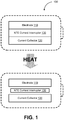
- FIG. 1 depicts a schematic diagram illustrating an example of a battery cell 100 having a negative thermal expansion component consistent with implementations of the current subject matter.
- the battery cell 100 can include an electrode 110 and a current collector 120.
- the electrode 110 can be an anode and/or a cathode of the battery cell 100.
- the battery cell 100 can include another current collector and another electrode having an opposite polarity as the electrode 110.
- the battery cell 100 includes a negative thermal expansion component.
- the negative thermal expansion component can be a negative thermal expansion current interrupter 130 interposed between the electrode 110 and the current collector 120.
- subjecting the battery cell 100 to heat can cause the negative thermal expansion current interrupter 130 to contract.
- the temperature of the battery cell 100 can increase when the battery cell 100 overcharges, overheats, and/or develops an internal short circuit.
- the negative thermal expansion current interrupter 130 responds to the increase in temperature by contracting.
- the negative thermal expansion current interrupter 130 can contract isotropically or uniformly in all directions.
- the negative thermal expansion current interrupter 130 can contract anisotropically or non-uniformly in different directions. It should be appreciated that the manner in which the negative thermal expansion current interrupter 130 contracts (e.g., isotropically and/or anisotropically) can depend on a design (e.g., dimensions, shape, and/or the like) of the negative thermal expansion current interrupter 130 and/or the materials used to form the negative thermal expansion current interrupter 130.
- the contraction of the negative thermal expansion current interrupter 130 forms a nonconductive gap between the electrode 110 and the current collector 120.
- the nonconductive gap can be formed when the contracting negative thermal expansion current interrupter 130 at least partially detaches from the electrode 110 and/or the current collector 120, thereby electrically decoupling the electrode 110 and the current collector 120.
- the nonconductive gap can be full and/or a partial gap between the electrode 110 and the current collector 120.
- the nonconductive gap can also be formed by gas and/or liquids released by the negative thermal expansion current interrupter 130.
- the nonconductive gap can be formed due a decomposition of the negative thermal expansion current interrupter 130. The presence of the nonconductive gap between the electrode 110 and the current collector 120 interrupts a flow of current through the battery cell 100, thereby neutralizing the risks associated with overcurrent.
- the negative thermal expansion current interrupter 130 can be formed from a material having negative thermal expansion properties including, for example, one or more oxides.
- the negative thermal expansion current interrupter 130 can be formed from a silicate (e.g., LiAlSiO 4 ( ⁇ - eucryptite), Li 2 Al 2 Si n O 4+2 n ( ⁇ -spodumenes), Mg 2 Al 4 Si 5 O 18 (cordierite), and/or the like), zirconium tungstate (e.g., ZrW 2 O 8 , ZrW 2 O 7 , and/or the like), cyanides (e.g., Cd(CN) 2 , ReO 3 , (HfMg)(WO 4 ) 3 , and/or the like), ruthenate (Ca 2 RuO 4 ⁇ y ), siliceous faujasite, Fe 3 Pt, perovskite oxides (e.g., nickel-based perovskite oxides (e.g
- the negative thermal expansion current interrupter 130 can be formed from a composite containing at least one negative thermal expansion material including, for example, ZrW 2 O 8 /copper, ZrW 2 O 8 /aluminum, ZrW 2 O 8 /phenolic resin, ZrW 2 O 8 /polyimide, ⁇ -eucryptite/copper, and/or the like.
- a composite containing at least one negative thermal expansion material including, for example, ZrW 2 O 8 /copper, ZrW 2 O 8 /aluminum, ZrW 2 O 8 /phenolic resin, ZrW 2 O 8 /polyimide, ⁇ -eucryptite/copper, and/or the like.
- FIG. 15 depicts a table 1500 illustrating examples of negative thermal expansion materials consistent with implementations of the current subject matter.
- the battery cell 100 can be a lithium (Li) ion battery.
- the negative thermal expansion current interrupter 130 can be formed by coating a mixture of 90% ScF 3 , 5% carbon black, and 5% polyvinylidene fluoride (PVDF) onto aluminum (Al) foil with a loading of 2 milligrams per square centimeter (mg/cm 2 ).
- the electrode 110 can be a lithium (e.g., LiCoO 2 ) cathode of the battery cell 110, which can be formed by coating a mixture of 5% plasma chemical vapor deposition (PCVD) and 5% carbon additive atop a ScF 3 surface.
- the electrode 110 can be a graphite (C) anode of the battery cell 100.
- FIG. 2 depicts a schematic diagram illustrating an example of the battery cell 100 having a negative thermal expansion component consistent with implementations of the current subject matter.
- the battery cell 100 can further include a separator 140 interposed between the two electrodes of the battery cell 100 including, for example, the electrode 110 and another electrode having an opposite polarity as the electrode 110.
- the electrode 110 can be an anode and/or a cathode of the battery cell 100.
- the battery cell 100 can include another electrode as well as a current collector coupled with of the two electrodes.
- the battery cell 100 includes the negative thermal expansion current interrupter 130.
- the negative thermal expansion current interrupter 130 can be interposed between the electrode 110 and the separator 140 instead of and/or in addition to being interposed between the electrode 110 and the current collector 120.
- subjecting the battery cell 100 to heat causes the negative thermal expansion current interrupter 130 to contract.
- the temperature of the battery cell 100 can increase when the battery cell 100 overcharges, overheats, and/or develops an internal short circuit.
- the negative thermal expansion current interrupter 130 can respond to the increase in temperature by contracting isotropically and/or anisotropically.
- the manner in which the negative thermal expansion current interrupter 130 contracts can depend on a design (e.g., dimensions, shape, and/or the like) of the negative thermal expansion current interrupter 130 and/or the materials used to form the negative thermal expansion current interrupter 130.
- the contraction of the negative thermal expansion current interrupter 130 can form a nonconductive gap between the electrode 110 and the separator 140.
- the nonconductive gap can be formed when the contracting negative thermal expansion current interrupter 130 at least partially detaches from the electrode 110 and/or the separator 140, thereby electrically decoupling the electrode 110 and the separator 140.
- the nonconductive gap can be a partial and/or a full gap between the electrode 110 and the separator 140.
- the nonconductive gap can also be formed by gas and/or liquids released by the negative thermal expansion current interrupter 130.
- the nonconductive gap can be formed due a decomposition of the negative thermal expansion current interrupter 130. The presence of the nonconductive gap between the electrode 110 and the separator 140 can interrupt a flow of current through the battery cell 100, thereby neutralizing the risks associated with overcurrent.
- the negative thermal expansion current interrupter 130 can be formed from a material having negative thermal expansion properties including, for example, one or more oxides.
- the negative thermal expansion current interrupter 130 can be formed from a silicate (e.g., LiAlSiO 4 ( ⁇ - eucryptite), Li 2 Al 2 Si n O 4+2 n ( ⁇ -spodumenes), Mg 2 Al 4 Si 5 O 18 (cordierite), and/or the like), zirconium tungstate (e.g., ZrW 2 O 8 , ZrW 2 O 7 , and/or the like), cyanides (e.g., Cd(CN) 2 , ReO 3 , (HfMg)(WO 4 ) 3 , and/or the like), ruthenate (Ca 2 RuO 4 ⁇ y ), siliceous faujasite, Fe 3 Pt, perovskite oxides (e.g., nickel-based perovskite oxides (e.g
- the negative thermal expansion current interrupter 130 can be formed from a composite containing at least one negative thermal expansion material including, for example, ZrW 2 O 8 /copper, ZrW 2 O 8 /aluminum, ZrW 2 O 8 /phenolic resin, ZrW 2 O 8 /polyimide, ⁇ -eucryptite/copper, and/or the like.
- a composite containing at least one negative thermal expansion material including, for example, ZrW 2 O 8 /copper, ZrW 2 O 8 /aluminum, ZrW 2 O 8 /phenolic resin, ZrW 2 O 8 /polyimide, ⁇ -eucryptite/copper, and/or the like.
- ZrW 2 O 8 /copper ZrW 2 O 8 /aluminum
- ZrW 2 O 8 /phenolic resin ZrW 2 O 8 /polyimide
- ⁇ -eucryptite/copper and/or the like.
- FIG. 3 depicts a schematic diagram illustrating an example of the battery cell 100 having a negative thermal expansion component consistent with implementations of the current subject matter.
- the battery cell 100 can further include another electrode 150 having an opposite polarity as the electrode 110.
- the negative thermal expansion component can include multiple negative thermal expansion current interrupters including, for example, the negative thermal expansion current interrupter 130 and another negative thermal expansion current interrupter 160.
- the battery cell 100 can include a separator interposed between the electrode 110 and the other electrode 150.
- the negative thermal expansion current interrupter 130 can be interposed between the electrode 110 and the current collector 120.
- the other negative thermal expansion current interrupter 160 can be interposed between the two electrodes of the battery cell 100 including, for example, the electrode 110 and the other electrode 150.
- subjecting the battery cell 100 to heat can cause the negative thermal expansion current interrupter 130 and/or the other negative thermal expansion current interrupter 160 to contract.
- the temperature of the battery cell 100 can increase when the battery cell 100 overcharges, overheats, and/or develops an internal short circuit.
- the negative thermal expansion current interrupter 130 and/or the other negative thermal expansion current interrupter 160 can respond to the increase in temperature by contracting isotropically and/or anisotropically.
- the manner in which the negative thermal expansion current interrupter 130 and/or the other negative thermal expansion current interrupter 160 contract can depend on a design (e.g., dimensions, shape, and/or the like) and/or the materials forming the the negative thermal expansion current interrupter 130 and/or the other negative thermal expansion current interrupter 160.
- the contraction of the negative thermal expansion current interrupter 160 can form a nonconductive gap between the electrode 110 and the other electrode 150.
- the other negative thermal expansion current interrupter 130 can also contract to form an additional nonconductive gap between the electrode 110 and the current collector 120.
- These nonconductive gaps can also be formed by gas and/or liquids released by the negative thermal expansion current interrupter 130.
- the nonconductive gaps can be formed due a decomposition of the negative thermal expansion current interrupter 130. The presence of the nonconductive gaps can interrupt a flow of current through the battery cell 100, thereby neutralizing the risks that arise when the battery cell 100 overcharges, overheats, and/or develops an internal short circuit.
- the negative thermal expansion current interrupter 130 and/or the other negative thermal expansion current interrupter 160 can be formed from a material having negative thermal expansion properties including, for example, one or more oxides.
- the negative thermal expansion current interrupter 130 can be formed from a silicate (e.g., LiAlSiO 4 ( ⁇ -eucryptite), Li 2 Al 2 Si n O 4+2 n ( ⁇ -spodumenes), Mg 2 Al 4 Si 5 O 18 (cordierite), and/or the like), zirconium tungstate (e.g., ZrW 2 O 8 , ZrW 2 O 7 , and/or the like), cyanides (e.g., Cd(CN) 2 , ReO 3 , (HfMg)(WO 4 ) 3 , and/or the like), ruthenate (Ca 2 RuO 4 ⁇ y ), siliceous faujasite, Fe 3 Pt, perovskite
- a silicate e.g
- the negative thermal expansion current interrupter 130 and/or the other negative thermal expansion current interrupter 160 can be formed from a composite containing at least one negative thermal expansion material including, for example, ZrW 2 O 8 /copper, ZrW 2 O 8 /aluminum, ZrW 2 O 8 /phenolic resin, ZrW 2 O 8 /polyimide, ⁇ -eucryptite/copper, and/or the like.
- a composite containing at least one negative thermal expansion material including, for example, ZrW 2 O 8 /copper, ZrW 2 O 8 /aluminum, ZrW 2 O 8 /phenolic resin, ZrW 2 O 8 /polyimide, ⁇ -eucryptite/copper, and/or the like.
- ZrW 2 O 8 /copper ZrW 2 O 8 /aluminum
- ZrW 2 O 8 /phenolic resin ZrW 2 O 8 /polyimide
- FIGS. 1-3 depicts a negative thermal expansion component that is integrated into an electric power system such as, for example, a battery cell, a battery pack, and/or the like.
- a negative thermal expansion component can also be implemented as a fuse, which can be coupled to an exterior and/or an interior of an electric power system.
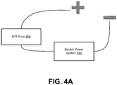
- FIG. 4A depicts a schematic diagram illustrating a negative thermal expansion fuse 400 coupled with an electric power system 450 consistent with implementations of the current subject matter. As shown in FIG. 4A , the negative thermal expansion fuse 400 can be coupled to a positive terminal of the electric power system 450.
- the negative thermal expansion fuse 400 can also be coupled to a negative terminal of the electric power system 450.
- the electric power system 450 can be any type of electric power system including, for example, a circuit, an electric appliance, an electric generator, an energy storage system, and/or the like.
- the electric power system 450 can be a battery, a converter (e.g., a DC/DC voltage converter, an AC/DC converter, a DC/AC converter, and/or the like), and/or the like.
- the negative thermal expansion fuse 400 can be installed between an electric generator (e.g, solar cell, solar panel, and/or the like) and an energy storage system containing rechargeable batteries, supercapacitors, flow batteries, fuel cells, and/or the like.
- FIG. 4B depicts a cross sectional view of an example of the negative thermal expansion fuse 400 consistent with implementations of the current subject matter.
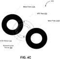
- FIG. 4C depicts an exploded view of an example of the negative thermal expansion fuse 400 consistent with implementations of the current subject matter.
- the negative thermal expansion fuse 400 can include a first metal plate 410A and a second metal plate 410B.
- the negative thermal expansion fuse 400 can include a negative thermal expansion plate 420 interposed between the first metal plate 410A and the second metal plate 410B.
- FIG. 4C depicts the negative thermal expansion fuse 400 as having an annular and/or disk configuration, it should be appreciated that the negative thermal expansion fuse 400 can have a different shape and/or configuration than shown including, for example, triangular, rectangular, and/or the like.
- the first metal plate 410A and/or the second metal plate 410B can be formed from a metal such as, for example, nickel (Ni) and/or the like.
- the negative thermal expansion plate 420 can be a hybrid negative thermal expansion component that includes a negative thermal expansion portion 422 and a nonconductive portion 424.
- the nonconductive portion 424 can be configured to provide structural support.
- the nonconductive portion 424 can be formed from any non-conducting material and/or non-conducting composite including, for example, non-conducting oxides (e.g., aluminum oxide, iron oxide, and/or the like), non-conducting ceramics (e.g., silicon oxide, boron glass, and/or the like), a non-conducting polymer (e.g., poly ethylene, polyvinylidene fluoride (PVDF), and/or the like), materials having a positive thermal coefficient (PTC), and/or the like.
- the nonconductive portion 424 of the negative thermal expansion plate 420 is formed from a positive temperature coefficient (PTC) material
- the nonconductive portion 424 can undergo a phase transition when subject to temperature exceeding a threshold value.
- the negative thermal expansion portion 422 can be formed from any material having negative thermal expansion properties including, for example, silicate (e.g., LiAlSiO 4 ( ⁇ -eucryptite), Li 2 Al 2 Si n O 4+2 n ( ⁇ -spodumenes), Mg 2 Al 4 Si 5 O 18 (cordierite), and/or the like), zirconium tungstate (e.g., ZrW 2 O 8 , ZrW 2 O 7 , and/or the like), cyanides (e.g., Cd(CN) 2 , ReO 3 , (HfMg)(WO 4 ) 3 , and/or the like), ruthenate (Ca 2 RuO 4 ⁇ y ), siliceous faujasite, Fe 3 Pt, perovskite oxides (e.g., nickel-based perovskite oxide Bi 0.95 La 0.05 NiO 3 and/or the like), antiperovskites (e.g., Ni 3 A
- the negative thermal expansion plate 420 can be formed from a composite containing at least one negative thermal expansion material including, for example, ZrW 2 O 8 /copper, ZrW 2 O 8 /aluminum, ZrW 2 O 8 /phenolic resin, ZrW 2 O 8 /polyimide, ⁇ -eucryptite/copper, and/or the like.
- table 1500 shown in FIG. 15 illustrates other examples of negative thermal expansion materials consistent with implementations of the current subject matter.
- the negative thermal expansion portion 422 of the negative thermal expansion plate 420 can contract when the negative thermal expansion fuse 400 is subject to heat.
- the nonconductive portion 424 includes a positive temperature coefficient (PTC) material
- the nonconductive portion 424 can undergo a phase transition when subject to temperature exceeding a threshold value.
- PTC positive temperature coefficient
- the nonconductive portion 424 can be formed from any positive temperature coefficient (PTC) material including, for example, poly ethylene, polyvinylidene fluoride (PVDF), acrylonitrile butadiene styrene (ABS) thermoplastic, glass and/or fiber-reinforced acrylonitrile butadiene styrene (ABS), acetal, amber, benzocyclobutene, cellulose acetate (CA), cellulose acetate butynate (CAB), cellulose nitrate (CN), chlorinated polyether, chlorinated polyvinylchloride (CPVC), ethylene ethyl acrylate (EEA), ethylene vinyl acetate (EVA), fluoroethylene propylene (FEP), fluorspar, CaF 2 , gutta percha, nylon molding and/or extruding compound, paraffin, polybutylene (PB), polyamide (PA), polyester, polypropylene (PP), and/or the like.
- PTC
- the negative thermal expansion fuse 400 can be exposed to increased temperatures due to excess heat generated by a larger than intended current flows through the electric power system 450.
- the negative thermal expansion portion 422 of the negative thermal expansion plate 420 can continue to contract as the temperature continues to increase.
- the nonconductive portion 424 of the negative thermal expansion plate 420 can undergo a phase transition once the temperature reaches a threshold value. It should be appreciated that this phase transition can include a solid to liquid phase transition, a solid to gas phase transition, a liquid to gas transition, and/or the like.
- the nonconductive portion 424 can expand as a result of undergoing the phase transition.
- the contraction of the negative thermal expansion portion 422 of the negative thermal expansion plate 420 can cause the negative thermal expansion plate 420 to at least partially detach from the first metal plate 410A and/or the second metal plate 410B, thereby creating a nonconductive gap between the first metal plate 410A and the second metal plate 410B.
- the expansion of the nonconductive portion 424 of the negative thermal expansion plate 420 can enlarge the nonconductive gap by further separating the negative thermal expansion plate 420 from the first metal plate 410A and/or the second metal plate 410B.
- the conductive gap between the first metal plate 410A and the second metal plate 410B can be a partial and/or a full gap.
- this nonconductive gap between the first metal plate 410A and the second metal plate 410B can serve as a circuit breaker interrupting the flow of current through the electric power system 450.
- the negative thermal expansion fuse 400 can eliminate the hazards that arise when the electric power system 450 is overheated, overcharged, and/or develops a short circuit.
- FIG. 5 depicts a schematic diagram illustrating another example of a hybrid negative thermal expansion component 500 consistent with implementations of the current subject matter.
- the hybrid negative thermal expansion component 500 can implement the negative thermal expansion current interrupter 130, the negative thermal expansion current interrupter 160, and/or the negative thermal expansion plate 420.
- the hybrid negative thermal expansion component 500 can include a phase transition layer 510 formed from a material that undergoes a phase transition when exposed to temperatures in excess of a threshold value.
- a phase transition layer 510 formed from a material that undergoes a phase transition when exposed to temperatures in excess of a threshold value.
- the phase transition layer 510 can undergo a solid to liquid phase transition, a solid to gas phase transition, a liquid to gas transition, and/or the like.
- the phase transition can cause the phase transition layer 510 to expand in response to temperatures in excess of the threshold value.
- the phase transition layer 510 can be formed from any material that responds to being exposed to temperatures in excess of the threshold value by undergoing a phase transition.
- the phase transition layer 510 can be formed from a positive temperature coefficient (PTC) material such as, for example, poly ethylene, polyvinylidene fluoride (PVDF), acrylonitrile butadiene styrene (ABS) thermoplastic, glass and/or fiber-reinforced acrylonitrile butadiene styrene (ABS), acetal, amber, benzocyclobutene, cellulose acetate (CA), cellulose acetate butynate (CAB), cellulose nitrate (CN), chlorinated polyether, chlorinated polyvinylchloride (CPVC), ethylene ethyl acrylate (EEA), ethylene vinyl acetate (EVA), fluoroethylene propylene (FEP), fluorspar, CaF 2 , gutta percha, nylon molding and/or extruding compound, paraffin, polybutylene (PB), polyamide (PA), polyester, polypropylene (PP), and/or the like.
- the phase transition layer 510 can be coupled with a negative thermal expansion layer 520.
- the negative thermal expansion layer 520 can be formed from a material having negative thermal expansion properties. As such, the negative thermal expansion layer 520 can contract when exposed to increasing temperatures. Furthermore, the contraction of the negative thermal expansion layer 520 can be continuous. That is, the negative thermal expansion layer 250 can continue to contract as the temperature continues to increase.
- the phase transition layer 510 can undergo a single discrete phase transition at the threshold temperature.
- the negative thermal expansion layer 520 can be interposed between the phase transition layer 510 and another phase transition layer 530.
- the phase transition layer 530 is optional.
- the hybrid negative thermal expansion component 500 can include multiple layers of phase transition material and negative thermal expansion material.
- the negative thermal expansion layer 520 can contract in response to increasing temperatures whereas the phase transition layer 510 and/or the phase transition layer 530 can expand when the temperature exceeds a threshold value. The contraction of the negative thermal expansion layer 520 can form a nonconductive gap, which can be further enlarged by the expansion of the phase transition layer 510 and/or the phase transition layer 530.
- FIG. 6 depicts as flowchart illustrating a process 600 for preparing an electrode layered with a negative thermal expansion material consistent with implementations of the current subject matter.
- the process 600 can be performed to form the negative thermal expansion current interrupter 130 on top of the electrode 110.
- the negative thermal expansion current interrupter 130 can be formed (602).
- the negative thermal expansion current interrupter 130 can be formed by dissolving a binder into a solvent.
- a conductive additive and a negative thermal expansion material can be added to the binder solution to form a slurry.
- the slurry can be coated onto a surface of a metal foil. Drying the slurry can result in the formation of the negative thermal expansion current interrupter 130 on the surface of the metal foil.
- the electrode 110 can be formed on top of the negative thermal expansion current interrupter 130 (604).
- the electrode 110 can be formed by dissolving a binder into a solvent.
- a conductive additive can be added to the binder solution to form a slurry.
- active electrode material can be added to the slurry before the slurry is coated onto the negative thermal expansion current interrupter 130 formed in operation 602 and compressed into a desired thickness.
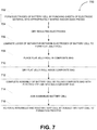
- FIG. 7 depicts a flowchart illustrating a process 700 for assembling a battery cell consistent with implementations of the current subject matter. Referring to FIGS. 1-3 and 6-7 , the process 600 can be performed to form the battery cell 100.
- the electrodes of the battery cell can be formed by punching sheets of electrode material into appropriately shaped and/or sized pieces (702). For instance, sheets of cathode material and/or anode material can be punched into appropriately shaped and/or sized pieces using an electrode tab. The resulting electrodes can be dried (704). For example, the cathode of the battery cell can be dried at 125°C for 10 hours while the anode of the battery cell can be dried at 140°C for 10 hours.
- a layer of separator can be laminated between the electrodes of the battery cell to form a flat jelly-roll (706).
- the flat jelly-roll can be placed in a composite bag (708).
- the flat jelly-roll formed in operation 706 can be placed inside an aluminum (Al) composite bag.
- the flat jelly-roll can be dried inside the composite bag (710).
- the flat jelly-roll inside the aluminum (Al) composite bag can be dried at 70°C for 10 hours.
- the composite bag can be filled with electrolyte and sealed to complete the assembly of the battery cell (712).
- the assembled battery cell can be aged (714).
- the battery cell formed in operation 712 can be aged for 36 hours.
- the assembled and aged battery cell can be activated by subjecting the battery cell to a formation process (716).
- the battery cell can undergo a formation process, which refers to a controlled charge and discharge cycle configured to activate the chemical components of the battery cell. This formation process can require the battery cell to be charged by being exposed to a gradually increasing current instead of a constant current such that the buildup of voltage within the battery cell is gradual. It should be appreciated that the battery cell can be ready for grading and/or use subsequent to the completion of the formation process.
- a battery cell having a negative thermal expansion component such as, for example, the battery cell 100 with the negative thermal expansion current interrupter 130 can be immune to the deleterious effects of overcharging, overheating, and/or internal short circuits.
- the negative thermal expansion component can contract in response to an increase in temperature, thereby forming one or more nonconductive gaps that interrupt the current flowing through the battery cell.
- FIGS. 9 and 12 show, a battery cell having a negative thermal expansion component can have comparable capacity as a battery without a negative thermal expansion component.
- including the negative thermal expansion component in the battery cell can prevent the battery cell from catching fire and/or exploding when subject to impact. For example, FIG.
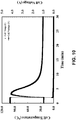
- FIG. 11 shows the battery cell having the negative thermal expansion component can withstand being overcharged without catching fire and/or exploding.
- FIG. 11 shows the voltage and the temperature of the overcharging battery cell spiking before tapering down and stabilizing after approximately 20 minutes, which indicates a rapid increase in the impedance within the battery cell at approximately the 20-minute mark.
- FIG. 13 shows the temperature of an overcharging reference cell without a negative thermal expansion component gradually increasing until spiking to over 400°C at the 48-minute mark, at which point the reference battery cell enters thermal runaway.
- FIG. 13 further shows the voltage of the reference battery cell as being relatively stable before spiking when the reference battery cell enters thermal runaway.
- the impedance of the reference battery cell did not increase to thwart the reference battery cell from entering thermal runaway.
- a battery cell's response to impact can be tested by charging the battery cell to 4.2 volts (V) with a 1-ampere current for 3 hours.
- the fully charged battery cell can be placed on a hard surface.
- a thermal couple can be attached to a surface of the battery cell while a voltage meter can be coupled to the positive terminal and the negative terminal of the battery cell.
- a steel rode measuring 15.8 millimeters in diameter and 70 millimeters in length can be positioned across the center of the batter cell.
- the battery cell can then be subject to impact from a 9.1 kilogram (kg) steel block that is suspended at and released from a height of 610 millimeters above the battery cell.
- the battery cell's voltage and temperature can be recorded after the steel block is released for a free fall onto the steel bar positioned across the battery cell.
- a containment tube having an interior diameter of 8 centimeters (cm) can be used to guide the steel block in its free fall.
- a battery cell can include a negative thermal expansion component such as, for example, a negative thermal expansion current interrupter, formed from a zirconium tungstate (e.g., ZrW 2 O 8 , ZrW 2 O 7 , and/or the like).
- the battery cell can include a lithium (Li) nickel cobalt manganese (NMC) oxide cathode and an anode formed from mesocarbon microbeads (MCMB).
- the process 600 can be performed in order to prepare an electrode layered with zirconium tungstate as the negative thermal expansion material while the process 700 can be performed to order to assembly the battery cell.
- the negative thermal expansion component of the battery cell can be formed by dissolving 0.5 grams of Torlon®4000TF (0.5 g) into 4.5 grams of N-methylpyrrolidone (NMP). Meanwhile, 3 grams of polyvinylidene fluoride (PVDF) can be dissolved into 34.5 grams of N-methylpyrrolidone (NMP).
- the Torlon®4000TF solution and the polyvinylidene fluoride (PVDF) solution can be combined with 0.2 grams of carbon black and mixed for 10 minutes at a rate of approximate 6500 revolutions per minute.
- nano zirconium tungstate powder e.g., ZrW 2 O 8 , ZrW 2 O 7 , and/or the like
- the resulting slurry can be coated onto one side of a 15 millimeter thick aluminum (Al) foil using an automatic coating machine with the first heat zone set to approximately 130°C and the second heat zone set to approximately 160°C.
- NMP N-methylpyrrolidone
- the cathode of the battery cell can be formed by dissolving 6 grams of polyvinylidene fluoride (PVDF) into 75 grams of N-methylpyrrolidone (NMP).
- PVDF polyvinylidene fluoride
- NMP N-methylpyrrolidone
- the resulting mixture can be combined with 6 grams of carbon black and mixed for 15 minutes at a rate of approximately 6500 revolutions per minute (rpm).
- 188 grams of nickel, manganese, and cobalt (NMC) can be added to the mixture and mixed for 30 minutes at a rate of approximately 6500 revolutions per minute (rmp).
- NMP N-methylpyrrolidone
- the resulting slurry can be coated onto the surface of the negative thermal expansion component using an automatic coating machine with the first heat zone set to about 85 °C and the second heat zone to about 135 °C .
- NMP N-methylpyrrolidone
- the final dried solid can have a loading (single side) of approximately 19.4 milligrams per square centimeter (mg/cm 2 ).
- the final dried solid can be compressed to a thickness of approximately 119 microns ( ⁇ m).
- the anode of the battery cell can be formed by dissolving 14 grams of carboxymethyl cellulose (CMC) into approximately 1077 grams of deionized water. The mixture can then be combined with 20 grams of carbon black and 8 gram of graphene before being mixed for 15 minutes at a rate of approximately 6500 revolutions per minute (rpm).
- the mixture can be further combined with 744.2 grams of mesocarbon microbeads (MCMB) and 140 grams of synthetic graphite (TIMCAL) and mixed for 30 minutes at a rate of approximately 6500 revolutions per minute (rpm).
- SBR styrene butadiene rubber
- Li neutralized polyimide 22 grams of styrene butadiene rubber (SBR) with a 50% solid content suspended in water and 3 grams of lithium neutralized polyimide can be added to the mixture and mixed for 5 minutes at approximately 6500 revolutions per minute (rpm).
- the viscosity of the resulting slurry can be adjusted before the slurry is coated onto a 9 millimeter thick copper (Cu) foil using an automatic coating machine with the first heat zone set to about 100°C and the second heat zone to about 130°C.
- the final dried solid can have a loading of approximately 11.2 milligrams per square centimeter (mg/cm 2 ).
- the final dried solid can be compressed to a thickness of approximately 170 microns ( ⁇ m).
- the battery cell can be assembled by forming the cathode and anode of the battery cell, for example, by punching sheets of the lithium (Li) nickel cobalt manganese (NMC) oxide cathode material and the mesocarbon microbead (MCMB) anode material into the appropriate shape and/or size using an electrode tab.
- the cathode can be dried at 125°C for 10 hours while the anode can be dried at 140°C for 10 hours.
- a separator can subsequently be laminated between the cathode and anode to form a flat jelly-roll.
- the flat jelly-roll can be placed into an aluminum (Al) composite bag and dried in a 70°C vacuum oven.
- the aluminum (Al) composite bag can be filled with an organic carbonate based electrolyte containing lithium hexafluorophosphate (LiPF 6 ), sealed, and aged for 16 hours.
- the assembled and aged battery cell can be subject to a formation process that includes a charge and discharge cycle.
- the battery cell can be charged to 4.2 volts first at a C-rate of 0.02C rate for 8 hours and then at a C-rate of 0.5C rate for 2 hours.
- the charged battery cell can be rested for 20 minutes before being discharged to 2.8 volts at a C-rate of 0.5C.
- the battery cell upon completing the formation process, can be punctured to release any gases that accumulated during the assembly process and resealed.
- the battery cell can then be ready for use and/or grading including, for example, impact testing, overcharge testing, discharge capacity testing, and/or the like.
- a reference battery cell can be formed to serve as a control sample providing baseline performance statistics.
- the reference battery cell can be formed without a negative thermal expansion component and can therefore lack overcurrent protection.
- the reference battery cell can include a lithium (Li) nickel cobalt manganese (NMC) oxide cathode and a mesocarbon microbead (MCMB) anode.
- the cathode of the reference battery cell can be formed by dissolving 21 grams of polyvinylidene fluoride (PVDF) into 262.5 grams of N-methylpyrrolidone (NMP). Furthermore, 8.4 grams of carbon black can be added to the solution and mixed for 15 minutes at a rate of approximately 6500 revolutions per minute (rpm). The mixture can be combined with 570.6 grams of nickel, manganese, and cobalt (NMC) and mixed for 30 minutes at a rate of approximately 6500 revolutions per minute to form a flowable slurry.
- PVDF polyvinylidene fluoride
- NMP N-methylpyrrolidone
- carbon black 8.4 grams of carbon black can be added to the solution and mixed for 15 minutes at a rate of approximately 6500 revolutions per minute (rpm).
- the mixture can be combined with 570.6 grams of nickel, manganese, and cobalt (NMC) and mixed for 30 minutes at a rate of approximately 6500 revolutions per minute to form a flowable slurry.
- NMP N-methylpyrrolidone
- the first heat zone of the automatic coating machine can be set to approximately 80°C and the second heat zone of the automatic coating machine can be set to approximately 130°C to evaporate the N-methylpyrrolidone (NMP) from the slurry coated onto the aluminum (Al) foil.
- the resulting dried solid which can have a loading of approximately 16.68 milligrams per square centimeter (mg/cm 2 ), can be compressed to a thickness of approximately 124 microns ( ⁇ m).
- the anode of the reference battery cell can be formed by dissolving 13 grams of carboxymethyl cellulose (CMC) into approximately 764 grams of deionized water. The mixture can then be combined with 20 grams of carbon black and mixed for 15 minutes at a rate of approximately 6500 revolutions per minute (rpm). Here, the mixture can be further combined with 757.28 grams of mesocarbon microbeads (MCMB) and 188.72 grams of synthetic graphite (TIMCAL) and mixed for 30 minutes at a rate of approximately 6500 revolutions per minute (rpm).
- CMC carboxymethyl cellulose
- TIMCAL synthetic graphite
- SBR styrene butadiene rubber
- Cu copper
- the final dried solid which can have a loading of approximately 11 milligrams per square centimeter (mg/cm 2 ), can be compressed to a thickness of approximately 149 microns ( ⁇ m).
- the reference battery cell can be assembled by forming the cathode and anode of the reference battery cell, for example, by punching sheets of the lithium (Li) nickel cobalt manganese (NMC) oxide cathode material and mesocarbon microbead (MCMB) anode material into the approximate shape and/or size using an electrode tab.
- the cathode can be dried at 125°C for 10 hours while the anode can be dried at 140°C for 10 hours.
- a separator can subsequently be laminated between the cathode and anode to form a flat jelly-roll.
- the flat jelly-roll can be placed into an aluminum (Al) composite bag and dried in a 70°C vacuum oven.
- the aluminum (Al) composite bag can be filled with an organic carbonate based electrolyte containing lithium hexafluorophosphate (LiPF 6 ), sealed, and aged for 16 hours.
- the assembled and aged battery cell can be subject to a formation process that includes a charge and discharge cycle.
- the reference battery cell can be charged to 4.2 volts first at a C-rate of 0.02C rate for 8 hours and then at a C-rate of 0.5C rate for 2 hours.
- the charged battery cell can be rested for 20 minutes before being discharged to 2.8 volts at a C-rate of 0.5C.
- the reference battery cell upon completing the formation process, can be punctured to release any gases that accumulated during the assembly process and resealed.
- the reference battery cell can then be ready for use and/or grading including, for example, impact testing, overcharge testing, discharge capacity testing, and/or the like.
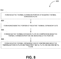
- FIG. 8 depicts a flowchart illustrating a process 800 for forming a negative thermal expansion fuse consistent with implementations of the current subject matter.
- the process 800 can be performed in order to form the negative thermal expansion fuse 400 which, as noted, includes the negative thermal expansion plate 420 interposed between the first metal plate 410A and the second metal plate 410B.
- the negative thermal expansion portion 422 of the negative thermal expansion plate 420 can be formed (802).
- the negative thermal expansion portion 422 can be formed by dissolving 0.05 grams of polyvinylidene fluoride (PVDF) into 6 grams of N-methylpyrrolidone (NMP).
- PVDF polyvinylidene fluoride
- NMP N-methylpyrrolidone
- the solution can be combined with 5 grams of a negative thermal expansion material and 1 gram of carbon black to form a paste.
- the paste can be dried at 100°C for 24 hours. It should be appreciated that the paste can be dried into any shape and/or configuration including, for example, annular, rectangular, and/or the like.
- the nonconductive portion 424 of the negative thermal expansion plate 420 can be formed (804).
- the nonconductive portion 424 can be formed by mixing 5 grams of wax with 5 grams of polyvinylidene fluoride (PVDF).
- PVDF polyvinylidene fluoride
- the nonconductive portion 424 can be formed to provide structural support and/or exhibit positive temperature coefficient (PTC) properties.
- the negative thermal expansion portion 422 and the nonconductive portion 424 can be compressed to form the negative thermal expansion plate 420 (806).
- the negative thermal expansion portion 422 and the nonconductive portion 424 can be loaded into a two-chamber die and compressed to form the negative thermal expansion plate 420.
- the negative thermal expansion fuse 400 can be formed by compressing the negative thermal expansion plate 420 between first metal plate 410A and the second metal plate 410B (808).
- the negative thermal expansion plate 420 can be interposed between the first metal plate 410A and the second metal plate 420, which can be nickel (Ni) plates having a thickness of approximately 0.2 millimeters (mm).
- the negative thermal expansion plate 420 interposed between the first metal plate 410A and the second metal plate 410B can be compressed at 60°C to form the negative thermal expansion fuse 400.
- the negative thermal expansion fuse 400 which can be formed by performing the process 800, can be integrated into an electric power system such as, for example, the electric power system 450.
- the negative thermal expansion fuse 400 can be coupled to an electric power system via an external connection.
- phrases such as "at least one of” or “one or more of” may occur followed by a conjunctive list of elements or features.
- the term “and/or” may also occur in a list of two or more elements or features. Unless otherwise implicitly or explicitly contradicted by the context in which it used, such a phrase is intended to mean any of the listed elements or features individually or any of the recited elements or features in combination with any of the other recited elements or features.
- the phrases “at least one of A and B;” “one or more of A and B;” and “A and/or B” are each intended to mean "A alone, B alone, or A and B together.”
- a similar interpretation is also intended for lists including three or more items.
- phrases “at least one of A, B, and C;” “one or more of A, B, and C;” and “A, B, and/or C” are each intended to mean “A alone, B alone, C alone, A and B together, A and C together, B and C together, or A and B and C together.”
- Use of the term “based on,” above and in the claims is intended to mean, “based at least in part on,” such that an unrecited feature or element is also permissible.
Landscapes
- Chemical & Material Sciences (AREA)
- Chemical Kinetics & Catalysis (AREA)
- Electrochemistry (AREA)
- General Chemical & Material Sciences (AREA)
- Engineering & Computer Science (AREA)
- Manufacturing & Machinery (AREA)
- Physics & Mathematics (AREA)
- Thermal Sciences (AREA)
- Materials Engineering (AREA)
- Sustainable Development (AREA)
- Sustainable Energy (AREA)
- Automation & Control Theory (AREA)
- Life Sciences & Earth Sciences (AREA)
- Cell Separators (AREA)
- Connection Of Batteries Or Terminals (AREA)
- Secondary Cells (AREA)
- Battery Electrode And Active Subsutance (AREA)
- Emergency Protection Circuit Devices (AREA)
Claims (17)
- Batterie (100), umfassend:
einen ersten Stromunterbrecher (130), der durch ein Material mit negativer Wärmeausdehnung gekennzeichnet ist, so dass sich der erste Stromunterbrecher als Reaktion auf einen Anstieg der Temperatur zusammenzieht, wobei das Zusammenziehen des ersten Stromunterbrechers einen nicht leitenden Spalt innerhalb der Batterie bildet und die Bildung des nicht leitenden Spalts einen Stromfluss innerhalb der Batterie unterbricht. - Batterie nach Anspruch 1, wobei die Batterie weiter eine erste Elektrode (110) umfasst, und wobei der erste Stromunterbrecher auf einer Oberfläche der ersten Elektrode angeordnet ist.
- Batterie nach Anspruch 2, wobei die Batterie weiter einen Stromabnehmer (120) umfasst, wobei der erste Stromunterbrecher zwischen der ersten Elektrode und dem Stromabnehmer angeordnet ist, und wobei die Bildung des nicht leitenden Spalts den Stromfluss zumindest durch elektrische Entkopplung der ersten Elektrode und des Stromabnehmers unterbricht.
- Batterie nach einem der Ansprüche 2 bis 3, wobei die Batterie weiter eine zweite Elektrode (150) und einen zweiten Stromunterbrecher (160) umfasst, wobei der zweite Stromunterbrecher zwischen der ersten Elektrode und der zweiten Elektrode angeordnet ist, wobei der zweite Unterbrecher das negative thermische Material umfasst, so dass sich der zweite Stromunterbrecher als Reaktion auf den Anstieg der Temperatur zusammenzieht, wobei das Zusammenziehen des zweiten Stromunterbrechers einen weiteren nicht leitenden Spalt innerhalb der Batterie bildet, und wobei die Bildung des weiteren nicht leitenden Spalts den Stromfluss zumindest durch elektrische Entkopplung der ersten Elektrode und der zweiten Elektrode weiter unterbricht.
- Batterie nach einem der Ansprüche 2 bis 4, wobei die Batterie weiter einen Separator (140) umfasst, wobei der Stromunterbrecher zwischen dem Separator und der ersten Elektrode angeordnet ist, und wobei die Bildung des nicht leitenden Spalts den Stromfluss zumindest durch elektrische Entkopplung des Separators und der ersten Elektrode unterbricht.
- Batterie nach einem der Ansprüche 1-5, wobei das Material mit negativer Wärmeausdehnung ein oder mehrere Oxide umfasst.
- Batterie nach einem der Ansprüche 1 bis 6, wobei das Material mit negativer Wärmeausdehnung ein Silikat, ein Zirkoniumwolframat, ein Cyanid, ein Ruthenat, einen silikatischen Faujasit, Fe3Pt, ein Perowskit-Oxid, einen Antiperowskit, ein Zeolith, ein Samariumfullerid, LaCu3Fe4O12, eine Invarlegierung, ein Metalloxid, ein niedrigdimensionales Material, ein Metallfluorid, ein mechanoresponsives Polymer, ein poröses Polyacrylamid, ein Dibenzocyclooctadien und/oder einen Dibenzocyclooctadien enthaltenden Polyacrylamidfilm umfasst.
- Batterie nach einem der Ansprüche 1-7, wobei das Material mit negativer Wärmeausdehnung ein Verbundmaterial aus einem oder mehreren Materialien mit negativer Wärmeausdehnung umfasst.
- Batterie nach einem der Ansprüche 1-8, wobei die erste Elektrode eine Kathode oder eine Anode der Batterie umfasst.
- Batterie nach einem der Ansprüche 1-9, wobei die erste Elektrode Lithium umfasst.
- Sicherung (400), umfassend:
eine erste Metallplatte (410A) und eine zweite Metallplatte (410B), und gekennzeichnet durch eine Platte (420) mit negativer Wärmeausdehnung, die zwischen der ersten Metallplatte und der zweiten Metallplatte angeordnet ist, wobei die Platte mit negativer Wärmeausdehnung ein Material mit negativer Wärmeausdehnung umfasst, so dass sich mindestens ein Teil der Platte mit negativer Wärmeausdehnung als Reaktion auf einen Anstieg der Temperatur zusammenzieht, wobei das Zusammenziehen der Platte mit negativer Wärmeausdehnung einen nicht leitenden Spalt zwischen der ersten Metallplatte und der zweiten Metallplatte bildet und die Bildung des nicht leitenden Spalts einen Stromfluss durch ein mit der Sicherung gekoppeltes elektrisches Energiesystem unterbricht. - Sicherung nach Anspruch 11, wobei die Platte mit negativer Wärmeausdehnung ein nichtleitendes Material (424) umfasst, das so ausgebildet ist, dass es strukturelle Unterstützung bietet.
- Sicherung nach Anspruch 12, wobei das nicht leitende Material ein Material mit positivem Temperaturkoeffizienten umfasst, so dass ein anderer Teil der Platte mit negativer Wärmeausdehnung als Reaktion auf eine Temperatur, die einen Schwellenwert überschreitet, einen Phasenübergang erfährt, wobei der Phasenübergang bewirkt, dass sich der andere Teil der Platte mit negativer Wärmeausdehnung ausdehnt, und wobei der nicht leitende Spalt weiter durch die Ausdehnung des anderen Teils der Platte mit negativer Wärmeausdehnung gebildet wird.
- Sicherung nach einem der Ansprüche 12-13, wobei das Material mit positivem Temperaturkoeffizienten Polyethylen, Polyvinylidenfluorid, Acrylnitril-Butadien-Styrol-Thermoplast, glas- und/oder faserverstärktes Acrylnitril-Butadien-Styrol, Acetal, Bernstein, Benzocyclobuten, Celluloseacetat, Celluloseacetatbutynat, Cellulosenitrat, chlorierten Polyether, chloriertes Polyvinylchlorid, Ethylenethylacrylat, Ethylenvinylacetat, Fluorethylenpropylen, Flussspat, CaF2, Guttapercha, Nylonform- und/oder -extrudierverbindung, Paraffin, Polybutylen, Polyamid, Polyester und/oder Polypropylen umfasst.
- Sicherung nach einem der Ansprüche 11-14, wobei das Material mit negativer Wärmeausdehnung ein oder mehrere Oxide umfasst.
- Sicherung nach einem der Ansprüche 11 bis 15, wobei das Material mit negativer Wärmeausdehnung ein Silikat, ein Zirkoniumwolframat, ein Cyanid, ein Ruthenat, einen siliziumhaltigen Faujasit, Fe3Pt, ein Perowskit-Oxid, einen Antiperowskit, ein Zeolith, ein Samariumfullerid, LaCu3Fe4O12, eine Invarlegierung, ein Metalloxid, ein niedrigdimensionales Material, ein Metallfluorid, ein mechanoresponsives Polymer, ein poröses Polyacrylamid, ein Dibenzocyclooctadien und/oder einen Dibenzocyclooctadien enthaltenden Polyacrylamidfilm umfasst.
- Sicherung nach einem der Ansprüche 11-16, wobei das Material mit negativer Wärmeausdehnung einen Verbundstoff aus einem oder mehreren Materialien mit negativer Wärmeausdehnung umfasst.
Priority Applications (2)
| Application Number | Priority Date | Filing Date | Title |
|---|---|---|---|
| EP22201960.6A EP4177993A3 (de) | 2017-05-01 | 2018-05-01 | Stromunterbrecher mit negativer thermischer ausdehnung |
| EP21151809.7A EP3869600B1 (de) | 2017-05-01 | 2018-05-01 | Stromversorgungssystem und sicherung aufweisend eine platte mit negativer wärmeausdehnung |
Applications Claiming Priority (2)
| Application Number | Priority Date | Filing Date | Title |
|---|---|---|---|
| US201762492827P | 2017-05-01 | 2017-05-01 | |
| PCT/US2018/030474 WO2018204379A1 (en) | 2017-05-01 | 2018-05-01 | Negative thermal expansion current interrupter |
Related Child Applications (3)
| Application Number | Title | Priority Date | Filing Date |
|---|---|---|---|
| EP21151809.7A Division-Into EP3869600B1 (de) | 2017-05-01 | 2018-05-01 | Stromversorgungssystem und sicherung aufweisend eine platte mit negativer wärmeausdehnung |
| EP21151809.7A Division EP3869600B1 (de) | 2017-05-01 | 2018-05-01 | Stromversorgungssystem und sicherung aufweisend eine platte mit negativer wärmeausdehnung |
| EP22201960.6A Division EP4177993A3 (de) | 2017-05-01 | 2018-05-01 | Stromunterbrecher mit negativer thermischer ausdehnung |
Publications (2)
| Publication Number | Publication Date |
|---|---|
| EP3619761A1 EP3619761A1 (de) | 2020-03-11 |
| EP3619761B1 true EP3619761B1 (de) | 2021-03-03 |
Family
ID=62563241
Family Applications (3)
| Application Number | Title | Priority Date | Filing Date |
|---|---|---|---|
| EP22201960.6A Pending EP4177993A3 (de) | 2017-05-01 | 2018-05-01 | Stromunterbrecher mit negativer thermischer ausdehnung |
| EP21151809.7A Active EP3869600B1 (de) | 2017-05-01 | 2018-05-01 | Stromversorgungssystem und sicherung aufweisend eine platte mit negativer wärmeausdehnung |
| EP18730156.9A Active EP3619761B1 (de) | 2017-05-01 | 2018-05-01 | Stromunterbrecher mit negativer wärmeausdehnung |
Family Applications Before (2)
| Application Number | Title | Priority Date | Filing Date |
|---|---|---|---|
| EP22201960.6A Pending EP4177993A3 (de) | 2017-05-01 | 2018-05-01 | Stromunterbrecher mit negativer thermischer ausdehnung |
| EP21151809.7A Active EP3869600B1 (de) | 2017-05-01 | 2018-05-01 | Stromversorgungssystem und sicherung aufweisend eine platte mit negativer wärmeausdehnung |
Country Status (4)
| Country | Link |
|---|---|
| US (3) | US10818906B2 (de) |
| EP (3) | EP4177993A3 (de) |
| CN (2) | CN117254070A (de) |
| WO (1) | WO2018204379A1 (de) |
Families Citing this family (14)
| Publication number | Priority date | Publication date | Assignee | Title |
|---|---|---|---|---|
| EP4177993A3 (de) | 2017-05-01 | 2023-06-07 | American Lithium Energy Corporation | Stromunterbrecher mit negativer thermischer ausdehnung |
| US10923727B2 (en) | 2017-07-28 | 2021-02-16 | American Lithium Energy Corporation | Anti-corrosion for battery current collector |
| WO2020005988A1 (en) | 2018-06-25 | 2020-01-02 | American Lithium Energy Corporation | Safety layer for battery cells |
| EP3641003A1 (de) * | 2018-10-17 | 2020-04-22 | Hilti Aktiengesellschaft | Pouchzelle |
| US20220156681A1 (en) * | 2020-11-13 | 2022-05-19 | DropZone.store LLC | Aerial delivery location identifier |
| KR102569103B1 (ko) * | 2020-11-18 | 2023-08-23 | 주식회사 유앤에스에너지 | 전극용 집전체 |
| FR3116670B1 (fr) * | 2020-11-25 | 2023-08-18 | Commissariat Energie Atomique | Dispositif d’alimentation électrique comprenant un actionneur thermosensible et appareil associé. |
| CN114479670A (zh) * | 2021-12-27 | 2022-05-13 | 牛墨石墨烯应用科技有限公司 | 一种石墨烯高分子中高温智热板及其制备方法 |
| EP4213272A1 (de) * | 2022-01-18 | 2023-07-19 | Amionx, Inc. | Zusammensetzung mit kleinmoleküligen additiven für verbesserte sicherheit und leistung in hochspannungsbatterien |
| EP4595128A1 (de) * | 2022-09-28 | 2025-08-06 | Amionx, Inc. | Wiederaufladbare batterie mit formgedächtnisschicht für erhöhte sicherheit |
| US12549066B2 (en) * | 2023-01-18 | 2026-02-10 | Cfd Research Corporation | Reverse convection power generation |
| CN116053410B (zh) * | 2023-03-30 | 2023-07-25 | 星恒电源股份有限公司 | 一种钠离子电池正极片、其制备方法及钠离子电池 |
| US12328848B2 (en) | 2023-06-12 | 2025-06-10 | Battelle Savannah River Alliance, Llc | Systems and methods for controlling heat transfer between components |
| CN120164957B (zh) * | 2025-03-21 | 2026-04-17 | 扬州纳力新材料科技有限公司 | 一种热安全型功能集流体及其制备方法、极片和电池 |
Family Cites Families (129)
| Publication number | Priority date | Publication date | Assignee | Title |
|---|---|---|---|---|
| US2664481A (en) * | 1951-11-14 | 1953-12-29 | Harry A Pearl | Thermal relay and constant gap spacer |
| US4035552A (en) * | 1976-07-23 | 1977-07-12 | Gte Laboratories Incorporated | Electrochemical cell |
| US4075400A (en) | 1977-02-04 | 1978-02-21 | Fritts David H | Over temperature battery deactivation system |
| US4397919A (en) * | 1979-03-22 | 1983-08-09 | Standard Oil Company | Explosion resistant battery cells |
| US4361799A (en) * | 1980-03-27 | 1982-11-30 | Raychem Corporation | Over-temperature sense and locate device |
| US4456631A (en) | 1983-04-19 | 1984-06-26 | Ford Motor Company | Electronically conductive lithia doped oxide ceramics for use in sodium sulfur batteries |
| US4541735A (en) * | 1984-12-24 | 1985-09-17 | General Motors Corporation | Thermal sensing element using methanol saturated fluorocarbon elastomer as the heat responsive material |
| US4855195A (en) * | 1988-07-11 | 1989-08-08 | Eveready Battery Company, Inc. | Electrochemical cell with internal circuit interrupter |
| CA2000873C (en) * | 1988-10-21 | 1999-12-14 | Shigeru Oishi | Cell having current cutoff valve |
| US4992339A (en) * | 1990-03-14 | 1991-02-12 | Eveready Battery Company, Inc. | Electrochemical cell with circuit disconnect device |
| JPH04212127A (ja) | 1990-04-03 | 1992-08-03 | Canon Inc | 液晶素子および表示装置 |
| US4975341A (en) * | 1990-04-03 | 1990-12-04 | Eveready Battery Company, Inc. | Electrochemical cell with circuit disconnect device |
| US5188909A (en) * | 1991-09-12 | 1993-02-23 | Eveready Battery Co., Inc. | Electrochemical cell with circuit disconnect device |
| WO1995001393A1 (en) | 1993-06-30 | 1995-01-12 | New Japan Chemical Co., Ltd. | Thermoplastic resin composition and process for molding the same |
| JPH07220755A (ja) | 1994-02-07 | 1995-08-18 | Tdk Corp | 積層型リチウム二次電池 |
| US5507842A (en) | 1994-02-28 | 1996-04-16 | At&T Corp. | Process for converting lead and lead oxides to barium metaplumbate |
| JP3261688B2 (ja) * | 1994-08-23 | 2002-03-04 | キヤノン株式会社 | 二次電池及びその製造方法 |
| JPH0920755A (ja) | 1995-07-03 | 1997-01-21 | Hokuriku Seiyaku Co Ltd | 両性型三環系化合物 |
| KR0158845B1 (ko) * | 1995-07-28 | 1999-02-18 | 배순훈 | 리튬건전지의 과부하 방지구조 |
| CA2163187C (en) | 1995-11-17 | 2003-04-15 | Huanyu Mao | Aromatic monomer gassing agents for protecting non-aqueous lithium batteries against overcharge |
| US5691073A (en) * | 1996-04-10 | 1997-11-25 | Duracell Inc. | Current interrupter for electrochemical cells |
| US5750277A (en) * | 1996-04-10 | 1998-05-12 | Texas Instruments Incorporated | Current interrupter for electrochemical cells |
| JPH09320568A (ja) | 1996-05-28 | 1997-12-12 | Toray Ind Inc | 非水電解液系二次電池 |
| US5754090A (en) * | 1996-07-19 | 1998-05-19 | Emerson Electric Co. | Thermostat having a temperature sensing element which includes a member having a negative coefficient of thermal expansion |
| CA2233390A1 (en) * | 1997-05-02 | 1998-11-02 | William F. Quinn | Thermal switch assembly |
| US6069551A (en) * | 1997-05-02 | 2000-05-30 | Therm-O-Disc, Incorporated | Thermal switch assembly |
| US6084501A (en) * | 1997-05-05 | 2000-07-04 | Therm-O-Disc Incorporated | Thermal cutoff switch |
| JPH1167274A (ja) | 1997-08-22 | 1999-03-09 | Daikin Ind Ltd | リチウム二次電池及び高分子ゲル電解質並びにリチウム二次電池用結着剤 |
| US6222439B1 (en) * | 1998-02-17 | 2001-04-24 | Sumitomo Wiring Systems, Ltd. | Circuit breaking device |
| JPH11260220A (ja) * | 1998-03-13 | 1999-09-24 | Uchiya Thermostat Kk | サーマルプロテクタ |
| JP2000164111A (ja) * | 1998-03-16 | 2000-06-16 | Yazaki Corp | 自動車用大電流ヒュ―ズ |
| JP4236308B2 (ja) | 1998-08-31 | 2009-03-11 | 三洋電機株式会社 | リチウムイオン電池 |
| US6181545B1 (en) | 1998-09-24 | 2001-01-30 | Telcordia Technologies, Inc. | Supercapacitor structure |
| US6018286A (en) * | 1998-11-20 | 2000-01-25 | Therm-O-Disc, Incorporated | Thermal switch |
| JP3516259B2 (ja) * | 1999-05-18 | 2004-04-05 | 矢崎総業株式会社 | 電源直付け用大電流ヒューズ |
| US6342826B1 (en) * | 1999-08-11 | 2002-01-29 | Therm-O-Disc, Incorporated | Pressure and temperature responsive switch assembly |
| JP2001210366A (ja) | 2000-01-26 | 2001-08-03 | Matsushita Electric Ind Co Ltd | 非水電気化学装置およびその電解液 |
| KR100337889B1 (ko) | 2000-06-22 | 2002-05-24 | 김순택 | 리튬 2차전지 |
| US6570749B1 (en) * | 2000-07-14 | 2003-05-27 | Advanced Battery Technology Ltd | Over-current and thermal protection device |
| EP1246276A3 (de) * | 2001-03-26 | 2004-01-14 | Wilson Greatbatch Ltd. | Verbindungsschmelzsicherung |
| JP3669429B2 (ja) | 2001-03-27 | 2005-07-06 | 信越化学工業株式会社 | 電極用組成物及び電極材 |
| DE10330568B4 (de) * | 2002-07-09 | 2008-01-24 | Sumitomo Wiring Systems, Ltd., Yokkaichi | Sicherungsbox |
| TW547865U (en) | 2002-07-12 | 2003-08-11 | Polytronics Technology Corp | Over-current protection device |
| KR100457626B1 (ko) | 2002-11-15 | 2004-11-17 | 삼성에스디아이 주식회사 | 이차전지용 안전장치와 이를 구비한 이차 전지 |
| GB0227705D0 (en) | 2002-11-27 | 2003-01-08 | Danionics As | Electrochemical cell |
| JP2005011540A (ja) | 2003-06-16 | 2005-01-13 | Toshiba Corp | 非水電解液二次電池 |
| TWI251359B (en) | 2003-10-10 | 2006-03-11 | Lg Cable Ltd | Lithium secondary battery having PTC powder and manufacturing method thereof |
| DE102004052476B4 (de) * | 2003-10-31 | 2007-08-09 | Yazaki Corp. | Sicherungsanordnung |
| JPWO2005046017A1 (ja) | 2003-11-07 | 2007-05-24 | タイコ エレクトロニクス レイケム株式会社 | 過熱防止デバイスおよびこれを備える電気装置 |
| TW200601656A (en) * | 2004-06-28 | 2006-01-01 | Ultralife Taiwan Inc | Battery protection device |
| WO2006052313A1 (en) | 2004-11-08 | 2006-05-18 | 3M Innovative Properties Company | Polyimide electrode binders |
| TWI338396B (en) | 2006-01-17 | 2011-03-01 | Lg Chemical Ltd | Additives for non-aqueous electrolyte and lithium secondary battery using the same |
| JP2007280803A (ja) | 2006-04-07 | 2007-10-25 | Teijin Ltd | ハイブリッド型積層電極、それを用いたハイブリッド二次電源 |
| KR100879892B1 (ko) | 2006-05-22 | 2009-01-21 | 주식회사 엘지화학 | 과충전시의 안전성 향상을 위한 전극을 포함하고 있는이차전지 |
| US20070269718A1 (en) | 2006-05-22 | 2007-11-22 | 3M Innovative Properties Company | Electrode composition, method of making the same, and lithium ion battery including the same |
| KR100899282B1 (ko) * | 2006-07-18 | 2009-05-27 | 주식회사 엘지화학 | 열수축 튜브를 이용한 안전 스위치 및 이를 포함하고 있는이차전지 |
| US8197719B2 (en) | 2006-11-17 | 2012-06-12 | American Lithium Energy Corp. | Electroactive agglomerated particles |
| JP5286817B2 (ja) | 2007-02-27 | 2013-09-11 | 住友化学株式会社 | セパレータ |
| JP2008243708A (ja) | 2007-03-28 | 2008-10-09 | Matsushita Electric Ind Co Ltd | 非水電解質二次電池および非水電解質二次電池の製造方法 |
| US20080254343A1 (en) | 2007-04-16 | 2008-10-16 | Eveready Battery Company, Inc. | Electrochemical cell with thermal current interrupting switch |
| US8383291B2 (en) | 2007-05-23 | 2013-02-26 | GM Global Technology Operations LLC | Three-dimensional hydrophilic porous structures for fuel cell plates |
| EP2019395B1 (de) | 2007-07-24 | 2011-09-14 | TDK Corporation | Mehrschichtbauteil und Herstellungsverfahren dafür |
| JP5490713B2 (ja) | 2007-11-29 | 2014-05-14 | エルジー・ケム・リミテッド | 安全性部材を使用するpcmを含むバッテリーパック |
| JP2010146726A (ja) | 2007-11-30 | 2010-07-01 | Kyoritsu Kagaku Sangyo Kk | 導電性組成物 |
| KR101084982B1 (ko) | 2008-10-14 | 2011-11-18 | 주식회사 엘지화학 | 신규한 구조의 이차전지 팩 |
| KR101009526B1 (ko) | 2008-12-10 | 2011-01-18 | 삼성에스디아이 주식회사 | 배터리 팩 |
| DE102008063136A1 (de) | 2008-12-24 | 2009-09-17 | Daimler Ag | Verfahren und Vorrichtung zum Schutz einer Lithium-Ionen-Batterie in einem Fahrzeug |
| KR101023104B1 (ko) | 2008-12-26 | 2011-03-24 | 에스비리모티브 주식회사 | 이차 전지 |
| KR101091228B1 (ko) | 2008-12-30 | 2011-12-07 | 주식회사 엘지화학 | 다공성 코팅층을 구비한 세퍼레이터 및 이를 구비한 전기화학소자 |
| US9413031B2 (en) | 2009-03-24 | 2016-08-09 | Lenovo (Singapore) Pte. Ltd. | Apparatus and system for an internal fuse in a battery cell |
| US8754740B2 (en) * | 2009-05-20 | 2014-06-17 | GM Global Technology Operations LLC | Circuit implement utilizing active material actuation |
| WO2010140653A1 (ja) | 2009-06-05 | 2010-12-09 | 株式会社村田製作所 | チタン酸バリウム系半導体磁器組成物およびチタン酸バリウム系半導体磁器素子 |
| KR101075343B1 (ko) | 2009-09-01 | 2011-10-19 | 삼성에스디아이 주식회사 | 이차전지 |
| US20110117403A1 (en) | 2009-11-17 | 2011-05-19 | Tesla Motors, Inc. | Battery Cell with a Center Pin Comprised of a Low Melting Point Material |
| KR101042847B1 (ko) | 2009-12-22 | 2011-06-17 | 삼성에스디아이 주식회사 | 이차전지 |
| JP2011138647A (ja) | 2009-12-28 | 2011-07-14 | Hitachi Ltd | 二次電池の保護回路 |
| JP2011181441A (ja) | 2010-03-03 | 2011-09-15 | Sony Corp | 円筒型非水電解質電池 |
| WO2012009803A1 (en) | 2010-07-22 | 2012-01-26 | Bathium Canada Inc | Current collecting terminal for electrochemical cells |
| KR101274839B1 (ko) | 2010-07-26 | 2013-06-13 | 삼성에스디아이 주식회사 | 리드 플레이트를 통해 배어셀의 열을 온도 감응 소자에 전달하는 이차 전지 |
| US8932739B2 (en) * | 2010-08-04 | 2015-01-13 | Tesla Motors, Inc. | Battery pack configuration to reduce hazards associated with internal short circuits |
| JP5858325B2 (ja) | 2010-09-03 | 2016-02-10 | 株式会社Gsユアサ | 電池 |
| JP5304757B2 (ja) | 2010-09-06 | 2013-10-02 | Tdk株式会社 | セラミック積層ptcサーミスタ |
| US9263731B2 (en) | 2010-11-12 | 2016-02-16 | A123 Systems Llc | High performance lithium or lithium ion cell |
| US8828570B2 (en) | 2011-06-29 | 2014-09-09 | Hewlett-Packard Development Company, L.P. | Battery temperature sensor |
| JP2014505335A (ja) | 2011-06-30 | 2014-02-27 | エルジー・ケム・リミテッド | 二次電池用電極組立体及びこれを含むリチウム二次電池 |
| FR2979149B1 (fr) | 2011-08-18 | 2014-05-30 | Cyril Charles | Dispositif de surveillance thermique des bornes d'un dispositif de connexion electrique |
| US9005786B2 (en) | 2011-10-21 | 2015-04-14 | GM Global Technology Operations LLC | Integrated cell voltage sense line fusing |
| US20130171502A1 (en) | 2011-12-29 | 2013-07-04 | Guorong Chen | Hybrid electrode and surface-mediated cell-based super-hybrid energy storage device containing same |
| CN103194161B (zh) | 2012-01-10 | 2015-07-15 | 万向电动汽车有限公司 | 用于锂离子电池热安全保护的正温度系数材料及其应用 |
| WO2013110468A2 (de) | 2012-01-26 | 2013-08-01 | Li-Tec Battery Gmbh | Elektrochemische energiewandlereinrichtung mit einem zellgehäuse, batterie mit zumindest zwei dieser elektrochemischen energiewandlereinrichtungen sowie verfahren zum herstellen einer elektrochemischen energiewandlereinrichtung |
| JP6008981B2 (ja) | 2012-02-07 | 2016-10-19 | エルジー・ケム・リミテッド | 新規な構造の二次電池 |
| US20150280241A1 (en) | 2012-09-28 | 2015-10-01 | Furukawa Electric Co., Ltd. | Collector, electrode structure, nonaqueous electrolyte battery, conductive filler, and electrical storage device |
| EP2922124B1 (de) | 2012-11-19 | 2017-06-21 | UACJ Corporation | Kollektor, elektrodenstruktur, elektrizitätsspeicherungskomponente und zusammensetzung für kollektoren |
| EP2922123A4 (de) | 2012-11-19 | 2016-06-15 | Furukawa Electric Co Ltd | Kollektor, elektrode, sekundärzelle und kondensator |
| CN104904050A (zh) | 2012-11-19 | 2015-09-09 | 株式会社Uacj | 集电体,电极结构体以及蓄电部件 |
| US10290879B2 (en) * | 2012-12-05 | 2019-05-14 | Intelligent Energy Limited | Microvalve |
| TWI550655B (zh) | 2012-12-24 | 2016-09-21 | 財團法人工業技術研究院 | 鋰離子電池及其電極結構 |
| JP6523609B2 (ja) | 2013-03-26 | 2019-06-05 | 株式会社東芝 | 非水電解質電池用電極、非水電解質二次電池及び電池パック |
| JP6413351B2 (ja) | 2013-06-19 | 2018-10-31 | 株式会社Gsユアサ | 蓄電素子 |
| JP5701343B2 (ja) | 2013-07-10 | 2015-04-15 | 株式会社田中化学研究所 | リチウム二次電池用正極活物質、正極および二次電池 |
| DE102013214448A1 (de) * | 2013-07-24 | 2015-01-29 | Robert Bosch Gmbh | Verfahren und Vorrichtung zur Erkennung einer Temperaturerhöhung in einer Vielzahl elektrochemischer Speicherzellen |
| CN104377328B (zh) | 2013-08-14 | 2019-09-13 | 三星Sdi株式会社 | 可再充电锂电池 |
| US9627722B1 (en) | 2013-09-16 | 2017-04-18 | American Lithium Energy Corporation | Positive temperature coefficient film, positive temperature coefficient electrode, positive temperature coefficient separator, and battery comprising the same |
| CN105594019A (zh) | 2013-09-30 | 2016-05-18 | 日立化成株式会社 | 锂离子二次电池用正极及使用其的锂离子二次电池 |
| US9502708B2 (en) | 2013-10-11 | 2016-11-22 | Ec Power, Llc | Ohmically modulated battery |
| US10033071B2 (en) | 2013-10-11 | 2018-07-24 | Ec Power, Llc | Ohmically modulated battery |
| WO2015060175A1 (ja) | 2013-10-23 | 2015-04-30 | 株式会社豊田自動織機 | 電流遮断装置を備えた蓄電装置 |
| JP6442966B2 (ja) | 2013-10-31 | 2018-12-26 | 株式会社村田製作所 | 二次電池、電池パック、電動車両、電力貯蔵システム、電動工具および電子機器 |
| JP6217974B2 (ja) | 2013-12-11 | 2017-10-25 | トヨタ自動車株式会社 | 非水電解質二次電池 |
| WO2015130649A1 (en) * | 2014-02-26 | 2015-09-03 | Labinal, Llc | Circuit interruption device employing shape memory alloy element |
| CN104078276B (zh) * | 2014-06-10 | 2017-06-06 | 华南理工大学 | 一种基于形状记忆合金的温控单元 |
| US9751427B2 (en) | 2014-09-03 | 2017-09-05 | Ford Global Technologies, Llc | Vehicle traction battery thermal conditioning |
| HUE068398T2 (hu) | 2014-11-25 | 2024-12-28 | American Lithium Energy Corp | Újratölthetõ akkumulátor belsõ áramkorlátozóval és megszakítóval |
| US10020487B2 (en) | 2014-11-25 | 2018-07-10 | American Lithium Energy Corporation | Rechargeable battery with voltage activated current interrupter |
| US20160149269A1 (en) | 2014-11-25 | 2016-05-26 | American Lithium Energy Corporation | Rechargeable battery with temperature activated current interrupter |
| US10020545B2 (en) | 2014-11-25 | 2018-07-10 | American Lithium Energy Corporation | Rechargeable battery with resistive layer for enhanced safety |
| US10396341B2 (en) | 2014-11-25 | 2019-08-27 | American Lithium Energy Corporation | Rechargeable battery with internal current limiter and interrupter |
| US9711774B2 (en) * | 2014-12-03 | 2017-07-18 | Nano And Advanced Materials Institute Limited | Lithium ion battery with thermal sensitive layer |
| JP6777388B2 (ja) | 2015-02-27 | 2020-10-28 | パナソニック株式会社 | 非水電解質二次電池 |
| US20160365613A1 (en) | 2015-06-09 | 2016-12-15 | American Lithium Energy Corporation | Battery and supercapacitor hybrid |
| JP6380307B2 (ja) | 2015-09-09 | 2018-08-29 | トヨタ自動車株式会社 | 電池用セパレータ |
| CN105304409A (zh) * | 2015-09-11 | 2016-02-03 | 中国科学院理化技术研究所 | 一种基于负热膨胀的热开关 |
| CN105140075A (zh) * | 2015-10-15 | 2015-12-09 | 中投仙能科技(苏州)有限公司 | 一种电池均衡主动温度保护开关及其控制方法 |
| JP2017130283A (ja) | 2016-01-18 | 2017-07-27 | トヨタ自動車株式会社 | 全固体電池 |
| EP3417497B1 (de) | 2016-02-19 | 2025-03-19 | American Lithium Energy Corporation | Verfahren zur herstellung einer batteriezelle |
| US10109843B2 (en) | 2016-08-17 | 2018-10-23 | Hong Kong Applied Science and Technology Research Institute Company Limited | Separator for a rechargeable battery |
| EP4177993A3 (de) | 2017-05-01 | 2023-06-07 | American Lithium Energy Corporation | Stromunterbrecher mit negativer thermischer ausdehnung |
| US10923727B2 (en) | 2017-07-28 | 2021-02-16 | American Lithium Energy Corporation | Anti-corrosion for battery current collector |
| US10700339B2 (en) * | 2017-09-09 | 2020-06-30 | Sateria Battery Innovation Group, Inc. | Method of manufacture of an energy storage device having an internal fuse |
-
2018
- 2018-05-01 EP EP22201960.6A patent/EP4177993A3/de active Pending
- 2018-05-01 EP EP21151809.7A patent/EP3869600B1/de active Active
- 2018-05-01 US US15/968,346 patent/US10818906B2/en active Active
- 2018-05-01 WO PCT/US2018/030474 patent/WO2018204379A1/en not_active Ceased
- 2018-05-01 EP EP18730156.9A patent/EP3619761B1/de active Active
- 2018-05-01 CN CN202311057612.XA patent/CN117254070A/zh active Pending
- 2018-05-01 CN CN201880028616.6A patent/CN110574198B/zh active Active
-
2020
- 2020-09-16 US US17/023,242 patent/US11842868B2/en active Active
-
2023
- 2023-11-07 US US18/504,003 patent/US20240071700A1/en active Pending
Non-Patent Citations (1)
| Title |
|---|
| None * |
Also Published As
| Publication number | Publication date |
|---|---|
| US11842868B2 (en) | 2023-12-12 |
| WO2018204379A1 (en) | 2018-11-08 |
| EP3619761A1 (de) | 2020-03-11 |
| EP4177993A3 (de) | 2023-06-07 |
| CN110574198A (zh) | 2019-12-13 |
| US20180315988A1 (en) | 2018-11-01 |
| EP3869600A1 (de) | 2021-08-25 |
| EP3869600B1 (de) | 2022-10-19 |
| EP4177993A2 (de) | 2023-05-10 |
| US20240071700A1 (en) | 2024-02-29 |
| CN117254070A (zh) | 2023-12-19 |
| US10818906B2 (en) | 2020-10-27 |
| US20200411836A1 (en) | 2020-12-31 |
| CN110574198B (zh) | 2023-09-12 |
Similar Documents
| Publication | Publication Date | Title |
|---|---|---|
| US20240071700A1 (en) | Negative thermal expansion current interrupter | |
| US20250385300A1 (en) | Rechargeable battery with voltage activated current interrupter | |
| CA2968859C (en) | Rechargeable battery with internal current limiter and interrupter | |
| JP5831557B2 (ja) | 非水電解質二次電池の製造方法 | |
| JP5093997B2 (ja) | 非水電解質二次電池及びその製造方法 | |
| US20210028506A1 (en) | Rechargeable battery with temperature activated current interrupter | |
| US20120169297A1 (en) | Secondary battery with a rapid charging capability | |
| JP7173121B2 (ja) | 高安全性・高エネルギー密度電池 | |
| CN101485034B (zh) | 锂二次电池 | |
| CN114824260A (zh) | 一种安全锂离子电池 | |
| CN107851765A (zh) | 锂离子二次电池 | |
| EP2774198A1 (de) | Kathodenaktivmaterial für überladungsschutz in lithiumsekundärbatterien | |
| KR20050035074A (ko) | 피.티.씨. 분말을 가지는 리튬 이차 전지 및 그 제조방법 | |
| US5747188A (en) | Battery with improved safety during mechanical abuse | |
| EP3576205B1 (de) | Stromspeicherelement mit wasserfreiem elektrolyt und verfahren zur herstellung davon | |
| JP6668876B2 (ja) | リチウムイオン二次電池の製造方法 | |
| HK40091884A (en) | Negative thermal expansion current interrupter | |
| HK40057505B (en) | Electrical power system and fuse with negative thermal expansion plate | |
| HK40057505A (en) | Electrical power system and fuse with negative thermal expansion plate | |
| HK40017703B (en) | Negative thermal expansion current interrupter | |
| HK40017703A (en) | Negative thermal expansion current interrupter | |
| JP2016072098A (ja) | リチウムイオン二次電池用電極 | |
| US20240274998A1 (en) | Negative thermal expansion based protective mechanisms for battery cells | |
| JP2007012496A (ja) | 非水電解質二次電池 | |
| JP2000311706A (ja) | 円筒形リチウムイオン電池 |
Legal Events
| Date | Code | Title | Description |
|---|---|---|---|
| STAA | Information on the status of an ep patent application or granted ep patent |
Free format text: STATUS: UNKNOWN |
|
| STAA | Information on the status of an ep patent application or granted ep patent |
Free format text: STATUS: THE INTERNATIONAL PUBLICATION HAS BEEN MADE |
|
| PUAI | Public reference made under article 153(3) epc to a published international application that has entered the european phase |
Free format text: ORIGINAL CODE: 0009012 |
|
| STAA | Information on the status of an ep patent application or granted ep patent |
Free format text: STATUS: REQUEST FOR EXAMINATION WAS MADE |
|
| 17P | Request for examination filed |
Effective date: 20191010 |
|
| AK | Designated contracting states |
Kind code of ref document: A1 Designated state(s): AL AT BE BG CH CY CZ DE DK EE ES FI FR GB GR HR HU IE IS IT LI LT LU LV MC MK MT NL NO PL PT RO RS SE SI SK SM TR |
|
| AX | Request for extension of the european patent |
Extension state: BA ME |
|
| REG | Reference to a national code |
Ref country code: DE Ref legal event code: R079 Ref document number: 602018013444 Country of ref document: DE Free format text: PREVIOUS MAIN CLASS: H01M0008047010 Ipc: H01H0037460000 |
|
| DAV | Request for validation of the european patent (deleted) | ||
| DAX | Request for extension of the european patent (deleted) | ||
| RIC1 | Information provided on ipc code assigned before grant |
Ipc: H01M 10/052 20100101ALN20200728BHEP Ipc: H01H 37/36 20060101ALN20200728BHEP Ipc: H01M 10/42 20060101ALI20200728BHEP Ipc: H01M 4/02 20060101ALN20200728BHEP Ipc: H01H 37/46 20060101AFI20200728BHEP Ipc: H01M 2/34 20060101ALI20200728BHEP |
|
| GRAP | Despatch of communication of intention to grant a patent |
Free format text: ORIGINAL CODE: EPIDOSNIGR1 |
|
| STAA | Information on the status of an ep patent application or granted ep patent |
Free format text: STATUS: GRANT OF PATENT IS INTENDED |
|
| REG | Reference to a national code |
Ref country code: HK Ref legal event code: DE Ref document number: 40017703 Country of ref document: HK |
|
| INTG | Intention to grant announced |
Effective date: 20200921 |
|
| GRAS | Grant fee paid |
Free format text: ORIGINAL CODE: EPIDOSNIGR3 |
|
| GRAA | (expected) grant |
Free format text: ORIGINAL CODE: 0009210 |
|
| STAA | Information on the status of an ep patent application or granted ep patent |
Free format text: STATUS: THE PATENT HAS BEEN GRANTED |
|
| AK | Designated contracting states |
Kind code of ref document: B1 Designated state(s): AL AT BE BG CH CY CZ DE DK EE ES FI FR GB GR HR HU IE IS IT LI LT LU LV MC MK MT NL NO PL PT RO RS SE SI SK SM TR |
|
| REG | Reference to a national code |
Ref country code: GB Ref legal event code: FG4D |
|
| REG | Reference to a national code |
Ref country code: CH Ref legal event code: EP Ref country code: AT Ref legal event code: REF Ref document number: 1368118 Country of ref document: AT Kind code of ref document: T Effective date: 20210315 |
|
| REG | Reference to a national code |
Ref country code: DE Ref legal event code: R096 Ref document number: 602018013444 Country of ref document: DE |
|
| REG | Reference to a national code |
Ref country code: IE Ref legal event code: FG4D |
|
| REG | Reference to a national code |
Ref country code: NL Ref legal event code: FP |
|
| REG | Reference to a national code |
Ref country code: LT Ref legal event code: MG9D |
|
| PG25 | Lapsed in a contracting state [announced via postgrant information from national office to epo] |
Ref country code: BG Free format text: LAPSE BECAUSE OF FAILURE TO SUBMIT A TRANSLATION OF THE DESCRIPTION OR TO PAY THE FEE WITHIN THE PRESCRIBED TIME-LIMIT Effective date: 20210603 Ref country code: FI Free format text: LAPSE BECAUSE OF FAILURE TO SUBMIT A TRANSLATION OF THE DESCRIPTION OR TO PAY THE FEE WITHIN THE PRESCRIBED TIME-LIMIT Effective date: 20210303 Ref country code: GR Free format text: LAPSE BECAUSE OF FAILURE TO SUBMIT A TRANSLATION OF THE DESCRIPTION OR TO PAY THE FEE WITHIN THE PRESCRIBED TIME-LIMIT Effective date: 20210604 Ref country code: HR Free format text: LAPSE BECAUSE OF FAILURE TO SUBMIT A TRANSLATION OF THE DESCRIPTION OR TO PAY THE FEE WITHIN THE PRESCRIBED TIME-LIMIT Effective date: 20210303 Ref country code: LT Free format text: LAPSE BECAUSE OF FAILURE TO SUBMIT A TRANSLATION OF THE DESCRIPTION OR TO PAY THE FEE WITHIN THE PRESCRIBED TIME-LIMIT Effective date: 20210303 Ref country code: NO Free format text: LAPSE BECAUSE OF FAILURE TO SUBMIT A TRANSLATION OF THE DESCRIPTION OR TO PAY THE FEE WITHIN THE PRESCRIBED TIME-LIMIT Effective date: 20210603 |
|
| REG | Reference to a national code |
Ref country code: AT Ref legal event code: MK05 Ref document number: 1368118 Country of ref document: AT Kind code of ref document: T Effective date: 20210303 |
|
| PG25 | Lapsed in a contracting state [announced via postgrant information from national office to epo] |
Ref country code: RS Free format text: LAPSE BECAUSE OF FAILURE TO SUBMIT A TRANSLATION OF THE DESCRIPTION OR TO PAY THE FEE WITHIN THE PRESCRIBED TIME-LIMIT Effective date: 20210303 Ref country code: PL Free format text: LAPSE BECAUSE OF FAILURE TO SUBMIT A TRANSLATION OF THE DESCRIPTION OR TO PAY THE FEE WITHIN THE PRESCRIBED TIME-LIMIT Effective date: 20210303 Ref country code: LV Free format text: LAPSE BECAUSE OF FAILURE TO SUBMIT A TRANSLATION OF THE DESCRIPTION OR TO PAY THE FEE WITHIN THE PRESCRIBED TIME-LIMIT Effective date: 20210303 Ref country code: SE Free format text: LAPSE BECAUSE OF FAILURE TO SUBMIT A TRANSLATION OF THE DESCRIPTION OR TO PAY THE FEE WITHIN THE PRESCRIBED TIME-LIMIT Effective date: 20210303 |
|
| PG25 | Lapsed in a contracting state [announced via postgrant information from national office to epo] |
Ref country code: SM Free format text: LAPSE BECAUSE OF FAILURE TO SUBMIT A TRANSLATION OF THE DESCRIPTION OR TO PAY THE FEE WITHIN THE PRESCRIBED TIME-LIMIT Effective date: 20210303 Ref country code: AT Free format text: LAPSE BECAUSE OF FAILURE TO SUBMIT A TRANSLATION OF THE DESCRIPTION OR TO PAY THE FEE WITHIN THE PRESCRIBED TIME-LIMIT Effective date: 20210303 Ref country code: EE Free format text: LAPSE BECAUSE OF FAILURE TO SUBMIT A TRANSLATION OF THE DESCRIPTION OR TO PAY THE FEE WITHIN THE PRESCRIBED TIME-LIMIT Effective date: 20210303 Ref country code: CZ Free format text: LAPSE BECAUSE OF FAILURE TO SUBMIT A TRANSLATION OF THE DESCRIPTION OR TO PAY THE FEE WITHIN THE PRESCRIBED TIME-LIMIT Effective date: 20210303 |
|
| PG25 | Lapsed in a contracting state [announced via postgrant information from national office to epo] |
Ref country code: IS Free format text: LAPSE BECAUSE OF FAILURE TO SUBMIT A TRANSLATION OF THE DESCRIPTION OR TO PAY THE FEE WITHIN THE PRESCRIBED TIME-LIMIT Effective date: 20210703 Ref country code: SK Free format text: LAPSE BECAUSE OF FAILURE TO SUBMIT A TRANSLATION OF THE DESCRIPTION OR TO PAY THE FEE WITHIN THE PRESCRIBED TIME-LIMIT Effective date: 20210303 Ref country code: PT Free format text: LAPSE BECAUSE OF FAILURE TO SUBMIT A TRANSLATION OF THE DESCRIPTION OR TO PAY THE FEE WITHIN THE PRESCRIBED TIME-LIMIT Effective date: 20210705 Ref country code: RO Free format text: LAPSE BECAUSE OF FAILURE TO SUBMIT A TRANSLATION OF THE DESCRIPTION OR TO PAY THE FEE WITHIN THE PRESCRIBED TIME-LIMIT Effective date: 20210303 |
|
| REG | Reference to a national code |
Ref country code: DE Ref legal event code: R097 Ref document number: 602018013444 Country of ref document: DE |
|
| PLBE | No opposition filed within time limit |
Free format text: ORIGINAL CODE: 0009261 |
|
| STAA | Information on the status of an ep patent application or granted ep patent |
Free format text: STATUS: NO OPPOSITION FILED WITHIN TIME LIMIT |
|
| PG25 | Lapsed in a contracting state [announced via postgrant information from national office to epo] |
Ref country code: ES Free format text: LAPSE BECAUSE OF FAILURE TO SUBMIT A TRANSLATION OF THE DESCRIPTION OR TO PAY THE FEE WITHIN THE PRESCRIBED TIME-LIMIT Effective date: 20210303 Ref country code: DK Free format text: LAPSE BECAUSE OF FAILURE TO SUBMIT A TRANSLATION OF THE DESCRIPTION OR TO PAY THE FEE WITHIN THE PRESCRIBED TIME-LIMIT Effective date: 20210303 Ref country code: AL Free format text: LAPSE BECAUSE OF FAILURE TO SUBMIT A TRANSLATION OF THE DESCRIPTION OR TO PAY THE FEE WITHIN THE PRESCRIBED TIME-LIMIT Effective date: 20210303 Ref country code: MC Free format text: LAPSE BECAUSE OF FAILURE TO SUBMIT A TRANSLATION OF THE DESCRIPTION OR TO PAY THE FEE WITHIN THE PRESCRIBED TIME-LIMIT Effective date: 20210303 Ref country code: LU Free format text: LAPSE BECAUSE OF NON-PAYMENT OF DUE FEES Effective date: 20210501 |
|
| 26N | No opposition filed |
Effective date: 20211206 |
|
| REG | Reference to a national code |
Ref country code: BE Ref legal event code: MM Effective date: 20210531 |
|
| PG25 | Lapsed in a contracting state [announced via postgrant information from national office to epo] |
Ref country code: SI Free format text: LAPSE BECAUSE OF FAILURE TO SUBMIT A TRANSLATION OF THE DESCRIPTION OR TO PAY THE FEE WITHIN THE PRESCRIBED TIME-LIMIT Effective date: 20210303 |
|
| PG25 | Lapsed in a contracting state [announced via postgrant information from national office to epo] |
Ref country code: IE Free format text: LAPSE BECAUSE OF NON-PAYMENT OF DUE FEES Effective date: 20210501 |
|
| PG25 | Lapsed in a contracting state [announced via postgrant information from national office to epo] |
Ref country code: IS Free format text: LAPSE BECAUSE OF FAILURE TO SUBMIT A TRANSLATION OF THE DESCRIPTION OR TO PAY THE FEE WITHIN THE PRESCRIBED TIME-LIMIT Effective date: 20210703 |
|
| PG25 | Lapsed in a contracting state [announced via postgrant information from national office to epo] |
Ref country code: BE Free format text: LAPSE BECAUSE OF NON-PAYMENT OF DUE FEES Effective date: 20210531 |
|
| PG25 | Lapsed in a contracting state [announced via postgrant information from national office to epo] |
Ref country code: CY Free format text: LAPSE BECAUSE OF FAILURE TO SUBMIT A TRANSLATION OF THE DESCRIPTION OR TO PAY THE FEE WITHIN THE PRESCRIBED TIME-LIMIT Effective date: 20210303 |
|
| PG25 | Lapsed in a contracting state [announced via postgrant information from national office to epo] |
Ref country code: HU Free format text: LAPSE BECAUSE OF FAILURE TO SUBMIT A TRANSLATION OF THE DESCRIPTION OR TO PAY THE FEE WITHIN THE PRESCRIBED TIME-LIMIT; INVALID AB INITIO Effective date: 20180501 |
|
| PG25 | Lapsed in a contracting state [announced via postgrant information from national office to epo] |
Ref country code: MK Free format text: LAPSE BECAUSE OF FAILURE TO SUBMIT A TRANSLATION OF THE DESCRIPTION OR TO PAY THE FEE WITHIN THE PRESCRIBED TIME-LIMIT Effective date: 20210303 |
|
| PG25 | Lapsed in a contracting state [announced via postgrant information from national office to epo] |
Ref country code: MT Free format text: LAPSE BECAUSE OF FAILURE TO SUBMIT A TRANSLATION OF THE DESCRIPTION OR TO PAY THE FEE WITHIN THE PRESCRIBED TIME-LIMIT Effective date: 20210303 |
|
| PGFP | Annual fee paid to national office [announced via postgrant information from national office to epo] |
Ref country code: NL Payment date: 20250317 Year of fee payment: 8 |
|
| PGFP | Annual fee paid to national office [announced via postgrant information from national office to epo] |
Ref country code: FR Payment date: 20250310 Year of fee payment: 8 |
|
| PGFP | Annual fee paid to national office [announced via postgrant information from national office to epo] |
Ref country code: GB Payment date: 20250313 Year of fee payment: 8 |
|
| PGFP | Annual fee paid to national office [announced via postgrant information from national office to epo] |
Ref country code: DE Payment date: 20250305 Year of fee payment: 8 |
|
| PGFP | Annual fee paid to national office [announced via postgrant information from national office to epo] |
Ref country code: IT Payment date: 20250422 Year of fee payment: 8 |
|
| PGFP | Annual fee paid to national office [announced via postgrant information from national office to epo] |
Ref country code: CH Payment date: 20250601 Year of fee payment: 8 |
|
| PG25 | Lapsed in a contracting state [announced via postgrant information from national office to epo] |
Ref country code: TR Free format text: LAPSE BECAUSE OF FAILURE TO SUBMIT A TRANSLATION OF THE DESCRIPTION OR TO PAY THE FEE WITHIN THE PRESCRIBED TIME-LIMIT Effective date: 20210303 |