EP3620253B1 - Poröse werkzeuge und verfahren zur herstellung davon - Google Patents
Poröse werkzeuge und verfahren zur herstellung davon Download PDFInfo
- Publication number
- EP3620253B1 EP3620253B1 EP19192360.6A EP19192360A EP3620253B1 EP 3620253 B1 EP3620253 B1 EP 3620253B1 EP 19192360 A EP19192360 A EP 19192360A EP 3620253 B1 EP3620253 B1 EP 3620253B1
- Authority
- EP
- European Patent Office
- Prior art keywords
- porous
- layer
- array
- tool
- mold body
- Prior art date
- Legal status (The legal status is an assumption and is not a legal conclusion. Google has not performed a legal analysis and makes no representation as to the accuracy of the status listed.)
- Active
Links
Images


Classifications
-
- B—PERFORMING OPERATIONS; TRANSPORTING
- B23—MACHINE TOOLS; METAL-WORKING NOT OTHERWISE PROVIDED FOR
- B23K—SOLDERING OR UNSOLDERING; WELDING; CLADDING OR PLATING BY SOLDERING OR WELDING; CUTTING BY APPLYING HEAT LOCALLY, e.g. FLAME CUTTING; WORKING BY LASER BEAM
- B23K9/00—Arc welding or cutting
- B23K9/04—Welding for other purposes than joining, e.g. built-up welding
-
- B—PERFORMING OPERATIONS; TRANSPORTING
- B23—MACHINE TOOLS; METAL-WORKING NOT OTHERWISE PROVIDED FOR
- B23K—SOLDERING OR UNSOLDERING; WELDING; CLADDING OR PLATING BY SOLDERING OR WELDING; CUTTING BY APPLYING HEAT LOCALLY, e.g. FLAME CUTTING; WORKING BY LASER BEAM
- B23K26/00—Working by laser beam, e.g. welding, cutting or boring
- B23K26/36—Removing material
- B23K26/362—Laser etching
-
- B—PERFORMING OPERATIONS; TRANSPORTING
- B22—CASTING; POWDER METALLURGY
- B22F—WORKING METALLIC POWDER; MANUFACTURE OF ARTICLES FROM METALLIC POWDER; MAKING METALLIC POWDER; APPARATUS OR DEVICES SPECIALLY ADAPTED FOR METALLIC POWDER
- B22F10/00—Additive manufacturing of workpieces or articles from metallic powder
- B22F10/20—Direct sintering or melting
- B22F10/25—Direct deposition of metal particles, e.g. direct metal deposition [DMD] or laser engineered net shaping [LENS]
-
- B—PERFORMING OPERATIONS; TRANSPORTING
- B22—CASTING; POWDER METALLURGY
- B22F—WORKING METALLIC POWDER; MANUFACTURE OF ARTICLES FROM METALLIC POWDER; MAKING METALLIC POWDER; APPARATUS OR DEVICES SPECIALLY ADAPTED FOR METALLIC POWDER
- B22F5/00—Manufacture of workpieces or articles from metallic powder characterised by the special shape of the product
- B22F5/007—Manufacture of workpieces or articles from metallic powder characterised by the special shape of the product of moulds
-
- B—PERFORMING OPERATIONS; TRANSPORTING
- B22—CASTING; POWDER METALLURGY
- B22F—WORKING METALLIC POWDER; MANUFACTURE OF ARTICLES FROM METALLIC POWDER; MAKING METALLIC POWDER; APPARATUS OR DEVICES SPECIALLY ADAPTED FOR METALLIC POWDER
- B22F5/00—Manufacture of workpieces or articles from metallic powder characterised by the special shape of the product
- B22F5/009—Manufacture of workpieces or articles from metallic powder characterised by the special shape of the product of turbine components other than turbine blades
-
- B—PERFORMING OPERATIONS; TRANSPORTING
- B23—MACHINE TOOLS; METAL-WORKING NOT OTHERWISE PROVIDED FOR
- B23K—SOLDERING OR UNSOLDERING; WELDING; CLADDING OR PLATING BY SOLDERING OR WELDING; CUTTING BY APPLYING HEAT LOCALLY, e.g. FLAME CUTTING; WORKING BY LASER BEAM
- B23K10/00—Welding or cutting by means of a plasma
- B23K10/02—Plasma welding
- B23K10/027—Welding for purposes other than joining, e.g. build-up welding
-
- B—PERFORMING OPERATIONS; TRANSPORTING
- B23—MACHINE TOOLS; METAL-WORKING NOT OTHERWISE PROVIDED FOR
- B23K—SOLDERING OR UNSOLDERING; WELDING; CLADDING OR PLATING BY SOLDERING OR WELDING; CUTTING BY APPLYING HEAT LOCALLY, e.g. FLAME CUTTING; WORKING BY LASER BEAM
- B23K11/00—Resistance welding; Severing by resistance heating
- B23K11/0013—Resistance welding; Severing by resistance heating welding for purposes other than joining, e.g. build-up welding
-
- B—PERFORMING OPERATIONS; TRANSPORTING
- B23—MACHINE TOOLS; METAL-WORKING NOT OTHERWISE PROVIDED FOR
- B23K—SOLDERING OR UNSOLDERING; WELDING; CLADDING OR PLATING BY SOLDERING OR WELDING; CUTTING BY APPLYING HEAT LOCALLY, e.g. FLAME CUTTING; WORKING BY LASER BEAM
- B23K15/00—Electron-beam welding or cutting
- B23K15/0046—Welding
- B23K15/0086—Welding welding for purposes other than joining, e.g. build-up welding
-
- B—PERFORMING OPERATIONS; TRANSPORTING
- B23—MACHINE TOOLS; METAL-WORKING NOT OTHERWISE PROVIDED FOR
- B23K—SOLDERING OR UNSOLDERING; WELDING; CLADDING OR PLATING BY SOLDERING OR WELDING; CUTTING BY APPLYING HEAT LOCALLY, e.g. FLAME CUTTING; WORKING BY LASER BEAM
- B23K20/00—Non-electric welding by applying impact or other pressure, with or without the application of heat, e.g. cladding or plating
- B23K20/12—Non-electric welding by applying impact or other pressure, with or without the application of heat, e.g. cladding or plating the heat being generated by friction; Friction welding
- B23K20/1215—Non-electric welding by applying impact or other pressure, with or without the application of heat, e.g. cladding or plating the heat being generated by friction; Friction welding for other purposes than joining, e.g. built-up welding
-
- B—PERFORMING OPERATIONS; TRANSPORTING
- B23—MACHINE TOOLS; METAL-WORKING NOT OTHERWISE PROVIDED FOR
- B23K—SOLDERING OR UNSOLDERING; WELDING; CLADDING OR PLATING BY SOLDERING OR WELDING; CUTTING BY APPLYING HEAT LOCALLY, e.g. FLAME CUTTING; WORKING BY LASER BEAM
- B23K26/00—Working by laser beam, e.g. welding, cutting or boring
- B23K26/34—Laser welding for purposes other than joining
- B23K26/342—Build-up welding
-
- B—PERFORMING OPERATIONS; TRANSPORTING
- B23—MACHINE TOOLS; METAL-WORKING NOT OTHERWISE PROVIDED FOR
- B23K—SOLDERING OR UNSOLDERING; WELDING; CLADDING OR PLATING BY SOLDERING OR WELDING; CUTTING BY APPLYING HEAT LOCALLY, e.g. FLAME CUTTING; WORKING BY LASER BEAM
- B23K26/00—Working by laser beam, e.g. welding, cutting or boring
- B23K26/36—Removing material
-
- C—CHEMISTRY; METALLURGY
- C23—COATING METALLIC MATERIAL; COATING MATERIAL WITH METALLIC MATERIAL; CHEMICAL SURFACE TREATMENT; DIFFUSION TREATMENT OF METALLIC MATERIAL; COATING BY VACUUM EVAPORATION, BY SPUTTERING, BY ION IMPLANTATION OR BY CHEMICAL VAPOUR DEPOSITION, IN GENERAL; INHIBITING CORROSION OF METALLIC MATERIAL OR INCRUSTATION IN GENERAL
- C23C—COATING METALLIC MATERIAL; COATING MATERIAL WITH METALLIC MATERIAL; SURFACE TREATMENT OF METALLIC MATERIAL BY DIFFUSION INTO THE SURFACE, BY CHEMICAL CONVERSION OR SUBSTITUTION; COATING BY VACUUM EVAPORATION, BY SPUTTERING, BY ION IMPLANTATION OR BY CHEMICAL VAPOUR DEPOSITION, IN GENERAL
- C23C14/00—Coating by vacuum evaporation, by sputtering or by ion implantation of the coating forming material
- C23C14/22—Coating by vacuum evaporation, by sputtering or by ion implantation of the coating forming material characterised by the process of coating
- C23C14/50—Substrate holders
-
- C—CHEMISTRY; METALLURGY
- C23—COATING METALLIC MATERIAL; COATING MATERIAL WITH METALLIC MATERIAL; CHEMICAL SURFACE TREATMENT; DIFFUSION TREATMENT OF METALLIC MATERIAL; COATING BY VACUUM EVAPORATION, BY SPUTTERING, BY ION IMPLANTATION OR BY CHEMICAL VAPOUR DEPOSITION, IN GENERAL; INHIBITING CORROSION OF METALLIC MATERIAL OR INCRUSTATION IN GENERAL
- C23C—COATING METALLIC MATERIAL; COATING MATERIAL WITH METALLIC MATERIAL; SURFACE TREATMENT OF METALLIC MATERIAL BY DIFFUSION INTO THE SURFACE, BY CHEMICAL CONVERSION OR SUBSTITUTION; COATING BY VACUUM EVAPORATION, BY SPUTTERING, BY ION IMPLANTATION OR BY CHEMICAL VAPOUR DEPOSITION, IN GENERAL
- C23C16/00—Chemical coating by decomposition of gaseous compounds, without leaving reaction products of surface material in the coating, i.e. chemical vapour deposition [CVD] processes
- C23C16/44—Chemical coating by decomposition of gaseous compounds, without leaving reaction products of surface material in the coating, i.e. chemical vapour deposition [CVD] processes characterised by the method of coating
- C23C16/448—Chemical coating by decomposition of gaseous compounds, without leaving reaction products of surface material in the coating, i.e. chemical vapour deposition [CVD] processes characterised by the method of coating characterised by the method used for generating reactive gas streams, e.g. by evaporation or sublimation of precursor materials
- C23C16/4485—Chemical coating by decomposition of gaseous compounds, without leaving reaction products of surface material in the coating, i.e. chemical vapour deposition [CVD] processes characterised by the method of coating characterised by the method used for generating reactive gas streams, e.g. by evaporation or sublimation of precursor materials by evaporation without using carrier gas in contact with the source material
-
- B—PERFORMING OPERATIONS; TRANSPORTING
- B22—CASTING; POWDER METALLURGY
- B22C—FOUNDRY MOULDING
- B22C7/00—Patterns; Manufacture thereof so far as not provided for in other classes
- B22C7/02—Lost patterns
-
- B—PERFORMING OPERATIONS; TRANSPORTING
- B22—CASTING; POWDER METALLURGY
- B22F—WORKING METALLIC POWDER; MANUFACTURE OF ARTICLES FROM METALLIC POWDER; MAKING METALLIC POWDER; APPARATUS OR DEVICES SPECIALLY ADAPTED FOR METALLIC POWDER
- B22F10/00—Additive manufacturing of workpieces or articles from metallic powder
- B22F10/20—Direct sintering or melting
- B22F10/28—Powder bed fusion, e.g. selective laser melting [SLM] or electron beam melting [EBM]
-
- B—PERFORMING OPERATIONS; TRANSPORTING
- B22—CASTING; POWDER METALLURGY
- B22F—WORKING METALLIC POWDER; MANUFACTURE OF ARTICLES FROM METALLIC POWDER; MAKING METALLIC POWDER; APPARATUS OR DEVICES SPECIALLY ADAPTED FOR METALLIC POWDER
- B22F10/00—Additive manufacturing of workpieces or articles from metallic powder
- B22F10/30—Process control
- B22F10/32—Process control of the atmosphere, e.g. composition or pressure in a building chamber
-
- B—PERFORMING OPERATIONS; TRANSPORTING
- B22—CASTING; POWDER METALLURGY
- B22F—WORKING METALLIC POWDER; MANUFACTURE OF ARTICLES FROM METALLIC POWDER; MAKING METALLIC POWDER; APPARATUS OR DEVICES SPECIALLY ADAPTED FOR METALLIC POWDER
- B22F10/00—Additive manufacturing of workpieces or articles from metallic powder
- B22F10/40—Structures for supporting workpieces or articles during manufacture and removed afterwards
-
- B—PERFORMING OPERATIONS; TRANSPORTING
- B22—CASTING; POWDER METALLURGY
- B22F—WORKING METALLIC POWDER; MANUFACTURE OF ARTICLES FROM METALLIC POWDER; MAKING METALLIC POWDER; APPARATUS OR DEVICES SPECIALLY ADAPTED FOR METALLIC POWDER
- B22F12/00—Apparatus or devices specially adapted for additive manufacturing; Auxiliary means for additive manufacturing; Combinations of additive manufacturing apparatus or devices with other processing apparatus or devices
- B22F12/40—Radiation means
- B22F12/46—Radiation means with translatory movement
-
- B—PERFORMING OPERATIONS; TRANSPORTING
- B22—CASTING; POWDER METALLURGY
- B22F—WORKING METALLIC POWDER; MANUFACTURE OF ARTICLES FROM METALLIC POWDER; MAKING METALLIC POWDER; APPARATUS OR DEVICES SPECIALLY ADAPTED FOR METALLIC POWDER
- B22F12/00—Apparatus or devices specially adapted for additive manufacturing; Auxiliary means for additive manufacturing; Combinations of additive manufacturing apparatus or devices with other processing apparatus or devices
- B22F12/50—Means for feeding of material, e.g. heads
- B22F12/53—Nozzles
-
- B—PERFORMING OPERATIONS; TRANSPORTING
- B22—CASTING; POWDER METALLURGY
- B22F—WORKING METALLIC POWDER; MANUFACTURE OF ARTICLES FROM METALLIC POWDER; MAKING METALLIC POWDER; APPARATUS OR DEVICES SPECIALLY ADAPTED FOR METALLIC POWDER
- B22F12/00—Apparatus or devices specially adapted for additive manufacturing; Auxiliary means for additive manufacturing; Combinations of additive manufacturing apparatus or devices with other processing apparatus or devices
- B22F12/60—Planarisation devices; Compression devices
- B22F12/63—Rollers
-
- B—PERFORMING OPERATIONS; TRANSPORTING
- B33—ADDITIVE MANUFACTURING TECHNOLOGY
- B33Y—ADDITIVE MANUFACTURING, i.e. MANUFACTURING OF THREE-DIMENSIONAL [3D] OBJECTS BY ADDITIVE DEPOSITION, ADDITIVE AGGLOMERATION OR ADDITIVE LAYERING, e.g. BY 3D PRINTING, STEREOLITHOGRAPHY OR SELECTIVE LASER SINTERING
- B33Y10/00—Processes of additive manufacturing
-
- B—PERFORMING OPERATIONS; TRANSPORTING
- B33—ADDITIVE MANUFACTURING TECHNOLOGY
- B33Y—ADDITIVE MANUFACTURING, i.e. MANUFACTURING OF THREE-DIMENSIONAL [3D] OBJECTS BY ADDITIVE DEPOSITION, ADDITIVE AGGLOMERATION OR ADDITIVE LAYERING, e.g. BY 3D PRINTING, STEREOLITHOGRAPHY OR SELECTIVE LASER SINTERING
- B33Y80/00—Products made by additive manufacturing
-
- C—CHEMISTRY; METALLURGY
- C23—COATING METALLIC MATERIAL; COATING MATERIAL WITH METALLIC MATERIAL; CHEMICAL SURFACE TREATMENT; DIFFUSION TREATMENT OF METALLIC MATERIAL; COATING BY VACUUM EVAPORATION, BY SPUTTERING, BY ION IMPLANTATION OR BY CHEMICAL VAPOUR DEPOSITION, IN GENERAL; INHIBITING CORROSION OF METALLIC MATERIAL OR INCRUSTATION IN GENERAL
- C23C—COATING METALLIC MATERIAL; COATING MATERIAL WITH METALLIC MATERIAL; SURFACE TREATMENT OF METALLIC MATERIAL BY DIFFUSION INTO THE SURFACE, BY CHEMICAL CONVERSION OR SUBSTITUTION; COATING BY VACUUM EVAPORATION, BY SPUTTERING, BY ION IMPLANTATION OR BY CHEMICAL VAPOUR DEPOSITION, IN GENERAL
- C23C16/00—Chemical coating by decomposition of gaseous compounds, without leaving reaction products of surface material in the coating, i.e. chemical vapour deposition [CVD] processes
- C23C16/44—Chemical coating by decomposition of gaseous compounds, without leaving reaction products of surface material in the coating, i.e. chemical vapour deposition [CVD] processes characterised by the method of coating
- C23C16/52—Controlling or regulating the coating process
Definitions
- the present disclosure pertains to porous tools such as porous films and layup tools that have an integrally formed porous structure, as well as methods of making such porous tools using composite fabrication and/or additive manufacturing processes.
- Porous films have been made using sintering processes to create randomly oriented holes in a film.
- sintering processes tend to produce pores that have a distribution of sizes and depths, including pores that dead-end or otherwise fall short of their desired depth. Consequently, porous films made using sintering processes have a degree of variability and/or unpredictability which may be unsuitable for certain applications.
- Molding technologies such as composite fabrication and additive manufacturing technologies utilize porous films in various processes such as debulking, autoclaving, curing, and/or pyrolysis processes.
- Porous films may be used in such processes as a filter to separate and evacuate outgas while preventing other materials from passing therethrough.
- a moldable material such as a composite or additive manufacturing material
- a porous film sometimes referred to as a breather film may be placed on or around the layup tool.
- the resulting assembly of the layup tool, the moldable material, and the porous film may be placed in a debulking, autoclaving, curing, and/or pyrolysis system, with outgas being evacuated through the breather film.
- the breather film is regarded as a disposable product, and may be discarded after even a single use, which causes an accumulation of waste material.
- porous tools such as porous films and layup tools that have an integrally formed porous structure, and improved methods of making such porous tools.
- DE 10 2009 016110 A1 discloses a method for the production of a mold insert for a casting mold for injection molding, the method comprising applying a powder forming material in a thin layer on a base surface and melting a defined area of the layer with a high energetic beam,
- CN 106 513 996 A discloses a laser manufacturing device for both additive and subtractive manufacturing of a moulding tool. By the subtractive manufacturing step and subsequent additive manufacturing steps micro-channels are formed inside the moulding tool.
- An exemplary porous tool includes a mold body and an additively-manufactured film attached to a surface of the mold body.
- the film includes a porous layer and a nonporous support layer.
- the porous layer may have a thickness of from 100 to 1,000 microns.
- the nonporous support layer may have a thickness of from 1 to 25 millimeters.
- the porous layer may include a surface having an array of surface pore openings, a network of interconnected passages in fluid communication with the surface pore openings, and one or more lateral edges that have an array of edge pore openings in fluid communication with the interconnected passages.
- the present invention embraces methods of forming a porous tool.
- An exemplary method includes depositing additive material on a build surface using a directed energy deposition system to form a film while simultaneously subtracting selected portions of the additive material from the film using laser ablation to form a porous layer in the film, in which the porous layer includes a network of interconnected passages.
- the present invention embraces methods of forming a molded component.
- An exemplary method includes conforming one or more moldable materials to a shape using a porous tool that includes a mold body and an additively-manufactured film.
- the additively-manufactured film may be attached to a surface of the mold body or integrally formed as part of the mold body.
- the exemplary method includes evacuating outgas from the one or more moldable materials through a porous layer of the film.
- the porous layer may have a thickness of from 100 to 1,000 microns.
- the film may additionally include a nonporous support layer, which may have a thickness of from 1 to 25 millimeters.
- the evacuating outgas may enter the porous layer through an array of surface pore openings located at a surface of the film in contact with the one or more moldable materials.
- the outgas may traverse the porous layer through a network of interconnected passages, and exit the porous layer through an array of edge pore openings located at one or more lateral edges of the film.
- the present invention generally pertains to porous tools for use in forming composite or additively manufactured components, as well as methods of forming such porous tools and methods of using such porous tools to form a molded component.
- the porous tool may embody a filter and/or a layup tool that has an integrally formed porous structure.
- the presently disclosed porous tools include a mold body and an additively-manufactured film which may be attached to a surface of the mold body or integrally formed together with the mold body.
- the additively-manufactured film includes a porous layer having a porous surface with an array of surface pore openings, a network of interconnected passages in fluid communication with the surface pore openings, and one or more lateral edges that have an array of edge pore openings in fluid communication with the interconnected passages.
- the porous layer may include any desired porous structure.
- the porous surface may include one or more contours configured to conform a moldable material, such as a composite material or additive manufacturing material, to a shape defined by the one or more contours.
- the porous layer allows outgas to escape from the moldable material during a composite fabrication and/or additive manufacturing process. For example, outgas may escape through the porous layer while conforming the moldable material to the porous surface of the porous tool.
- the porous structure may be configured and arranged to provide a specific desired mass flux of outgas at a given temperature and pressure.
- the presently disclosed porous tools may be tailored for a specific composite or additive manufacturing process and/or for a specific composite or additively manufactured component, allowing for improved performance and reliability.
- the presently disclosed porous tools may provide a more uniform mass flux of outgas as between different portions of the porous tool, which may provide a more uniform or enhanced density of the component and/or a more uniform or enhanced strength properties of the component.
- a more uniform mass flux of outgas may also reduce processing time allocated to processes that involve outgas evacuation and/or may provide more consistent processing times, which in turn may also contribute to more uniform or enhanced density and/or strength properties.
- the presently disclosed porous tools may replace breather film commonly placed around layup tools to evacuate outgas in debulking, autoclaving, curing, and/or pyrolysis processes.
- Breather film is generally regarded as a disposable product, and so the presently disclosed porous tools may advantageously reduce or eliminate waste material.
- the presently disclosed porous tools may be formed using a porous-tool manufacturing system which includes an additive material source and an energy source configured to be cooperatively or simultaneously operated to produce a porous tool layer by layer.
- exemplary methods of forming a porous tool include depositing additive material on a build surface while simultaneously subtracting selected portions of the additive material to form a porous layer.
- the cooperative or simultaneous operation of the porous-tool manufacturing system may provide faster production times for producing porous tools, while also providing improved precision such as by eliminating variability and/or unpredictability associated with sintering processes.
- the presently disclosed porous tools may be used in methods of forming a molded component, advantageously allowing for more uniform evacuation of outgas and elimination of disposable breather film.
- Approximating language is applied to modify any quantitative representation that could permissibly vary without resulting in a change in the basic function to which it is related. Accordingly, a value modified by a term or terms, such as “about”, “approximately”, and “substantially”, are not to be limited to the precise value specified. In at least some instances, the approximating language may correspond to the precision of an instrument for measuring the value, or the precision of the methods or machines for constructing or manufacturing the components and/or systems.
- a porous-tool manufacturing system 100 include an additive manufacturing technology.
- a porous-tool manufacturing system 100 may include a directed energy deposition (DED) system, such as a chemical vapor deposition (CVD) system, a laser engineered net shape (LENS) system, an electron beam additive melting (EBAM) system, or a rapid plasma deposition (RPD) system.
- DED directed energy deposition
- CVD chemical vapor deposition
- LENS laser engineered net shape
- EBAM electron beam additive melting
- RPD rapid plasma deposition
- a porous-tool manufacturing system 100 may include a powder bed fusion (PBF) system, such as a direct metal laser melting (DMLM) system, an electron beam melting (EBM) system, a directed metal laser sintering (DMLS) system, a selective laser melting (SLM) system, or a selective laser sintering (SLS) system.
- PPF powder bed fusion
- DMLM direct metal laser melting
- EBM electron beam melting
- DMLS directed metal laser sintering
- SLM selective laser melting
- SLS selective laser sintering
- a porous-tool manufacturing system 100 may include a laminated object manufacturing (LOM) system, such as an ultrasonic manufacturing (UAM) system.
- LOM laminated object manufacturing
- UAM ultrasonic manufacturing
- Exemplary porous-tool manufacturing systems 100 are sometimes referred to generally herein as a system 100 for convenience.
- An exemplary system 100 includes a processing chamber 102, a build platform 104, an additive material source 106, and an energy source 108 configured to emit an energy beam 110.
- the additive material source 106 and the energy source 108 may be cooperatively or simultaneously operated to produce a porous tool 112 layer by layer on the build platform 104 as described herein.
- Exemplary energy sources 108 may be configured to emit a beam 110 such as a laser beam, an electron beam, a plasma arc, or the like.
- the energy source 108 may be utilized in an additive process, such as to bind additive material from the additive material source 106.
- Exemplary additive processes of the energy source 108 may include reacting, sintering, melting, curing, or the like as applicable to the particular system 100.
- the energy source 108 may be utilized in a subtractive process, such as to remove additive material so as to form the porous tool.
- the subtractive process may include ablation, evaporation, sublimation, micromachining, or the like as applicable to the particular system 100.
- a porous-tool manufacturing system 100 may include a directed energy deposition system and a laser ablation system.
- the exemplary systems 100 described herein are provided by way of example only and are not to be taken in a limiting sense. While the exemplary systems 100 show one energy source 108, it will be appreciated that in fact one or more energy sources 108 such as a plurality of energy sources 108 may be provided. For example, a first energy source 108 may be provided for an additive process, and a second energy source 108 may be provided for a subtractive process. Alternatively, or in addition, a common energy source 108 may be utilized for both an additive process and a subtractive process.
- the processing chamber 102 may embody a deposition chamber.
- the additive material source 106 may include a nozzle 114 configured to supply a stream 116 of additive material, which may include a gas, a powder, a wire or filament material, or the like as applicable to the particular DED system.
- the energy source 108 may be utilized in an additive process and/or a subtractive process. For example, in an additive process, the energy source 108 may emit a beam used to vaporize material to be deposited on a build surface, such as a build platform 104 or a surface of the porous tool 112.
- the energy source 108 may be utilized in a subtractive process, including ablation, evaporation, sublimation, or micromachining.
- the energy source 108 includes a laser and the beam 110 is a laser beam configured to perform laser ablation.
- a substrate (not shown) situated on the build platform 104 may be exposed to a stream 116 of additive material in the form of a precursor material, which may react and/or decompose on the substrate to produce a thin film of additive material.
- the precursor material may include a gas, a liquid/gas aerosol, a liquid, a liquid dissolved in a solvent, or the like as applicable to the particular CVD system.
- any CVD system may be utilized in accordance with the present disclosure, including a low pressure CVD system ultrahigh vacuum CVD system, each of which operate with the processing chamber providing a negative-pressure environment.
- the processing chamber 102 may provide a negative pressure environment, such as a pressure below 10 -6 Pa, such as below 10 -7 Pa.
- the nozzle 114 may supply a stream 116 of additive material in the form of a powder which may be supplied by a pressurized carrier gas, and the energy source 108 may emit a laser beam 110 to melt the powder to form a thin film of additive material on the build platform 104.
- the nozzle 114 may supply a stream 116 of additive material in the form of a powder or in the form of a wire or filament, and the energy source 108 may emit an electron beam 110 to melt the powder, wire, or filament to form a thin film of additive material on the build platform 104.
- EBAM electron beam additive melting
- the nozzle 114 may supply a stream 116 of additive material in the form of a wire or filament and the deposition chamber 102 may supply an argon gas environment.
- the energy source 108 may emit a plasma arc 110 to melt the wire or filament to form a thin film of additive material on the build platform 104.
- the additive material 116 may be melted by the beam 110 at finite locations to form sequential layers that have a porous structure, and/or sequential contiguous layers may be formed by the applicable additive process with the porous structure being cooperatively or simultaneously formed using an energy source 108 in a subtractive process such as laser ablation.
- the processing chamber 102 may embody an enclosure which may or may not provide a negative pressure environment.
- the additive material source 106 may include a roller 118 configured to supply a layer of additive material in the form of a powder, while the energy source 108 emits a beam 110 that melts or sinters the powdered additive material 120 to form a thin film on the build platform 104.
- SLS selective laser sintering
- DMLS directed metal laser sintering
- the powdered additive material is typically fully melted, as opposed to being sintered, as the roller 118 applies sequential layers of additive material in a layer by layer fashion.
- the additive material 116 may be melted or sintered by the beam 110 at finite locations to form sequential layers that have a porous structure, and/or sequential contiguous layers may be formed by the applicable additive process with the porous structure being cooperatively or simultaneously formed using an energy source 108 in a subtractive process such as laser ablation.
- the processing chamber 102 may embody an enclosure which may or may not provide a negative pressure environment.
- the additive material source 106 may include a spool 122 configured to supply additive material in the form of a film, sheet, ribbon, or foil 124, which may be coated with an adhesive.
- the energy source 108 emits a beam 110 that cuts a pattern in the film, sheet, ribbon, or foil 124. Sequential layers of the film, sheet, ribbon, or foil 124 of additive material are applied one on top of the other as the remainder thereof is drawn past the build platform by a take-up spool 126.
- the additive material may be cut by the beam 110 to form sequential layers that have a porous structure, and/or sequential contiguous layers may be formed by the applicable additive process with the porous structure being cooperatively or simultaneously formed using an energy source 108 in a subtractive process.
- additive materials may be used to manufacture a porous tool using an appropriate exemplary porous-tool manufacturing system 100.
- Exemplary additive materials include metals or metal alloys, and composites such as ceramic matrix composite (CMC) materials.
- Exemplary metals or metal alloys include tungsten, aluminum, copper, cobalt, molybdenum, tantalum, titanium, nickel, and combinations thereof, as well as superalloys, such as austenitic nickel-chromium-based superalloys.
- Exemplary CMC materials include silicon carbide, silicon, silica, or alumina matrix materials and combinations thereof.
- Ceramic fibers may be embedded within the matrix, such as oxidation stable reinforcing fibers including monofilaments such as sapphire and silicon carbide (SiC), yarn including silicon carbide, alumina silicates, and chopped whiskers and fibers, and optionally ceramic particles (e.g., oxides of Si, Al, Zr, Y, and combinations thereof) and inorganic fillers (e.g., pyrophyllite, wollastonite, mica, talc, kyanite, and montmorillonite).
- the CMC materials may also include silicon carbide (SiC) or carbon fiber cloth.
- CMC materials may include carbon-fiber-reinforced carbon (C/C), carbon-fiber-reinforced silicon carbide (C/SiC), or silicon-carbide-reinforced silicon carbide (SiC/SiC).
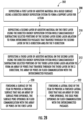
- An exemplary method 200 of forming a porous tool 112 may be performed using a porous-tool manufacturing system 100. As shown in FIG. 2A , an exemplary method 200 includes cooperatively or simultaneously operating an additive material source and an energy source so as to form a plurality of layers having a porous structure 300. The exemplary method 200 may include depositing an additive material on a build surface to form a film 204 while simultaneously subtracting selected portions of the additive material from the film to form a porous layer in the film 206.
- the exemplary method 200 may include depositing an additive material on a build surface to form a film 204 while followed by subtracting selected portions of the additive material from the film to form a porous layer in the film 206.
- the depositing of additive material may be performed using a directed energy deposition system and the subtracting selected portions of the additive material may be performed using laser ablation.
- the method 200 may be carried out in a processing chamber 102, such as a deposition chamber that provides a negative pressure environment, or an enclosure which may or may not provide a negative pressure environment.
- the porous tool 112 may be formed on a build platform 104 located within the processing chamber 102.
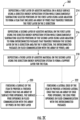
- FIGS. 2B and 2C show exemplary embodiments of forming a plurality of layers having a porous structure 300 according to the exemplary method 200 of forming a porous tool 112.
- forming a plurality of layers having a porous structure 300 may include depositing a first layer of additive material on the build surface using the directed energy deposition system to form a support layer for the film 208.
- a second layer of additive material may be deposited on the first layer using the directed energy deposition system while simultaneously subtracting selected portions of the second layer using laser ablation to form interconnected passages that traverse through the second layer in the x-direction and/or the y-direction 210.
- a third layer of additive material may be deposited on the second layer using the directed energy deposition system while simultaneously subtracting selected portions of the third layer using laser ablation to form an array of pores that traverse through the third layer in the z-direction, such that the array of pores are in fluid communication with the network of interconnected passages 212.
- a plurality of layers having a porous structure may be formed 202 according to an exemplary method 200 that includes depositing a first layer of additive material on the build surface using the directed energy deposition system while simultaneously subtracting selected portions of the first layer using laser ablation to form an array of pores that traverse through the first layer in the z-direction 214.
- a second layer of additive material may be deposited on the first layer using the directed energy deposition system while simultaneously subtracting selected portions of the second layer using laser ablation to form interconnected passages that traverse through the second layer in the x-direction and/or the y-direction, such that the interconnected passages in fluid communication with the array of pores 216.
- a third layer of additive material may be deposited on the second layer using the directed energy deposition system to form a support layer for the film 218.
- an exemplary method 200 may include finishing a surface of a film to provide a finished surface that has an array of surface pore openings, with the surface pore openings in fluid communication with the array of pores in the first layer 220. Additionally, or in the alternative, an exemplary method 200 may include finishing a lateral edge of the film to provide a finished lateral edge that has an array of edge pore openings, with the edge pore openings in fluid communication with the interconnected passages 222. A surface and/or a lateral edge may be finished using an energy source 108 in a subtractive process, a polishing tool, and/or any other suitable finishing tool.
- an exemplary method 200 may include separating the film from the build surface and attaching the film to a mold body, such that the porous tool includes the mold body with the film attached thereto. Additionally, or in the alternative, an exemplary method 200 may include depositing additional additive material on the film to form a mold body, for example, using the directed energy deposition system.
- the build surface may be formed by depositing additive material on a build platform using the directed energy deposition system. The build surface may define a support layer for the film.
- the plurality of layers may be formed at least in part by supplying an additive material from an additive material source and additively forming sequential layers of the additive material on a build platform.
- the one or more porous structures may be formed utilizing the energy source 108 in an additive process, such as reacting, sintering, melting, or curing the additive material.
- the energy source 108 may be utilized in such additive process when additively forming the sequential layers so as to form the porous structure at least in part via the additive process.
- the one or more porous structures may be formed utilizing the energy source 108 in a subtractive process, such as ablation, evaporation, sublimation, and/or micromachining the sequential layers of additive material.
- the one or more porous structures formed according to the exemplary method 200 may include a porous surface having an array of surface pore openings, and the array of surface pore openings may lead to an array of pores and/or a network of interconnected passages.
- the array of pores and/or network of interconnected passages may be configured to allow outgas to escape from one or more moldable materials, such as composite or additive manufacturing materials, during a composite fabrication and/or additive manufacturing process while the one or more moldable materials are conformed to the porous surface of the porous tool.
- the additive process includes a directed energy deposition (DED) system, such as a chemical vapor deposition (CVD) system, a laser engineered net shape (LENS) system, an electron beam additive melting (EBAM) system, or a rapid plasma deposition (RPD) system.
- DED directed energy deposition
- the exemplary method 200 includes additively forming sequential layers of an additive material using a directed energy deposition (DED) system, and cooperatively or simultaneously forming a porous structure in the sequential layers using the energy source in a subtractive process, such as laser ablation, evaporation, sublimation, or micromachining.
- a porous tool 112 may be formed according to an exemplary method 200 using any other porous-tool manufacturing system 100.
- the porous tool 112 formed according to the exemplary method 200 may embody a filter and/or a layup tool that has an integrally formed porous structure.
- FIGs. 3A-3I show a series of cross-sectional views of an exemplary porous tool 112.
- the cross-sectional views shown in FIGs. 3A-3I may correspond to steps in an exemplary method of forming the porous tool 112.
- Any porous-tool manufacturing system 100 may be used to form a porous tool 112 including the exemplary embodiments described herein.
- FIGs. 3A-3C show cross-sectional views of one embodiment of a porous tool 112, and/or a first layer of a porous tool 112. FIGs.
- 3D-3F show cross-sectional views of another embodiment of a porous tool 112, and/or a second layer of the porous tool 112.
- FIGs. 3G-3I show cross-sectional views of yet another embodiment of a porous tool 112, and/or a third layer of the porous tool 112.
- the respective cross-sectional views are shown with reference to a Cartesian coordinate system. It will be appreciated that the exemplary porous tool 112 shown in the respective cross-sections may be rotated about the Cartesian coordinate system without departing from the scope of the present disclosure.
- the porous tool 112 includes a porous structure 300.
- the porous structure may include one or more porous layers that have an array of pores, apertures, holes, slits, openings, passages, slots, or the like, or combinations thereof, which are sometimes collectively referred to herein as an array of pores 302.
- the porous structure 300 includes an additively-manufactured film. As shown in FIGs.
- a first porous layer 304 of a porous tool 112 such as an additively-manufactured film includes a porous surface 306 having an array of surface pore openings 308, with each one of the respective surface pore openings 308 leading to a corresponding pore 302 within the porous structure 300 of the film.
- the porous surface 306 may include one or more contours configured to conform a moldable material, such as a composite or additive manufacturing material, to a shape defined by the one or more contours.
- the one or more contours may be configured in any manner corresponding to the shape of a component to be formed using the porous tool 112.
- the porous structure 300 may be configured to allow outgas to escape from the one or more moldable materials during processes such as debulking, autoclaving, curing, pyrolysis, and/or other processes associated with molding, composite fabrication, and/or additive manufacturing.
- the array of pores 302 may be configured and arranged so as to traverse through the porous structure 300, such as through the first porous layer 304 of the porous structure 300, in any desired direction or directions, including in the z-direction as shown in FIGs. 3A-3C .
- a porous tool 112 may include a porous structure 300 that defines an array of surface pore openings 308 leading to an array of pores 302 that traverse the porous structure 300.
- a porous tool 112 may additionally or alternatively include a porous structure 300 such as an additively-manufactured film that has further layers in combination with the first porous layer 304 as described herein.
- a second porous layer 310 may be formed on top of or beneath the first porous layer 304 of the porous tool 112.
- the porous openings 308 may provide fluid communication with a network of interconnected passages 312 defined by the second porous layer 310 and/or the first porous layer 304.
- the network of interconnected passages 312 provide fluid communication with a plurality of edge pore openings 314.
- the edge pore openings 314 may be located along any one or more lateral edges of the film.
- the surface pore openings 308 are in fluid communication with the edge pore openings 314 by way of the array of pores 302 and the network of interconnected passages 312.
- the network of interconnected passages 312 may be configured and arranged so as to traverse through the porous structure 300, such as through the second porous layer 310 and/or the first porous layer 304 of the porous structure 300, in any desired direction or directions, including in the x- and/or y-direction as shown in FIGs. 3D-3E .
- a porous tool 112 may include a porous structure 300 that defines an array of surface pore openings 308 leading to an array of pores 302 which provide fluid communication to a network of interconnected passages 312 that traverse the porous structure 300 to an array of edge pore openings 314 located at one or more lateral edges of the porous structure 300.
- the array of pores may traverse the porous structure 300, such as a first porous layer 304 and/or a second porous layer 310 of the porous structure 300, in a first direction, such as a z-direction.
- the network of interconnected passages 312 may traverse the porous structure 300, such as the second layer 310 and/or a first layer 304, in a second direction, such as an x-direction, and/or a third direction, such as a y-direction.
- the array of pores 302 and the network of interconnected passages 312 provide a contiguous pathway from the surface pore openings 308 at the porous surface 306 of the porous tool 112 to the edge pore openings 314 at one or more lateral edges.
- Outgas may flow through such contiguous pathway such as during processes such as debulking, autoclaving, curing, pyrolysis, and/or other processes associated with molding, composite fabrication, and/or additive manufacturing.
- a porous tool 112 may include a third layer 316 which provides support to the porous structure 300.
- the third layer 316 may include a nonporous support layer.
- the third layer 316 may be formed on top of the second layer 310 of the porous tool 112.
- the third layer 316 may be substantially nonporous, in that the porous structure does not traverse the third layer 316.
- the third layer 316 may serve as a support layer for the porous tool 112.
- a porous tool 112 may include a porous structure 300 that includes an additively-manufactured film which has a porous layer (e.g., the first porous layer 304 and/or the second porous layer 310) and a nonporous layer (e.g., the third layer 316).
- the porous layer may include a porous surface 306 with an array of surface pore openings 308, a network of interconnected passages 312 in fluid communication with the surface pore openings 308, and one or more lateral edges that have an array of edge pore openings 314 in fluid communication with the network of interconnected passages 312.
- the porous tool may include an array of pores 302 that provide fluid communication between the surface pore openings 308 and the network of interconnected passages 312.
- the additively-manufactured film or porous structure 300 may include a substantially nonporous layer (e.g., the third layer 316) on one or more sides thereof.
- an exemplary porous tool 112 may include a porous structure 300 such as an additively-manufactured film and mold body 400.
- the porous structure 300 may be attached to the mold body 400 such as with a suitable adhesive, as shown in FIG. 4A .
- the porous structure 300 may be integrally formed as part of the mold body 400, or vice versa, as shown in FIG. 4B .
- the porous tool 112 may include a porous structure 300 such as a porous film with one or more porous layers 304, 310 as shown in FIGs. 3A-3C and/or 3D-3F, and a nonporous layer 316 as shown in FIGs. 3G-3I .
- the porous tool 112 may at least in part embody a layup tool that includes an integrally formed porous structure 300 as described herein.
- the layup tool may include an array of pores 302 and/or a network of interconnected passages 312, such as shown in FIGs. 3A-3C and/or 3D-3F.
- the layup tool may additionally include a substantially nonporous layer 316 such as shown in FIGs. 3G-3I .
- Exemplary porous tools 112 may be used as a filter and/or a layup tool in a molding process, such as a composite fabrication and/or additive manufacturing system, so as to allow outgas to escape from a moldable material (e.g., a composite or additive manufacturing material) during various processing steps such as debulking, autoclaving, curing, and/or pyrolysis.
- a moldable material e.g., a composite or additive manufacturing material
- the presently disclosed porous structures advantageously avoid pores that dead-end or otherwise fall short of their desired depth, thereby improving outgas evacuation as described herein.
- a porous-tool manufacturing system 100 may be configured to form a porous tool 112 that includes a porous structure 300 having any desired configuration and arrangement, as well as any desired geometry and size.
- the configuration, arrangement, geometry, and/or size of the pores 302 may be selected according to the desired porous properties of the porous tool 112.
- the desired properties of the porous tool 112 may be obtained by selectively forming the porous tool with an array of pores having a given configuration, arrangement, geometry, and or size.
- a porous tool 112 may be configured to provide a desired mass flux of outgas a given temperature and pressure.
- the porous layer (e.g., the first porous layer 304 and/or the second porous layer 310) may include pores 302 and/or a network of interconnected passages 312 configured and arranged in any desired pattern or combination of patterns, including patterns that embody an ordered array or a random or semi-random array.
- the surface pore openings 308, the pores 302, the interconnected passages 312, and/or the edge pore openings 314 may have any desired configuration, shape, and/or size.
- surface pore openings 308, pores 302, interconnected passages 312, and/or edge pore openings 314 may have a cross-sectional shape that includes one or more of the following profiles: circular, semi-circular, oval, ellipses, crescent, curvilinear, polygonal, irregular, random, semi-random, and/or combinations thereof.
- surface pore openings 308, pores 302, interconnected passages 312, and/or edge pore openings 314 may have an average cross-sectional width of 1 to 1,000 microns, such as 25 to 750 ⁇ m, such as 50 to 750 ⁇ m, such as 100 to 750 ⁇ m, such as 250 to 750 ⁇ m, such as 150 to 500 ⁇ m, such as 250 to 750 ⁇ m, such as 500 to 750 ⁇ m, such as 750 to 1,000 ⁇ m, such as 1 to 250 ⁇ m, such as 5 to 150 ⁇ m, such as 10 to 100 ⁇ m, such as 1 to 75 ⁇ m, such as 5 to 50 ⁇ m, such as 1 to 25 ⁇ m, or such as 5 to 25 ⁇ m.
- the surface pore openings 308, pores 302, interconnected passages 312, and/or edge pore openings 314 may have an average cross-sectional width of at least 1 micron, such as least 5 ⁇ m, such as least 10 ⁇ m, such as least 25 ⁇ m, such as least 50 ⁇ m, such as least 100 ⁇ m, such as least 150 ⁇ m, such as least 200 ⁇ m, such as least 250 ⁇ m, such as least 350 ⁇ m, such as least 500 ⁇ m, such as least 750 ⁇ m, or such as least 900 ⁇ m.
- the surface pore openings 308, pores 302, interconnected passages 312, and/or edge pore openings 314 may have an average cross-sectional width of at 1,000 micron or less, such as 900 ⁇ m or less, such as 750 ⁇ m or less, such as 500 ⁇ m or less, such as 350 ⁇ m or less, such as 250 ⁇ m or less, such as 200 ⁇ m or less, such as 150 ⁇ m or less, such as 100 ⁇ m or less, such as 50 ⁇ m or less, such as 25 ⁇ m or less, such as 10 ⁇ m or less, or such as 5 ⁇ m or less.
- a porous tool 112 may include a support layer such as the third layer 316 shown in FIGs. 3G-3I .
- the support layer may have any desired thickness, such as from 1 to 25 millimeters, such as from 1 to 10 mm, such as from 2.5 to 10 mm, such as from 2.5 to 5 mm, such as from 5 to 20 mm, such as from 10 to 25 mm, such as from 15 to 25 mm.
- the support layer may have a thickness of at least 1 millimeter, such as at least 2 mm, such as at least 6 mm, such as at least 12 mm, such as at least 16 mm, such as at least 22 mm.
- the support layer may have a thickness of less than 25 millimeters, such as less than 21 mm, such as less than 17 mm, such as less than 13 mm, such as less than 9 mm, such as less than 7 mm, such as less than 3 mm.
- a layup tool 500 may be used in a molding process, such as a composite fabrication and/or additive manufacturing process, to form a molded component, such as a composite or additively manufactured component.
- one or more moldable materials (e.g., composite or additive manufacturing materials) 502 may be conformed to a shape defined by a layup tool 500.
- the layup tool 500 includes a porous structure 300 as described herein.
- the layup tool 500 may include one or more mold bodies 400 such as one or more molds or mandrels.
- an exemplary layup tool 500 includes a first mold body504 and/or a second mold body 506.
- the first mold body 504 may include an external mold body 400
- the second mold body 506 may include an internal mold body 400.
- a mold body may include one or more outgas vents 508.
- the outgas vents 508 may align with one or more of the lateral edge pores 314 so as to provide a pathway for outgas to flow from the lateral edge pores 314 through the mold body 504, 506.
- Each of the one or more outgas vents 508 may align with one or more of the lateral edge pores 314.
- each lateral edge pore 314 need not have an individually corresponding outgas vent 508, but instead one outgas vent may provide a pathway for outgas to flow from a plurality of lateral edge pores.
- the outgas vents 508 may be regarded as an extension of the network of interconnected passages 312, for example, with each lateral edge pore 314 having a corresponding outgas vent 508.
- the outgas vents 508 may have a larger cross-sectional width relative to a corresponding lateral edge pore 314.
- outgas vents 508 may allow for easy alignment of the lateral edge pores with the outgas vents in embodiments where a porous structure 300 is adhered to a mold body 400 as shown in FIG. 4A . Additionally, or in the alternative, outgas vents 508 may allow for easier cleaning and/or minimize accumulation of contamination or deposited material from blocking the outgas vents.
- the outgas vents 508 may include a porous structure such as network of interconnected passages similar to that shown in FIGs. 3A-3I .
- one or more outgas vents 508 may be configured to interface with a process fitting, such as a fitting that supplies negative pressure to the porous structure. Such negative pressure may help evacuate outgas and/or conform the one or more moldable materials 502 to a shape defined by one or more contours of the porous surface 306 of the layup tool 500.
- a molded component such as a composite or additively manufactured component, may be formed from the one or more moldable materials 502 using a porous tool 112 that includes an external mold body 504 and/or an internal mold body 506.
- a porous tool 112 such as a layup tool 500
- the moldable materials 502 are conformed to a porous surface 308 of the porous tool 112.
- An external mold body 504 and an internal mold body 506 may be configured to be used together with one another as a system to form a molded component.
- an external mold body 504 or an internal mold body 506 may be configured to be used individually or separately from one another, such as in separate processes or separate steps of a process.
- a layup tool 500 may include an internal mold body 506 that becomes "trapped" within the molded component formed from the moldable materials 502.
- the internal mold body 506 may be removed using a mechanical and/or chemical process.
- the layup tool 500 e.g., the internal mold body 506
- the layup tool 500 may be formed from a ceramic material which may be leached out using a caustic or acidic solution, optionally under elevated temperature and/or pressure.
- the porous tool 112 may be used to form a molded component, such as a composite or additively manufactured component.
- a molded component such as a composite or additively manufactured component.
- one or more moldable materials 502 may be conformed to the shape of the layup tool 500, including an external mold body 504 and/or an internal mold body 506.
- a composite or additively manufactured component may be formed according to an exemplary method 600 shown in FIG. 6 .
- An exemplary method 600 includes conforming one or more moldable materials (e.g., composite or additive manufacturing materials) to a shape defined by a porous tool 602.
- the porous tool may include a mold body and an additively-manufactured film that has a porous layer and a nonporous support.
- the film may have been attached to a surface of the mold body 604, or the film may have been integrally formed as part of the mold body 606. Regardless of whether the film is attached to a surface of the mold body or integrally formed as part of the mold body, the exemplary method includes evacuating outgas from the one or more moldable materials through the porous layer of the film 608.
- the outgas may the porous layer through an array of surface pore openings located at a surface of the film in contact with the one or more moldable materials.
- the outgas may then traverse the porous layer through a network of interconnected passages, and exit the porous layer through an array of edge pore openings located at one or more lateral edges of the film.
- the porous tool may include a layup tool
- the exemplary method 600 may include forming an external surface using an external mold body 602 and/or forming an internal surface using an internal mold body 604, and evacuating outgas from the moldable materials through the porous structure of the layup tool 606.
- the exemplary method may include evacuating outgas through one or more outgas vents 508 in the porous tool.
- the exemplary method 600 may include removing an internal mold body that has become trapped within the composite or additively manufactured component, such as by way of leaching with a caustic or acidic solution, optionally under elevated temperature and/or pressure.
- the presently disclosed porous tools 112 may be used to form any molded component from any one or more moldable materials 502, including plastics, composites, and metal alloys, as well as combinations thereof.
- the moldable materials 502 may include ceramic matrix composite (CMC) materials.
- CMC materials include a ceramic matrix material and reinforcing fibers or cloth.
- Exemplary ceramic matrix materials include silicon carbide (SiC) and/or carbon (C).
- Exemplary CMC materials include carbon-fiber-reinforced carbon (C/C), carbon-fiber-reinforced silicon carbide (C/SiC), or silicon-carbide-reinforced silicon carbide (SiC/SiC).
- the moldable materials 502 may include polymer matrix composite (PMC) materials.
- PMC materials include a polymeric matrix material and reinforcing fibers or cloth.
- Exemplary PMC materials include fiber-reinforced plastics and advanced composites.
- Exemplary polymeric matrix materials include thermosets, such as epoxies, phenolics, polyurethanes, polyimides, bismaleimides, cyanate esters, phenolics, benzoxazines, phthalonitriles.
- polyimides may be particularly suitable.
- Exemplary polyimides include phenylethynyl-terminated imide (PETI) oligomers, biphenyl dianhydride-based 2,2'-dimethylbenzidine, ultrahigh-temperature HFPE.
- exemplary polyimides may include end caps, such as 4-phenylethynylphthalic anhydride (PEPA) and/or asymmetric oxydipththalic anhydride (a-ODPA) end caps.
- PEPA 4-phenylethynylphthalic anhydride
- a-ODPA asymmetric oxydipththalic anhydride
- Exemplary reinforcing fibers or cloth that may be utilized in CMC or PMC materials include carbon fibers, ceramic fibers, fiberglass, graphite fibers, and aramid fibers. Reinforcing fibers or cloth may be formed to the shape or contour of a layup tool 500, and then the fibers or cloth may be infiltrated with a matrix material. Exemplary reinforcing fibers include monofilaments, yarns, chopped whiskers or fibers, and/or particles.
- ceramic fibers may be formed of materials such a silicon carbide (SiC), carbon fiber (C), sapphire, alumina silicates, and/or oxides of Si, Al, Zr, Y, as well as combinations thereof.
- the reinforcing fibers may additionally include inorganic fillers, such as silica, quartz, pyrophyllite, wollastonite, mica, talc, kyanite, and/or montmorillonite, as well as combinations thereof.
- Moldable materials such as CMC or PMC materials may be applied to the porous tool 112 (e.g., a layup tool 500) using any molding, composite fabrication, and/or additive manufacturing process.
- Exemplary processes for forming a component from CMC or PMC materials include chemical vapor deposition (CVD), chemical vapor infiltration (CVI), polymer impregnation and pyrolysis (PIP), melt infiltration (MI), resin transfer molding (RTM), chemical reaction, sintering, or electrophoresis.
- the porous structure 300 of the porous tool 112 e.g., the layup tool 500
- any desired molded, composite, or additively manufactured component may be formed using any one or more of the presently disclosed porous tools.
- the presently disclosed porous tools may be configured to form any desired molded component, composite component, or additively manufactured component.
- Exemplary components include those used in turbomachines, including, turbojets, turbofans, turboprops, turboshafts, ramjets, rocket jets, pulse jets, turbines, gas turbines, steam turbines, marine engines, and the like.
- a porous tool may be configured to form a shroud component or a turbine blade for a turbomachine such as a turbofan engine commonly used in aircraft, including commercial, military, and civilian aircraft.
- the component may include a ceramic matrix composite (CMC) material, a polymeric matrix composite (PMC) material, and/or a superalloy.
- CMC ceramic matrix composite
- PMC polymeric matrix composite
- superalloy a superalloy
Landscapes
- Engineering & Computer Science (AREA)
- Mechanical Engineering (AREA)
- Chemical & Material Sciences (AREA)
- Physics & Mathematics (AREA)
- Manufacturing & Machinery (AREA)
- Materials Engineering (AREA)
- Plasma & Fusion (AREA)
- Optics & Photonics (AREA)
- Organic Chemistry (AREA)
- Chemical Kinetics & Catalysis (AREA)
- Metallurgy (AREA)
- General Chemical & Material Sciences (AREA)
- Laser Beam Processing (AREA)
- Powder Metallurgy (AREA)
- Producing Shaped Articles From Materials (AREA)
- Chemical Vapour Deposition (AREA)
- Moulds For Moulding Plastics Or The Like (AREA)
Claims (9)
- Verfahren zum Ausbilden eines porösen Werkzeugs (118), wobei das poröse Werkzeug (118) eine x-Richtung, eine y-Richtung und eine z-Richtung definiert, das poröse Werkzeug (118) umfassend einen Formkörper, eine nicht-poröse Trägerstruktur auf dem Formkörper und eine poröse Struktur auf der nicht-porösen Trägerstruktur, das Verfahren umfassend:Abscheiden (208) einer ersten Schicht aus Zusatzmaterial (116) auf einer Bauoberfläche unter Verwendung eines Systems (100) einer gerichteten Energieabscheidung, um eine Trägerschicht (316) auszubilden, wobei die erste Schicht aus Zusatzmaterial (116) die nicht-poröse Trägerstruktur definiert;Abscheiden (210) einer zweiten Schicht (310) aus Zusatzmaterial (116) auf der ersten Schicht aus Zusatzmaterial (116) unter Verwendung des Systems (100) der gerichteten Energieabscheidung, während gleichzeitig ausgewählte Abschnitte der zweiten Schicht (310) unter Verwendung einer Laserablation abgetragen werden, um miteinander verbundene Durchgänge (312) auszubilden, die die zweite Schicht (310) in der x-Richtung und/oder der y-Richtung durchqueren;Abscheiden (212) einer dritten Schicht aus Zusatzmaterial (116) auf der zweiten Schicht (310) unter Verwendung des Systems (100) der gerichteten Energieabscheidung, während gleichzeitig ausgewählte Abschnitte der dritten Schicht aus Zusatzmaterial (116) unter Verwendung der Laserablation abgetragen werden, um eine Anordnung von Poren (302) auszubilden, die die dritte Schicht aus Zusatzmaterial (116) in der z-Richtung durchquert, wobei die Anordnung von Poren (302) in Fluidkommunikation mit den miteinander verbundenen Durchgängen (312) steht, wobei die zweite Schicht (310) aus Zusatzmaterial (116) und die dritte Schicht aus Zusatzmaterial (116) die poröse Struktur definieren;Fertigstellen (222) eines Seitenrands der porösen Struktur, um einen fertiggestellten Seitenrand bereitzustellen, umfassend eine Anordnung von Randporenöffnungen (314), wobei die Anordnung von Randporenöffnungen (314) in Fluidkommunikation mit den miteinander verbundenen Durchgängen (312) steht;Fertigstellen (220) einer Oberfläche (306) der porösen Struktur, um eine fertiggestellte Oberfläche (306) bereitzustellen, umfassend eine Anordnung von Oberflächenporenöffnungen (308), wobei die Anordnung von Oberflächenporenöffnungen (308) in Fluidkommunikation mit der Anordnung von Poren (302) in der dritten Schicht aus Zusatzmaterial (116) steht; wobeieine oder mehrere der Randporenöffnungen der Anordnung von Randporenöffnungen (314) an eine oder mehrere Ausgasöffnungen ausgerichtet sind, die in dem Formkörper positioniert sind; und(a) Trennen der nicht-porösen Trägerstruktur von der Bauoberfläche und Befestigen der nicht-porösen Trägerstruktur an dem Formkörper; oder(b) Abscheiden von zusätzlichem Zusatzmaterial (116) auf der porösen Struktur, um den Formkörper unter Verwendung des Systems (100) der gerichteten Energieabscheidung auszubilden.
- Verfahren zum Ausbilden eines porösen Werkzeugs (118), wobei das poröse Werkzeug (118) eine x-Richtung, eine y-Richtung und eine z-Richtung definiert, das poröse Werkzeug (118) umfassend einen Formkörper, eine nicht-poröse Trägerstruktur auf dem Formkörper und eine poröse Struktur auf der nicht-porösen Trägerstruktur, das Verfahren umfassend:Abscheiden (214) einer ersten Schicht (304) aus Zusatzmaterial (116) auf einer Bauoberfläche unter Verwendung eines Systems (100) der gerichteten Energieabscheidung, während gleichzeitig ausgewählte Abschnitte der ersten Schicht (304) unter Verwendung der Laserablation abgetragen werden, um eine Anordnung von Poren (302) auszubilden, die die erste Schicht (304) in der z-Richtung durchquert;Abscheiden (216) einer zweiten Schicht (310) aus Zusatzmaterial (116) auf der ersten Schicht (304) unter Verwendung des Systems (100) der gerichteten Energieabscheidung, während gleichzeitig ausgewählte Abschnitte der zweiten Schicht (310) unter Verwendung der Laserablation abgetragen werden, um miteinander verbundene Durchgänge (312) auszubilden, die die zweite Schicht (310) in der x-Richtung und/oder der y-Richtung durchqueren, wobei die miteinander verbundenen Durchgänge (312) in Fluidkommunikation mit der Anordnung von Poren (302) stehen, wobei die erste Schicht (304) aus Zusatzmaterial (116) und die zweite Schicht (310) aus Zusatzmaterial (116) die poröse Struktur definieren;Abscheiden (218) einer dritten Schicht aus Zusatzmaterial (116) auf der zweiten Schicht (310) unter Verwendung des Systems (100) der gerichteten Energieabscheidung, um eine Trägerschicht (316) für die poröse Struktur auszubilden, wobei die dritte Schicht aus Zusatzmaterial (116) die nicht-poröse Trägerstruktur definiert;Fertigstellen (222) eines Seitenrands der porösen Struktur, um einen fertiggestellten Seitenrand bereitzustellen, umfassend eine Anordnung von Randporenöffnungen (304), wobei die Anordnung von Randporenöffnungen (314) in Fluidkommunikation mit den miteinander verbundenen Durchgängen (312) steht; undFertigstellen (220) einer Oberfläche (306) der porösen Struktur, um eine fertiggestellte Oberfläche (306) bereitzustellen, umfassend eine Anordnung von Oberflächenporenöffnungen (308), wobei die Anordnung von Oberflächenporenöffnungen (308) in Fluidkommunikation mit der Anordnung von Poren (302) in der ersten Schicht (304) steht; wobeieine oder mehrere der Randporenöffnungen der Anordnung von Randporenöffnungen (314) an eine oder mehrere Ausgasöffnungen ausgerichtet sind, die in dem Formkörper positioniert sind; und
(a) ferner umfassend das Trennen der porösen Struktur von der Bauoberfläche und das Befestigen der porösen Struktur an dem Formkörper; oder (b) wobei der Formkörper durch Abscheiden von zusätzlichem Zusatzmaterial (116) auf der porösen Struktur unter Verwendung des Systems der gerichteten Energieabscheidung ausgebildet wird, wodurch der Formkörper, die nicht-poröse Trägerstruktur und die poröse Struktur integral ausgebildet werden. - Verfahren nach Anspruch 1 oder 2, ferner umfassend:
Ausbilden der porösen Struktur, um eine oder mehrere Konturen einzuschließen, die konfiguriert sind, um ein formbares Material an eine Form anzupassen, die durch die eine oder die mehreren Konturen definiert ist. - Poröses Werkzeug (118), wobei das poröse Werkzeug (118) eine x-Richtung, eine y-Richtung und eine z-Richtung definiert, das poröse Werkzeug (118) umfassend einen Formkörper, eine nicht-poröse Trägerstruktur auf dem Formkörper und eine poröse Struktur auf der nicht-porösen Trägerstruktur, das poröse Werkzeug umfassend:eine erste Schicht, die die nichtporöse Trägerstruktur definiert;eine zweite Schicht (310), die mit der ersten Schicht integral ist, die miteinander verbundene Durchgänge (312) aufweist, die die zweite Schicht (310) in der x-Richtung und/oder der y-Richtung durchquert;eine dritte Schicht, die mit der zweiten Schicht (310) integral ist und eine Anordnung von Poren (302) aufweist, die die dritte Schicht in der z-Richtung durchquert, wobei die Anordnung von Poren (302) in Fluidkommunikation mit den miteinander verbundenen Durchgängen (312) steht, wobei die zweite Materialschicht und die dritte Materialschicht die poröse Struktur definieren;einen Seitenrand der porösen Struktur, die ein fertiggestellter Seitenrand ist, umfassend eine Anordnung von Randporenöffnungen (314), wobei die Anordnung von Randporenöffnungen (314) in Fluidkommunikation mit den miteinander verbundenen Durchgängen (312) steht;eine Oberfläche (306) der porösen Struktur, die eine fertiggestellte Oberfläche (306) ist, umfassend eine Anordnung von Oberflächenporenöffnungen (308), wobei die Anordnung von Oberflächenporenöffnungen (308) in Fluidkommunikation mit der Anordnung von Poren (302) in der dritten Schicht steht; wobeieine oder mehrere der Randporenöffnungen der Anordnung von Randporenöffnungen (314) an eine oder mehrere Ausgasöffnungen ausgerichtet sind, die in dem Formkörper positioniert sind; unda) die nicht-poröse Trägerstruktur an dem Formkörper befestigt ist; oderb) die poröse Struktur an dem Formkörper befestigt ist; oderc) der Formkörper, die nicht-poröse Trägerstruktur und die poröse Struktur integral ausgebildet sind.
- Poröses Werkzeug (118) nach Anspruch 4, wobei die poröse Struktur eine Dicke von 100 bis 1.000 Mikrometer und die nicht-poröse Trägerstruktur eine Dicke von 1 bis 10 Millimeter aufweist.
- Poröses Werkzeug (118) nach Anspruch 4 oder 5, wobei jede der Poren der Anordnung von Poren (302) und/oder jeder der miteinander verbundenen Durchgänge (312) eine durchschnittliche Querschnittsbreite von 1 bis 25 Mikrometer aufweist.
- Poröses Werkzeug (118) nach einem der Ansprüche 4 bis 6, wobei die poröse Struktur entweder an den Formkörper (400) geklebt oder mit dem Formkörper (400) integral ausgebildet ist.
- Verfahren zum Ausbilden einer geformten Komponente, das Verfahren umfassend: Anpassen eines oder mehrerer formbarer Materialien (502) einer Form unter Verwendung eines porösen Werkzeugs (118), wobei das poröse Werkzeug (118) einem der Ansprüche 4 bis 7 entspricht; und Absaugen von Ausgasen aus dem einen oder den mehreren formbaren Materialien (502) durch die poröse Schicht (304), (310) der porösen Struktur hindurch, wobei die Ausgase in die poröse Schicht (304), (310) durch die Anordnung von Oberflächenporenöffnungen (308) hindurch eintreten, die sich an der Oberfläche (306) der porösen Struktur in Kontakt mit dem einen oder den mehreren formbaren Materialien (502) befinden, die die poröse Schicht (304), (310) durch die miteinander verbundenen Durchgänge (312) durchqueren und die poröse Schicht (304), (310) durch die Anordnung von Randporenöffnungen (314) hindurch verlassen, die sich an einem oder mehreren Seitenrändern der porösen Struktur befinden.
- Verfahren nach Anspruch 8, umfassend:
Anpassen des einen oder der mehreren formbaren Materialien (502) in die Form einer Deckbandkomponente für eine Turbomaschine oder in die Form einer Turbinenschaufelkomponente für die Turbomaschine, das eine oder die mehreren formbaren Materialien (502) umfassend ein Keramikmatrix-Verbundwerkstoff-Material (CMC-Material), ein Polymermatrix-Verbundwerkstoff-Material (PMC-Material) und/oder eine Superlegierung.
Priority Applications (1)
| Application Number | Priority Date | Filing Date | Title |
|---|---|---|---|
| EP24196835.3A EP4446045A3 (de) | 2018-08-22 | 2019-08-19 | Poröse werkzeuge und verfahren zur herstellung davon |
Applications Claiming Priority (1)
| Application Number | Priority Date | Filing Date | Title |
|---|---|---|---|
| US16/108,657 US10780498B2 (en) | 2018-08-22 | 2018-08-22 | Porous tools and methods of making the same |
Related Child Applications (2)
| Application Number | Title | Priority Date | Filing Date |
|---|---|---|---|
| EP24196835.3A Division EP4446045A3 (de) | 2018-08-22 | 2019-08-19 | Poröse werkzeuge und verfahren zur herstellung davon |
| EP24196835.3A Division-Into EP4446045A3 (de) | 2018-08-22 | 2019-08-19 | Poröse werkzeuge und verfahren zur herstellung davon |
Publications (2)
| Publication Number | Publication Date |
|---|---|
| EP3620253A1 EP3620253A1 (de) | 2020-03-11 |
| EP3620253B1 true EP3620253B1 (de) | 2024-10-09 |
Family
ID=67659315
Family Applications (2)
| Application Number | Title | Priority Date | Filing Date |
|---|---|---|---|
| EP24196835.3A Pending EP4446045A3 (de) | 2018-08-22 | 2019-08-19 | Poröse werkzeuge und verfahren zur herstellung davon |
| EP19192360.6A Active EP3620253B1 (de) | 2018-08-22 | 2019-08-19 | Poröse werkzeuge und verfahren zur herstellung davon |
Family Applications Before (1)
| Application Number | Title | Priority Date | Filing Date |
|---|---|---|---|
| EP24196835.3A Pending EP4446045A3 (de) | 2018-08-22 | 2019-08-19 | Poröse werkzeuge und verfahren zur herstellung davon |
Country Status (5)
| Country | Link |
|---|---|
| US (1) | US10780498B2 (de) |
| EP (2) | EP4446045A3 (de) |
| JP (2) | JP6903720B2 (de) |
| CN (2) | CN115635095A (de) |
| CA (1) | CA3051961C (de) |
Families Citing this family (8)
| Publication number | Priority date | Publication date | Assignee | Title |
|---|---|---|---|---|
| HUE048430T2 (hu) * | 2014-12-22 | 2020-07-28 | Celwise Ab | Egy termék formázási metódusa, amely cellulóz szuszpenzió felhasználásával és az ilyen eljárásban használt szerszám vagy szerszámrész segítségével történik |
| JP7720735B2 (ja) * | 2020-08-28 | 2025-08-08 | 東京エレクトロン株式会社 | プラズマ環境下で使用される消耗部品のコーティング用シリコン成膜装置、コーティング用シリコンを含む膜を有するプラズマ環境下で使用される消耗部品の製造方法、及びシリコン成膜装置 |
| US11571863B2 (en) | 2021-05-24 | 2023-02-07 | Spirit Aerosystems, Inc. | Methods of fabricating multi-region U-shaped composite structures |
| US12049040B2 (en) * | 2021-07-28 | 2024-07-30 | Khalifa University of Science and Technology | 3D printing on membrane of filtration device |
| CN115366229B (zh) * | 2021-08-16 | 2024-08-06 | 三峡大学 | 采用蜂窝煤炉胆坯体高效成形装置进行炉胆坯体成型的方法 |
| US12330374B2 (en) * | 2021-09-08 | 2025-06-17 | International Business Machines Corporation | Performing corrective actions during three-dimensional printing jobs |
| US12392037B2 (en) | 2022-10-21 | 2025-08-19 | Rtx Corporation | Floating tooling assembly for chemical vapor infiltration |
| CN117140846A (zh) * | 2023-10-13 | 2023-12-01 | 华中科技大学鄂州工业技术研究院 | 透气金属模具及其制备方法 |
Citations (2)
| Publication number | Priority date | Publication date | Assignee | Title |
|---|---|---|---|---|
| EP0713248A2 (de) * | 1994-11-17 | 1996-05-22 | Hitachi, Ltd. | Giessverfahren und Vorrichtung dafür |
| US20070007699A1 (en) * | 2003-09-11 | 2007-01-11 | Extrude Hone Corporation | Layered manufactured articles having small-width fluid conduction vents and methods of making same |
Family Cites Families (86)
| Publication number | Priority date | Publication date | Assignee | Title |
|---|---|---|---|---|
| GB636818A (en) | 1948-05-05 | 1950-05-10 | George Oulianoff | Improvements relating to gas-turbine engine parts |
| JPS5216137B2 (de) * | 1972-11-17 | 1977-05-07 | ||
| US4047873A (en) | 1975-12-15 | 1977-09-13 | Consupak, Inc. | Apparatus for making multilayered blow molded articles |
| US4208177A (en) | 1977-12-14 | 1980-06-17 | Logic Devices, Inc. | Fluid cooling of injection molded plastic articles |
| US5147587A (en) * | 1986-10-17 | 1992-09-15 | Board Of Regents, The University Of Texas System | Method of producing parts and molds using composite ceramic powders |
| US4863538A (en) * | 1986-10-17 | 1989-09-05 | Board Of Regents, The University Of Texas System | Method and apparatus for producing parts by selective sintering |
| US5076869A (en) * | 1986-10-17 | 1991-12-31 | Board Of Regents, The University Of Texas System | Multiple material systems for selective beam sintering |
| US4783341A (en) | 1987-05-04 | 1988-11-08 | United Technologies Corporation | Method and apparatus for measuring the density and hardness of porous plasma sprayed coatings |
| US5031483A (en) * | 1989-10-06 | 1991-07-16 | W. R. Weaver Co. | Process for the manufacture of laminated tooling |
| US5169678A (en) * | 1989-12-26 | 1992-12-08 | General Electric Company | Laser ablatable polymer dielectrics and methods |
| US5286573A (en) * | 1990-12-03 | 1994-02-15 | Fritz Prinz | Method and support structures for creation of objects by layer deposition |
| US5207371A (en) * | 1991-07-29 | 1993-05-04 | Prinz Fritz B | Method and apparatus for fabrication of three-dimensional metal articles by weld deposition |
| US5775402A (en) * | 1995-10-31 | 1998-07-07 | Massachusetts Institute Of Technology | Enhancement of thermal properties of tooling made by solid free form fabrication techniques |
| US5411772A (en) | 1994-01-25 | 1995-05-02 | Rockwell International Corporation | Method of laser ablation for uniform thin film deposition |
| US5449427A (en) * | 1994-05-23 | 1995-09-12 | General Electric Company | Processing low dielectric constant materials for high speed electronics |
| US5508065A (en) * | 1994-10-14 | 1996-04-16 | Regents Of The University Of California | Method for materials deposition by ablation transfer processing |
| US5858876A (en) | 1996-04-01 | 1999-01-12 | Chartered Semiconductor Manufacturing, Ltd. | Simultaneous deposit and etch method for forming a void-free and gap-filling insulator layer upon a patterned substrate layer |
| US5850590A (en) | 1996-04-19 | 1998-12-15 | Kabushiki Kaisha Kobe Seiko Sho | Method for making a porous sintered material |
| JP3525718B2 (ja) * | 1998-01-30 | 2004-05-10 | 松下電工株式会社 | 注型型及び注型方法 |
| US6136725A (en) | 1998-04-14 | 2000-10-24 | Cvd Systems, Inc. | Method for chemical vapor deposition of a material on a substrate |
| US6399177B1 (en) | 1999-06-03 | 2002-06-04 | The Penn State Research Foundation | Deposited thin film void-column network materials |
| US6210986B1 (en) | 1999-09-23 | 2001-04-03 | Sandia Corporation | Microfluidic channel fabrication method |
| US20010048988A1 (en) | 1999-09-28 | 2001-12-06 | Glenn J. Forte | Polyolefin bottles and method for making same |
| US6359367B1 (en) | 1999-12-06 | 2002-03-19 | Acuson Corporation | Micromachined ultrasonic spiral arrays for medical diagnostic imaging |
| DE10053742C5 (de) * | 2000-10-30 | 2006-06-08 | Concept Laser Gmbh | Vorrichtung zum Sintern, Abtragen und/oder Beschriften mittels elektromagnetischer gebündelter Strahlung sowie Verfahren zum Betrieb der Vorrichtung |
| US6835426B2 (en) * | 2001-01-19 | 2004-12-28 | Potomac Photonics, Inc. | Method and apparatus for pulse-position synchronization in miniature structures manufacturing processes |
| JP3446748B2 (ja) * | 2001-04-24 | 2003-09-16 | 松下電工株式会社 | 三次元形状造形物の製造方法および成形金型 |
| US7785098B1 (en) | 2001-06-05 | 2010-08-31 | Mikro Systems, Inc. | Systems for large area micro mechanical systems |
| CA2448736C (en) | 2001-06-05 | 2010-08-10 | Mikro Systems, Inc. | Methods for manufacturing three-dimensional devices and devices created thereby |
| US7141812B2 (en) | 2002-06-05 | 2006-11-28 | Mikro Systems, Inc. | Devices, methods, and systems involving castings |
| US6619369B2 (en) | 2001-08-08 | 2003-09-16 | Try Co., Ltd. | Process for producing a thin die-cast molded article of an aluminum material |
| US6737007B2 (en) | 2002-09-19 | 2004-05-18 | Husky Injection Molding Systems, Ltd | Cooling tube with porous insert |
| US6864190B2 (en) * | 2002-10-17 | 2005-03-08 | National Research Council Of Canada | Laser chemical fabrication of nanostructures |
| EP1557250B1 (de) * | 2002-11-01 | 2013-02-13 | Kabushiki Kaisha Bridgestone | Verfahren zur herstellung einer reifenvulkanisierform |
| EP1418013B1 (de) * | 2002-11-08 | 2005-01-19 | Howmedica Osteonics Corp. | Lasererzeugte poröse Oberfläche |
| US6865140B2 (en) | 2003-03-06 | 2005-03-08 | General Electric Company | Mosaic arrays using micromachined ultrasound transducers |
| US20060000709A1 (en) * | 2004-06-30 | 2006-01-05 | Sebastian Bohm | Methods for modulation of flow in a flow pathway |
| ATE464025T1 (de) * | 2004-08-13 | 2010-04-15 | Setagon Inc | Herstellungsverfahren für medizinprodukte mit nanoporösen schichten |
| US7473086B2 (en) | 2004-12-01 | 2009-01-06 | General Electric Company | Porous mold insert and molds |
| US7332425B2 (en) | 2005-05-11 | 2008-02-19 | Texas Instruments Incorporated | Simultaneous deposition and etch process for barrier layer formation in microelectronic device interconnects |
| CN101257871A (zh) * | 2005-07-19 | 2008-09-03 | 麦克内尔-Ppc股份有限公司 | 三维多孔膜 |
| US20070141375A1 (en) * | 2005-12-20 | 2007-06-21 | Budinger David E | Braze cladding for direct metal laser sintered materials |
| JP5575374B2 (ja) | 2008-03-26 | 2014-08-20 | パナソニック株式会社 | 樹脂射出成形用金型 |
| JP5250338B2 (ja) * | 2008-08-22 | 2013-07-31 | パナソニック株式会社 | 三次元形状造形物の製造方法、その製造装置および三次元形状造形物 |
| US9315663B2 (en) | 2008-09-26 | 2016-04-19 | Mikro Systems, Inc. | Systems, devices, and/or methods for manufacturing castings |
| DE102009016110B4 (de) | 2009-04-03 | 2015-03-05 | Tutech Innovation Gmbh | Verwendung einer Gießform zum Spritzgießen eines Kunststoffgussteils |
| EP2486446B1 (de) * | 2009-10-05 | 2016-11-30 | Acreo Swedish ICT AB | Elektrochrome Aktivmatrix-Anzeigevorrichtung und Herstellungsverfahren dafür |
| US20110132562A1 (en) | 2009-12-08 | 2011-06-09 | Merrill Gary B | Waxless precision casting process |
| KR20140016321A (ko) | 2011-03-11 | 2014-02-07 | 신토고교 가부시키가이샤 | 다이캐스트 금형 |
| US8932518B2 (en) | 2012-02-29 | 2015-01-13 | General Electric Company | Mold and facecoat compositions |
| US20140010951A1 (en) | 2012-06-26 | 2014-01-09 | Zimmer, Inc. | Porous metal implants made from custom manufactured substrates |
| US9776282B2 (en) * | 2012-10-08 | 2017-10-03 | Siemens Energy, Inc. | Laser additive manufacture of three-dimensional components containing multiple materials formed as integrated systems |
| US9550349B1 (en) | 2012-10-31 | 2017-01-24 | The Boeing Company | System and method for additive fabrication using laminated sheets |
| US20140126995A1 (en) | 2012-11-06 | 2014-05-08 | General Electric Company | Microchannel cooled turbine component and method of forming a microchannel cooled turbine component |
| CN105008073A (zh) * | 2013-03-05 | 2015-10-28 | 联合工艺公司 | 建立用于增材制造的平台 |
| US20160032766A1 (en) | 2013-03-14 | 2016-02-04 | General Electric Company | Components with micro cooled laser deposited material layer and methods of manufacture |
| CN105102099B (zh) | 2013-03-15 | 2018-10-19 | 派罗特克公司 | 陶瓷过滤器 |
| US20160023375A1 (en) * | 2013-05-17 | 2016-01-28 | Core Cast, Llc | Slip mixture for 3d printed molds and 3d printing ceramic material |
| WO2015081996A1 (en) * | 2013-12-04 | 2015-06-11 | European Space Agency | Manufacturing of a ceramic article from a metal preform or metal matrix composite preform provided by 3d-printing or 3d-weaving |
| GB201322838D0 (en) | 2013-12-23 | 2014-02-12 | Rolls Royce Plc | A combustion chamber |
| SE537836C2 (sv) * | 2014-02-06 | 2015-11-03 | Exeger Sweden Ab | En transparent färgämnessensibiliserad solcell samt ett sättför framställning av densamma |
| GB201403404D0 (en) | 2014-02-27 | 2014-04-16 | Rolls Royce Plc | A combustion chamber wall and a method of manufacturing a combustion chamber wall |
| GB201405988D0 (en) * | 2014-04-03 | 2014-05-21 | Rolls Royce Plc | Bonding method |
| US10377060B2 (en) * | 2014-05-27 | 2019-08-13 | Bridgestone Corporation | Mold, tire curing mold, and method for manufacturing mold |
| TWI614113B (zh) * | 2014-09-30 | 2018-02-11 | Panasonic Intellectual Property Management Co., Ltd. | 射出成型用模具與濾網成型品 |
| EP3002517A1 (de) | 2014-09-30 | 2016-04-06 | Siemens Aktiengesellschaft | Poröse rotierende Maschinenkomponente, Brennkammer und Herstellungsverfahren |
| US9937652B2 (en) | 2015-03-04 | 2018-04-10 | Berry Plastics Corporation | Polymeric material for container |
| DE102015206892A1 (de) * | 2015-04-16 | 2016-10-20 | Siemens Aktiengesellschaft | Verfahren zum Herstellen eines Bauteils durch thermisches Spritzen und Anlage zum Herstellen eines Bauteils mit einer Vorrichtung zum thermischen Spritzen |
| US20160318129A1 (en) * | 2015-05-01 | 2016-11-03 | General Electric Company | System and method for multi-laser additive manufacturing |
| JP5940712B1 (ja) * | 2015-05-25 | 2016-06-29 | Dmg森精機株式会社 | 加工機械 |
| JP6512407B2 (ja) * | 2015-07-31 | 2019-05-15 | パナソニックIpマネジメント株式会社 | 三次元形状造形物の製造方法 |
| JP6471975B2 (ja) * | 2015-07-31 | 2019-02-20 | パナソニックIpマネジメント株式会社 | 三次元形状造形物の製造方法および三次元形状造形物 |
| JP6628024B2 (ja) * | 2015-07-31 | 2020-01-08 | パナソニックIpマネジメント株式会社 | 三次元形状造形物の製造方法および三次元形状造形物 |
| JP2018530501A (ja) | 2015-08-13 | 2018-10-18 | コーニング インコーポレイテッド | 積層造形プロセスおよび製品 |
| FR3041890B1 (fr) * | 2015-10-05 | 2017-11-24 | Snecma | Procede de fabrication d'une piece en materiau composite par injection d'une barbotine chargee dans un moule poreux |
| WO2017087204A1 (en) * | 2015-11-18 | 2017-05-26 | Corning Incorporated | Powder, process of making the powder, and articles made therefrom |
| WO2017092764A1 (en) * | 2015-11-30 | 2017-06-08 | Vestas Wind Systems A/S | Method of manufacturing a wind turbine blade and wind turbine blade |
| US10226812B2 (en) * | 2015-12-21 | 2019-03-12 | United Technologies Corporation | Additively manufactured core for use in casting an internal cooling circuit of a gas turbine engine component |
| JP6643631B2 (ja) * | 2016-03-09 | 2020-02-12 | パナソニックIpマネジメント株式会社 | 三次元形状造形物の製造方法 |
| US10959850B2 (en) * | 2016-06-01 | 2021-03-30 | Corentec Co., Ltd. | Implant having porous layer and molding method thereof |
| JP7065351B2 (ja) * | 2016-09-02 | 2022-05-12 | パナソニックIpマネジメント株式会社 | 三次元形状造形物の製造方法 |
| CN106624369A (zh) * | 2016-10-14 | 2017-05-10 | 清华大学 | 一种快速制备氧化物多级纳米结构的方法 |
| US20180161856A1 (en) | 2016-12-13 | 2018-06-14 | General Electric Company | Integrated casting core-shell structure and filter for making cast component |
| CN106513996B (zh) | 2016-12-30 | 2019-02-15 | 中国科学院宁波材料技术与工程研究所 | 全激光复合增材制造方法和装置 |
| US20180369961A1 (en) * | 2017-06-23 | 2018-12-27 | Applied Materials, Inc. | Treatment of solidified layer |
| US11001002B2 (en) * | 2017-08-24 | 2021-05-11 | The Regents Of The University Of California | Powder bed additive manufacturing method of fabricating a porous matrix |
-
2018
- 2018-08-22 US US16/108,657 patent/US10780498B2/en active Active
-
2019
- 2019-08-07 JP JP2019145532A patent/JP6903720B2/ja active Active
- 2019-08-14 CA CA3051961A patent/CA3051961C/en active Active
- 2019-08-19 EP EP24196835.3A patent/EP4446045A3/de active Pending
- 2019-08-19 EP EP19192360.6A patent/EP3620253B1/de active Active
- 2019-08-22 CN CN202211278571.2A patent/CN115635095A/zh active Pending
- 2019-08-22 CN CN201910779254.0A patent/CN110856888B/zh active Active
-
2021
- 2021-06-22 JP JP2021103134A patent/JP7091527B2/ja active Active
Patent Citations (2)
| Publication number | Priority date | Publication date | Assignee | Title |
|---|---|---|---|---|
| EP0713248A2 (de) * | 1994-11-17 | 1996-05-22 | Hitachi, Ltd. | Giessverfahren und Vorrichtung dafür |
| US20070007699A1 (en) * | 2003-09-11 | 2007-01-11 | Extrude Hone Corporation | Layered manufactured articles having small-width fluid conduction vents and methods of making same |
Also Published As
| Publication number | Publication date |
|---|---|
| CN110856888B (zh) | 2022-11-08 |
| JP7091527B2 (ja) | 2022-06-27 |
| EP4446045A2 (de) | 2024-10-16 |
| CN115635095A (zh) | 2023-01-24 |
| CN110856888A (zh) | 2020-03-03 |
| JP2021178363A (ja) | 2021-11-18 |
| CA3051961A1 (en) | 2020-02-22 |
| US10780498B2 (en) | 2020-09-22 |
| EP4446045A3 (de) | 2025-06-04 |
| JP6903720B2 (ja) | 2021-07-14 |
| JP2020032463A (ja) | 2020-03-05 |
| EP3620253A1 (de) | 2020-03-11 |
| CA3051961C (en) | 2021-12-07 |
| US20200061709A1 (en) | 2020-02-27 |
Similar Documents
| Publication | Publication Date | Title |
|---|---|---|
| EP3620253B1 (de) | Poröse werkzeuge und verfahren zur herstellung davon | |
| JP7071009B2 (ja) | 犠牲繊維および非湿潤塗膜を使用してセラミック基質複合材料を形成する方法 | |
| EP2650478B1 (de) | Keramische Matrixverbundstoffvorform mit Hohlraum und Verfahren zu deren Herstellung | |
| EP3401506B1 (de) | Verfahren zur formung von mikrokanälen in cmc-komponenten | |
| JP6888933B2 (ja) | セラミックマトリックス複合材構成部品及びセラミックマトリックス複合材構成部品の製造方法 | |
| JP6247815B2 (ja) | セラミックマトリックス複合材の形成方法及びセラミックマトリックス複合材部品 | |
| US20160214283A1 (en) | Composite tool and method for forming composite components | |
| EP3184213B1 (de) | Verfahren zur generativen fertigung zur herstellung von überhängenden laschen in kühllöchern | |
| CN107034444B (zh) | 陶瓷基质复合物构件和制造陶瓷基质复合物构件的工艺 | |
| CN106393388A (zh) | 层片、制造层片的方法以及利用层片制造制品的方法 | |
| EP2762311B1 (de) | Herstellungsverfahren einer Formstruktur mit einem gewünschten porösen Anteil | |
| JP2021098646A (ja) | セラミックマトリックス複合材料コンポーネントおよびセラミックマトリックス複合材料コンポーネントを生産する方法 | |
| CN110382444A (zh) | 用于生产固结的纤维预制件的方法 | |
| EP3129200B1 (de) | Verfahren zur herstellung eines mehrfach perforierten verbundteils | |
| JP2015102095A (ja) | セラミック基複合材タービンバケットを製造するプロセス、セラミック基複合材タービンバケット用の挿入物、およびセラミック基複合材タービンバケット | |
| EP4470740A1 (de) | Generativ gefertigtes graphitwerkzeug | |
| EP4467299A1 (de) | Verfahren und werkzeug zur kanalbildung in faservorformlingen |
Legal Events
| Date | Code | Title | Description |
|---|---|---|---|
| PUAI | Public reference made under article 153(3) epc to a published international application that has entered the european phase |
Free format text: ORIGINAL CODE: 0009012 |
|
| STAA | Information on the status of an ep patent application or granted ep patent |
Free format text: STATUS: THE APPLICATION HAS BEEN PUBLISHED |
|
| AK | Designated contracting states |
Kind code of ref document: A1 Designated state(s): AL AT BE BG CH CY CZ DE DK EE ES FI FR GB GR HR HU IE IS IT LI LT LU LV MC MK MT NL NO PL PT RO RS SE SI SK SM TR |
|
| AX | Request for extension of the european patent |
Extension state: BA ME |
|
| STAA | Information on the status of an ep patent application or granted ep patent |
Free format text: STATUS: REQUEST FOR EXAMINATION WAS MADE |
|
| 17P | Request for examination filed |
Effective date: 20200910 |
|
| RBV | Designated contracting states (corrected) |
Designated state(s): AL AT BE BG CH CY CZ DE DK EE ES FI FR GB GR HR HU IE IS IT LI LT LU LV MC MK MT NL NO PL PT RO RS SE SI SK SM TR |
|
| STAA | Information on the status of an ep patent application or granted ep patent |
Free format text: STATUS: EXAMINATION IS IN PROGRESS |
|
| 17Q | First examination report despatched |
Effective date: 20220404 |
|
| GRAP | Despatch of communication of intention to grant a patent |
Free format text: ORIGINAL CODE: EPIDOSNIGR1 |
|
| STAA | Information on the status of an ep patent application or granted ep patent |
Free format text: STATUS: GRANT OF PATENT IS INTENDED |
|
| INTG | Intention to grant announced |
Effective date: 20240430 |
|
| GRAS | Grant fee paid |
Free format text: ORIGINAL CODE: EPIDOSNIGR3 |
|
| GRAA | (expected) grant |
Free format text: ORIGINAL CODE: 0009210 |
|
| STAA | Information on the status of an ep patent application or granted ep patent |
Free format text: STATUS: THE PATENT HAS BEEN GRANTED |
|
| AK | Designated contracting states |
Kind code of ref document: B1 Designated state(s): AL AT BE BG CH CY CZ DE DK EE ES FI FR GB GR HR HU IE IS IT LI LT LU LV MC MK MT NL NO PL PT RO RS SE SI SK SM TR |
|
| REG | Reference to a national code |
Ref country code: CH Ref legal event code: EP |
|
| REG | Reference to a national code |
Ref country code: DE Ref legal event code: R096 Ref document number: 602019059958 Country of ref document: DE |
|
| REG | Reference to a national code |
Ref country code: IE Ref legal event code: FG4D |
|
| P01 | Opt-out of the competence of the unified patent court (upc) registered |
Free format text: CASE NUMBER: APP_55930/2024 Effective date: 20241011 |
|
| REG | Reference to a national code |
Ref country code: LT Ref legal event code: MG9D |
|
| REG | Reference to a national code |
Ref country code: NL Ref legal event code: MP Effective date: 20241009 |
|
| REG | Reference to a national code |
Ref country code: AT Ref legal event code: MK05 Ref document number: 1730049 Country of ref document: AT Kind code of ref document: T Effective date: 20241009 |
|
| PG25 | Lapsed in a contracting state [announced via postgrant information from national office to epo] |
Ref country code: NL Free format text: LAPSE BECAUSE OF FAILURE TO SUBMIT A TRANSLATION OF THE DESCRIPTION OR TO PAY THE FEE WITHIN THE PRESCRIBED TIME-LIMIT Effective date: 20241009 |
|
| PG25 | Lapsed in a contracting state [announced via postgrant information from national office to epo] |
Ref country code: NL Free format text: LAPSE BECAUSE OF FAILURE TO SUBMIT A TRANSLATION OF THE DESCRIPTION OR TO PAY THE FEE WITHIN THE PRESCRIBED TIME-LIMIT Effective date: 20241009 |
|
| PG25 | Lapsed in a contracting state [announced via postgrant information from national office to epo] |
Ref country code: PT Free format text: LAPSE BECAUSE OF FAILURE TO SUBMIT A TRANSLATION OF THE DESCRIPTION OR TO PAY THE FEE WITHIN THE PRESCRIBED TIME-LIMIT Effective date: 20250210 Ref country code: HR Free format text: LAPSE BECAUSE OF FAILURE TO SUBMIT A TRANSLATION OF THE DESCRIPTION OR TO PAY THE FEE WITHIN THE PRESCRIBED TIME-LIMIT Effective date: 20241009 Ref country code: IS Free format text: LAPSE BECAUSE OF FAILURE TO SUBMIT A TRANSLATION OF THE DESCRIPTION OR TO PAY THE FEE WITHIN THE PRESCRIBED TIME-LIMIT Effective date: 20250209 |
|
| PG25 | Lapsed in a contracting state [announced via postgrant information from national office to epo] |
Ref country code: FI Free format text: LAPSE BECAUSE OF FAILURE TO SUBMIT A TRANSLATION OF THE DESCRIPTION OR TO PAY THE FEE WITHIN THE PRESCRIBED TIME-LIMIT Effective date: 20241009 |
|
| PG25 | Lapsed in a contracting state [announced via postgrant information from national office to epo] |
Ref country code: BG Free format text: LAPSE BECAUSE OF FAILURE TO SUBMIT A TRANSLATION OF THE DESCRIPTION OR TO PAY THE FEE WITHIN THE PRESCRIBED TIME-LIMIT Effective date: 20241009 |
|
| PG25 | Lapsed in a contracting state [announced via postgrant information from national office to epo] |
Ref country code: ES Free format text: LAPSE BECAUSE OF FAILURE TO SUBMIT A TRANSLATION OF THE DESCRIPTION OR TO PAY THE FEE WITHIN THE PRESCRIBED TIME-LIMIT Effective date: 20241009 |
|
| PG25 | Lapsed in a contracting state [announced via postgrant information from national office to epo] |
Ref country code: NO Free format text: LAPSE BECAUSE OF FAILURE TO SUBMIT A TRANSLATION OF THE DESCRIPTION OR TO PAY THE FEE WITHIN THE PRESCRIBED TIME-LIMIT Effective date: 20250109 |
|
| PG25 | Lapsed in a contracting state [announced via postgrant information from national office to epo] |
Ref country code: LV Free format text: LAPSE BECAUSE OF FAILURE TO SUBMIT A TRANSLATION OF THE DESCRIPTION OR TO PAY THE FEE WITHIN THE PRESCRIBED TIME-LIMIT Effective date: 20241009 Ref country code: GR Free format text: LAPSE BECAUSE OF FAILURE TO SUBMIT A TRANSLATION OF THE DESCRIPTION OR TO PAY THE FEE WITHIN THE PRESCRIBED TIME-LIMIT Effective date: 20250110 Ref country code: AT Free format text: LAPSE BECAUSE OF FAILURE TO SUBMIT A TRANSLATION OF THE DESCRIPTION OR TO PAY THE FEE WITHIN THE PRESCRIBED TIME-LIMIT Effective date: 20241009 |
|
| PG25 | Lapsed in a contracting state [announced via postgrant information from national office to epo] |
Ref country code: PL Free format text: LAPSE BECAUSE OF FAILURE TO SUBMIT A TRANSLATION OF THE DESCRIPTION OR TO PAY THE FEE WITHIN THE PRESCRIBED TIME-LIMIT Effective date: 20241009 |
|
| PG25 | Lapsed in a contracting state [announced via postgrant information from national office to epo] |
Ref country code: RS Free format text: LAPSE BECAUSE OF FAILURE TO SUBMIT A TRANSLATION OF THE DESCRIPTION OR TO PAY THE FEE WITHIN THE PRESCRIBED TIME-LIMIT Effective date: 20250109 |
|
| PG25 | Lapsed in a contracting state [announced via postgrant information from national office to epo] |
Ref country code: SM Free format text: LAPSE BECAUSE OF FAILURE TO SUBMIT A TRANSLATION OF THE DESCRIPTION OR TO PAY THE FEE WITHIN THE PRESCRIBED TIME-LIMIT Effective date: 20241009 |
|
| PG25 | Lapsed in a contracting state [announced via postgrant information from national office to epo] |
Ref country code: DK Free format text: LAPSE BECAUSE OF FAILURE TO SUBMIT A TRANSLATION OF THE DESCRIPTION OR TO PAY THE FEE WITHIN THE PRESCRIBED TIME-LIMIT Effective date: 20241009 |
|
| REG | Reference to a national code |
Ref country code: DE Ref legal event code: R097 Ref document number: 602019059958 Country of ref document: DE |
|
| PG25 | Lapsed in a contracting state [announced via postgrant information from national office to epo] |
Ref country code: EE Free format text: LAPSE BECAUSE OF FAILURE TO SUBMIT A TRANSLATION OF THE DESCRIPTION OR TO PAY THE FEE WITHIN THE PRESCRIBED TIME-LIMIT Effective date: 20241009 |
|
| PG25 | Lapsed in a contracting state [announced via postgrant information from national office to epo] |
Ref country code: RO Free format text: LAPSE BECAUSE OF FAILURE TO SUBMIT A TRANSLATION OF THE DESCRIPTION OR TO PAY THE FEE WITHIN THE PRESCRIBED TIME-LIMIT Effective date: 20241009 |
|
| PG25 | Lapsed in a contracting state [announced via postgrant information from national office to epo] |
Ref country code: SK Free format text: LAPSE BECAUSE OF FAILURE TO SUBMIT A TRANSLATION OF THE DESCRIPTION OR TO PAY THE FEE WITHIN THE PRESCRIBED TIME-LIMIT Effective date: 20241009 |
|
| PG25 | Lapsed in a contracting state [announced via postgrant information from national office to epo] |
Ref country code: CZ Free format text: LAPSE BECAUSE OF FAILURE TO SUBMIT A TRANSLATION OF THE DESCRIPTION OR TO PAY THE FEE WITHIN THE PRESCRIBED TIME-LIMIT Effective date: 20241009 |
|
| PG25 | Lapsed in a contracting state [announced via postgrant information from national office to epo] |
Ref country code: IT Free format text: LAPSE BECAUSE OF FAILURE TO SUBMIT A TRANSLATION OF THE DESCRIPTION OR TO PAY THE FEE WITHIN THE PRESCRIBED TIME-LIMIT Effective date: 20241009 |
|
| PLBE | No opposition filed within time limit |
Free format text: ORIGINAL CODE: 0009261 |
|
| STAA | Information on the status of an ep patent application or granted ep patent |
Free format text: STATUS: NO OPPOSITION FILED WITHIN TIME LIMIT |
|
| PG25 | Lapsed in a contracting state [announced via postgrant information from national office to epo] |
Ref country code: SE Free format text: LAPSE BECAUSE OF FAILURE TO SUBMIT A TRANSLATION OF THE DESCRIPTION OR TO PAY THE FEE WITHIN THE PRESCRIBED TIME-LIMIT Effective date: 20241009 |
|
| 26N | No opposition filed |
Effective date: 20250710 |
|
| PGFP | Annual fee paid to national office [announced via postgrant information from national office to epo] |
Ref country code: DE Payment date: 20250724 Year of fee payment: 7 |
|
| PGFP | Annual fee paid to national office [announced via postgrant information from national office to epo] |
Ref country code: GB Payment date: 20250724 Year of fee payment: 7 |
|
| PGFP | Annual fee paid to national office [announced via postgrant information from national office to epo] |
Ref country code: FR Payment date: 20250723 Year of fee payment: 7 |
|
| REG | Reference to a national code |
Ref country code: CH Ref legal event code: H13 Free format text: ST27 STATUS EVENT CODE: U-0-0-H10-H13 (AS PROVIDED BY THE NATIONAL OFFICE) Effective date: 20260324 |
|
| PG25 | Lapsed in a contracting state [announced via postgrant information from national office to epo] |
Ref country code: MC Free format text: LAPSE BECAUSE OF FAILURE TO SUBMIT A TRANSLATION OF THE DESCRIPTION OR TO PAY THE FEE WITHIN THE PRESCRIBED TIME-LIMIT Effective date: 20241009 |
|
| PG25 | Lapsed in a contracting state [announced via postgrant information from national office to epo] |
Ref country code: LU Free format text: LAPSE BECAUSE OF NON-PAYMENT OF DUE FEES Effective date: 20250819 |
|
| PG25 | Lapsed in a contracting state [announced via postgrant information from national office to epo] |
Ref country code: CH Free format text: LAPSE BECAUSE OF NON-PAYMENT OF DUE FEES Effective date: 20250831 |