EP3620587A1 - Bloc d'angle et kit de bloc le comprenant - Google Patents
Bloc d'angle et kit de bloc le comprenant Download PDFInfo
- Publication number
- EP3620587A1 EP3620587A1 EP18794808.8A EP18794808A EP3620587A1 EP 3620587 A1 EP3620587 A1 EP 3620587A1 EP 18794808 A EP18794808 A EP 18794808A EP 3620587 A1 EP3620587 A1 EP 3620587A1
- Authority
- EP
- European Patent Office
- Prior art keywords
- block
- corner
- edge portion
- straight edge
- upper convex
- Prior art date
- Legal status (The legal status is an assumption and is not a legal conclusion. Google has not performed a legal analysis and makes no representation as to the accuracy of the status listed.)
- Granted
Links
Images


Classifications
-
- E—FIXED CONSTRUCTIONS
- E04—BUILDING
- E04C—STRUCTURAL ELEMENTS; BUILDING MATERIALS
- E04C1/00—Building elements of block or other shape for the construction of parts of buildings
- E04C1/40—Building elements of block or other shape for the construction of parts of buildings built-up from parts of different materials, e.g. composed of layers of different materials or stones with filling material or with insulating inserts
-
- E—FIXED CONSTRUCTIONS
- E04—BUILDING
- E04B—GENERAL BUILDING CONSTRUCTIONS; WALLS, e.g. PARTITIONS; ROOFS; FLOORS; CEILINGS; INSULATION OR OTHER PROTECTION OF BUILDINGS
- E04B2/00—Walls, e.g. partitions, for buildings; Wall construction with regard to insulation; Connections specially adapted to walls
- E04B2/02—Walls, e.g. partitions, for buildings; Wall construction with regard to insulation; Connections specially adapted to walls built-up from layers of building elements
- E04B2/42—Walls having cavities between, as well as in, the elements; Walls of elements each consisting of two or more parts, kept in distance by means of spacers, at least one of the parts having cavities
- E04B2/44—Walls having cavities between, as well as in, the elements; Walls of elements each consisting of two or more parts, kept in distance by means of spacers, at least one of the parts having cavities using elements having specially-designed means for stabilising the position; Spacers for cavity walls
- E04B2/46—Walls having cavities between, as well as in, the elements; Walls of elements each consisting of two or more parts, kept in distance by means of spacers, at least one of the parts having cavities using elements having specially-designed means for stabilising the position; Spacers for cavity walls by interlocking of projections or inserts with indentations, e.g. of tongues, grooves, dovetails
-
- E—FIXED CONSTRUCTIONS
- E04—BUILDING
- E04B—GENERAL BUILDING CONSTRUCTIONS; WALLS, e.g. PARTITIONS; ROOFS; FLOORS; CEILINGS; INSULATION OR OTHER PROTECTION OF BUILDINGS
- E04B1/00—Constructions in general; Structures which are not restricted either to walls, e.g. partitions, or floors or ceilings or roofs
- E04B1/62—Insulation or other protection; Elements or use of specified material therefor
- E04B1/66—Sealings
-
- E—FIXED CONSTRUCTIONS
- E04—BUILDING
- E04B—GENERAL BUILDING CONSTRUCTIONS; WALLS, e.g. PARTITIONS; ROOFS; FLOORS; CEILINGS; INSULATION OR OTHER PROTECTION OF BUILDINGS
- E04B2/00—Walls, e.g. partitions, for buildings; Wall construction with regard to insulation; Connections specially adapted to walls
- E04B2/02—Walls, e.g. partitions, for buildings; Wall construction with regard to insulation; Connections specially adapted to walls built-up from layers of building elements
- E04B2/42—Walls having cavities between, as well as in, the elements; Walls of elements each consisting of two or more parts, kept in distance by means of spacers, at least one of the parts having cavities
- E04B2/50—Walls having cavities between, as well as in, the elements; Walls of elements each consisting of two or more parts, kept in distance by means of spacers, at least one of the parts having cavities using elements having a general shape differing from that of a parallelepiped
-
- E—FIXED CONSTRUCTIONS
- E04—BUILDING
- E04B—GENERAL BUILDING CONSTRUCTIONS; WALLS, e.g. PARTITIONS; ROOFS; FLOORS; CEILINGS; INSULATION OR OTHER PROTECTION OF BUILDINGS
- E04B2/00—Walls, e.g. partitions, for buildings; Wall construction with regard to insulation; Connections specially adapted to walls
- E04B2/02—Walls, e.g. partitions, for buildings; Wall construction with regard to insulation; Connections specially adapted to walls built-up from layers of building elements
- E04B2/42—Walls having cavities between, as well as in, the elements; Walls of elements each consisting of two or more parts, kept in distance by means of spacers, at least one of the parts having cavities
- E04B2/52—Walls having cavities between, as well as in, the elements; Walls of elements each consisting of two or more parts, kept in distance by means of spacers, at least one of the parts having cavities the walls being characterised by fillings in some of the cavities forming load-bearing pillars or beams
-
- E—FIXED CONSTRUCTIONS
- E04—BUILDING
- E04C—STRUCTURAL ELEMENTS; BUILDING MATERIALS
- E04C1/00—Building elements of block or other shape for the construction of parts of buildings
- E04C1/39—Building elements of block or other shape for the construction of parts of buildings characterised by special adaptations, e.g. serving for locating conduits, for forming soffits, cornices, or shelves, for fixing wall-plates or door-frames, for claustra
- E04C1/397—Building elements of block or other shape for the construction of parts of buildings characterised by special adaptations, e.g. serving for locating conduits, for forming soffits, cornices, or shelves, for fixing wall-plates or door-frames, for claustra serving for locating conduits
-
- E—FIXED CONSTRUCTIONS
- E04—BUILDING
- E04B—GENERAL BUILDING CONSTRUCTIONS; WALLS, e.g. PARTITIONS; ROOFS; FLOORS; CEILINGS; INSULATION OR OTHER PROTECTION OF BUILDINGS
- E04B2/00—Walls, e.g. partitions, for buildings; Wall construction with regard to insulation; Connections specially adapted to walls
- E04B2/02—Walls, e.g. partitions, for buildings; Wall construction with regard to insulation; Connections specially adapted to walls built-up from layers of building elements
- E04B2002/0202—Details of connections
- E04B2002/0204—Non-undercut connections, e.g. tongue and groove connections
- E04B2002/0208—Non-undercut connections, e.g. tongue and groove connections of trapezoidal shape
-
- E—FIXED CONSTRUCTIONS
- E04—BUILDING
- E04B—GENERAL BUILDING CONSTRUCTIONS; WALLS, e.g. PARTITIONS; ROOFS; FLOORS; CEILINGS; INSULATION OR OTHER PROTECTION OF BUILDINGS
- E04B2/00—Walls, e.g. partitions, for buildings; Wall construction with regard to insulation; Connections specially adapted to walls
- E04B2/02—Walls, e.g. partitions, for buildings; Wall construction with regard to insulation; Connections specially adapted to walls built-up from layers of building elements
- E04B2002/0256—Special features of building elements
- E04B2002/0263—Building elements for making angled walls
Definitions
- the present disclosure relates to building material, and more particularly to a corner block and a block kit comprising the same.
- a solid waste involved in the present world includes: industrial solid wastes, domestic wastes, construction wastes, urban sludge, and crop straw wastes.
- the industrial wastes include, but not limited to, a waste slag, a slag and corner wastes of industrial products.
- the domestic wastes include, but not limited to, waste papers, waste furniture, used plastic, packaging materials and surplus deteriorating foods, which are produced in daily life.
- the construction wastes include, but not limited to, cement blocks, bricks and decoration materials produced while old buildings are demolished.
- the urban sludge includes, but not limited to, sludge produced by sewage treatment, sludge excavated in urban underground projects, and sludge deposited in urban sewage all year round.
- the crop straw wastes include, but not limited to, rice straw, wheat straw, corn stalk, sorghum stalk, cotton straw, peanut straw, sesame straw, and rape straw.
- various methods for constructing walls are using cement mortar to block bricks into walls, or after the frame structure is built, the wall plates are fixed to the frame structure. Only professional staff can implement these methods by using professional tools and equipment.
- the built walls are all base blank walls without any decoration.
- An existing recyclable block is provided with a concave-convex matching structure, all of the protruding structures of the blocks are discontinuous protruding portions configured on a top face of the block, and the protruding portions are all perpendicular to the top face.
- One of the objectives of the present disclosure is to provide a corner block capable of preventing water from flowing into the block and a block kit using the corner block.
- the corner block includes an upper convex structure arranged on a top face of the corner block and a lower concave structure arranged on a bottom face of the corner block, the upper convex structure extends along a length direction of the top face, and a length of the upper convex structure is the same as a length of the top face; and the lower concave structure is configured for receiving the upper convex structure; wherein the upper convex structure includes a pair of guiding faces extending inclined from the top face and a connecting face connecting with the guiding faces.
- the corner block includes a first straight edge portion, a second straight edge portion and a corner portion connecting the first straight edge portion with the second straight edge portion
- the upper convex structure extends from a top face of the first straight edge portion to a top face of the second straight edge portion through a top face of the corner portion
- the lower concave structure extends from a bottom face of the first straight edge portion to a bottom face of the second straight edge portion through a bottom face of the corner portion.
- both an end of the first straight edge portion away from the corner portion, and an end of the first straight edge portion away from the corner portion, are recessed to form a concave structure.
- the corner block further includes a positioning groove formed by removing the upper convex structure at the corner portion, and the positioning groove is configured for receiving a bottom face of another corner block stacked on the corner block.
- the positioning groove includes a first positioning groove adjacent to the first straight edge portion and a second positioning groove adjacent to the second straight edge portion.
- the upper convex structure further includes a pair of arc-shaped faces, and each arc-shaped face is connected between the connecting face and the guiding face.
- the corner block includes a plurality of positioning holes extending from the connecting face of the upper convex structure to the bottom face of the corner block, and a plurality of power cable holes which are formed in two opposite sides of the upper convex structure, each line pipe hole extending from the top face of the corner block to the bottom face of the corner block.
- an internal sleeve is embedded in the positioning holes and/or the power cable holes.
- the corner block includes a block body, a core embedded in the block body and a waterproof layer wrapping the core, with the waterproof layer located between the block body and the core.
- the corner block further includes a supporting member fixedly connected with the waterproof layer, and a thermal insulating layer located between the waterproof layer and the core, with the supporting member embedded in the block body.
- the present disclosure further provides a block kit for constructing a building
- the block kit includes a first block, a corner block and an adjusting block, which are stacked and interlocked to construct the building, each of the first block, the corner block and the adjusting block includes:
- the corner block includes a first straight edge portion, a second straight edge portion and a corner portion connecting the first straight edge portion with the second straight edge portion
- the upper convex structure extends from a top face of the first straight edge portion to a top face of the second straight edge portion through a top face of the corner portion
- the lower concave structure extends from a bottom face of the first straight edge portion to a bottom face of the second straight edge portion through a bottom face of the corner portion.
- both an end of the first straight edge portion away from the corner portion, and an end of the first straight edge portion, away from the corner portion, are recessed to form a concave structure.
- the corner block further includes a positioning groove formed by removing the upper convex structure at the corner portion, and the positioning groove is configured for receiving the bottom face of another corner block stacked on the corner block.
- the positioning groove includes a first positioning groove adjacent to the first straight edge portion and a second positioning groove adjacent to the second straight edge portion.
- each of the first block, the corner block and the adjusting block includes a plurality of positioning holes extending from the connecting face of the upper convex structure to the bottom face, and a plurality of power cable holes which are formed in two opposite sides of the upper convex structure, each line pipe hole extending from the top face to the bottom face.
- each of the first block, the corner block and the adjusting block includes an internal sleeve embedded in the power cable holes and/or the positioning holes.
- each of the first block, the corner block and the adjusting block includes a block body, a core embedded in the block body and a waterproof layer wrapping the core, with the waterproof layer located between the block body and the core.
- each of the first block, the corner block and the adjusting block includes a supporting member fixedly connected with the waterproof layer, and a thermal insulating layer located between the waterproof layer and the core, with the supporting member embedded in the block body.
- each of the first block, the corner block and the adjusting block includes a decorative layer connected to at least one side of the blocks.
- the corner block and the block kit including the corner block in the present disclosure have the beneficial effects that, in the corner block, the first block, and the adjusting block of the block kit, the upper convex structures extend along the whole top face of the block to form an integrally non-interrupted structure, and the guiding face of the upper convex structure extends inclined from the top face, thus preventing the water from flowing into the block through the top face, and further realizing the waterproof effect of the block.
- FIG. 1 a building 900 constructed by a block kit provided by the present disclosure is illustrated in FIG. 1 .
- the block kit includes a first block 100 for building a wall body of the building 900, a corner block 200 for being used at a corner position of the building 900, an adjusting block 300 for constructing a wall body at a position of doors, windows or the like, or for filling uneven gaps created at positions of one or more points of termination, and a reinforcement positioning rod 400 detachably inserted in the blocks when they are stacked upon each other.
- a plurality of corner blocks, first blocks and the adjusting blocks are stacked and interlocked so as to construct a stable building.
- the reinforcement positioning rod 400 is made of hollow metal, plastic or composite material, and may be used as a water supply pipe, a gas supply pipe, a power cable pipe, a communication cable pipe, and so on.
- the reinforcement positioning rod 400 may be a rod-like object in shape of circular, rectangular or other geometrical shape.
- waterproof glue, fastening glue, structural glue, cement or other adhesive may be applied between each of the blocks to enhance the interlocking strength between the blocks.
- the block kit further includes a sealing gasket 500 sandwiched between two stacked blocks, and the stacked blocks can be any one of first block, corner block and adjusting block.
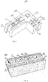
- the corner block 200 is generally L-shaped and includes a first straight edge portion 201, a second straight edge portion 202 and a corner portion 203 connected between the first straight edge portion 201 and the second straight edge portion 202.
- the corner portion 203 is formed by connecting two edges with an angle of approximately 90° therebetween. Therefore, the first straight edge portion 201 extends in a direction perpendicular to an extension direction of the second straight edge portion 202.
- a concave structure 10 is concaved from one end of the first straight edge portion 201 away from the corner portion 203.
- the concave structure 10 is also formed at an end of the second straight edge portion 202 away from the corner portion 203 and recessed inwards, and the concave structure 10 is configured for forming an interlocking structure when being latched with other blocks.
- the corner block 200 includes an upper convex structure 11 arranged on a top face of the corner block 200 and a lower concave structure 12 arranged on a bottom face of the corner block 200.
- the upper convex structure 11 extends along a length direction of the top face, with a length of the upper convex structure equal to a length of the top face.
- the upper convex structure 11 extends from the top face of the first straight edge portion 201 to the top face of the second straight edge portion 202 through the top face of the corner portion 203, namely, the upper convex structure 11 extends along the length direction of the top face of the whole corner block 200 to form an integrally non-interrupted structure.
- the lower concave structure 12 is a groove extending along the length direction of the bottom face of the whole corner block 200, by recessing from the bottom face to the top face, and specifically, the lower concave structure 12 extends from the bottom face of the first straight edge portion 201 to the bottom face of the second straight edge portion 202 through the bottom face of the corner portion 203.
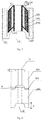
- the upper convex structure 11 is received in the lower concave structure 12 of the adjacent block, so as to realize the interlocking of the two blocks. It can be understood that, referring to FIG.
- a height H of the upper convex structure 11 is smaller than a depth D of the lower concave structure 12, so that when the upper convex structure 11 is received in the lower concave structure 12, so as to form a gap between the upper convex structure 11 and the lower convex structure 12, and the gap forms a horizontal line pipe slot 8 for receiving water supply pipes, electric wires, communication cables and the like, in the horizontal direction.
- the upper convex structure 11 includes a pair of guiding faces 111 extending and inclined from the top face of the corner block 200, and a connecting face 112 connected between the pair of guiding faces.
- the pair of guiding faces 111 extend towards each other, each guiding face 111 connected with the top face at an inclined angle, wherein the inclined angle is greater than 90 degrees and smaller than 180 degrees.
- the guiding face of the upper convex structure is inclined to the top face, it can be effectively achieved to prevent water from entering the block from the top face.
- the guiding face is an inclined face, a better cooperation with the lower concave structure can be realized, so as to obtain effects of guiding and positioning.
- the corner block 200 further includes a positioning groove formed by removing the upper convex structure 11 on the top face of the corner portion 203.
- the positioning groove is configured for accommodating the bottom face of another corner block stacked on the corner block, in particular the bottom face of the corner portion, so as to facilitate mutual cooperation and avoid a mutual interference when the two corner blocks are stacked.
- the positioning groove includes a first positioning groove 161 adjacent to the first straight edge portion 201 and a second positioning groove 162 adjacent to the second straight edge portion 202, and the first positioning groove 161 and the second positioning groove 162 are configured at intervals.
- the upper convex structure 11 further includes a pair of arc-shaped faces 113 connected between the connecting face 112 and the guiding face 111, so that the connecting face 112 is smoothly transited to the connecting face 111 to reduce stress concentration, further to prevent the upper convex structure from being damaged in the transportation process.
- the connecting face 113 has a cross section in shape of 1/4 arc. Accordingly, the shape of the lower concave structure 12 is matched with the shape of the upper convex structure 11 so as to better receive the upper convex structure.
- the corner block 200 further includes a plurality of positioning holes 7 and power cable holes 6 formed in the upper convex structure 11.
- the plurality of positioning holes 7 and the power cable holes 6 extend from the connecting face 112 of the upper convex structure 11 to the bottom face of the corner block.
- the plurality of positioning holes 7 and the power cable holes 6 are configured at intervals, and each line pipe hole 6 is located between two adjacent positioning holes 7.
- the power cable holes 6 are generally circular, rectangular and the like.
- the positioning holes 7 are generally circular, rectangular and the like, with an inner diameter of the positioning hole 7 larger than an inner diameter of the line pipe hole 6.
- the positioning hole 7 is configured for receiving the reinforcing positioning rod 400, and the reinforcing positioning rod 400 is movable and can be pulled out from the positioning hole 7 when needed.
- the power cable holes 6 are configured for receiving electric wires, water supply pipes, communication cables and the like.
- the corner block 200 further includes thermal insulating holes 17 formed in the top face and located on two opposite sides of the upper convex structure 11.
- the thermal insulating holes 17 are configured to be filled with thermal insulation and sound insulation materials.
- the thermal insulating holes 17 extend from the top face of the corner block 200 to the bottom face of the corner block 200.
- the corner block 200 is not provided with the thermal insulating hole, while the line pipe hole 6 is configured on the top face of the corner block 200, and extends from the top face to the bottom face.
- the plurality of power cable holes 6 are configured on the two sides of the upper convex structure 11.
- the corner block 200 includes a block body 2001, a core 2002 embedded into the block body 2001, and a waterproof layer 2003 between the block body 2001 and the core 2002, a thermal insulating layer 2004 between the waterproof layer 2003 and the core 2002, and a supporting member 2005 fixedly connected with the waterproof layer 2003, wherein the supporting member 2005 is embedded in the block body 2001.
- the waterproof layer 2003 can be a waterproof film and is configured to warp the core 2002; and the supporting member 2005 is configured for supporting the waterproof layer 2003.
- the supporting member 2005 can be a claw-shaped element made of metal, so as to support the waterproof layer 2003 in a large area, and a stretching rib is provided inside the supporting member 2005, so that the waterproof layer 2003 may flatly warp the outer peripheral surfaces of the core 2002 and the thermal insulating layer 2004 under the support of the supporting member 2005.
- the supporting member can be formed in mixing with the block body, so as to enhance the strength of the block.
- the thermal insulating layer 2004 is configured inside the waterproof layer 2003, to achieve a better thermal insulating effect.
- the thermal insulating layer 2004 is made of a thermal insulation material such as sponge.
- the core 2002 can be made of a thermal insulation material, or can also be made of a bulletproof material with relatively high strength, such as high-strength ceramic and the like. In addition, the core 2002 can be made of the same material as the block body 2001.
- the corner block 200 further includes an internal sleeve 207 embedded in the line pipe hole 6 and/or the positioning hole 7.
- the internal sleeve 207 may keep the inner face of the line pipe hole or the positioning hole smooth, to facilitate the insertion or disassembly of the line pipe or the reinforcement positioning rod.
- a decorative layer 13 can be connected to one side or two sides of the corner block 200, wherein colors, and patterns of the decorative layer 13 may be integrally formed with the blocks, or being jointed together with the blocks into a whole after being manufactured separately, and may be only single-side decoration.
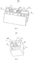
- the structure of the first block 100 is similar to that of the corner block 200. The difference is that the structure of the first block 100 is substantially in straight line, and one end of the first block 100 is a convex structure 9, and the other end of the front convex structure is a concave structure.
- the convex structure is configured for matching with the concave structure of the adjacent block to form an interlocking structure during stacking.
- the first block 100 also has an integrally non-interrupted upper convex structure 11 and a lower concave structure 12, the upper convex structure 11 also has a pair of guiding faces 111 which extend inclined to the top face of the first block, a connecting face 112 and an arc-shaped face 113.
- the first block 100 also includes a plurality of positioning holes 7 and power cable holes 6, and the power cable holes 6 can also be configured on the two sides of the upper convex structure 11.
- An internal sleeve 207 is provided in the line pipe hole 6 and/or the positioning hole 7, and the first block 100 also includes a block body 2001, a core 2002, a waterproof layer 2003 located between the core 2002 and the block body 2001, a thermal insulating layer 2004 located between the waterproof layer 2003 and the core 2002, and a supporting member 2005 fixedly connected with the waterproof layer 2003.
- a decorative layer 13 can be connected to one side or two sides of the first block 100, wherein colors and patterns of the decorative layer 13 may be integrally formed with the blocks, or being jointed together with the blocks into a whole after being manufactured separately, and may be only single-side decoration.
- the structure of the adjusting block 300 is similar to that of the corner block 200. The difference is that the structure of the adjusting block 300 is substantially in straight line, and one end of the adjusting block 300 is a planar face 301, while the other end is a concave structure 10.
- the concave structure 10 is configured for matching with the convex structure 9 of an adjacent block to form an interlocking structure during stacking.
- the adjusting block 300 also has an integrally non-interrupted upper convex structure 11 and a lower concave structure 12, the upper convex structure 11 is also provided with a pair of guiding faces 111 which extend inclined to the top face of the adjusting block, a connecting face 112 and an arc-shaped face 113.
- the adjusting block 300 also includes a plurality of positioning holes 7 and power cable holes 6, and the power cable holes 6 are also configured on the two sides of the upper convex structure 11.
- An internal sleeve 207 is provided in the line pipe hole 6 and/or the positioning hole 7, and the block 300 also includes a block body 2001, a core 2002, a waterproof layer 2003 located between the core 2002 and the block body 2001, a thermal insulating layer 2004 located between the waterproof layer and the core, and a supporting member 2005 fixedly connected with the waterproof layer 2003.
- a decorative layer can be connected to one side or two sides of the adjusting block 300, wherein colors and patterns of the decorative layer 13 may be integrally formed with the blocks, or being jointed together with the blocks into a whole after being manufactured separately, and may be only single-side decoration.
- each block in the block kit is as follows.
- a length of the first block 100 is denoted by L
- a width of the first block 100 is denoted by W
- An outer length of the corner block 200 is L + W
- an inner length of the corner block 200 is L
- an outer width is 1/2L + W
- an inner width is 1/2L
- the adjusting block 4300 has a length of 1/2L, and a width of W.
- the main dimensions of other blocks corresponding to the first blocks with different widths and different lengths can be obtained based on the above calculation formulas, and the related dimensions allow a tolerance of ⁇ 50 mm when the blocks are actually manufactured, so as to realize a complete matching of the blocks.
Landscapes
- Engineering & Computer Science (AREA)
- Architecture (AREA)
- Civil Engineering (AREA)
- Structural Engineering (AREA)
- Physics & Mathematics (AREA)
- Electromagnetism (AREA)
- Finishing Walls (AREA)
- Installation Of Indoor Wiring (AREA)
- Building Environments (AREA)
Applications Claiming Priority (3)
| Application Number | Priority Date | Filing Date | Title |
|---|---|---|---|
| CN201720471364 | 2017-05-02 | ||
| CN201720967874 | 2017-07-27 | ||
| PCT/CN2018/085116 WO2018202011A1 (fr) | 2017-05-02 | 2018-04-28 | Bloc d'angle et kit de bloc le comprenant |
Publications (3)
| Publication Number | Publication Date |
|---|---|
| EP3620587A1 true EP3620587A1 (fr) | 2020-03-11 |
| EP3620587A4 EP3620587A4 (fr) | 2020-05-20 |
| EP3620587B1 EP3620587B1 (fr) | 2021-11-24 |
Family
ID=62955456
Family Applications (1)
| Application Number | Title | Priority Date | Filing Date |
|---|---|---|---|
| EP18794808.8A Not-in-force EP3620587B1 (fr) | 2017-05-02 | 2018-04-28 | Bloc d'angle et kit de bloc le comprenant |
Country Status (4)
| Country | Link |
|---|---|
| EP (1) | EP3620587B1 (fr) |
| CN (2) | CN108343190A (fr) |
| WO (1) | WO2018202011A1 (fr) |
| ZA (1) | ZA201907625B (fr) |
Families Citing this family (2)
| Publication number | Priority date | Publication date | Assignee | Title |
|---|---|---|---|---|
| EP3620587B1 (fr) * | 2017-05-02 | 2021-11-24 | Shenzhen MYX PC Blocks Co Ltd. | Bloc d'angle et kit de bloc le comprenant |
| CN109083302A (zh) * | 2018-08-23 | 2018-12-25 | 深圳市新天能科技开发有限公司 | 墙柱梁一体式的装配式建筑方法 |
Family Cites Families (19)
| Publication number | Priority date | Publication date | Assignee | Title |
|---|---|---|---|---|
| CN2074329U (zh) * | 1990-07-16 | 1991-04-03 | 史世英 | 多功能连锁砌块(砖) |
| CN1070711A (zh) * | 1992-09-23 | 1993-04-07 | 卫龙武 | 抗震保温砌块及其制造 |
| JPH11343686A (ja) * | 1998-06-01 | 1999-12-14 | Kunio Hiyama | 煉瓦並びに煉瓦積用理込型引掛受具 |
| CA2285832C (fr) * | 1999-10-13 | 2005-09-20 | Tony J. Azar | Briques sans mortier |
| CN2641186Y (zh) * | 2003-08-27 | 2004-09-15 | 广州子光建材开发有限公司 | 一种自动正位的混凝土双孔空心砌块 |
| CN201567690U (zh) * | 2009-12-18 | 2010-09-01 | 周央娣 | 一种预制式承重保温复合板 |
| KR101154074B1 (ko) * | 2010-02-04 | 2012-06-11 | 정만영 | 단열성, 차수성, 시공성이 개선된 쪽매형 벽돌 및 그 벽돌을 이용한 시공방법 |
| CN103161252A (zh) * | 2011-12-09 | 2013-06-19 | 天津市金三农农业科技开发有限公司 | 在戈壁滩上使用的空心砖 |
| CN203947664U (zh) * | 2014-01-13 | 2014-11-19 | 北京奥润开元环保科技研究院有限公司 | 轻质建筑垃圾环保墙体砌块 |
| CN204225340U (zh) * | 2014-10-11 | 2015-03-25 | 屠财荣 | 一种凹凸斜缝多孔砖 |
| US9677267B2 (en) * | 2014-10-15 | 2017-06-13 | Block Florida, LLC | Construction blocks and systems |
| CN204728562U (zh) * | 2015-04-16 | 2015-10-28 | 黄烈元 | 一种建筑用砖、由该砖建成的带拐角的墙 |
| CN204703362U (zh) * | 2015-05-08 | 2015-10-14 | 常州华光建材科技有限公司 | 灌注型防火保温砌块 |
| CN204826374U (zh) * | 2015-08-05 | 2015-12-02 | 符东华 | 一种防水墙砖 |
| CN205369667U (zh) * | 2015-12-31 | 2016-07-06 | 淮南金科再生资源利用有限公司 | 建筑垃圾再生的用于砌体拐角砌筑的直槽空心保温砌块 |
| CN205475995U (zh) * | 2016-01-20 | 2016-08-17 | 十九冶成都建设有限公司 | 保温砌块 |
| CN205577165U (zh) * | 2016-02-15 | 2016-09-14 | 黄佳财 | 绿建材轻隔间陶砖 |
| CN205653972U (zh) * | 2016-02-17 | 2016-10-19 | 深圳市新天能科技开发有限公司 | 一种环保建筑结构套件 |
| EP3620587B1 (fr) * | 2017-05-02 | 2021-11-24 | Shenzhen MYX PC Blocks Co Ltd. | Bloc d'angle et kit de bloc le comprenant |
-
2018
- 2018-04-28 EP EP18794808.8A patent/EP3620587B1/fr not_active Not-in-force
- 2018-04-28 CN CN201810401546.6A patent/CN108343190A/zh active Pending
- 2018-04-28 CN CN201820640712.3U patent/CN208441335U/zh not_active Expired - Fee Related
- 2018-04-28 WO PCT/CN2018/085116 patent/WO2018202011A1/fr not_active Ceased
-
2019
- 2019-11-18 ZA ZA2019/07625A patent/ZA201907625B/en unknown
Also Published As
| Publication number | Publication date |
|---|---|
| EP3620587B1 (fr) | 2021-11-24 |
| WO2018202011A1 (fr) | 2018-11-08 |
| EP3620587A4 (fr) | 2020-05-20 |
| CN108343190A (zh) | 2018-07-31 |
| CN208441335U (zh) | 2019-01-29 |
| ZA201907625B (en) | 2021-02-24 |
Similar Documents
| Publication | Publication Date | Title |
|---|---|---|
| US10526783B2 (en) | Recyclable building block and building system used for constructing building | |
| CA2502343A1 (fr) | Paroi de coffrage remplissable de beton | |
| US10889983B2 (en) | Recyclable builidng block and building system used for constructing building | |
| CN104294993A (zh) | 一种建筑用砖和由该砖建成的墙体 | |
| EP3620587B1 (fr) | Bloc d'angle et kit de bloc le comprenant | |
| CN110453882A (zh) | 一种装配式spc复合瓷砖的铺贴结构 | |
| CN103526868A (zh) | 装配化建筑楼板及其构成的建筑及建造方法 | |
| US2397119A (en) | Masonry structure and units used therewith | |
| US20110271594A1 (en) | Precast radiation protection board | |
| CN203856111U (zh) | 一种建筑幕墙夹芯板 | |
| CN204112570U (zh) | 一种建筑用砖和由该砖建成的墙体 | |
| CN214784853U (zh) | 一种整覆式柔性防水型材 | |
| TWI342914B (fr) | ||
| CN210917925U (zh) | 一种新型建筑用砖 | |
| CN212613478U (zh) | 一种瓷砖壁板阳角连接结构 | |
| CN214034487U (zh) | 一种用于墙体阴阳角定型的构件 | |
| CN110528773A (zh) | 一种新型建筑用砖 | |
| CN201420348Y (zh) | 免粉刷多功能砖 | |
| CN214364364U (zh) | 一种预制成型的砌块及使用该砌块的墙体 | |
| CN205090097U (zh) | 砌体墙穿管线结构 | |
| CN216275511U (zh) | 带装饰面的预制件及景观水沟 | |
| CN206467875U (zh) | 一种带装饰面的积木式保温建筑结构件 | |
| CN210563102U (zh) | 一种仿古建筑墙面的陶瓷外墙砖 | |
| CN218779712U (zh) | 快装型建筑砖 | |
| CN222862763U (zh) | 一种装饰方砖 |
Legal Events
| Date | Code | Title | Description |
|---|---|---|---|
| STAA | Information on the status of an ep patent application or granted ep patent |
Free format text: STATUS: THE INTERNATIONAL PUBLICATION HAS BEEN MADE |
|
| PUAI | Public reference made under article 153(3) epc to a published international application that has entered the european phase |
Free format text: ORIGINAL CODE: 0009012 |
|
| STAA | Information on the status of an ep patent application or granted ep patent |
Free format text: STATUS: REQUEST FOR EXAMINATION WAS MADE |
|
| 17P | Request for examination filed |
Effective date: 20191202 |
|
| AK | Designated contracting states |
Kind code of ref document: A1 Designated state(s): AL AT BE BG CH CY CZ DE DK EE ES FI FR GB GR HR HU IE IS IT LI LT LU LV MC MK MT NL NO PL PT RO RS SE SI SK SM TR |
|
| AX | Request for extension of the european patent |
Extension state: BA ME |
|
| A4 | Supplementary search report drawn up and despatched |
Effective date: 20200420 |
|
| RIC1 | Information provided on ipc code assigned before grant |
Ipc: E04B 2/46 20060101ALI20200414BHEP Ipc: E04C 1/00 20060101AFI20200414BHEP Ipc: E04B 2/50 20060101ALI20200414BHEP Ipc: E04C 1/39 20060101ALI20200414BHEP Ipc: E04B 2/52 20060101ALI20200414BHEP |
|
| DAV | Request for validation of the european patent (deleted) | ||
| DAX | Request for extension of the european patent (deleted) | ||
| GRAP | Despatch of communication of intention to grant a patent |
Free format text: ORIGINAL CODE: EPIDOSNIGR1 |
|
| STAA | Information on the status of an ep patent application or granted ep patent |
Free format text: STATUS: GRANT OF PATENT IS INTENDED |
|
| INTG | Intention to grant announced |
Effective date: 20210721 |
|
| GRAS | Grant fee paid |
Free format text: ORIGINAL CODE: EPIDOSNIGR3 |
|
| GRAA | (expected) grant |
Free format text: ORIGINAL CODE: 0009210 |
|
| STAA | Information on the status of an ep patent application or granted ep patent |
Free format text: STATUS: THE PATENT HAS BEEN GRANTED |
|
| AK | Designated contracting states |
Kind code of ref document: B1 Designated state(s): AL AT BE BG CH CY CZ DE DK EE ES FI FR GB GR HR HU IE IS IT LI LT LU LV MC MK MT NL NO PL PT RO RS SE SI SK SM TR |
|
| REG | Reference to a national code |
Ref country code: GB Ref legal event code: FG4D |
|
| REG | Reference to a national code |
Ref country code: AT Ref legal event code: REF Ref document number: 1449977 Country of ref document: AT Kind code of ref document: T Effective date: 20211215 |
|
| REG | Reference to a national code |
Ref country code: DE Ref legal event code: R096 Ref document number: 602018027237 Country of ref document: DE |
|
| REG | Reference to a national code |
Ref country code: IE Ref legal event code: FG4D |
|
| REG | Reference to a national code |
Ref country code: LT Ref legal event code: MG9D |
|
| REG | Reference to a national code |
Ref country code: NL Ref legal event code: MP Effective date: 20211124 |
|
| REG | Reference to a national code |
Ref country code: AT Ref legal event code: MK05 Ref document number: 1449977 Country of ref document: AT Kind code of ref document: T Effective date: 20211124 |
|
| PG25 | Lapsed in a contracting state [announced via postgrant information from national office to epo] |
Ref country code: RS Free format text: LAPSE BECAUSE OF FAILURE TO SUBMIT A TRANSLATION OF THE DESCRIPTION OR TO PAY THE FEE WITHIN THE PRESCRIBED TIME-LIMIT Effective date: 20211124 Ref country code: LT Free format text: LAPSE BECAUSE OF FAILURE TO SUBMIT A TRANSLATION OF THE DESCRIPTION OR TO PAY THE FEE WITHIN THE PRESCRIBED TIME-LIMIT Effective date: 20211124 Ref country code: FI Free format text: LAPSE BECAUSE OF FAILURE TO SUBMIT A TRANSLATION OF THE DESCRIPTION OR TO PAY THE FEE WITHIN THE PRESCRIBED TIME-LIMIT Effective date: 20211124 Ref country code: BG Free format text: LAPSE BECAUSE OF FAILURE TO SUBMIT A TRANSLATION OF THE DESCRIPTION OR TO PAY THE FEE WITHIN THE PRESCRIBED TIME-LIMIT Effective date: 20220224 Ref country code: AT Free format text: LAPSE BECAUSE OF FAILURE TO SUBMIT A TRANSLATION OF THE DESCRIPTION OR TO PAY THE FEE WITHIN THE PRESCRIBED TIME-LIMIT Effective date: 20211124 |
|
| PG25 | Lapsed in a contracting state [announced via postgrant information from national office to epo] |
Ref country code: IS Free format text: LAPSE BECAUSE OF FAILURE TO SUBMIT A TRANSLATION OF THE DESCRIPTION OR TO PAY THE FEE WITHIN THE PRESCRIBED TIME-LIMIT Effective date: 20220324 Ref country code: SE Free format text: LAPSE BECAUSE OF FAILURE TO SUBMIT A TRANSLATION OF THE DESCRIPTION OR TO PAY THE FEE WITHIN THE PRESCRIBED TIME-LIMIT Effective date: 20211124 Ref country code: PT Free format text: LAPSE BECAUSE OF FAILURE TO SUBMIT A TRANSLATION OF THE DESCRIPTION OR TO PAY THE FEE WITHIN THE PRESCRIBED TIME-LIMIT Effective date: 20220324 Ref country code: PL Free format text: LAPSE BECAUSE OF FAILURE TO SUBMIT A TRANSLATION OF THE DESCRIPTION OR TO PAY THE FEE WITHIN THE PRESCRIBED TIME-LIMIT Effective date: 20211124 Ref country code: NO Free format text: LAPSE BECAUSE OF FAILURE TO SUBMIT A TRANSLATION OF THE DESCRIPTION OR TO PAY THE FEE WITHIN THE PRESCRIBED TIME-LIMIT Effective date: 20220224 Ref country code: NL Free format text: LAPSE BECAUSE OF FAILURE TO SUBMIT A TRANSLATION OF THE DESCRIPTION OR TO PAY THE FEE WITHIN THE PRESCRIBED TIME-LIMIT Effective date: 20211124 Ref country code: LV Free format text: LAPSE BECAUSE OF FAILURE TO SUBMIT A TRANSLATION OF THE DESCRIPTION OR TO PAY THE FEE WITHIN THE PRESCRIBED TIME-LIMIT Effective date: 20211124 Ref country code: HR Free format text: LAPSE BECAUSE OF FAILURE TO SUBMIT A TRANSLATION OF THE DESCRIPTION OR TO PAY THE FEE WITHIN THE PRESCRIBED TIME-LIMIT Effective date: 20211124 Ref country code: GR Free format text: LAPSE BECAUSE OF FAILURE TO SUBMIT A TRANSLATION OF THE DESCRIPTION OR TO PAY THE FEE WITHIN THE PRESCRIBED TIME-LIMIT Effective date: 20220225 Ref country code: ES Free format text: LAPSE BECAUSE OF FAILURE TO SUBMIT A TRANSLATION OF THE DESCRIPTION OR TO PAY THE FEE WITHIN THE PRESCRIBED TIME-LIMIT Effective date: 20211124 |
|
| PG25 | Lapsed in a contracting state [announced via postgrant information from national office to epo] |
Ref country code: SM Free format text: LAPSE BECAUSE OF FAILURE TO SUBMIT A TRANSLATION OF THE DESCRIPTION OR TO PAY THE FEE WITHIN THE PRESCRIBED TIME-LIMIT Effective date: 20211124 Ref country code: SK Free format text: LAPSE BECAUSE OF FAILURE TO SUBMIT A TRANSLATION OF THE DESCRIPTION OR TO PAY THE FEE WITHIN THE PRESCRIBED TIME-LIMIT Effective date: 20211124 Ref country code: RO Free format text: LAPSE BECAUSE OF FAILURE TO SUBMIT A TRANSLATION OF THE DESCRIPTION OR TO PAY THE FEE WITHIN THE PRESCRIBED TIME-LIMIT Effective date: 20211124 Ref country code: EE Free format text: LAPSE BECAUSE OF FAILURE TO SUBMIT A TRANSLATION OF THE DESCRIPTION OR TO PAY THE FEE WITHIN THE PRESCRIBED TIME-LIMIT Effective date: 20211124 Ref country code: DK Free format text: LAPSE BECAUSE OF FAILURE TO SUBMIT A TRANSLATION OF THE DESCRIPTION OR TO PAY THE FEE WITHIN THE PRESCRIBED TIME-LIMIT Effective date: 20211124 Ref country code: CZ Free format text: LAPSE BECAUSE OF FAILURE TO SUBMIT A TRANSLATION OF THE DESCRIPTION OR TO PAY THE FEE WITHIN THE PRESCRIBED TIME-LIMIT Effective date: 20211124 |
|
| REG | Reference to a national code |
Ref country code: DE Ref legal event code: R097 Ref document number: 602018027237 Country of ref document: DE |
|
| PLBE | No opposition filed within time limit |
Free format text: ORIGINAL CODE: 0009261 |
|
| STAA | Information on the status of an ep patent application or granted ep patent |
Free format text: STATUS: NO OPPOSITION FILED WITHIN TIME LIMIT |
|
| PG25 | Lapsed in a contracting state [announced via postgrant information from national office to epo] |
Ref country code: AL Free format text: LAPSE BECAUSE OF FAILURE TO SUBMIT A TRANSLATION OF THE DESCRIPTION OR TO PAY THE FEE WITHIN THE PRESCRIBED TIME-LIMIT Effective date: 20211124 |
|
| 26N | No opposition filed |
Effective date: 20220825 |
|
| REG | Reference to a national code |
Ref country code: DE Ref legal event code: R119 Ref document number: 602018027237 Country of ref document: DE |
|
| PG25 | Lapsed in a contracting state [announced via postgrant information from national office to epo] |
Ref country code: SI Free format text: LAPSE BECAUSE OF FAILURE TO SUBMIT A TRANSLATION OF THE DESCRIPTION OR TO PAY THE FEE WITHIN THE PRESCRIBED TIME-LIMIT Effective date: 20211124 |
|
| REG | Reference to a national code |
Ref country code: CH Ref legal event code: PL |
|
| GBPC | Gb: european patent ceased through non-payment of renewal fee |
Effective date: 20220428 |
|
| REG | Reference to a national code |
Ref country code: BE Ref legal event code: MM Effective date: 20220430 |
|
| PG25 | Lapsed in a contracting state [announced via postgrant information from national office to epo] |
Ref country code: MC Free format text: LAPSE BECAUSE OF FAILURE TO SUBMIT A TRANSLATION OF THE DESCRIPTION OR TO PAY THE FEE WITHIN THE PRESCRIBED TIME-LIMIT Effective date: 20211124 Ref country code: LU Free format text: LAPSE BECAUSE OF NON-PAYMENT OF DUE FEES Effective date: 20220428 Ref country code: LI Free format text: LAPSE BECAUSE OF NON-PAYMENT OF DUE FEES Effective date: 20220430 Ref country code: GB Free format text: LAPSE BECAUSE OF NON-PAYMENT OF DUE FEES Effective date: 20220428 Ref country code: FR Free format text: LAPSE BECAUSE OF NON-PAYMENT OF DUE FEES Effective date: 20220430 Ref country code: DE Free format text: LAPSE BECAUSE OF NON-PAYMENT OF DUE FEES Effective date: 20221103 Ref country code: CH Free format text: LAPSE BECAUSE OF NON-PAYMENT OF DUE FEES Effective date: 20220430 |
|
| PG25 | Lapsed in a contracting state [announced via postgrant information from national office to epo] |
Ref country code: BE Free format text: LAPSE BECAUSE OF NON-PAYMENT OF DUE FEES Effective date: 20220430 |
|
| PG25 | Lapsed in a contracting state [announced via postgrant information from national office to epo] |
Ref country code: IE Free format text: LAPSE BECAUSE OF NON-PAYMENT OF DUE FEES Effective date: 20220428 |
|
| PG25 | Lapsed in a contracting state [announced via postgrant information from national office to epo] |
Ref country code: IT Free format text: LAPSE BECAUSE OF FAILURE TO SUBMIT A TRANSLATION OF THE DESCRIPTION OR TO PAY THE FEE WITHIN THE PRESCRIBED TIME-LIMIT Effective date: 20211124 |
|
| PG25 | Lapsed in a contracting state [announced via postgrant information from national office to epo] |
Ref country code: MK Free format text: LAPSE BECAUSE OF FAILURE TO SUBMIT A TRANSLATION OF THE DESCRIPTION OR TO PAY THE FEE WITHIN THE PRESCRIBED TIME-LIMIT Effective date: 20211124 Ref country code: CY Free format text: LAPSE BECAUSE OF FAILURE TO SUBMIT A TRANSLATION OF THE DESCRIPTION OR TO PAY THE FEE WITHIN THE PRESCRIBED TIME-LIMIT Effective date: 20211124 |
|
| PG25 | Lapsed in a contracting state [announced via postgrant information from national office to epo] |
Ref country code: HU Free format text: LAPSE BECAUSE OF FAILURE TO SUBMIT A TRANSLATION OF THE DESCRIPTION OR TO PAY THE FEE WITHIN THE PRESCRIBED TIME-LIMIT; INVALID AB INITIO Effective date: 20180428 |
|
| PG25 | Lapsed in a contracting state [announced via postgrant information from national office to epo] |
Ref country code: MT Free format text: LAPSE BECAUSE OF FAILURE TO SUBMIT A TRANSLATION OF THE DESCRIPTION OR TO PAY THE FEE WITHIN THE PRESCRIBED TIME-LIMIT Effective date: 20211124 |
|
| PG25 | Lapsed in a contracting state [announced via postgrant information from national office to epo] |
Ref country code: TR Free format text: LAPSE BECAUSE OF FAILURE TO SUBMIT A TRANSLATION OF THE DESCRIPTION OR TO PAY THE FEE WITHIN THE PRESCRIBED TIME-LIMIT Effective date: 20211124 |