EP3620602B1 - Dispositif d'ouverture et / ou de fermeture, ainsi que de verrouillage d'un état fermé d'un agencement de fermeture, de fermeture d'une ouverture de chambre, ainsi qu'agencement de fermeture doté d'un tel dispositif - Google Patents
Dispositif d'ouverture et / ou de fermeture, ainsi que de verrouillage d'un état fermé d'un agencement de fermeture, de fermeture d'une ouverture de chambre, ainsi qu'agencement de fermeture doté d'un tel dispositif Download PDFInfo
- Publication number
- EP3620602B1 EP3620602B1 EP18193378.9A EP18193378A EP3620602B1 EP 3620602 B1 EP3620602 B1 EP 3620602B1 EP 18193378 A EP18193378 A EP 18193378A EP 3620602 B1 EP3620602 B1 EP 3620602B1
- Authority
- EP
- European Patent Office
- Prior art keywords
- locking
- housing
- section
- leaf
- chain
- Prior art date
- Legal status (The legal status is an assumption and is not a legal conclusion. Google has not performed a legal analysis and makes no representation as to the accuracy of the status listed.)
- Active
Links
Images


Classifications
-
- E—FIXED CONSTRUCTIONS
- E05—LOCKS; KEYS; WINDOW OR DOOR FITTINGS; SAFES
- E05F—DEVICES FOR MOVING WINGS INTO OPEN OR CLOSED POSITION; CHECKS FOR WINGS; WING FITTINGS NOT OTHERWISE PROVIDED FOR, CONCERNED WITH THE FUNCTIONING OF THE WING
- E05F11/00—Man-operated mechanisms for operating wings, including those which also operate the fastening
- E05F11/02—Man-operated mechanisms for operating wings, including those which also operate the fastening for wings in general, e.g. fanlights
- E05F11/04—Man-operated mechanisms for operating wings, including those which also operate the fastening for wings in general, e.g. fanlights with cords, chains or cables
- E05F11/06—Man-operated mechanisms for operating wings, including those which also operate the fastening for wings in general, e.g. fanlights with cords, chains or cables in guide-channels
-
- E—FIXED CONSTRUCTIONS
- E05—LOCKS; KEYS; WINDOW OR DOOR FITTINGS; SAFES
- E05F—DEVICES FOR MOVING WINGS INTO OPEN OR CLOSED POSITION; CHECKS FOR WINGS; WING FITTINGS NOT OTHERWISE PROVIDED FOR, CONCERNED WITH THE FUNCTIONING OF THE WING
- E05F15/00—Power-operated mechanisms for wings
- E05F15/60—Power-operated mechanisms for wings using electrical actuators
- E05F15/603—Power-operated mechanisms for wings using electrical actuators using rotary electromotors
- E05F15/611—Power-operated mechanisms for wings using electrical actuators using rotary electromotors for swinging wings
- E05F15/616—Power-operated mechanisms for wings using electrical actuators using rotary electromotors for swinging wings operated by push-pull mechanisms
- E05F15/619—Power-operated mechanisms for wings using electrical actuators using rotary electromotors for swinging wings operated by push-pull mechanisms using flexible or rigid rack-and-pinion arrangements
-
- E—FIXED CONSTRUCTIONS
- E05—LOCKS; KEYS; WINDOW OR DOOR FITTINGS; SAFES
- E05Y—INDEXING SCHEME ASSOCIATED WITH SUBCLASSES E05D AND E05F, RELATING TO CONSTRUCTION ELEMENTS, ELECTRIC CONTROL, POWER SUPPLY, POWER SIGNAL OR TRANSMISSION, USER INTERFACES, MOUNTING OR COUPLING, DETAILS, ACCESSORIES, AUXILIARY OPERATIONS NOT OTHERWISE PROVIDED FOR, APPLICATION THEREOF
- E05Y2201/00—Constructional elements; Accessories therefor
- E05Y2201/20—Brakes; Disengaging means; Holders; Stops; Valves; Accessories therefor
- E05Y2201/218—Holders
- E05Y2201/22—Locks
-
- E—FIXED CONSTRUCTIONS
- E05—LOCKS; KEYS; WINDOW OR DOOR FITTINGS; SAFES
- E05Y—INDEXING SCHEME ASSOCIATED WITH SUBCLASSES E05D AND E05F, RELATING TO CONSTRUCTION ELEMENTS, ELECTRIC CONTROL, POWER SUPPLY, POWER SIGNAL OR TRANSMISSION, USER INTERFACES, MOUNTING OR COUPLING, DETAILS, ACCESSORIES, AUXILIARY OPERATIONS NOT OTHERWISE PROVIDED FOR, APPLICATION THEREOF
- E05Y2201/00—Constructional elements; Accessories therefor
- E05Y2201/60—Suspension or transmission members; Accessories therefor
- E05Y2201/622—Suspension or transmission members elements
- E05Y2201/644—Flexible elongated pulling elements
- E05Y2201/656—Chains
-
- E—FIXED CONSTRUCTIONS
- E05—LOCKS; KEYS; WINDOW OR DOOR FITTINGS; SAFES
- E05Y—INDEXING SCHEME ASSOCIATED WITH SUBCLASSES E05D AND E05F, RELATING TO CONSTRUCTION ELEMENTS, ELECTRIC CONTROL, POWER SUPPLY, POWER SIGNAL OR TRANSMISSION, USER INTERFACES, MOUNTING OR COUPLING, DETAILS, ACCESSORIES, AUXILIARY OPERATIONS NOT OTHERWISE PROVIDED FOR, APPLICATION THEREOF
- E05Y2600/00—Mounting or coupling arrangements for elements provided for in this subclass
- E05Y2600/40—Mounting location; Visibility of the elements
- E05Y2600/41—Concealed
-
- E—FIXED CONSTRUCTIONS
- E05—LOCKS; KEYS; WINDOW OR DOOR FITTINGS; SAFES
- E05Y—INDEXING SCHEME ASSOCIATED WITH SUBCLASSES E05D AND E05F, RELATING TO CONSTRUCTION ELEMENTS, ELECTRIC CONTROL, POWER SUPPLY, POWER SIGNAL OR TRANSMISSION, USER INTERFACES, MOUNTING OR COUPLING, DETAILS, ACCESSORIES, AUXILIARY OPERATIONS NOT OTHERWISE PROVIDED FOR, APPLICATION THEREOF
- E05Y2900/00—Application of doors, windows, wings or fittings thereof
- E05Y2900/10—Application of doors, windows, wings or fittings thereof for buildings or parts thereof
- E05Y2900/13—Type of wing
- E05Y2900/148—Windows
Definitions
- the invention relates to a device for opening and / or closing, as well as for locking a closed state of a locking device, for at least partially closing a room opening, for example a turn and / or tilt window, a door or the like, according to the preamble of claim 1 , and a closure device with such a device.
- Such devices can be used to open and / or close windows, doors or as ventilation flaps, in particular if these are installed in hard-to-reach places, for example also in the case of skylights and the like.
- the window In order to ensure tight closure, in particular also under wind load, the window generally has a locking device by means of which the closed state can be locked.
- a separate drive device can be provided for actuating the locking device.
- a device with a locking device of this type is by the EP 2146032 B1 already become known.
- the known device has for opening and / or closing, as well as for locking a closed state of a closure device for at least partial closure of a room opening, for example a window, a door or the like, a drive and a power transmission means which transmits the driving force to the closure device, which can be coupled to a locking device of the locking device.
- the disadvantage of the known device is the large installation space required, which only allows an arrangement outside visible on the window or a door, due to the size of the drive, but in particular due to a separately arranged deflection device in the housing of the device, which in addition to the guide track of the chain building above the guide track of the chain at the height of the Housing has a separate control groove with one of the guide track deviating control cam.
- a tilt and turn window or a door is implemented with the present device, an extension of the housing and the deflection device is required in addition to an increase in the stroke, which also has a disadvantageous effect on the size and costs of the known device.
- the invention is based on the object of providing a device for a turn-tilt sash, tilt sash or turn sash of a window or door of the type mentioned at the beginning, which enables motorized and manual tilting or turning that is simple and inexpensive to manufacture is, can be assembled and adjusted in a simple, fast, safe and precise manner and which avoids the aforementioned disadvantages in terms of size.
- the device for opening and / or closing, as well as for locking a closed state of a locking device, for at least partial locking of a room opening of a turn and / or tilt window or a door with a sash and a frame has a drive and a force transmission means which transmits the drive force to the locking device and which can be coupled to a locking device by means of a locking pin of the locking device.
- the drive can have an electric motor or other motorized drive. Alternatively or in addition, the drive can also take place manually, for example by means of an actuating handle.
- the force transmission means preferably transmits both tensile and compressive forces. In addition this is Power transmission means formed at least in sections by a rigid chain.
- the locking device has a drive rod with a locking or locking pin arranged thereon and is arranged on the wing of the locking device. In the closed state of the locking device, the locking pins engage in correspondingly shaped locking pieces fixed on the frame and thereby lock the closed state of the window or door.
- a driver of the force transmission means facing the locking device is preferably coupled directly to a locking pin and is deflected by a deflection device, starting from a first direction of movement for closing the locking device, in a second direction of movement for actuating the locking device of the locking device.
- the driver when the force transmission means is drawn into a housing, follows the device along an arcuate section of a guide track for the power transmission means.
- the driver rotates at an angle of almost 90 ° around the axis of the locking pin located in the driver, whereby as the guide member is retracted further, the driver becomes the locking device of the locking device with further engagement of the locking pin actuated.
- the power transmission means is designed as a chain, which extends out of the housing when the sash is in the tilted position or rotated position of the sash, displaced by 90 ° in a free section, runs to the direction of movement of the locking device and with passing through the arcuate section in the housing into a linear movement parallel to the direction of movement of the locking device can be transferred.
- the chain is advantageously divided into two sections.
- the first subsection has a driver at its first free end and is designed to transmit tensile and compressive forces with rigid chain links.
- the second free end which ends in the guideway of the housing and forms the second partial section, is formed with standard chain links by eliminating intermediate plates to enable back rigidity.
- the flat arrangement of the chain in the second section with standard chain links formed a contribution to a concealed installation of the chain and thus contribute at least to a concealed arrangement of the device in the window or door.
- the guide member is hinged to the free end of the power transmission means and forms a fixed connection, for example a riveted connection, with the driver.
- a fixed connection for example a riveted connection
- the guide link with an arrangement of lubricants in this embodiment with rollers, forms a leading bearing in the guide track.
- the movable and sometimes rotatable control of the driver is achieved by moving the chain in connection with the guide link in the guide track in the housing.
- the shape of the guide link is preferably adapted to a chain link, sliding rollers being arranged on the respective spaced-apart pin links which are aligned with the guide track of the chain that forms the groove.
- the rectangularly shaped and flat metal driver which can be moved outside the housing.
- the flat design of the driver extends even when the driver moves in a free space on a flat side outside the housing between the housing and the opposite wing.
- a further advantageous embodiment results from the fact that the driver has a U-shaped open cutout on one side for the rotatable reception of the locking pin, the cutout being offset at 90 ° to the chain or the guide member is arranged.
- the opening has a bevel or a radius on the respective side edges. Possible tolerances can thus be compensated for simply and inexpensively.
- Another advantageous handling results from the position of the cutout on the driver for the seat of the locking pin of the locking device before passing through the arcuate section of the power transmission means from an adjacent closed position of the sash to the frame and the tilted position of the locking device.
- the cut-out of the driver lies open in the direction of movement of the locking device of the sash and runs parallel to the guide track of the chain, so that the locking pin can be manually extended from the cut-out, for example with an actuating handle, or with further manual actuation, the lock arranged on a drive rod of the locking device - and locking pins can be moved into a free field of operation, into a rotary open position or into a locked closed position.
- the wing can be moved through from a closed position of the wing to the frame and the tilted position of the locking device, with the opening of the cutout perpendicular to the wing and pointing in the opening direction transversely to the direction of movement of the locking device Manual actuation of the wing of the locking pin by overcoming it from a locking position from the cutout of the driver into a free operating field of a tilted position.
- a stable hold of the back stiffness of the chain under tension during the exit of the chain from the housing and thus the motor-driven extension and retraction of the wing is promoted by a convex nose pointing on the driver to the wing or to the overturning of the wing Force transmission means, in particular the chain, is acted upon with a torque and permanently pushes the chain into a rigid position.
- a position-adjustable spring force can be fastened in an end position in the device housing by means of fastening screws.
- the catch engages with a fixing pin arranged on the locking device and engages with the frame in the closed position of the sash.
- the housing can be designed to be L-shaped in cross section over almost the entire length.
- the flat cross-sectional portion of the housing predominates.
- a concealed arrangement of the device in the rebate space of the window or door can thus be realized with the object according to the invention.
- the motor and a worm which forms the transmission to the gearbox, are housed in a separate vibration-damping housing. Vibration-damping components with the motor and the worm can also be integrated directly into the housing with the gearbox and the control system.
- the device in the housing preferably comprises a frictional connection, for example by means of a threaded pin or a form-fitting connection, for example in the form of a spring element, which, as an emergency release device, moves the motor from the transmission into a disengaged position in order to interrupt the frictional connection between the motor and the transmission.
- FIG. 1 an upper section of a wing 4 and a frame 5 of a window or door 3 is shown, with an inventive and generally in FIG Figures 1 to 16 with 1 designated device in an open tilt position of a turn and / or tilt sash shown in this embodiment in the formation of the window or the door 3, with a locking device 8 arranged on the sash 4 and a force transmission means 7 coupled to it in an exposed position, wherein the device 1 is mounted concealed in a rebate space of the window or the door 3 on the frame 5.
- the device 1 is arranged between the wing 4 and the frame 5.
- the wing 4 and the frame 5 lie opposite one another and with respect to horizontal and vertical spars with rabbet surfaces have interlocking locking elements with locking or locking pins 9 on the locking device 8 and the opposite - not shown - locking parts, one of which is attached to the wing 4 and the other to the frame 5.
- an actuating handle also not shown coupled to the locking device 8
- the locking elements can be moved relative to one another and can be brought into engagement with one another in a closed locking position.
- the present device 1 for opening and / or closing as well as for locking a closed state of the locking device 2, for at least partial closing of a room opening of a turn and / or tilt window 3 or a door with a sash 4 and a frame 5, a Drive 6 and the force transmission means 7 which transmits the drive force to the locking device 2 and which couples the locking device 8 to at least one of the locking pins 9 of the locking device 2.
- FIGS. 1 and 2 show the window or the door 3 in a tilted position exhibited by the device 1 by a motor, the lower horizontal spar of the sash 4 and the frame 5 being arranged adjacent to one another and the upper horizontal spar of the sash 4 to the frame 5 according to the opening distance of the power transmission means 7 from one another spaced apart form a space opening.
- the drive 6 can have an electric motor or other motorized drive. Alternatively or in addition, the drive can also take place manually, for example by means of the actuating handle.
- the force transmission means 7 transmits both tensile and compressive forces.
- the locking or locking pins 9 of the locking device 8 which are arranged displaceably on a drive rod, are -not shown- Sashes 4 facing the locking device 2 and, in the closed state of the locking device 2, engage in correspondingly shaped locking parts fixed on the frame 5 and thereby lock the closed state of the window or door 3.
- a driver 10 of the force transmission means 7 facing the locking device 2 is directly coupled to one of the locking pins 9 of the locking device 8 and is actuated by a deflection device 11 arranged in the housing 14 of the device 1, starting from a first direction of movement 12, for closing the locking device 2 from a Tilt position after Fig. 3 , in a second direction of movement 13 after FIGS. 4 and 5 deflected to actuate the locking device 8 of the locking device 2.
- the driver 10 with further engagement of the locking pin 9, the locking device 8 of the locking device 2 is actuated and moves with a leading course in the guide track 16 with a first partial surface below the housing 14.
- the other, second partial surface of the driver 10 forms the coupling with the locking pin 9 and runs over the length of the travel path, starting from the adjacent tilted position of the wing 4 up to the closed locking position, visible in a recess 36 of the housing 14.
- the power transmission means 7 is designed as a chain.
- the chain 7 When the sash 4 is in the tilted position by means of a motor Fig. 2 and Fig. 3 the chain 7 is extended from the housing 14.
- the chain 7 follows Fig. 3 in a free section offset by 90 ° to the direction of movement of the Locking device 8 and forms the link with the connection of the chain 7 with the first free end 20 in the housing 14 on the drive 6 and with the second free end 21 with the driver 10 in connection with the locking device 8 between the frame 5 and the wing 4.
- Fig. 3 in a free section offset by 90 ° to the direction of movement of the Locking device 8 and forms the link with the connection of the chain 7 with the first free end 20 in the housing 14 on the drive 6 and with the second free end 21 with the driver 10 in connection with the locking device 8 between the frame 5 and the wing 4.
- the chain 7 in the retracted state with the closed position of the sash 4 to the frame 5 and with retention of the driver 10 in a possible rotatable position about the axis 18 of the locking pin 9 Fig. 5
- the chain 7 automatically runs through the circular arc-shaped section 15 in the housing 14 by the motor drive 6 with automatic rotation of the driver 10 by 90 ° and moves in a linear movement parallel to the direction of movement of the locking device 8 with transition to a possible rotational position of the wing 4 for a manual Rotary movement or further passage into a locked closed position of the sash 4 to the frame 5.
- the chain 7 is divided into two sections, a first section with a first free end 20 and the driver 10 arranged thereon consisting of rigid chain links 19 is formed.
- the back-stiff first section of the chain 7 runs in a groove 37 that is enlarged in the guide track 16 and extends from the inlet opening 38 around the deflection device 11 of the guide track 16 at least to the drive 6, facing the direction of movement of the locking device 8.
- the second section of the chain 7, of which the second free end 21 in the guide track 16 on the drive 6 is deflected and parallel spaced from the first section of the first end 20 in a narrow groove 39 below the groove 37, is with the omission of intermediate plates for a back stiffness with standard chain links 22 formed.
- the flat arrangement of the chain 7 in the first section with the standard chain links 22 also forms a small design for concealed installation of the chain 7 and for a concealed arrangement of the device 1 in the window or door 3.
- the guide member 17 is articulated at the free end 20 of the power transmission means 7, which is a fixed connection with the driver 10, for example after Fig. 7 a Riveted connection.
- the guide member 17 is similar in design Fig. 7 a standard chain link, with sliding means in the form of sliding rollers 23 being rotatably mounted on the respective rivet bolts 40.
- the guide link 17 with the sliding rollers 23 forms a leading bearing in the extended guide track 16.
- the movable and sometimes rotatable control of the driver 10 is achieved with the motorized movement of the chain 7 in connection with the guide link 17 in the guide track 16 in the housing 14.
- the driver 10 With the assumption of the guide properties and secured, movable support for the chain 7 and the driver 10 in the guide track 16 of the device 1 by the guide member 17, the driver 10 itself can be formed from a rectangular flat metal or from a flat plastic and is outside of the Housing 14 movably displaceable.
- the flat design of the driver 10 extends even when the driver 10 moves in a free space along a flat side 41 of the housing 14 between the housing 14 and the opposite wing 4 in the rebate space.
- one side of the driver 10 has a U-shaped open cutout 24 for rotatably receiving the locking pin 9, which runs offset at a 90 ° angle to at least one chain link to the chain 7 or the guide link 17.
- the width of the cutout 24 is adapted to the diameter of the locking pin 9.
- the opening has a bevel 35 or a radius on the respective side edges and is designed as an elongated hole for a secure position of the locking pin 9 in length.
- the locking pin 9 In the motorized position of the driver 10 after Fig. 6 , with seat of the locking pin 9 in the driver 10 and the open position of the cutout 24 parallel in the direction of movement of the locking device 8 and the guide track 16 of the chain 7 before passing through the circular arc-shaped section 15 of the power transmission means 7 from a closed position of the sash 4 to the frame 5 and the automatic tilt readiness position, the locking pin 9,
- an actuating handle coupled to the locking device 8 manually control out of the cutout 24 into a rotary open position and manually free from the drive rotary opening or with further manual actuation the locking and locking pins arranged on a drive rod of the locking device 8 in a locked closed position of the window or the door 3 transfer.
- the wing 4 when the locking pin 9 engages with the driver 10, the wing 4 can be positioned in a rotational position of the locking device 8 with further motorized retraction of the power transmission means 7, and the wing 4, likewise with overcoming the locking pin 9, can be manually moved out of the locking position into a rotational position move around.
- a position-positionable and spring-loaded catch 26, which by means of fastening screws 27 after Fig. 8 can be fastened adjustably in an end position, ensures a secure hold during the passage of the device 1 from a tilting and rotating position into a locked closed position of the sash 4 to the frame 5 of the window or the door 3 and vice versa.
- the catch 26 goes during the Motorized travel path of the device 1 with a fixing pin 28 arranged on the locking device 8 engages a connection that latches in the closed position of the sash 4 to the frame 5.
- the housing 14 is L-shaped in cross-section over almost the entire length. In this case, in the proportion of the proportion of the size with the support of the guide track 16 of the housing 14, the flat cross-sectional proportion predominates. A concealed arrangement of the device 1 in the rebate space of the window or of the door 3 can thus be realized with the object according to the invention.
- the motor 29 and a worm 31, which forms the transmission to the gearbox 30, are accommodated in a separate vibration-damping housing 42. Vibration-damping components with the motor 29 and the worm 31 can also be integrated directly with the gear 30 and the control in the housing 14.
- the device 1 in the housing 14 comprises a frictional connection, for example by means of a threaded pin 32, or a form-fitting connection, for example in the form of a spring element 33, which, as an emergency release device 34, moves the motor 29 of the transmission 30 into a disengaged position in order to establish the frictional connection between the motor 29 and the transmission 30 to interrupt.
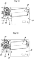
- a further variant embodiment of a driver 10 is disclosed, to which a spring-loaded hook 43 is attached.
- the hook 43 has a web or projection 44 articulated to the wing 4 or to the housing 14, which automatically opens the hook 43 from the motorized tilt position of the wing 4 when the wing 4 hits the closed position for manual actuation of the locking device 8 and with Extending the sash 4 from the closed position, closes automatically securing in the motorized tilt position.
Landscapes
- Power-Operated Mechanisms For Wings (AREA)
Claims (15)
- Dispositif (1) destiné à ouvrir et/ou fermer ainsi qu'à verrouiller un état fermé d'un système de fermeture (2), à fermer au moins partiellement l'ouverture d'un espace d'une fenêtre oscillo-battante ou à ventaux (3) ou d'une porte avec un ventail (4) et un bâti (5), dans lequel le dispositif (1) présente un entraînement (6) et un moyen de transmission de force (7) qui transmet la force d'entraînement au système de fermeture (2) et qui peut être couplé à un système de verrouillage (8) à l'aide d'un tenon de verrouillage (9) du système de fermeture (2), et dans lequel un doigt d'entraînement (10) du moyen de transmission de force (7) qui se trouve en regard du système de fermeture (2) peut, par le biais d'un système de déviation (11), être dévié à partir d'une première direction de déplacement (12) pour fermer le système de fermeture (2) dans une seconde direction de déplacement (13) pour actionner le système de verrouillage (8) du système de fermeture (2),
caractérisé en ce que
le dispositif (1) peut être disposé monté caché dans un espace de pliure entre le bâti (5) et le ventail (4) de la fenêtre (3) ou de la porte, en ce qu'en introduisant un organe de guidage (17) du moyen de transmission de force, qui est articulé sur le doigt d'entraînement (10), dans la partie arquée (15), le doigt d'entraînement (10) peut pivoter selon un angle de presque 90° autour de l'axe (18) du tenon de verrouillage (9) et, en continuant l'insertion de l'organe de guidage (17), le doigt d'entraînement (10) actionne le système de verrouillage (8) du système de fermeture (2) lors de la poursuite de l'engagement du tenon de verrouillage (9). - Dispositif (1) selon la revendication 1,
caractérisé en ce que
le moyen de transmission de force (7) est réalisé sous la forme d'une chaîne qui s'étend de manière déployée depuis le boîtier (14) dans une section libre de manière décalée de 90° par rapport à la direction de déplacement du système de verrouillage (8) dans le cas d'une position basculante ou rotative du ventail (4) ouvert de manière motorisée et peut être guidé avec un passage de la partie arquée (15) dans le boîtier (14) dans un mouvement linéaire parallèle à la direction de déplacement du système de verrouillage (8). - Dispositif (1) selon la revendication 2,
caractérisé en ce que
la première section de la chaîne avec le doigt d'entraînement (10) disposé à l'extrémité libre (20) est réalisée avec des chaînons (19) qui transmettent des forces de traction et de pression de manière rigide et forme, avec la seconde extrémité libre (21) dans le boîtier (14) qui peut pivoter à 180° de manière guidée dans la glissière de guidage (16), une seconde section avec des chaînons standards (22). - Dispositif (1) selon la revendication 1,
caractérisé en ce que
l'organe de guidage (17) qui est articulé à l'extrémité libre (20) du moyen de transmission de force (7) permet un assemblage fixe, par exemple un assemblage par rivetage, avec le doigt d'entraînement (10). - Dispositif (1) selon la revendication 4,
caractérisé en ce que
l'organe de guidage (17) présente des moyens de coulissement, de préférence des rouleaux coulissants (23), qui se déplacent de manière guidée dans la glissière de guidage (16). - Dispositif (1) selon la revendication 1,
caractérisé en ce que
le doigt d'entraînement (10) est réalisé sous la forme d'un métal plat façonné rectangulairement ou à partir d'une matière plastique plate, caché dans l'espace de pliure de la fenêtre (4) ou de la porte et peut être déplacé de manière mobile à l'extérieur du boîtier (14). - Dispositif (1) selon la revendication 1,
caractérisé en ce que
le doigt d'entraînement (10) présente sur un côté une découpe (24) ouverte en forme de U pour recevoir de manière rotative le tenon de verrouillage (9), dans lequel la découpe (24) est disposée de manière décalée selon un angle de 90° par rapport à la chaîne (7) ou la section longitudinale de l'organe de guidage (17). - Dispositif (1) selon la revendication 1,
caractérisé en ce que
le système de verrouillage (8) peut transférer le ventail (4) manuellement dans une position d'ouverture rotative ou dans une position de fermeture verrouillée, par le biais du tenon de verrouillage (9) transporté conjointement dans la découpe (24) du doigt d'entraînement (10), en amont du passage de la partie arquée (15) du moyen de transmission de force (7), depuis une position de fermeture du ventail (4) par rapport au bâti (5) et la position du système de verrouillage (8) formant la position basculante avec la position ouverte de la découpe (24) dans la direction de déplacement du système de verrouillage (8). - Dispositif (1) selon la revendication 1,
caractérisé en ce que
le système de verrouillage (8) transfère le ventail (4) manuellement dans une position basculante, par le biais du tenon de verrouillage (9) transporté conjointement dans la découpe (24) du doigt d'entraînement (10), en aval du passage de la partie arquée (15) du moyen de transmission de force (7) depuis une position de fermeture du ventail (4) par rapport au bâti (5) et la position du système de verrouillage (8) formant la position basculante avec la position ouverte de la découpe (24) orientée perpendiculairement au ventail (4), ou en continuant l'insertion du moyen de transmission de force (7) se déplace dans une position rotative du système de verrouillage (8), et permet une position de mise en bascule ou en rotation manuelle du ventail (4). - Dispositif (1) selon la revendication 1,
caractérisé en ce que
le doigt d'entraînement (10) présente un nez (25) s'appuyant sur le ventail (4), de préférence sur la boucle du ventail (4), pour une rigidité formant une stabilité arrière du moyen de transmission de force (7) qui sollicite le moyen de transmission de force (7), en particulier la chaîne, avec un couple et pousse la chaîne (7) de manière permanente dans une position rigide à l'arrière. - Dispositif (1) selon la revendication 1,
caractérisé en ce que
dans le boîtier (14) du dispositif (1) un loqueteau (26) soumis à une force de ressort et qui peut être positionné en position, peut être fixé de manière ajustée dans une position d'extrémité à l'aide de vis de fixation (27) et avec un tenon de fixation (28) disposé sur le dispositif de verrouillage (8) permet un assemblage par encliquetage dans la position de fermeture du ventail (4) par rapport au bâti (5). - Dispositif (1) selon la revendication 1,
caractérisé en ce que
le boîtier (14) est réalisé en forme de L en coupe transversale sur presque toute la longueur. - Dispositif (1) selon la revendication 1,
caractérisé en ce que
l'entraînement (6) composé d'un moteur (29), d'un engrenage (30) et d'une commande, est reçu dans le boîtier (14) de manière à atténuer les vibrations, dans lequel une vis sans fin (31) forme la transmission du moteur (29) vers l'engrenage (30) et est guidée dans le boîtier (14). - Dispositif (1) selon la revendication 13,
caractérisé en ce que
le moteur (29) peut être amené dans une position de désengagement formant un système de déverrouillage d'urgence (34) par l'engrenage (30) par le biais d'un assemblage par complémentarité de force présent dans le boîtier (14) du dispositif (1), par exemple d'une tige filetée (32), ou d'un assemblage par complémentarité de forme, par exemple d'un élément de ressort (33), pour interrompre la complémentarité de force entre le moteur (29) et l'engrenage (30). - Dispositif (1) selon une ou plusieurs revendications précédentes 7 à 9,
caractérisé en ce que
au niveau du doigt d'entraînement (10) est fixé un crochet (43) soumis à une force de ressort pour ouvrir et fermer automatiquement la découpe (24), lequel avec une traverse (44) présente sur le crochet (43) forme une surface de butée au niveau du ventail (4) ou du boîtier (14).
Priority Applications (1)
| Application Number | Priority Date | Filing Date | Title |
|---|---|---|---|
| EP18193378.9A EP3620602B1 (fr) | 2018-09-10 | 2018-09-10 | Dispositif d'ouverture et / ou de fermeture, ainsi que de verrouillage d'un état fermé d'un agencement de fermeture, de fermeture d'une ouverture de chambre, ainsi qu'agencement de fermeture doté d'un tel dispositif |
Applications Claiming Priority (1)
| Application Number | Priority Date | Filing Date | Title |
|---|---|---|---|
| EP18193378.9A EP3620602B1 (fr) | 2018-09-10 | 2018-09-10 | Dispositif d'ouverture et / ou de fermeture, ainsi que de verrouillage d'un état fermé d'un agencement de fermeture, de fermeture d'une ouverture de chambre, ainsi qu'agencement de fermeture doté d'un tel dispositif |
Publications (2)
| Publication Number | Publication Date |
|---|---|
| EP3620602A1 EP3620602A1 (fr) | 2020-03-11 |
| EP3620602B1 true EP3620602B1 (fr) | 2021-02-17 |
Family
ID=63556176
Family Applications (1)
| Application Number | Title | Priority Date | Filing Date |
|---|---|---|---|
| EP18193378.9A Active EP3620602B1 (fr) | 2018-09-10 | 2018-09-10 | Dispositif d'ouverture et / ou de fermeture, ainsi que de verrouillage d'un état fermé d'un agencement de fermeture, de fermeture d'une ouverture de chambre, ainsi qu'agencement de fermeture doté d'un tel dispositif |
Country Status (1)
| Country | Link |
|---|---|
| EP (1) | EP3620602B1 (fr) |
Cited By (3)
| Publication number | Priority date | Publication date | Assignee | Title |
|---|---|---|---|---|
| EP4080005A1 (fr) * | 2021-04-22 | 2022-10-26 | VKR Holding A/S | Transmission d'actionneur par chaîne dotée d'un support d'entraînement de vis sans fin et d'un palier |
| EP4080004A1 (fr) * | 2021-04-22 | 2022-10-26 | VKR Holding A/S | Entraînement d'actionneur de chaîne doté d'un support et d'éléments amortisseurs |
| EP4080006A1 (fr) * | 2021-04-22 | 2022-10-26 | VKR Holding A/S | Entraînement d'actionneur de chaîne doté d'un roulement et écrou de roulement |
Families Citing this family (3)
| Publication number | Priority date | Publication date | Assignee | Title |
|---|---|---|---|---|
| DE102019007008A1 (de) * | 2019-10-09 | 2021-04-15 | Siegenia-Aubi Kg | Ausstellvorrichtung für ein Dreh-Kipp-Flügel eines Fensters oder einer Tür |
| DE102019007009A1 (de) * | 2019-10-09 | 2021-04-15 | SlEGENlA-AUBl KG | Ausstellvorrichtung für einen Dreh-Kipp-Flügel eines Fensters oder einer Tür |
| DE102024112129A1 (de) * | 2024-04-30 | 2025-10-30 | Geze Gmbh | Antrieb |
Family Cites Families (3)
| Publication number | Priority date | Publication date | Assignee | Title |
|---|---|---|---|---|
| DE10329528A1 (de) * | 2003-06-30 | 2005-02-03 | Geze Gmbh | Verriegelung für den Flügel eines Fensters oder einer Klappe |
| EP2146032B1 (fr) | 2008-07-18 | 2016-08-17 | ROTO FRANK Aktiengesellschaft | Dispositif destiné à ouvrir et/ou fermer ainsi qu'à verrouiller un état fermé d'un dispositif de fermeture destiné à fermer une ouverture de salle ainsi que dispositif de fermeture doté d'un tel dispositif |
| DE202010013187U1 (de) * | 2010-12-22 | 2011-02-17 | Stg-Beikirch Industrieelektronik + Sicherheitstechnik Gmbh & Co. Kg | Anordnung einer Antriebseinheit einer Ausstell- oder Verriegelungseinrichtung |
-
2018
- 2018-09-10 EP EP18193378.9A patent/EP3620602B1/fr active Active
Non-Patent Citations (1)
| Title |
|---|
| None * |
Cited By (3)
| Publication number | Priority date | Publication date | Assignee | Title |
|---|---|---|---|---|
| EP4080005A1 (fr) * | 2021-04-22 | 2022-10-26 | VKR Holding A/S | Transmission d'actionneur par chaîne dotée d'un support d'entraînement de vis sans fin et d'un palier |
| EP4080004A1 (fr) * | 2021-04-22 | 2022-10-26 | VKR Holding A/S | Entraînement d'actionneur de chaîne doté d'un support et d'éléments amortisseurs |
| EP4080006A1 (fr) * | 2021-04-22 | 2022-10-26 | VKR Holding A/S | Entraînement d'actionneur de chaîne doté d'un roulement et écrou de roulement |
Also Published As
| Publication number | Publication date |
|---|---|
| EP3620602A1 (fr) | 2020-03-11 |
Similar Documents
| Publication | Publication Date | Title |
|---|---|---|
| EP3620602B1 (fr) | Dispositif d'ouverture et / ou de fermeture, ainsi que de verrouillage d'un état fermé d'un agencement de fermeture, de fermeture d'une ouverture de chambre, ainsi qu'agencement de fermeture doté d'un tel dispositif | |
| EP2692969B1 (fr) | Engrenage d'un dispositif de verrouillage à crémone, dispositif de verrouillage avec un tel engrenage ainsi que fenêtre, porte ou analogue avec un tel dispositif de verrouillage à crémone | |
| EP4473179B1 (fr) | Dispositif de déplacement pour le déplacement forcé d'un battant, en particulier d'un battant coulissant, d'une fenêtre ou d'une porte | |
| EP4473180B1 (fr) | Dispositif de décalage pour le décalage forcé d'un vantail, en particulier d'un vantail coulissant, d'une fenêtre ou d'une porte | |
| EP2504505B1 (fr) | Ferrure pour un panneau coulissant de fenêtres ou de portes | |
| EP2146032B1 (fr) | Dispositif destiné à ouvrir et/ou fermer ainsi qu'à verrouiller un état fermé d'un dispositif de fermeture destiné à fermer une ouverture de salle ainsi que dispositif de fermeture doté d'un tel dispositif | |
| EP1816298B1 (fr) | Volet repliable coulissante | |
| DE19741728A1 (de) | Ausstellmechanismus | |
| EP3255233B1 (fr) | Entraînement comprenant un dispositif de mise en mouvement pour un vantail coulissant en tant que vantail coulissant et basculant relevable ou vantail coulissant relevable | |
| EP4041975B1 (fr) | Dispositif d'ouverture pour un châssis oscillo-battant d'une fenêtre ou d'une porte | |
| EP2573306B1 (fr) | Fenêtre ou porte | |
| EP1614844A2 (fr) | Dispositif d'articulation | |
| EP0262347B1 (fr) | Dispositif de maintien en position ouverte d'une porte, d'une fenêtre etc. au moins pivotante | |
| EP3211165A1 (fr) | Dispositif d'ouverture d'un vantail oscillo-battant d'une fenêtre ou d'une porte destiné au basculement motorisé et à la rotation et au basculement manuels | |
| EP4421285B1 (fr) | Porte coulissante avec un battant coulissant verrouillable | |
| EP0342420B1 (fr) | Dispositif de fermeture pour porte ou fenêtre coulissantes et pliantes | |
| EP2806090A2 (fr) | Dispositif pour le verrouillage ou le déverrouillage d'un ouvrant coulissant | |
| EP1759081B1 (fr) | Dispositif orientable | |
| EP4041974B1 (fr) | Dispositif d'ouverture destiné à un châssis oscillobasculant d'une fenêtre ou d'une porte | |
| DE102024203222B3 (de) | Beschlaganordnung für ein Fenster, eine Tür oder dergleichen zur Betätigung einer Feststellbremse | |
| EP3626918B1 (fr) | Ferrure pour une fenêtre, fenêtre | |
| WO2025190543A1 (fr) | Procédé pour faciliter l'assemblage et/ou le réglage d'un dispositif d'entraînement pour l'actionnement coulissant d'un vantail coulissant mobile ou d'un vantail de levage et de coulissement d'une fenêtre ou d'une porte | |
| EP4573252A1 (fr) | Dispositif de décalage pour le décalage forcé d'un vantail, en particulier d'un vantail coulissant, d'une fenêtre ou d'une porte | |
| EP1503016A2 (fr) | Dispositif pivot | |
| EP2746507A2 (fr) | Ferrure à crémone dotée d'un dispositif d'anti-fausse manoeuvre et fenêtre, porte ou analogue dotée d'une telle ferrure à crémone |
Legal Events
| Date | Code | Title | Description |
|---|---|---|---|
| PUAI | Public reference made under article 153(3) epc to a published international application that has entered the european phase |
Free format text: ORIGINAL CODE: 0009012 |
|
| STAA | Information on the status of an ep patent application or granted ep patent |
Free format text: STATUS: THE APPLICATION HAS BEEN PUBLISHED |
|
| AK | Designated contracting states |
Kind code of ref document: A1 Designated state(s): AL AT BE BG CH CY CZ DE DK EE ES FI FR GB GR HR HU IE IS IT LI LT LU LV MC MK MT NL NO PL PT RO RS SE SI SK SM TR |
|
| AX | Request for extension of the european patent |
Extension state: BA ME |
|
| STAA | Information on the status of an ep patent application or granted ep patent |
Free format text: STATUS: REQUEST FOR EXAMINATION WAS MADE |
|
| 17P | Request for examination filed |
Effective date: 20200811 |
|
| GRAP | Despatch of communication of intention to grant a patent |
Free format text: ORIGINAL CODE: EPIDOSNIGR1 |
|
| STAA | Information on the status of an ep patent application or granted ep patent |
Free format text: STATUS: GRANT OF PATENT IS INTENDED |
|
| INTG | Intention to grant announced |
Effective date: 20201116 |
|
| GRAS | Grant fee paid |
Free format text: ORIGINAL CODE: EPIDOSNIGR3 |
|
| GRAA | (expected) grant |
Free format text: ORIGINAL CODE: 0009210 |
|
| STAA | Information on the status of an ep patent application or granted ep patent |
Free format text: STATUS: THE PATENT HAS BEEN GRANTED |
|
| AK | Designated contracting states |
Kind code of ref document: B1 Designated state(s): AL AT BE BG CH CY CZ DE DK EE ES FI FR GB GR HR HU IE IS IT LI LT LU LV MC MK MT NL NO PL PT RO RS SE SI SK SM TR |
|
| REG | Reference to a national code |
Ref country code: GB Ref legal event code: FG4D Free format text: NOT ENGLISH |
|
| REG | Reference to a national code |
Ref country code: CH Ref legal event code: EP |
|
| REG | Reference to a national code |
Ref country code: DE Ref legal event code: R096 Ref document number: 502018003891 Country of ref document: DE |
|
| REG | Reference to a national code |
Ref country code: AT Ref legal event code: REF Ref document number: 1361678 Country of ref document: AT Kind code of ref document: T Effective date: 20210315 |
|
| REG | Reference to a national code |
Ref country code: IE Ref legal event code: FG4D Free format text: LANGUAGE OF EP DOCUMENT: GERMAN |
|
| REG | Reference to a national code |
Ref country code: LT Ref legal event code: MG9D |
|
| REG | Reference to a national code |
Ref country code: NL Ref legal event code: MP Effective date: 20210217 |
|
| PG25 | Lapsed in a contracting state [announced via postgrant information from national office to epo] |
Ref country code: BG Free format text: LAPSE BECAUSE OF FAILURE TO SUBMIT A TRANSLATION OF THE DESCRIPTION OR TO PAY THE FEE WITHIN THE PRESCRIBED TIME-LIMIT Effective date: 20210517 Ref country code: FI Free format text: LAPSE BECAUSE OF FAILURE TO SUBMIT A TRANSLATION OF THE DESCRIPTION OR TO PAY THE FEE WITHIN THE PRESCRIBED TIME-LIMIT Effective date: 20210217 Ref country code: HR Free format text: LAPSE BECAUSE OF FAILURE TO SUBMIT A TRANSLATION OF THE DESCRIPTION OR TO PAY THE FEE WITHIN THE PRESCRIBED TIME-LIMIT Effective date: 20210217 Ref country code: GR Free format text: LAPSE BECAUSE OF FAILURE TO SUBMIT A TRANSLATION OF THE DESCRIPTION OR TO PAY THE FEE WITHIN THE PRESCRIBED TIME-LIMIT Effective date: 20210518 Ref country code: NO Free format text: LAPSE BECAUSE OF FAILURE TO SUBMIT A TRANSLATION OF THE DESCRIPTION OR TO PAY THE FEE WITHIN THE PRESCRIBED TIME-LIMIT Effective date: 20210517 Ref country code: PT Free format text: LAPSE BECAUSE OF FAILURE TO SUBMIT A TRANSLATION OF THE DESCRIPTION OR TO PAY THE FEE WITHIN THE PRESCRIBED TIME-LIMIT Effective date: 20210617 Ref country code: LT Free format text: LAPSE BECAUSE OF FAILURE TO SUBMIT A TRANSLATION OF THE DESCRIPTION OR TO PAY THE FEE WITHIN THE PRESCRIBED TIME-LIMIT Effective date: 20210217 |
|
| PG25 | Lapsed in a contracting state [announced via postgrant information from national office to epo] |
Ref country code: SE Free format text: LAPSE BECAUSE OF FAILURE TO SUBMIT A TRANSLATION OF THE DESCRIPTION OR TO PAY THE FEE WITHIN THE PRESCRIBED TIME-LIMIT Effective date: 20210217 Ref country code: PL Free format text: LAPSE BECAUSE OF FAILURE TO SUBMIT A TRANSLATION OF THE DESCRIPTION OR TO PAY THE FEE WITHIN THE PRESCRIBED TIME-LIMIT Effective date: 20210217 Ref country code: LV Free format text: LAPSE BECAUSE OF FAILURE TO SUBMIT A TRANSLATION OF THE DESCRIPTION OR TO PAY THE FEE WITHIN THE PRESCRIBED TIME-LIMIT Effective date: 20210217 Ref country code: RS Free format text: LAPSE BECAUSE OF FAILURE TO SUBMIT A TRANSLATION OF THE DESCRIPTION OR TO PAY THE FEE WITHIN THE PRESCRIBED TIME-LIMIT Effective date: 20210217 Ref country code: NL Free format text: LAPSE BECAUSE OF FAILURE TO SUBMIT A TRANSLATION OF THE DESCRIPTION OR TO PAY THE FEE WITHIN THE PRESCRIBED TIME-LIMIT Effective date: 20210217 |
|
| PG25 | Lapsed in a contracting state [announced via postgrant information from national office to epo] |
Ref country code: IS Free format text: LAPSE BECAUSE OF FAILURE TO SUBMIT A TRANSLATION OF THE DESCRIPTION OR TO PAY THE FEE WITHIN THE PRESCRIBED TIME-LIMIT Effective date: 20210617 |
|
| PG25 | Lapsed in a contracting state [announced via postgrant information from national office to epo] |
Ref country code: SM Free format text: LAPSE BECAUSE OF FAILURE TO SUBMIT A TRANSLATION OF THE DESCRIPTION OR TO PAY THE FEE WITHIN THE PRESCRIBED TIME-LIMIT Effective date: 20210217 Ref country code: CZ Free format text: LAPSE BECAUSE OF FAILURE TO SUBMIT A TRANSLATION OF THE DESCRIPTION OR TO PAY THE FEE WITHIN THE PRESCRIBED TIME-LIMIT Effective date: 20210217 Ref country code: EE Free format text: LAPSE BECAUSE OF FAILURE TO SUBMIT A TRANSLATION OF THE DESCRIPTION OR TO PAY THE FEE WITHIN THE PRESCRIBED TIME-LIMIT Effective date: 20210217 |
|
| REG | Reference to a national code |
Ref country code: DE Ref legal event code: R097 Ref document number: 502018003891 Country of ref document: DE |
|
| PG25 | Lapsed in a contracting state [announced via postgrant information from national office to epo] |
Ref country code: RO Free format text: LAPSE BECAUSE OF FAILURE TO SUBMIT A TRANSLATION OF THE DESCRIPTION OR TO PAY THE FEE WITHIN THE PRESCRIBED TIME-LIMIT Effective date: 20210217 Ref country code: SK Free format text: LAPSE BECAUSE OF FAILURE TO SUBMIT A TRANSLATION OF THE DESCRIPTION OR TO PAY THE FEE WITHIN THE PRESCRIBED TIME-LIMIT Effective date: 20210217 Ref country code: DK Free format text: LAPSE BECAUSE OF FAILURE TO SUBMIT A TRANSLATION OF THE DESCRIPTION OR TO PAY THE FEE WITHIN THE PRESCRIBED TIME-LIMIT Effective date: 20210217 |
|
| PLBE | No opposition filed within time limit |
Free format text: ORIGINAL CODE: 0009261 |
|
| STAA | Information on the status of an ep patent application or granted ep patent |
Free format text: STATUS: NO OPPOSITION FILED WITHIN TIME LIMIT |
|
| 26N | No opposition filed |
Effective date: 20211118 |
|
| PG25 | Lapsed in a contracting state [announced via postgrant information from national office to epo] |
Ref country code: ES Free format text: LAPSE BECAUSE OF FAILURE TO SUBMIT A TRANSLATION OF THE DESCRIPTION OR TO PAY THE FEE WITHIN THE PRESCRIBED TIME-LIMIT Effective date: 20210217 Ref country code: AL Free format text: LAPSE BECAUSE OF FAILURE TO SUBMIT A TRANSLATION OF THE DESCRIPTION OR TO PAY THE FEE WITHIN THE PRESCRIBED TIME-LIMIT Effective date: 20210217 |
|
| PG25 | Lapsed in a contracting state [announced via postgrant information from national office to epo] |
Ref country code: SI Free format text: LAPSE BECAUSE OF FAILURE TO SUBMIT A TRANSLATION OF THE DESCRIPTION OR TO PAY THE FEE WITHIN THE PRESCRIBED TIME-LIMIT Effective date: 20210217 |
|
| PG25 | Lapsed in a contracting state [announced via postgrant information from national office to epo] |
Ref country code: IT Free format text: LAPSE BECAUSE OF FAILURE TO SUBMIT A TRANSLATION OF THE DESCRIPTION OR TO PAY THE FEE WITHIN THE PRESCRIBED TIME-LIMIT Effective date: 20210217 |
|
| REG | Reference to a national code |
Ref country code: BE Ref legal event code: MM Effective date: 20210930 |
|
| PG25 | Lapsed in a contracting state [announced via postgrant information from national office to epo] |
Ref country code: IS Free format text: LAPSE BECAUSE OF FAILURE TO SUBMIT A TRANSLATION OF THE DESCRIPTION OR TO PAY THE FEE WITHIN THE PRESCRIBED TIME-LIMIT Effective date: 20210617 Ref country code: MC Free format text: LAPSE BECAUSE OF FAILURE TO SUBMIT A TRANSLATION OF THE DESCRIPTION OR TO PAY THE FEE WITHIN THE PRESCRIBED TIME-LIMIT Effective date: 20210217 |
|
| PG25 | Lapsed in a contracting state [announced via postgrant information from national office to epo] |
Ref country code: LU Free format text: LAPSE BECAUSE OF NON-PAYMENT OF DUE FEES Effective date: 20210910 Ref country code: IE Free format text: LAPSE BECAUSE OF NON-PAYMENT OF DUE FEES Effective date: 20210910 Ref country code: BE Free format text: LAPSE BECAUSE OF NON-PAYMENT OF DUE FEES Effective date: 20210930 |
|
| PG25 | Lapsed in a contracting state [announced via postgrant information from national office to epo] |
Ref country code: CY Free format text: LAPSE BECAUSE OF FAILURE TO SUBMIT A TRANSLATION OF THE DESCRIPTION OR TO PAY THE FEE WITHIN THE PRESCRIBED TIME-LIMIT Effective date: 20210217 |
|
| PG25 | Lapsed in a contracting state [announced via postgrant information from national office to epo] |
Ref country code: HU Free format text: LAPSE BECAUSE OF FAILURE TO SUBMIT A TRANSLATION OF THE DESCRIPTION OR TO PAY THE FEE WITHIN THE PRESCRIBED TIME-LIMIT; INVALID AB INITIO Effective date: 20180910 |
|
| PG25 | Lapsed in a contracting state [announced via postgrant information from national office to epo] |
Ref country code: MK Free format text: LAPSE BECAUSE OF FAILURE TO SUBMIT A TRANSLATION OF THE DESCRIPTION OR TO PAY THE FEE WITHIN THE PRESCRIBED TIME-LIMIT Effective date: 20210217 |
|
| PG25 | Lapsed in a contracting state [announced via postgrant information from national office to epo] |
Ref country code: MT Free format text: LAPSE BECAUSE OF FAILURE TO SUBMIT A TRANSLATION OF THE DESCRIPTION OR TO PAY THE FEE WITHIN THE PRESCRIBED TIME-LIMIT Effective date: 20210217 |
|
| PGFP | Annual fee paid to national office [announced via postgrant information from national office to epo] |
Ref country code: GB Payment date: 20240922 Year of fee payment: 7 |
|
| REG | Reference to a national code |
Ref country code: CH Ref legal event code: U11 Free format text: ST27 STATUS EVENT CODE: U-0-0-U10-U11 (AS PROVIDED BY THE NATIONAL OFFICE) Effective date: 20251001 |
|
| PGFP | Annual fee paid to national office [announced via postgrant information from national office to epo] |
Ref country code: FR Payment date: 20250926 Year of fee payment: 8 Ref country code: AT Payment date: 20250923 Year of fee payment: 8 |
|
| PG25 | Lapsed in a contracting state [announced via postgrant information from national office to epo] |
Ref country code: TR Free format text: LAPSE BECAUSE OF FAILURE TO SUBMIT A TRANSLATION OF THE DESCRIPTION OR TO PAY THE FEE WITHIN THE PRESCRIBED TIME-LIMIT Effective date: 20210217 |
|
| PGFP | Annual fee paid to national office [announced via postgrant information from national office to epo] |
Ref country code: DE Payment date: 20251002 Year of fee payment: 8 |
|
| PGFP | Annual fee paid to national office [announced via postgrant information from national office to epo] |
Ref country code: CH Payment date: 20251001 Year of fee payment: 8 |