EP3620864B1 - Oszillator-unruh für uhrwerk, und herstellungsverfahren einer solchen unruh - Google Patents
Oszillator-unruh für uhrwerk, und herstellungsverfahren einer solchen unruh Download PDFInfo
- Publication number
- EP3620864B1 EP3620864B1 EP18192997.7A EP18192997A EP3620864B1 EP 3620864 B1 EP3620864 B1 EP 3620864B1 EP 18192997 A EP18192997 A EP 18192997A EP 3620864 B1 EP3620864 B1 EP 3620864B1
- Authority
- EP
- European Patent Office
- Prior art keywords
- spring
- oscillator
- oscillator balance
- inertia block
- block rod
- Prior art date
- Legal status (The legal status is an assumption and is not a legal conclusion. Google has not performed a legal analysis and makes no representation as to the accuracy of the status listed.)
- Active
Links
Images




Classifications
-
- G—PHYSICS
- G04—HOROLOGY
- G04B—MECHANICALLY-DRIVEN CLOCKS OR WATCHES; MECHANICAL PARTS OF CLOCKS OR WATCHES IN GENERAL; TIME PIECES USING THE POSITION OF THE SUN, MOON OR STARS
- G04B18/00—Mechanisms for setting frequency
- G04B18/006—Mechanisms for setting frequency by adjusting the devices fixed on the balance
Definitions
- the present invention relates to the field of watchmaking. More precisely, it relates to an oscillator balance for a clockwork movement, as well as to a method of manufacturing such an oscillator balance.
- a balance wheel is a flywheel mounted to pivot, forming part of a mechanical oscillator, within which it is generally associated with a hairspring intended to return it alternately in one direction and then in the opposite direction.
- the function of the mechanical oscillator is to divide time into equal elementary units and thus to provide the rate on the basis of which the time is counted. This rate must be as stable as possible and also as exact as possible.
- a balance with an adjustable moment of inertia for example a balance having a rim provided with weights of which the degrees of tightening and thus the distances to the pivot axis.
- the thread on the shank of the weight and the internal thread intended to cooperate with this thread must meet high dimensional requirements aimed at preventing the degree of screwing of the weight from inadvertently being out of place. Such high requirements lead to substantial manufacturing costs and do not withstand the wear caused by a few adjustments.
- Swiss patent CH 704 131 and in the French patent FR 936 423 we offer solutions to overcome it.
- an oscillator balance has a complex structure comprising segments each of which has a free end which can be positioned by means of a screw in order to adjust the moment of inertia of the oscillator balance.
- a desired object with this oscillator balance is to allow imprecise manufacture.
- the aim of the invention is at least to provide an oscillator balance with inertia adjustment which is stable over time, which can be manufactured with great precision in its shape and dimensions, and by precisely controlling where the masses are. positioned within the considered oscillator balance without its adjustment weights (since these are in principle movable).
- a second part fixed to the first part defines the rim, the first part defining the spring portion of the first retention system.
- the guide wall hole can, for example, be smooth or threaded. Its guide wall is designed to at least provide axial guidance of a weight rod. Screwing of the weight rod into the first retaining system is effected by bearing on the relief pattern and by guiding the weight rod in the hole in the guide wall.
- the first part may extend in the plane of the oscillator balance without comprising a hole not perpendicular to this plane and may for example be produced with the LiGA process or with the Deep reactive ion etching also called DRIE, which is the acronym of the English expression Deep Reaction Ion Etching.
- the LiGA process is a very precise manufacturing method and makes it possible to produce complex shapes and / or small dimensions, in particular the complex shapes of a portion forming a spring of small dimensions. The same is true of deep reactive ion etching.
- the first part including its spring portion (s) can be made precisely.
- the spring portion may not be attached.
- its position relative to the pivot axis of the balance is determined invariably and not as a function of an assembly operation. As a result, it is easy to obtain that the spring-forming portion is not the source of an unwanted unbalance.
- the first part When the first part is produced with the LiGA process or with deep reactive ion etching, its constituent material normally has a high elastic limit, in which case the portion (s) forming a spring can be very efficient while being able to be of small dimensions.
- the second part can be made from a material different from that of the first part.
- the second part can be made of a material in which the guide wall hole or holes can easily be mechanically drilled.
- an advantage of the invention is that the first part and the second part can be made of different materials which can thus be chosen for example according to the different manufacturing operations for the first part and for the second part, and / or depending on the properties which it is desired to take advantage of for the portion forming a spring, for the arms and / or for the rim.
- the LiGA process like deep reactive ionic etching can be used for small series manufacturing and even for medium series manufacturing.
- the assembly of the first part and of the second part to each other can involve very few operations whatever the technique used for this assembly.
- the manufacture of the oscillator balance according to the invention can be largely automated. Although its manufacture can therefore be facilitated, the oscillator balance according to the invention can have very precise dimensions, little or no intrinsic unbalance, and have very high quality operation.
- the oscillator balance according to the invention can also be robust.
- the oscillator balance defined above may incorporate one or more other advantageous characteristics, singly or in combination, in particular among those defined below.
- the first part is an electroformed part.
- the first part is a part electroformed by the LiGA process.
- the guide wall hole is a mechanically drilled hole.
- the first part is made of a first material different from a second material from which the second part is made.
- the elastic limit of the first material is greater than the elastic limit of the second material.
- the second part is in one piece.
- the first retainer system is configured such that the clamping producing the braking is a clamping exerted at least against one side of a weight rod when such a weight rod is screwed into the first retainer system.
- the value of this braking may not vary or only vary over a reduced range, depending on the degree of tightening of the weight rod, at least once beyond a certain degree of tightening. of this flyweight rod.
- the value of the torque to be applied to screw or unscrew the weight rod is calibrated in the sense that it is substantially constant and equal to a predetermined value or in the sense that, even if it is not exactly constant , it remains between two values not very far apart.
- the portion forming a spring is a first portion forming a spring of the first retaining system which comprises a second portion forming a spring, the first and the second portion forming a spring being arranged so as to be each at the origin of two substantially opposite components of the clamping producing the braking and so that these two components of the clamping producing the braking clamp a weight rod between them when such a weight rod is screwed into the first retainer.
- the value of this braking may not vary or only vary over a reduced range, depending on the degree of tightening of the weight rod, at least once beyond a certain degree of tightening. of this flyweight rod.
- the value of the torque to be applied to screw or unscrew the weight rod is calibrated in the sense that it is substantially constant and equal to a predetermined value or in the sense that, even if it is not exactly constant , it remains between two values not very distant from each other.
- the spring portion is a first spring portion of the first retaining system which comprises a second spring portion, the first and the second spring portion being arranged to be together at the origin of the clamping producing the braking by acting substantially symmetrically when a weight rod is screwed into the first retaining system.
- the first and the second portion forming springs are arranged opposite, on either side of the passage, so as to be able to clamp between them a weight rod screwed into the first retention system.
- the braking value may not vary or only vary over a reduced range, depending on the degree of tightening of the flyweight rod, at least once beyond a certain degree of tightening of this flyweight rod.
- the value of the torque to be applied to screw or unscrew the weight rod is calibrated in the sense that it is substantially constant and equal to a predetermined value or in the sense that, even if it is not exactly constant , it remains between two values not very distant from each other.
- the relief pattern comprises at least one succession of ribs parallel to each other, carried by the first part.
- the first retaining system is configured so that the tightening producing the braking is a tightening that a face carrying the succession of ribs parallel to each other and another face of the first part exert between them on a weight rod when a such weight rod is screwed into the first retention system.
- At least part of the ribs parallel to each other are carried by one face of the portion forming a spring.
- the portion forming a spring is a first portion forming a spring of the first retaining system which comprises a second portion forming a spring, the first and the second portion forming a spring being arranged so as to be each at the origin of two substantially opposite components of the clamping producing the braking and so that these two components of the clamping producing the braking are each exerted by one of first and second facing faces which clamp a weight rod between them over at least part of its length when such a weight rod is screwed into the first retaining system.
- the braking value may not vary or only vary over a reduced range, depending on the degree of tightening of the flyweight rod, at least once beyond a certain degree of tightening of this flyweight rod.
- the value of the torque to be applied to screw or unscrew the weight rod is calibrated in the sense that it is substantially constant and equal to a predetermined value or in the sense that, even if it is not exactly constant , it remains between two values not very distant from each other.
- the relief pattern does not include any succession of ribs parallel to one another, it is possible to choose that none of the first and second faces bears ribs. It can also be otherwise and, advantageously, when the relief pattern comprises at least one succession of ribs parallel to one another, the first face bears this succession of ribs parallel to one another.
- the relief pattern comprises first and second successions of mutually parallel ribs carried by the first part, the first succession of mutually parallel ribs being carried by a face facing a face bearing the second succession of parallel ribs between they.
- the first face is the face bearing the first succession of mutually parallel ribs
- the second face is the face carrying the second succession of mutually parallel ribs.
- the portion forming a spring is an elastically flexible strip or a portion of an elastically flexible strip.
- the relief pattern comprises an internal thread located in the hole with the guide wall.
- the serge has the shape of a ring closed on itself.
- the rim can increase the strength of the oscillator balance and its ability to not buckle.
- the oscillator balance comprises several adjustment weights, a first adjustment weight among these adjustment weights having a weight rod which is inserted into the guide wall hole and which is guided therein according to its screwing direction, a thread present over at least a part of the length of the flyweight shank of the first adjustment flyweight being in screwing relation with the relief pattern, while the spring portion undergoes the elastic deformation accompanying the clamping which is a tightening exerted on the first adjustment weight so that the braking produced by this tightening is a braking to be overcome in order to modify the degree of tightening of the first adjustment weight.
- a segment of the flyweight rod of the first flyweight comprises a lateral surface comprising an annular succession of sections, the portion forming a spring resiliently returning one face of a portion of the first piece against any of these sections.
- the first part comprises several arms and several connecting segments that the arms connect to the hub, the connecting segments connecting the arms to one another, at a distance from the hub.
- the connecting segments form a continuous or interrupted peripheral ring of the rim.
- the first part is fixed to the connecting segments.
- the first part is crimped on the connecting segments.
- the first part is produced by implementing the LiGA process.
- step b) the guide wall hole is mechanically drilled in the second part.
- the first part is produced by implementing a first type of method which is different from a second type of method that is implemented to produce the second part.
- the relief pattern is produced in the form of an internal thread in the hole with the guide wall.
- step a) one makes the first part so that this first part comprises the pattern in relief.
- an oscillator balance 1 according to a first embodiment of the invention comprises several adjustment weights 2, screwed, as well as a first part 3 and a second part 4, which are fixed to one another.
- the oscillator balance 1 is intended to be associated with a spring such as a hairspring (not shown) provided to return it alternately in one direction and in the opposite direction.
- the first part 3 comprises a central hub 5, which is intended to receive a pivoting shaft (not shown) of axis y-y 'and which is pierced with a through hole 6 for the passage of this shaft.
- the yy 'axis is also the pivot axis of the oscillator balance 1, that is to say the axis around which this oscillator balance 1 is intended to pivot in one direction and then in the opposite direction when 'he oscillates.
- the first part 3 comprises several arms 8, several connecting segments 9 and several pairs of portions forming springs 11, which are portions of flexible strip which can be elastically deformed.
- each connecting segment 9 connects a distal end of an arm 8 at the distal end of a next arm 8, while having an arcuate shape allowing a slight elastic deformation such that its middle portion is brought closer to the hub 5.
- the connecting segments 9 follow one another in a closed loop around the hub 5 and thus form a reinforcing ring improving the strength of the first part 3.
- each pair of portions forming springs 11 is located in the extension of an arm 8.
- the second part 4 forms the rim 13 of the oscillator balance 1, without comprising other portions of this oscillator balance 1, although it could be otherwise.
- the rim 13 has an internal shoulder 14.
- Several holes with a guide wall 15, with smooth walls, are drilled axially in the rim 13 and are distributed regularly along the latter, that is to say angularly offset from one another. regularly around the hub 5, as are the arms 8 and the pairs of portions forming springs 11.
- the first part 3 and the second part 4 are each in one piece.
- the first part 3 is produced by electroforming by means of the LiGA process (acronym of the German expression “ Li thographie G alvanoformung, A bformung”).
- the direction in which the irradiation of the resin takes place, followed by the galvanic growth during the implementation of the LiGA process, is parallel to the pivot axis y-y '.
- the first part 3 thus comprises two main faces, mutually parallel and connected by surfaces having a generatrix parallel to the pivot axis y-y '.
- the first part 3 can be, for example, made of nickel or nickel containing phosphorus.
- the second part 4 is machined and it is made of an easily machinable material such as Invar. Other materials can also be considered.
- the second coin 4 can be made of gold.
- the guide wall holes 15 are drilled mechanically, for example using a drill.
- connection segments 9 are in abutment against the shoulder 14 and are surrounded by the rim 13.
- the second part 4 is fixed to the connection segments 9. It can be fixed in different ways.
- the second part 4 can be crimped onto the connecting segments 9. It is also possible to drive the first part 3 into the second part 4.
- an adhesive can be used to secure the first part 3 and the second part 4 to each other.
- the arms 8 can be quite thin, as is the case in the oscillator balance 1.
- the arms 8 are thin enough, their mass can be low and a a very large part of the mass of the oscillator 1 balance can be located at the level of the rim 13, which is a sought-after property, capable of improving the performance of the oscillator 1 balance.
- each adjustment weight 2 comprises a weight rod 20 and a head 21 carried by one end of this weight rod 20.
- the head 21 carries a recess 22 for coupling a maneuvering tool such as a screwdriver.
- the imprint 22 is a slot, but other shapes can be envisaged.
- the periphery of the head 21 can also have a shape allowing the coupling of a maneuvering tool.
- the weight rod 20 comprises two successive segments, namely a cylindrical and smooth segment 23 and a threaded segment 24, the thread of which is referenced 25.
- each screwing direction V can be radial, which is the case in the balance of oscillator 1.
- Each adjustment weight 2 is retained by a retaining system 28 in which its weight rod 20 is screwed.
- the oscillator balance 1 therefore comprises several retention systems 28, namely first, second, third and fourth retention systems in the example shown. Also, the number of restraint systems 28 may be different from four.
- Each retaining system 28 has a guide wall hole 15 and adjacent first and second spring portions 11.
- Each spring portion 11 is a flexible strip portion and comprises a plane segment 30, carried by a connecting segment 9.
- Each spring portion 11 further comprises a clamping segment 31, plane, and an elbow 32 connecting the segment 30 to the clamping segment 31.
- the two clamping segments 31 of any retaining system 28 are opposite and connected to each other by a portion of strip 33 in the form of a flexible circular arc.
- each clamping segment 31 faces the other clamping segment 31 and carries a succession of ribs 35 parallel to one another.
- the two successions of mutually parallel ribs 35 of the same retaining system 28 form a relief pattern with which the threaded segment 24 of an adjusting weight 2 can be in a screw connection.
- Each threaded segment 24 has a diameter greater than the distance between the opposite faces of two clamping segments 31 belonging to the same retaining system 28. Therefore, a threaded segment 24 moves the two clamping segments 31 away from a system. 28 from one another, when it is screwed into this retaining system 28 by resting on ribs 35 and progresses towards the hub 5. When a threaded segment 24 thus moves the two clamping segments 31 away. of a retaining system 28 from each other, it does so by resiliently deforming the two portions forming a spring 11 of this retaining system 28 and by resiliently deforming the portion of the arcuate strip 33 of this one.
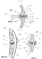
- FIG. 5 On the figure 5 is shown a portion of an oscillator balance 101 according to a second embodiment of the invention.
- Any reference designating below a part of the oscillator balance 101 identical or equivalent to a referenced part of the oscillator balance 1 is constructed by increasing by 100 the reference identifying this part on the oscillator balance 1.
- the references of the first part 103, of the second part 104, of the portions forming a spring 111 and of the ribs 135 of the oscillator balance 101 are made in particular the references of the first part 103, of the second part 104, of the portions forming a spring 111 and of the ribs 135 of the oscillator balance 101.
- the oscillator balance 101 differs from the oscillator balance 1 in that the circular arc band portions 33 do not exist there. In each retaining system 128, the two opposite clamping segments 131 are therefore not connected by a portion of band 33 in the form of an arc of a circle.
- an oscillator balance 201 according to a second embodiment of the invention.
- this oscillator balance 201 what distinguishes it from the oscillator balance 1.
- any reference designating hereinafter a part of the oscillator balance 201 identical or equivalent to a referenced part of the oscillator balance 1 is constructed by increasing by 200 the reference marking this part on the oscillator balance 1.
- the references of the adjustment weights 202, of the first part 203, of the second part 204, portions of circular arc strip 233 and the ribs 235 of the oscillator balance 201 are constructed in particular.
- each restraint system 228 is located equidistant from two consecutive arms 208.
- each connecting segment 209 comprises two portions forming a spring 211 of a retaining system 228 and a portion of strip in an arc of a circle 233 connecting these two portions forming a spring 211 to one another, as we can see at the figure 7 .
- FIG 8 shown is a portion of an oscillator balance 301 according to a fourth embodiment of the invention.
- Any reference designating hereinafter a part of the oscillator balance 301 identical or equivalent to a referenced part of the oscillator balance 201 is constructed by increasing by 100 the reference identifying this part on the oscillator balance 201. In this way are constructed in particular the references of each adjustment weight 302, of the first part 303, of the second part 304 and of the ribs 335 of the oscillator balance 301.
- the oscillator balance 301 differs from the oscillator balance 201 in that the circular arc strip portions 233 do not exist there. In each retaining system 328, the two portions forming a spring 311 are therefore not connected by a portion of strip in the form of an arc of a circle 233.
- FIG 9 On the figure 9 is shown a portion of an oscillator balance 401 according to a fifth embodiment of the invention.
- oscillator balance 401 according to a fifth embodiment of the invention.
- any reference hereinafter designating a part of the oscillator balance identical or equivalent to a part referenced balance of oscillator 1 is constructed by increasing by 400 the reference marking this part on the balance of oscillator 1. In this way the references of the first part 403 and of the second part 404 of the oscillator balance 401 are made in particular.
- Each guide wall hole 415 is threaded such that its wall can engage with a thread 425 on the flyweight rod 420 of an adjustment flyweight 402, in addition to being able to axially guide this flyweight rod 420.
- the thread 425 is on a threaded segment 424 of the flyweight shank 420, which further includes a prismatic segment 440 spaced from the head 421.
- the prismatic segment 440 comprises side panels 441 which follow one another in a closed loop.
- Each of the spring portions 411 of a retention system 428 consists of one of two flexible blades extending opposite each other from the distal end of an arm 408.
- each weight 402 is screwed into the guide wall hole 415 of a retaining system 428, the spring portions of which 411 clamp together the prismatic segment 440 of this adjustment weight 402.
- each guide wall hole 415 forms a relief pattern having the same function as two successions of mutually parallel ribs belonging to the same retaining system 28 of the oscillator balance 1.
- any reference hereinafter designating a part of the oscillator balance 501 which is identical or equivalent to a part referenced of the oscillator balance 401 is constructed by increasing by one hundred the reference marking this part on the oscillator balance 401. In this way are constructed in particular the references of each adjustment weight 502, of each threaded segment 524, of each segment prism 540, sides 541, the first part 503 and the second part 504 of the oscillator balance 501.
- Each retainer system 528 is located at the middle part of a connecting segment 509. At its middle part, each connecting segment 509 approaches the pivot axis yy 'of the oscillator balance 501 and carries two portions forming a spring 511 of a retaining system 528.
- an oscillator balance 601 is shown a portion of an oscillator balance 601 according to a seventh embodiment of the invention.
- any reference hereinafter designating a part of the oscillator balance 601 which is identical or equivalent to a part referenced of the oscillator balance 1 is constructed by increasing by six cents the reference marking this part on the oscillator balance 1.
- the references of each adjustment weight 602, of each retaining system 628, of the first part 603, the second part 604 and the ribs 635 of the oscillator balance 501 are constructed by increasing by six cents the reference marking this part on the oscillator balance 1.
- Each spring portion 611 includes a planar segment 630 connecting to a connecting segment 609.
- Each spring portion 611 further includes an elbow 632 and a flat clamping segment 631, which the elbow 632 connects to segment 630. opposite the elbow 632 connecting it to a segment 630, each clamping segment 631 connects to an arm 608. The two ends of a portion forming a spring 611 are thus immobilized.
- an oscillator balance 701 according to an eighth embodiment of the invention.
- any reference hereinafter designating a part of the oscillator balance 701 identical or equivalent to a part referenced of the oscillator balance 601 is constructed by increasing by one hundred the reference marking this part on the oscillator balance 601. In this way are constructed in particular the references of each adjustment weight 702, of the first part 703 and of the second part 704 of oscillator arm 701.
- Each retainer 728 is located at the middle portion of a connecting segment 709. At its middle portion, each connecting segment 709 approaches the pivot axis yy 'of the oscillator beam 701 and carries the two spring portions 711 of a retainer system 728.
- any reference hereinafter designating a part of the oscillator balance 801 which is identical or equivalent to a part referenced of the oscillator balance 401 is constructed by increasing by four cents the reference marking this part on the oscillator balance 401. In this way are constructed in particular the references of each adjustment weight 802, of the first part 803 and of the second part 804 of the oscillator balance 801.
- the flyweight rod 820 of each adjustment flyweight 802 has no prismatic segment 440.
- Each spring portion 811 of a retainer system 828 is carried by a connecting segment 809, from which it extends in a cutting plane. the axis of the guide wall hole 815 of this retainer 828.
- a flyweight rod 820 When screwed, a flyweight rod 820 is not clamped between two spring portions 811.
- a flyweight rod 820 pushes the two spring portions 811 of a retaining system 828 and elastically bends them. In reaction, these two portions forming a spring 811 together urge the weight rod 820 outwardly, keeping them bent.
- the thread 825 of the outwardly biased weight rod 820 is tightened to the thread 850 in engagement therewith.
- any reference hereinafter designating a part of the oscillator balance 901 which is identical or equivalent to a part referenced of the oscillator balance 801 is constructed by increasing by one hundred the reference marking this part on the oscillator balance 801. In this way are constructed in particular the references of each adjustment weight 902, of the first part 903 and of the second part 904 of oscillator arm 901.
- Each retainer 928 is located at the middle portion of a connecting segment 909. At its middle portion, each connecting segment 909 approaches the pivot axis yy 'of the oscillator balance 901 and carries the two portions forming a spring 911 of a retention system 928.
- an oscillator balance 1001 is shown a portion of an oscillator balance 1001 according to an eleventh embodiment of the invention.
- any reference hereinafter designating a part of the oscillator balance 1001 which is identical or equivalent to a part referenced of the oscillator balance 501 is constructed by increasing by five cents the reference marking this part on the oscillator balance 501.
- Each adjustment weight 1002 does not have an external head and does not protrude outside the second part 1004. Each adjustment weight 1002 is screwed from the inside into the second part 1004.
- Each connecting segment 1009 is interrupted in its middle and thus divided into two portions, each of which forms one of the two portions forming a spring 1011 of the same retaining system 1028 and one of two jaws 1060 directed towards one another. 'other. Each portion forming a spring 1011 is bent several times and is extended by one of the jaws 1060.
- the prismatic segment 1040 of each adjusting weight 1002 is clamped between the end faces of two free ends, each of which is the free end of one of the two jaws 1060 of a retainer 1028.
- the invention is not limited to the embodiments described above.
- the number of systems for retaining the adjustment weights may be different from four without departing from the scope of the invention.
- the same may apply to the number of adjustment weights and the number of arms of the oscillator balance, still without departing from the scope of the invention.
- the rim may not be circular over its entire length.
- the rim may locally approach the hub so as to delimit lateral recesses where the heads of the weights are located, without protruding from the largest outside diameter of the rim.
Landscapes
- Physics & Mathematics (AREA)
- General Physics & Mathematics (AREA)
- Springs (AREA)
- Transmission Devices (AREA)
Claims (17)
- Oszillatorunruh für ein Uhrwerk, umfassend einen Radkranz oder Rand (13), eine Vielzahl von Systemen (28 ; 128 ; 228 ; 328 ; 428 ; 528 ; 628 ; 728 ; 828 ; 928 ; 1028), um entlang des Radkranzes (13) angeordnete Einstellgewichtchen (2 ; 202 ; 302 ; 402 ; 502 ; 602 ; 702 ; 802 ; 902 ; 1002) zu halten, sowie einen ersten Monoblockteil (3 ; 103 ; 203 ; 303 ; 403 ; 503 ; 603 ; 703 ; 803 ; 903 ; 1003), welcher einen Hub (5) definiert, ausgebildet um auf eine Drehachse geschraubt zu werden, wobei zumindest ein erstes Rückhaltesystem (28 ; 128 ; 228 ; 328 ; 428 ; 528 ; 628 ; 728 ; 828 ; 928 ; 1028) der Rückhaltesysteme umfasst:- Eine Führungswandöffnung (15 ; 415 ; 815), welche zumindest einen Abschnitt einer Durchführung für eine Gewichtchenstange (20 ; 420 ; 820) bildet und welche in dem Radkranz (13) angeordnet ist,- Zumindest ein Reliefstruktur (35 ; 135 ; 235 ; 450 ; 635 ; 850), welche zumindest teilweise die Durchführung für die Gewichtchenstange (20 ; 420 ; 820) begrenzt und welche mit einem Gewinde (25 ; 425 ; 825) an der Gewichtchenstange (20 ; 420 ; 820) in Schraubverbindung stehen kann, wenn die Gewichtchenstange (20 ; 420 ; 820) in die Führungswandöffnung (15 ; 415 ; 815) eingeführt ist,- Zumindest einen Abschnitt, welcher eine Feder (11 ; 111 ; 211 ; 311 ; 411 ; 511 ; 611 ; 711 ; 811 ; 911 ; 1011) bildet, derart positioniert, dass eine elastische Verformung an dem eine Feder bildenden Abschnitt (11 ; 111 ; 211 ; 311 ; 411 ; 511 ; 611 ; 711 ; 811 ; 911 ; 1011) auftritt, wenn die Gewichtchenstange (20 ; 420 ; 820) in das erste Rückhaltesystem (28 ; 128 ; 228 ; 328 ; 428 ; 528 ; 628 ; 728 ; 828 ; 928 ; 1028) geschraubt ist und begleitet ist von einem Anziehen, welches ein zu überwindendes Bremsen erzeugt, um den Grad zu ändern, in dem die Gewichtchenstange (20 ; 420 ; 820) in das erste Rückhaltesystem (28 ; 128 ; 228 ; 328 ; 428 ; 528 ; 628 ; 728 ; 828 ; 928 ; 1028) geschraubt ist,dadurch gekennzeichnet, dass ein zweiter Teil (4 ; 104 ; 204 ; 304 ; 404 ; 504 ; 604 ; 704 ; 804 ; 904 ; 1004), welcher an dem ersten Teil (3 ; 103 ; 203 ; 303 ; 403 ; 503 ; 603 ; 703 ; 803 ; 903 ; 1003) befestigt ist, den Radkranz (13) definiert, wobei der erste Teil (3 ; 103 ; 203 ; 303 ; 403 ; 503 ; 603 ; 703 ; 803 ; 903 ; 1003) den eine Feder bildenden Abschnitt (11 ; 111 ; 211 ; 311 ; 411 ; 511 ; 611 ; 711 ; 811 ; 911 ; 1011) des ersten Rückhaltesystems (28 ; 128 ; 228 ; 328 ; 428 ; 528 ; 628 ; 728 ; 828 ; 928 ; 1028) definiert.
- Oszillatorunruh nach Anspruch 1,dadurch gekennzeichnet, dass der erste Teil (3 ; 103 ; 203 ; 303 ; 403 ; 503 ; 603 ; 703 ; 803 ; 903 ; 1003) ein elektrogeformter Teil ist.
- Oszillatorunruh nach Anspruch 1 oder 2, dadurch gekennzeichnet, dass die Führungswandöffnung (15 ; 415 ; 815) eine mechanisch gebohrte Öffnung ist.
- Oszillatorunruh nach einem der vorhergehenden Ansprüche, dadurch gekennzeichnet, dass der eine Feder bildende Abschnitt (11 ; 111 ; 211 ; 311 ; 411 ; 511 ; 611 ; 711 ; 1011) ein erster eine Feder bildender Abschnitt (11 ; 111 ; 211 ; 311 ; 411 ; 511 ; 611 ; 711 ; 1011) des ersten Rückhaltesystems (28 ; 128 ; 228 ; 328 ; 428 ; 528 ; 628 ; 728 ; 1028) ist, welche einen zweiten eine Feder bildenden Abschnitt (11 ; 111 ; 211 ; 311 ; 411 ; 511 ; 611 ; 711 ; 1011) aufweist, wobei der erste und der zweite eine Feder bildende Abschnitt (11 ; 111 ; 211 ; 311 ; 411 ; 511 ; 611 ; 711 ; 1011) derart angeordnet sind, dass jeder anfänglich zwei im Wesentlichen entgegengesetzte Komponenten des ein Bremsen erzeugenden Anziehens ist und derart, dass diese zwei Komponenten des ein Bremsen erzeugenden Anziehens eine Gewichtchenstange (20 ; 420) zwischen ihnen einklemmt, wenn eine derartige Gewichtchenstange (20 ; 420) in das erste Rückhaltesystem (28 ; 128 ; 228 ; 328 ; 428 ; 528 ; 628 ; 728 ; 1028) geschraubt ist.
- Oszillatorunruh nach einem der vorhergehenden Ansprüche, dadurch gekennzeichnet, dass die Reliefstruktur zumindest eine Reihe von zueinander parallelen Rippen (35 ; 135 ; 235) umfasst, getragen von dem ersten Teil (3 ; 103 ; 203 ; 303 ; 603 ; 703).
- Oszillatorunruh nach Anspruch 5, dadurch gekennzeichnet, dass der eine Feder bildende Abschnitt (11 ; 111 ; 211 ; 311 ; 611 ; 711) ein erster eine Feder bildender Abschnitt (11 ; 111 ; 211 ; 311 ; 611 ; 711) des ersten Rückhaltesystems (28 ; 128 ; 228 ; 328 ; 628 ; 728) ist, welche einen zweiten eine Feder bildenden Abschnitt (11 ; 111 ; 211 ; 311 ; 611 ; 711) umfasst, wobei der erste und der zweite eine Feder bildende Abschnitt (11 ; 111 ; 211 ; 311 ; 611 ; 711) derart angeordnet sind, dass jeder anfänglich entgegengesetzte Komponenten des das Bremsen erzeugende Anziehens ist und derart, dass jede der zwei Komponenten das das Bremsen erzeugende Anziehen über eine erste und zweite gegenüberliegende Fläche aufbringt, um zwischen sich eine Gewichtchenstange (20) zumindest an einem Bereich seiner Länge zu klemmen, wenn eine solche Gewichtchenstange (20) in das erste Rückhaltesystem (28 ; 128 ; 228 ; 328 ; 628 ; 728) geschraubt ist, wobei die erste Fläche eine Reihe von zueinander parallelen Rippen (35 ; 135 ; 235) trägt.
- Oszillatorunruh nach einem der vorhergehenden Ansprüche, dadurch gekennzeichnet, dass die Reliefstruktur erste und zweite Reihen von Rippen (35 ; 135 ; 235) enthält, parallel zueinander, getragen von dem ersten Teil (3 ; 103 ; 203 ; 303 ; 603 ; 703), wobei die ersten Reihen an zueinander parallelen Rippen (35 ; 135 ; 235) von einer zu einer die zweiten Reihen von zueinander parallelen Rippen (35 ; 135 ; 235) entgegengesetzten Fläche getragen ist.
- Oszillatorunruh nach Ansprüchen 6 und 7, dadurch gekennzeichnet, dass die erste Fläche die Fläche ist, welche die ersten Reihen von zueinander parallelen Rippen (35 ; 135 ; 235) trägt, wobei die zweite Fläche die Fläche ist, welche die zweiten Reihen von zueinander parallelen Rippen (35 ; 135 ; 235) trägt.
- Oszillatorunruh nach einem der vorhergehenden Ansprüche, dadurch gekennzeichnet, dass die Reliefstruktur eine Gewinde (450 ; 850) aufweist, welches in der Führungswandöffnung (415 ; 815) angeordnet ist.
- Oszillatorunruh nach einem der vorhergehenden Ansprüche, dadurch gekennzeichnet, dass sie eine Vielzahl von Einstellgewichtchen (2 ; 202 ; 302 ; 402 ; 502 ; 602 ; 702 ; 802 ; 902 ; 1002) aufweist, wobei ein erstes Einstellgewichtchen (2 ; 202 ; 302 ; 402 ; 502 ; 602 ; 702 ; 802 ; 902 ; 1002) dieser Einstellgewichtchen eine Gewichtchenstange (20 ; 420 ; 820) hat, welche in die Führungswandöffnung (15 ; 415 ; 815) eingeführt ist und welche dort in seiner Schraubrichtung (V) geführt ist, ein Gewinde (25 ; 425 ; 825), welches zumindest an einem Längenabschnitt der Gewichtchenstange (20 ; 420 ; 820) des ersten Einstellgewichtchens (2 ; 202 ; 302 ; 402 ; 502 ; 602 ; 702 ; 802 ; 902 ; 1002) vorgesehen ist, um in Schraubverbindung mit der Reliefstruktur (35 ; 135 ; 235 ; 450 ; 635 ; 850) gebracht zu werden, wenn der eine Schraube bildende Abschnitt (11 ; 111 ; 211 ; 311 ; 411 ; 511 ; 611 ; 711 ; 811 ; 911 ; 1011) einer elastischen Verformung unterworfen ist zu Beginn des Anziehens, welches eine Klemmung ist, stattfindend an dem ersten Einstellgewichtchen (2 ; 202 ; 302 ; 402 ; 502 ; 602 ; 702 ; 802 ; 902 ; 1002) derart, dass durch das Klemmen erzeugte Bremsen ein Bremsen ist, welches überwunden wird, um den Grad zu ändern, in dem das erste Einstellgewichtchen (2 ; 202 ; 302 ; 402 ; 502 ; 602 ; 702 ; 802 ; 902 ; 1002) eingeschraubt ist.
- Oszillatorunruh nach Anspruch 10, dadurch gekennzeichnet, dass ein Segment der Gewichtchenstange (20 ; 420 ; 820) des ersten Gewichtchens eine laterale Fläche umfasst, welche ringförmige Serien von Seiten (441 ; 541) umfasst, wobei der eine Feder bildende Abschnitt (411 ; 511 ; 1011) elastisch eine Fläche eines Abschnitts des ersten Teils (403 ; 503 ; 1003) gegen eine der Seiten (441 ; 541) zurückzieht.
- Oszillatorunruh nach einem der vorhergehenden Ansprüche, dadurch gekennzeichnet, dass der erste Teil (3 ; 103 ; 203 ; 303 ; 403 ; 503 ; 603 ; 703 ; 803 ; 903 ; 1003) eine Vielzahl von Armen (8 ; 208 ; 408 ; 608) und eine Vielzahl von Verbindungssegmenten (9 ; 209 ; 509 ; 609 ; 709 ; 809 ; 909 ; 1009) umfasst, wobei die Arme (8 ; 208 ; 408 ; 608) mit dem Hub (5) verbunden sind, wobei die Verbindungssegmente (9 ; 209 ; 509 ; 609 ; 709 ; 809 ; 909 ; 1009) die Arme (8 ; 208 ; 408 ; 608) miteinander in einem Abstand zum Hub (5) verbinden.
- Oszillatorunruh nach Anspruch 12, dadurch gekennzeichnet, dass der erste Teil (3 ; 103 ; 203 ; 303 ; 403 ; 503 ; 603 ; 703 ; 803 ; 903 ; 1003) an den Verbindungssegmenten (9 ; 209 ; 509 ; 609 ; 709 ; 809 ; 909 ; 1009) befestigt ist.
- Verfahren zur Herstellung einer Oszillatorunruh für ein Uhrwerk, umfassend die Schritte, wobei:a) Erzeugen in einem Stück einen ersten Teil (3 ; 103 ; 203 ; 303 ; 403 ; 503 ; 603 ; 703 ; 803 ; 903 ; 1003), welcher zumindest einen eine Feder bildenden Abschnitt (11 ; 111 ; 211 ; 311 ; 411 ; 511 ; 611 ; 711 ; 811 ; 911 ; 1011) definiert und einen Hub (5), welcher eingerichtet ist, um auf einer Drehwelle geschraubt zu werden;b) Erzeugen eines zweiten Teils (4 ; 104 ; 204 ; 304 ; 404 ; 504 ; 604 ; 704 ; 804 ; 904 ; 1004), welcher einen Radkranz oder Rand (13) definiert, in dem sich zumindest eine Führungswandöffnung (15 ; 415 ; 815) befindet; undc) Fixieren der ersten und zweiten Teile miteinander derart, dass ein Rückhaltesystem (28 ; 128 ; 228 ; 328 ; 428 ; 528 ; 628 ; 728 ; 828 ; 928 ; 1028) gebildet ist, welches umfasst :- Die Führungswandöffnung (15 ; 415 ; 815), welche zumindest einen Abschnitt einer Durchführung für eine Gewichtchenstange (20 ; 420 ; 820) bildet,- Zumindest eine Reliefstruktur (35 ; 135 ; 235 ; 450 ; 635 ; 850), welche zumindest teilweise die Durchführung für die Gewichtchenstange (20 ; 420 ; 820) begrenzt und welche in Schraubverbindung mit einem Gewinde (25 ; 425 ; 825) an der Gewichtchenstange (20 ; 420 ; 820) bringbar ist, wenn die Gewichtchenstange (20 ; 420 ; 820) in die Führungswandöffnung (15 ; 415 ; 815) eingeführt ist,- Der eine Feder bildende Abschnitt (11 ; 111 ; 211 ; 311 ; 411 ; 511 ; 611 ; 711 ; 811 ; 911 ; 1011), welcher derart positionierbar ist, dass eine elastische Verformung des eine Feder bildenden Abschnitts (11 ; 111 ; 211 ; 311 ; 411 ; 511 ; 611 ; 711 ; 811 ; 911 ; 1011) erfolgt, wenn die Gewichtchenstange (20 ; 420 ; 820) in das Rückhaltesystem (28 ; 128 ; 228 ; 328 ; 428 ; 528 ; 628 ; 728 ; 828 ; 928 ; 1028) geschraubt ist und begleitet ist von einem Anziehen, welches ein Bremsen erzeugt, das zu überwinden ist, um den Grad zu ändern, mit dem die Gewichtchenstange (20 ; 420 ; 820) in das Rückhaltesystem (28 ; 128 ; 228 ; 328 ; 428 ; 528 ; 628 ; 728 ; 828 ; 928 ; 1028) geschraubt ist.
- Verfahren zur Herstellung einer Oszillatorunruh nach Anspruch 14, dadurch gekennzeichnet, dass in Schritt a), der erste Teil (3 ; 103 ; 203 ; 303 ; 403 ; 503 ; 603 ; 703 ; 803 ; 903 ; 1003) durch Implementieren des LIGA Prozesses erzeugt wird.
- Verfahren zur Herstellung einer Oszillatorunruh nach Anspruch 14 und 15, dadurch gekennzeichnet, dass in Schritt b) die Führungswandöffnung (15 ; 415 ; 815) in den zweiten Teil (4 ; 104 ; 204 ; 304 ; 404 ; 504 ; 604 ; 704 ; 804 ; 904 ; 1004) mechanisch gebohrt ist.
- Verfahren zur Herstellung einer Oszillatorunruh nach einem der Ansprüche 14 bis 16, dadurch gekennzeichnet, dass der erste Teil (3 ; 103 ; 203 ; 303 ; 403 ; 503 ; 603 ; 703 ; 803 ; 903 ; 1003) erzeugt wird durch Implementieren eines ersten Typs eines Verfahrens, welches sich von einem zweiten Typ eines Verfahrens unterscheidet, welches implementiert ist, um den zweiten Teil (4 ; 104 ; 204 ; 304 ; 404 ; 504 ; 604 ; 704 ; 804 ; 904 ; 1004) zu erzeugen.
Priority Applications (1)
| Application Number | Priority Date | Filing Date | Title |
|---|---|---|---|
| EP18192997.7A EP3620864B1 (de) | 2018-09-06 | 2018-09-06 | Oszillator-unruh für uhrwerk, und herstellungsverfahren einer solchen unruh |
Applications Claiming Priority (1)
| Application Number | Priority Date | Filing Date | Title |
|---|---|---|---|
| EP18192997.7A EP3620864B1 (de) | 2018-09-06 | 2018-09-06 | Oszillator-unruh für uhrwerk, und herstellungsverfahren einer solchen unruh |
Publications (2)
| Publication Number | Publication Date |
|---|---|
| EP3620864A1 EP3620864A1 (de) | 2020-03-11 |
| EP3620864B1 true EP3620864B1 (de) | 2021-01-20 |
Family
ID=63524186
Family Applications (1)
| Application Number | Title | Priority Date | Filing Date |
|---|---|---|---|
| EP18192997.7A Active EP3620864B1 (de) | 2018-09-06 | 2018-09-06 | Oszillator-unruh für uhrwerk, und herstellungsverfahren einer solchen unruh |
Country Status (1)
| Country | Link |
|---|---|
| EP (1) | EP3620864B1 (de) |
Family Cites Families (2)
| Publication number | Priority date | Publication date | Assignee | Title |
|---|---|---|---|---|
| FR936423A (fr) | 1946-12-03 | 1948-07-20 | Balancier de pièce d'horlogerie à moment d'inertie réglable | |
| CH704131B1 (fr) | 2010-11-25 | 2015-06-15 | Complitime Sa | Balancier pour pièce d’horlogerie. |
-
2018
- 2018-09-06 EP EP18192997.7A patent/EP3620864B1/de active Active
Also Published As
| Publication number | Publication date |
|---|---|
| EP3620864A1 (de) | 2020-03-11 |
Similar Documents
| Publication | Publication Date | Title |
|---|---|---|
| EP2410386B1 (de) | Unruh mit Trägheitsregulierung mit Einsatzteil | |
| EP2407831B1 (de) | Spirale für Unruh-Oszillator einer Uhr, und ihr Herstellungsverfahren | |
| EP3623876B1 (de) | Spiralrolle mit nicht kreisförmiger öffnung | |
| EP1584994B1 (de) | Spiralrolle ohne Deformation des Fixierungsradius der Spiralfeder und Herstellungsverfahren derartige Spiralrolle | |
| EP2674817B1 (de) | Verfahren zur Herstellung eines Uhrfederhauswelle | |
| EP4009115A1 (de) | Spiralfeder für resonatormechanismus eines uhrwerks, der mit mitteln zum ausgleichen der starrheit ausgestattet ist | |
| EP2952971B1 (de) | Anker für Hemmungsmechanismus eines Uhrwerks | |
| EP1850193B1 (de) | Verfahren zur Einpressung eines Teils in ein anderes Teil | |
| EP1445668B1 (de) | Schwungmasse | |
| WO2009115519A1 (fr) | Organe de pivotement | |
| EP1837719A1 (de) | Unruh für Uhrwerk | |
| EP3812843B1 (de) | Flexible führung und gesamtheit von übereinander angeordneten flexiblen führungen für sich drehenden resonatormechanismus, insbesondere für uhrwerk | |
| EP4194964B1 (de) | Unruh mit trägheitsregulierung | |
| CH705087B1 (fr) | Pièce d'horlogerie. | |
| EP3430479B1 (de) | Vorrichtung für eine uhr, uhrwerk und uhr mit solch einer vorrichtung | |
| EP2230571A1 (de) | Radialverschlusssystem für Uhrwerkskomponente | |
| WO2021121707A1 (fr) | Mecanisme d'affichage d'horlogerie | |
| EP2506093B1 (de) | Unruh für Uhrwerk | |
| EP3183618B1 (de) | Zeiger einer armbanduhr | |
| EP3620864A1 (de) | Oszillator-unruh für uhrwerk, und herstellungsverfahren einer solchen unruh | |
| EP3499318B1 (de) | Schwingsystem für armbanduhr | |
| EP3907563B1 (de) | Uhrwerkmechanismus, das ein schwenkorgan umfasst | |
| EP3839661B1 (de) | Stossdämpfervorrichtung mit winkelverriegelung | |
| CH712197A2 (fr) | Système à friction pour mouvement d'horlogerie et son procédé d'assemblage. | |
| EP3273311A1 (de) | Anzeigevorrichtung |
Legal Events
| Date | Code | Title | Description |
|---|---|---|---|
| PUAI | Public reference made under article 153(3) epc to a published international application that has entered the european phase |
Free format text: ORIGINAL CODE: 0009012 |
|
| STAA | Information on the status of an ep patent application or granted ep patent |
Free format text: STATUS: THE APPLICATION HAS BEEN PUBLISHED |
|
| AK | Designated contracting states |
Kind code of ref document: A1 Designated state(s): AL AT BE BG CH CY CZ DE DK EE ES FI FR GB GR HR HU IE IS IT LI LT LU LV MC MK MT NL NO PL PT RO RS SE SI SK SM TR |
|
| AX | Request for extension of the european patent |
Extension state: BA ME |
|
| STAA | Information on the status of an ep patent application or granted ep patent |
Free format text: STATUS: REQUEST FOR EXAMINATION WAS MADE |
|
| 17P | Request for examination filed |
Effective date: 20200421 |
|
| RBV | Designated contracting states (corrected) |
Designated state(s): AL AT BE BG CH CY CZ DE DK EE ES FI FR GB GR HR HU IE IS IT LI LT LU LV MC MK MT NL NO PL PT RO RS SE SI SK SM TR |
|
| RIC1 | Information provided on ipc code assigned before grant |
Ipc: G04B 18/00 20060101AFI20200805BHEP |
|
| GRAP | Despatch of communication of intention to grant a patent |
Free format text: ORIGINAL CODE: EPIDOSNIGR1 |
|
| STAA | Information on the status of an ep patent application or granted ep patent |
Free format text: STATUS: GRANT OF PATENT IS INTENDED |
|
| INTG | Intention to grant announced |
Effective date: 20201020 |
|
| GRAS | Grant fee paid |
Free format text: ORIGINAL CODE: EPIDOSNIGR3 |
|
| GRAA | (expected) grant |
Free format text: ORIGINAL CODE: 0009210 |
|
| STAA | Information on the status of an ep patent application or granted ep patent |
Free format text: STATUS: THE PATENT HAS BEEN GRANTED |
|
| AK | Designated contracting states |
Kind code of ref document: B1 Designated state(s): AL AT BE BG CH CY CZ DE DK EE ES FI FR GB GR HR HU IE IS IT LI LT LU LV MC MK MT NL NO PL PT RO RS SE SI SK SM TR |
|
| REG | Reference to a national code |
Ref country code: GB Ref legal event code: FG4D Free format text: NOT ENGLISH |
|
| REG | Reference to a national code |
Ref country code: CH Ref legal event code: EP |
|
| REG | Reference to a national code |
Ref country code: DE Ref legal event code: R096 Ref document number: 602018011992 Country of ref document: DE |
|
| REG | Reference to a national code |
Ref country code: AT Ref legal event code: REF Ref document number: 1356947 Country of ref document: AT Kind code of ref document: T Effective date: 20210215 |
|
| REG | Reference to a national code |
Ref country code: IE Ref legal event code: FG4D Free format text: LANGUAGE OF EP DOCUMENT: FRENCH |
|
| REG | Reference to a national code |
Ref country code: CH Ref legal event code: NV Representative=s name: BOVARD AG PATENT- UND MARKENANWAELTE, CH |
|
| REG | Reference to a national code |
Ref country code: NL Ref legal event code: MP Effective date: 20210120 |
|
| REG | Reference to a national code |
Ref country code: LT Ref legal event code: MG9D |
|
| REG | Reference to a national code |
Ref country code: AT Ref legal event code: MK05 Ref document number: 1356947 Country of ref document: AT Kind code of ref document: T Effective date: 20210120 |
|
| PG25 | Lapsed in a contracting state [announced via postgrant information from national office to epo] |
Ref country code: HR Free format text: LAPSE BECAUSE OF FAILURE TO SUBMIT A TRANSLATION OF THE DESCRIPTION OR TO PAY THE FEE WITHIN THE PRESCRIBED TIME-LIMIT Effective date: 20210120 Ref country code: GR Free format text: LAPSE BECAUSE OF FAILURE TO SUBMIT A TRANSLATION OF THE DESCRIPTION OR TO PAY THE FEE WITHIN THE PRESCRIBED TIME-LIMIT Effective date: 20210421 Ref country code: FI Free format text: LAPSE BECAUSE OF FAILURE TO SUBMIT A TRANSLATION OF THE DESCRIPTION OR TO PAY THE FEE WITHIN THE PRESCRIBED TIME-LIMIT Effective date: 20210120 Ref country code: BG Free format text: LAPSE BECAUSE OF FAILURE TO SUBMIT A TRANSLATION OF THE DESCRIPTION OR TO PAY THE FEE WITHIN THE PRESCRIBED TIME-LIMIT Effective date: 20210420 Ref country code: LT Free format text: LAPSE BECAUSE OF FAILURE TO SUBMIT A TRANSLATION OF THE DESCRIPTION OR TO PAY THE FEE WITHIN THE PRESCRIBED TIME-LIMIT Effective date: 20210120 Ref country code: NO Free format text: LAPSE BECAUSE OF FAILURE TO SUBMIT A TRANSLATION OF THE DESCRIPTION OR TO PAY THE FEE WITHIN THE PRESCRIBED TIME-LIMIT Effective date: 20210420 Ref country code: PT Free format text: LAPSE BECAUSE OF FAILURE TO SUBMIT A TRANSLATION OF THE DESCRIPTION OR TO PAY THE FEE WITHIN THE PRESCRIBED TIME-LIMIT Effective date: 20210520 |
|
| PG25 | Lapsed in a contracting state [announced via postgrant information from national office to epo] |
Ref country code: AT Free format text: LAPSE BECAUSE OF FAILURE TO SUBMIT A TRANSLATION OF THE DESCRIPTION OR TO PAY THE FEE WITHIN THE PRESCRIBED TIME-LIMIT Effective date: 20210120 Ref country code: RS Free format text: LAPSE BECAUSE OF FAILURE TO SUBMIT A TRANSLATION OF THE DESCRIPTION OR TO PAY THE FEE WITHIN THE PRESCRIBED TIME-LIMIT Effective date: 20210120 Ref country code: PL Free format text: LAPSE BECAUSE OF FAILURE TO SUBMIT A TRANSLATION OF THE DESCRIPTION OR TO PAY THE FEE WITHIN THE PRESCRIBED TIME-LIMIT Effective date: 20210120 Ref country code: LV Free format text: LAPSE BECAUSE OF FAILURE TO SUBMIT A TRANSLATION OF THE DESCRIPTION OR TO PAY THE FEE WITHIN THE PRESCRIBED TIME-LIMIT Effective date: 20210120 Ref country code: SE Free format text: LAPSE BECAUSE OF FAILURE TO SUBMIT A TRANSLATION OF THE DESCRIPTION OR TO PAY THE FEE WITHIN THE PRESCRIBED TIME-LIMIT Effective date: 20210120 |
|
| PG25 | Lapsed in a contracting state [announced via postgrant information from national office to epo] |
Ref country code: IS Free format text: LAPSE BECAUSE OF FAILURE TO SUBMIT A TRANSLATION OF THE DESCRIPTION OR TO PAY THE FEE WITHIN THE PRESCRIBED TIME-LIMIT Effective date: 20210520 |
|
| REG | Reference to a national code |
Ref country code: DE Ref legal event code: R097 Ref document number: 602018011992 Country of ref document: DE |
|
| PG25 | Lapsed in a contracting state [announced via postgrant information from national office to epo] |
Ref country code: CZ Free format text: LAPSE BECAUSE OF FAILURE TO SUBMIT A TRANSLATION OF THE DESCRIPTION OR TO PAY THE FEE WITHIN THE PRESCRIBED TIME-LIMIT Effective date: 20210120 Ref country code: EE Free format text: LAPSE BECAUSE OF FAILURE TO SUBMIT A TRANSLATION OF THE DESCRIPTION OR TO PAY THE FEE WITHIN THE PRESCRIBED TIME-LIMIT Effective date: 20210120 Ref country code: SM Free format text: LAPSE BECAUSE OF FAILURE TO SUBMIT A TRANSLATION OF THE DESCRIPTION OR TO PAY THE FEE WITHIN THE PRESCRIBED TIME-LIMIT Effective date: 20210120 |
|
| PLBE | No opposition filed within time limit |
Free format text: ORIGINAL CODE: 0009261 |
|
| STAA | Information on the status of an ep patent application or granted ep patent |
Free format text: STATUS: NO OPPOSITION FILED WITHIN TIME LIMIT |
|
| PG25 | Lapsed in a contracting state [announced via postgrant information from national office to epo] |
Ref country code: RO Free format text: LAPSE BECAUSE OF FAILURE TO SUBMIT A TRANSLATION OF THE DESCRIPTION OR TO PAY THE FEE WITHIN THE PRESCRIBED TIME-LIMIT Effective date: 20210120 Ref country code: SK Free format text: LAPSE BECAUSE OF FAILURE TO SUBMIT A TRANSLATION OF THE DESCRIPTION OR TO PAY THE FEE WITHIN THE PRESCRIBED TIME-LIMIT Effective date: 20210120 Ref country code: DK Free format text: LAPSE BECAUSE OF FAILURE TO SUBMIT A TRANSLATION OF THE DESCRIPTION OR TO PAY THE FEE WITHIN THE PRESCRIBED TIME-LIMIT Effective date: 20210120 |
|
| 26N | No opposition filed |
Effective date: 20211021 |
|
| PG25 | Lapsed in a contracting state [announced via postgrant information from national office to epo] |
Ref country code: ES Free format text: LAPSE BECAUSE OF FAILURE TO SUBMIT A TRANSLATION OF THE DESCRIPTION OR TO PAY THE FEE WITHIN THE PRESCRIBED TIME-LIMIT Effective date: 20210120 Ref country code: AL Free format text: LAPSE BECAUSE OF FAILURE TO SUBMIT A TRANSLATION OF THE DESCRIPTION OR TO PAY THE FEE WITHIN THE PRESCRIBED TIME-LIMIT Effective date: 20210120 |
|
| PG25 | Lapsed in a contracting state [announced via postgrant information from national office to epo] |
Ref country code: SI Free format text: LAPSE BECAUSE OF FAILURE TO SUBMIT A TRANSLATION OF THE DESCRIPTION OR TO PAY THE FEE WITHIN THE PRESCRIBED TIME-LIMIT Effective date: 20210120 |
|
| REG | Reference to a national code |
Ref country code: DE Ref legal event code: R119 Ref document number: 602018011992 Country of ref document: DE |
|
| PG25 | Lapsed in a contracting state [announced via postgrant information from national office to epo] |
Ref country code: IT Free format text: LAPSE BECAUSE OF FAILURE TO SUBMIT A TRANSLATION OF THE DESCRIPTION OR TO PAY THE FEE WITHIN THE PRESCRIBED TIME-LIMIT Effective date: 20210120 |
|
| REG | Reference to a national code |
Ref country code: BE Ref legal event code: MM Effective date: 20210930 |
|
| PG25 | Lapsed in a contracting state [announced via postgrant information from national office to epo] |
Ref country code: IS Free format text: LAPSE BECAUSE OF FAILURE TO SUBMIT A TRANSLATION OF THE DESCRIPTION OR TO PAY THE FEE WITHIN THE PRESCRIBED TIME-LIMIT Effective date: 20210520 Ref country code: MC Free format text: LAPSE BECAUSE OF FAILURE TO SUBMIT A TRANSLATION OF THE DESCRIPTION OR TO PAY THE FEE WITHIN THE PRESCRIBED TIME-LIMIT Effective date: 20210120 |
|
| PG25 | Lapsed in a contracting state [announced via postgrant information from national office to epo] |
Ref country code: LU Free format text: LAPSE BECAUSE OF NON-PAYMENT OF DUE FEES Effective date: 20210906 Ref country code: FR Free format text: LAPSE BECAUSE OF NON-PAYMENT OF DUE FEES Effective date: 20210930 Ref country code: DE Free format text: LAPSE BECAUSE OF NON-PAYMENT OF DUE FEES Effective date: 20220401 Ref country code: BE Free format text: LAPSE BECAUSE OF NON-PAYMENT OF DUE FEES Effective date: 20210930 Ref country code: IE Free format text: LAPSE BECAUSE OF NON-PAYMENT OF DUE FEES Effective date: 20210906 |
|
| GBPC | Gb: european patent ceased through non-payment of renewal fee |
Effective date: 20220906 |
|
| PG25 | Lapsed in a contracting state [announced via postgrant information from national office to epo] |
Ref country code: NL Free format text: LAPSE BECAUSE OF NON-PAYMENT OF DUE FEES Effective date: 20210120 Ref country code: CY Free format text: LAPSE BECAUSE OF FAILURE TO SUBMIT A TRANSLATION OF THE DESCRIPTION OR TO PAY THE FEE WITHIN THE PRESCRIBED TIME-LIMIT Effective date: 20210120 |
|
| PG25 | Lapsed in a contracting state [announced via postgrant information from national office to epo] |
Ref country code: HU Free format text: LAPSE BECAUSE OF FAILURE TO SUBMIT A TRANSLATION OF THE DESCRIPTION OR TO PAY THE FEE WITHIN THE PRESCRIBED TIME-LIMIT; INVALID AB INITIO Effective date: 20180906 |
|
| PG25 | Lapsed in a contracting state [announced via postgrant information from national office to epo] |
Ref country code: GB Free format text: LAPSE BECAUSE OF NON-PAYMENT OF DUE FEES Effective date: 20220906 |
|
| PG25 | Lapsed in a contracting state [announced via postgrant information from national office to epo] |
Ref country code: MK Free format text: LAPSE BECAUSE OF FAILURE TO SUBMIT A TRANSLATION OF THE DESCRIPTION OR TO PAY THE FEE WITHIN THE PRESCRIBED TIME-LIMIT Effective date: 20210120 |
|
| PG25 | Lapsed in a contracting state [announced via postgrant information from national office to epo] |
Ref country code: MT Free format text: LAPSE BECAUSE OF FAILURE TO SUBMIT A TRANSLATION OF THE DESCRIPTION OR TO PAY THE FEE WITHIN THE PRESCRIBED TIME-LIMIT Effective date: 20210120 |
|
| REG | Reference to a national code |
Ref country code: CH Ref legal event code: U11 Free format text: ST27 STATUS EVENT CODE: U-0-0-U10-U11 (AS PROVIDED BY THE NATIONAL OFFICE) Effective date: 20251001 |
|
| PG25 | Lapsed in a contracting state [announced via postgrant information from national office to epo] |
Ref country code: TR Free format text: LAPSE BECAUSE OF FAILURE TO SUBMIT A TRANSLATION OF THE DESCRIPTION OR TO PAY THE FEE WITHIN THE PRESCRIBED TIME-LIMIT Effective date: 20210120 |
|
| PGFP | Annual fee paid to national office [announced via postgrant information from national office to epo] |
Ref country code: CH Payment date: 20251001 Year of fee payment: 8 |