EP3621485B1 - Befestigungsbeschlag für eine blende - Google Patents
Befestigungsbeschlag für eine blende Download PDFInfo
- Publication number
- EP3621485B1 EP3621485B1 EP18724522.0A EP18724522A EP3621485B1 EP 3621485 B1 EP3621485 B1 EP 3621485B1 EP 18724522 A EP18724522 A EP 18724522A EP 3621485 B1 EP3621485 B1 EP 3621485B1
- Authority
- EP
- European Patent Office
- Prior art keywords
- panel
- fitting
- locking means
- parts
- fastening
- Prior art date
- Legal status (The legal status is an assumption and is not a legal conclusion. Google has not performed a legal analysis and makes no representation as to the accuracy of the status listed.)
- Active
Links
Images


Classifications
-
- A—HUMAN NECESSITIES
- A47—FURNITURE; DOMESTIC ARTICLES OR APPLIANCES; COFFEE MILLS; SPICE MILLS; SUCTION CLEANERS IN GENERAL
- A47B—TABLES; DESKS; OFFICE FURNITURE; CABINETS; DRAWERS; GENERAL DETAILS OF FURNITURE
- A47B88/00—Drawers for tables, cabinets or like furniture; Guides for drawers
- A47B88/90—Constructional details of drawers
- A47B88/944—Drawers characterised by the front panel
- A47B88/95—Drawers characterised by the front panel characterised by connection means for the front panel
- A47B88/956—Drawers characterised by the front panel characterised by connection means for the front panel for enabling adjustment of the front panel
-
- A—HUMAN NECESSITIES
- A47—FURNITURE; DOMESTIC ARTICLES OR APPLIANCES; COFFEE MILLS; SPICE MILLS; SUCTION CLEANERS IN GENERAL
- A47B—TABLES; DESKS; OFFICE FURNITURE; CABINETS; DRAWERS; GENERAL DETAILS OF FURNITURE
- A47B88/00—Drawers for tables, cabinets or like furniture; Guides for drawers
- A47B88/90—Constructional details of drawers
- A47B88/941—Drawers being constructed from two or more parts
-
- A—HUMAN NECESSITIES
- A47—FURNITURE; DOMESTIC ARTICLES OR APPLIANCES; COFFEE MILLS; SPICE MILLS; SUCTION CLEANERS IN GENERAL
- A47B—TABLES; DESKS; OFFICE FURNITURE; CABINETS; DRAWERS; GENERAL DETAILS OF FURNITURE
- A47B88/00—Drawers for tables, cabinets or like furniture; Guides for drawers
- A47B88/90—Constructional details of drawers
- A47B88/944—Drawers characterised by the front panel
- A47B88/95—Drawers characterised by the front panel characterised by connection means for the front panel
- A47B2088/952—Drawers characterised by the front panel characterised by connection means for the front panel having two parts and using a screw
Definitions
- the invention relates to a fastening fitting for a panel on an open end face of a drawer according to the preamble of claim 1.
- Such a panel mounting bracket is through the DE 20 2014 002 229 U1 is known and has a panel which carries on its back two panel mounting parts aligned with the outer sides of the side walls of the drawer and the side walls of the drawer carry two fitting parts which receive the panel mounting parts, the panel mounting parts being able to be fixed in the fitting parts.
- the bezel attachment hardware and bezel mounting hardware have additional features, namely:
- the EP 0 323 822 teaches a drawer with pull-out fittings which has a front panel with brackets that can be adjusted in height relative to the frames of the drawer via eccentrics.
- the locking means according to the invention which are secured against opening by mere rotation, are not taught by this publication.
- the WO 2010/136228 A1 also teaches a drawer assembly having an eccentric for adjusting the alignment of the faceplate with respect to the frames, wherein connection between the faceplate and frame is provided by a clip system which engages a two-piece receptacle of the faceplate. A connection between the front fitting and the frame can be released by rotating the two arms of the clamp system in opposite directions. However, a translational movement of locking means for releasing a connection with a bolt is not disclosed.
- a panel attachment fitting in which the inclination of the panel can be adjusted by means of a part of a multi-part side panel fitting which accommodates a panel fitting and holds it in an unchangeable position relative to itself, with the part of the side panel fitting being opposite to another part of the side panel fitting, the is fixedly attached to the side wall, is relatively movable that an inclination adjustment of the panel is made possible.
- using the panel attachment fitting on tall drawers which may have more than one panel fitting on one side of the drawer and which attaches to the side panel fitting, while still easily adjusting the panel angle should be difficult.
- a visor attachment fitting in which a multi-part visor fitting has a part which is pivotable about a pivot point within the visor fitting relative to a perpendicular to the rear wall of the visor, the part being held in a fixed position in a side wall fitting and is held. Due to the pivotability of the part, an inclination adjustment of the panel is made possible. The mechanical stability of the fascia fitting appears prone to unintentional adjustment of the fascia due to the fixability of the tilt adjustment at the pivot point. This embodiment also does not appear to be suitable for use with tall drawers.
- TW I 548 371 B A substantially identical second embodiment of attachment of the panel fitting is also described.
- the adjusting body is designed as an eccentric bolt, and in which either means for adjusting the inclination comprise a fork of the panel assembly part which is directed towards the panel fitting part and which accommodates the eccentric bolt or in which the means for adjusting the inclination comprise an elongate baffle plate arranged vertically on the fascia fitting part, the eccentric bolt or one end of the baffle plate being able to be placed alternately on end contact surfaces of the fascia assembly part and an additional fascia assembly part arranged above it, and a second End of the guide plate is connected to the eccentric bolt.
- a fastening fitting which has means for adjusting the inclination and/or at least one guide section in which a locking means is movably mounted. Inclination adjustment and the features related to the guide section and its movable arrangement can therefore be realized independently of each other.
- locking means all those elements and means that are suitable for forming a connection with a counterpart on a drawer panel.
- the fixing means can be a catch hook.
- the panel mounting part has openings on the panel side, by means of which it can be connected to the panel, for example via screws or bolt connections that can be locked in place.
- the axis of the adjustment body and the pivoting axis of the panel run parallel.
- the panel can be pivoted by an angle of up to +/- 5 degrees.
- the eccentric bolts are preferably guided through a recess in the guide plate at one end and are mounted in the screen fitting part, with the guide plate having a part bent by 90° at its other end.
- the panel mounting part is vertically or horizontally adjustable relative to the panel fitting part.
- the visor assembly part is vertically adjustable relative to the visor fitting part by means of the adjusting body designed as an eccentric bolt.
- the cover assembly part can be adjusted horizontally relative to the cover fitting part by means of a screw connection.
- At least one release element is preferably provided for releasing the connection between the locking means and the panel mounting part on the panel fitting part.
- the panel fitting part particularly preferably has at least two locking means, with the individual locking means being releasable by means of separate release elements.
- a further advantageous embodiment of the invention allows a snap-in connection of the panel assembly part with the panel fitting part by means of a locking bolt mounted in the panel assembly part, which engages in a movable, spring-loaded and latchable fixing means of the panel fitting part by sliding horizontally into one another and via a release element a fold-out actuating part can be released against the spring force, with the locking means having a slotted part which, when released, is aligned with a horizontal slot of the fitting part, with the locking bolt being able to be pushed horizontally into both slots during the connection process and with the slot of the locking means being in the engaged state is rotated relative to the slot of the fitting and prevents the fan bolt from sliding out of the locking means.
- the fixing means can preferably be hook-shaped.
- the panel fitting part has angled areas that enable a simple connection to a side part of the drawer, the connection being secured by means of screws, rivets, snap-in or pressable bolts, etc. Provision is particularly preferably made for at least one release element for releasing the connection between the fixing means and the panel mounting part to be provided on the panel fitting part.
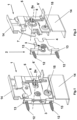
- a panel fitting part 1 for a drawer is shown, the view being directed towards the fastening side facing the side wall of the drawer.
- the panel fitting part 1 has angled areas 14 for easy connection to the side part of the drawer, with the connection being secured by means of screws, rivets, latchable or pressable bolts, etc.
- a panel assembly part 2 connected to the panel fitting part 1 is screwed to the back of the panel via bores 13 in the assembly part 2 and corresponding screws 12 or bolt connections that can be locked in place.
- a locking bolt 3 of the panel mounting part 2 connects it to the locking means 7 of the panel fitting part 1 at a predetermined distance from the back of the panel.
- the fascia of the drawer carries two such fascia mounting parts 2, connected to respective fascia fittings 1, at a distance adapted to the dimension of the outer sides of the two side walls of the open front of the drawer.
- the 1 also shows two legs of a fork 4 of the panel mounting part 2, which is directed towards the panel fitting part 1 and which encloses an adjusting body 5 designed as an eccentric bolt.
- an adjusting body 5 designed as an eccentric bolt.
- the position of the fork 4 can be pivoted about the locking bolt 3 and the inclination of the aperture can thus be changed, for example by means of a Phillips screwdriver.
- a trigger element 6 is shown, which when actuated in not shown, but in the DE 20 2014 002 229 U1 way shown, the two parts 1, 2 separates.
- This triggering element 6 can be designed with a fold-out actuating part 6'.
- the 2 shows the locking bolt 3, which is preferably rotatable and/or horizontally displaceable, which engages in a locking means 7 of the panel fitting part 1.
- an adjusting element 15 designed as an eccentric bolt, which is mounted in a corresponding opening of the aperture fitting part 1 and is connected to a movable part of the aperture fitting part, the aperture mounting part 2 and thus the aperture relative to the aperture fitting part 1 can be adjusted vertically.
- the visor assembly part 2 can be adjusted horizontally relative to the visor fitting part 1, with the locking bolt 3 having a smaller diameter in its inner area and a larger diameter in its two outer areas and the inward contact surfaces of the outer areas are in operative connection with the receiving fixing means 7 of the panel fitting part 1 or with the panel fitting part 1 and bring about the horizontal adjustment.
- the one in the is for tall drawers figures 6 , 7 and 8th embodiment shown advantageous.
- the aperture according to Figures 6 to 8 carries aligned panel assembly parts 2', 2" for each side part/frame and the side walls of the drawer on its rear side, each of which accommodates panel assembly parts 2 ⁇ , 2", panel fitting parts 1', which are secured by means of fixing means 7', 7" of the panel - hardware 1' and locking bolts 3', 3" of the panel mounting parts 2', 2" are operatively connectable.
- Each panel hardware is therefore connected to at least 2 assembly parts 2', 2".
- the panel assembly parts 2, 2' and the panel fitting parts 1' have means 4', 4", 8 for adjusting the inclination of the panel, which are connected to adjustment bodies 5 ⁇ of the panel -Fittings 1 'are in operative connection.
- the actuating part 6' or the triggering element 6 operatively connected to the actuating part 6', can be actuated, whereby the locking means 7', 7" are separated from the bolts 3', 3". .
- any number of locking means and corresponding assembly parts 2, 2' can be provided on each of the panel fitting parts 1, 1'.
- the individual fixing means can be released independently of one another in each of these embodiments.
- figure 9 shows an embodiment of the fitting part 1, 1' according to the invention, which is designed with two locking means 7', 7", with the individual locking means each being operatively connected to a release element 18, 19. These can be actuated separately from one another, with a release element 18, 19 one of the locking means is released from its connection with the respective bolt
- the two triggering elements 18, 19 are shown in different states.
- figure 9 II shows the two triggering elements 18, 19 in a first position, in which both locking means 7', 7'' are closed.
- figure 9 III shows the triggering element 18 in a position in relation to its first position according to FIG figure 9 II downward deflected second position, whereby the upper locking means 7" is opened.
- figure 9 III The corresponding movement of the individual parts is indicated by the two arrows in figure 9 III shown. According to figure 9 III remains with the movement of the readout release element 18 shown there According to triggering element 19 in its first position figure 9 II, wherein the lower locking means 7 'in its closed state according to figure 9 II remains.
- figure 9 IV remains the triggering element 18 in one of its first position according to figure 9 II, wherein the trigger element 19 is displaced downwards to a second position.
- This shift opens the lower locking means 7'.
- the two movements of the triggering element 19 and the locking means 7' which are related to one another are figure 9 IV illustrated arrows illustrated. In principle, however, the two triggering elements 18, 19 can be actuated independently of one another at the same time.
- the locking means 7', 7" for its movement between an open and a closed position does not have an axis of rotation with a fixed reference system, but rather is realized with a guide part, within which a displacement of the locking means 7', 7" is effected by translation.
- a projection 20 can be provided above each locking means 7', 7", which prevents the locking means 7', 7" from being displaceable from a closed to an open position simply by rotating the locking means 7', 7" around the connecting element 17. According to the invention, there can therefore be a safeguard, preferably in the form of the projection 20, which only allows the movement of the locking means 7', 7" from a closed to an open position if a translation of the connecting element 17 on the locking means 7', 7" from a rear or retracted position along the guide part/slot 16 to a front position of the guide part/slot 16. The front position can hereby face the panel of the drawer.
- An open position of a locking means 7', 7" can be present in particular when a bolt 3', 3" can be removed from a receiving area of the locking means 7', 7" and thus a connection between the panel fitting part 1' and the panel assembly part 2', 2" is detachable.
- Figure 9 I shows the release elements 18 and 19 in relation to the screen fitting part 1 'in an exploded view.
- the triggering elements 18 and 19 can each serve as a rail-like guide for the other triggering element, whereby actuation of the two triggering elements 18, 19 is made possible in a lower region of the panel fitting part 1'.
- an actuating part 6' can be provided on the respective triggering element 18, 19, which can preferably be folded out.
- figure 10 shows an embodiment of the panel fitting part 1' according to the invention, in which a decoupled opening movement between the two locking means 7', 7'' can be effected by means of a uniform release element 6.
- figure 10 I shows the embodiment in an exploded view with a trigger element 6, on which an engagement 21 is provided in a spring 22, the spring 22 on the lower locking means 7' can act directly or indirectly to open the locking means.
- An opening 23 is arranged in an upper area of the triggering element 6, which is connected to an actuating element for opening the upper fixing means 7''.
- stepwise actuation of the triggering element 6 first the lower locking means 7' can be opened one after the other by moving the triggering element 6 downwards into a first position and then the upper locking means 7" can be opened by moving the triggering element 6 further into a second position, which is preferably even further down than the first position from a starting position as shown in figure 10 II is shown to be opened.
- the respective movement of the triggering element 6 and the resulting opening of the individual locking means 7 ', 7 "in succession is in the figures 10 III to V represented by the arrows on the triggering elements 6 and the locking means 7', 7".
- the means for adjusting the inclination comprise an elongate guide plate 8 arranged vertically on the panel fitting part 1', the end 9' of the guide plate 8 and the adjusting body 5' alternating on end contact surfaces 4 ⁇ , 4" of the panel mounting part 2' and a can be placed over this additional screen assembly part 2" arranged thereon and one end of the guide plate 8 is connected to an adjustment body 5'.
- the guide plate 8 is provided with a slot 10 in the middle, in which a slide bolt 11 slides.
- the adjusting body 5' is guided through a recess in the guide plate 8 at one end 9 and is mounted in the visor fitting part 1', with the adjusting body 5' also acting as an effective surface for generating the displacement force on the end contact surface 4' of the visor mounting part 2'.
- the guide plate 8 also has at its other end 9' a part bent by 90°, which also serves as an effective surface for generating the displacement force on the end contact surface 4" of the screen assembly part 2".
- the axis 5a, 5a' of the adjustment body and the pivoting axis of the panel run parallel to the bottom or top side of the drawer and the panel can be pivoted by an angle of up to +/- 5 degrees for optimal adjustment and alignment with the cabinet body.
Landscapes
- Connection Of Plates (AREA)
- Drawers Of Furniture (AREA)
Description
- Die Erfindung betrifft einen Befestigungsbeschlag für eine Blende an einer offenen Stirnseite einer Schublade nach dem Oberbegriff des Anspruchs 1.
- Ein derartiger Blenden-Befestigungsbeschlag ist durch die
DE 20 2014 002 229 U1 bekannt und weist eine Blende auf, die auf ihrer Rückseite zwei auf die Außenseiten der Seitenwände der Schublade ausgerichtete Blenden-Montageteile und die Seitenwände der Schublade zwei die Blenden-Montageteile aufnehmende Beschlagteile tragen, wobei die Blenden-Montageteile in den Beschlagteilen festlegbar sind. Der Blenden-Befestigungsbeschlag und die Blendenmontageteile weisen weitere Merkmale auf, und zwar: - Die Blenden-Beschläge weisen einen im Abstand zur Rückseite der Blende angeordneten, horizontal ausgerichteten Kupplungsbolzen auf;
- die Blenden-Befestigungsteile der Schublade weisen drehbar und horizontal begrenzt verschiebbare Feststellmittel mit einem Führungsschlitz zur Aufnahme von Kupplungsbolzen der Blenden-Montageteile auf;
- beim Anbringen der Blende sind die Kupplungsbolzen auf die Einführöffnungen der Führungsschlitze der Feststellmittel ausgerichtet, wobei bei weiterem Einführen der Kupplungsbolzen in die Beschlagteile der Schublade die Feststellmittel verdrehbar und horizontal verschiebbar in eine End- und Verbindungsstellung bringbar sind und in der Verbindungsstellung liegt die Blende mit der Rückseite an der Stirnseite der Schublade an, wobei die Kupplungsbolzen der Blenden-Montageteile in der Verbindungsstellung unlösbar in den Beschlagteilen der Schublade festgelegt sind.
- Die
EP 0 323 822 lehrt eine Schublade mit Auszugsgarnitur welche eine Frontplatte mit Haltewinkeln aufweist, die über Exzenter gegenüber den Zargen der Schublade höhenverstellbar sind. Die erfindungsgemäßen Feststellmittel, welche gegen ein Öffnen durch bloße Rotation abgesichert sind, werden durch diese Druckschrift jedoch nicht gelehrt. - Die
WO 2010/136228 A1 lehrt ebenfalls eine Schubladenanordnung mit einem Exzenter zum Einstellen der Ausrichtung der Frontplatte gegenüber den Zargen, wobei eine Verbindung zwischen der Frontplatte und Zarge durch ein Klammersystem bereitgestellt wird, welches in eine zweiteilige Aufnahme der Frontplatte eingreift. Durch gegenläufige Rotationsbewegung der beiden Arme des Klammersystems kann eine Verbindung zwischen Front Beschlag und Zarge gelöst werden. Eine Translationsbewegung von Feststellmitteln zum Lösen einer Verbindung mit einem Bolzen wird jedoch nicht offenbart. - Aus der
TW I 548 371 B - In der
WO 2012/055156 A1 ist in einer ersten Ausführungsform ein Blenden-Befestigungsbeschlag beschrieben, bei dem ein mehrteiliger Blendenbeschlag einen Teil aufweist, der relativ zu einer Senkrechten zur Rückwand der Blende um einen Drehpunkt innerhalb des Blendenbeschlags verschwenkbar ist, wobei der Teil in seiner Lage unveränderlich in einem Seitenwandbeschlag aufgenommen und festgehalten ist. Durch die Verschwenkbarkeit des Teils ist eine Neigungsverstellung der Blende ermöglicht. Die mechanische Stabilität des Blendenbeschlags erscheint durch die Fixierbarkeit der Neigungseinstellung im Drehpunkt anfällig für eine unbeabsichtigte Verstellung der Blende. Auch erscheint diese Ausführungsform nicht für die Verwendung bei hohen Schubladen geeignet. Eine zurTW I 548 371 B - Bei diesen bekannten Blenden-Befestigungsbeschlägen und Blenden-Montageteilen hat sich herausgestellt, dass es wünschenswert wäre, über die erreichte, einfache Horizontalverstellbarkeit und Vertikalverstellbarkeit der Blende hinaus eine einfache Neigungsverstellbarkeit der Blende zu erreichen.
- Es ist daher Aufgabe der Erfindung, einen Befestigungsbeschlag so weiterzuentwickeln, dass die Blende ohne manuelle Montagearbeit mit einem Neigungswinkel an der Schublade angebracht und festgelegt werden kann, d. h. einfach durch Anbringen. Die gestellte Aufgabe wird durch die Merkmale des Anspruchs 1 gelöst.
- Erfindungsgemäß handelt es sich um einen Befestigungsbeschlag zur Befestigung einer Blende an einer Schublade, bei dem der Einstellkörper als Exzenterbolzen ausgebildet ist, und bei dem entweder Mittel zur Neigungsverstellung eine zum Blenden-Beschlagteil gerichtete Gabel des Blenden-Montageteils umfassen, die den Exzenterbolzen aufnimmt oder bei dem die Mittel zur Neigungsverstellung ein längliches, auf dem Blenden-Beschlagteil vertikal angeordnetes Leitblech umfassen, wobei der Exzenterbolzen bzw. ein Ende des Leitblechs abwechselnd an Endanlageflächen des Blenden-Montageteils und einem über diesem angeordneten, zusätzlichen Blenden-Montageteil anlegbar sind und wobei ein zweites Ende des Leitblechs mit dem Exzenterbolzen in Verbindung steht.
- Nach einem Grundgedanken der vorliegenden Erfindung ist ein Befestigungsbeschlag vorgesehen, der Mittel zur Neigungseinstellung und/oder mindestens eine Führungspartie aufweist, in welcher ein Feststellmittel verfahrbar gelagert ist. Neigungseinstellung und die Merkmale mit Bezug zur Führungspartie und seiner verfahrbaren Anordnung, können demnach unabhängig voneinander verwirklicht sein. Erfindungsgemäß sind Feststellmittel, all diejenigen Elemente und mittel, die geeignet sind eine Verbindung mit einem Gegenstück an einer Schubladenblende zu bilden. Insbesondere kann es sich bei dem Feststellmittel um einen Fanghaken handeln.
- Auf diese Weise ist die Montage in Bezug auf die Neigungseinstellung der Blende mit einem einfachen ausgerichteten Zusammenfügen der Blenden-Montageteile und der Beschlagteile der Schublade vollzogen.
- In einer vorteilhaften Ausgestaltung der Erfindung weist das Blenden-Montageteil blendenseitige Durchbrechungen auf, mittels derer es beispielsweise über Schrauben oder rastbare Bolzenverbindungen mit der Blende verbindbar ist.
- Bevorzugt ist außerdem, dass die Achse des Einstellkörpers und die Verschwenkachse der Blende parallel verlaufen. Dabei kann die Blende um einen Winkel von bis zu +/- 5 Grad verschwenkbar sein.
- Bei hohen Blenden sind die Exzenterbolzen bevorzugt durch eine Ausnehmung des Leitblechs an seinem einen Ende geführt und im Blenden-Beschlagteil gelagert, wobei das Leitblech an seinem anderen Ende ein um 90° abgewinkeltes Teil aufweist.
- In besonders bevorzugten Ausführungsformen ist das Blenden-Montageteil relativ zum Blenden-Beschlagteil vertikal bzw. horizontal verstellbar.
- In einer vorteilhaften Ausgestaltung der Erfindung ist das Blenden-Montageteil relativ zum Blenden-Beschlagteil mittels des als Exzenterbolzen ausgebildeten Einstellkörpers vertikal verstellbar.
- In einer weiteren vorteilhaften Ausgestaltung der Erfindung ist das Blenden-Montageteil relativ zum Blenden-Beschlagteil mittels einer Schraubverbindung horizontal verstellbar.
- Mindestens ein Auslöseelement ist bevorzugt zum Lösen der Verbindung zwischen Feststellmittel und dem Blenden-Montageteil an dem Blendenbeschlagteil vorgesehen.
- Besonders bevorzugt weist das Blenden-Beschlagteil mindestens zwei Feststellmittel auf, wobei die einzelnen Feststellmittel mittels separater Auslöseelemente lösbar sind.
- Eine weitere vorteilhafte Ausgestaltung der Erfindung erlaubt eine rastbare Verbindung des Blenden-Montagteils mit dem Blenden-Beschlagteil mittels eines im Blenden-Montageteil gelagerten Feststellbolzen, der in ein bewegliches, federbelastetes und rastbares Feststellmittel des Blenden-Beschlagteils durch horizontales Ineinanderschieben einrastet und über ein Auslöseelement mit einem ausklappbaren Betätigungsteil entgegen der Federkraft gelöst werden kann, wobei das Feststellmittel einen geschlitzten Teil aufweist, der im gelösten Zustand mit einem horizontalen Schlitz des Beschlagteils fluchtet, wobei der Feststellbolzenwährend des Verbindungsvorgangs horizontal in beide Schlitze einschiebbar ist und wobei im eingerasteten Zustand der Schlitz des Feststellmittels gegenüber dem Schlitz des Beschlagteils gedreht ist und ein Herausgleiten des Fanbolzens aus dem Feststellmittel verhindert. Vorzugsweise kann das Feststellmittel hakenförmig ausgebildet sein.
- In einer weiteren Ausgestaltung der Erfindung weist des Blenden-Beschlagteil abgewinkelte Bereiche auf, die eine einfache Verbindung mit einem Seitenteil der Schublade ermöglichen, wobei die Verbindung mittels Schrauben, Nieten, rastbaren oder verpressbaren Bolzen etc. sicherbar ist. Besonders bevorzugt ist es vorgesehen, dass mindestens ein Auslöseelement zum Lösen der Verbindung zwischen Feststellmittel und dem Blenden-Montageteil an dem Blendenbeschlagteil vorgesehen ist.
- Vorzugsweise ist es vorgesehen, dass der Blenden-Beschlagteil mindestens zwei Feststellmittel aufweist, wobei die einzelnen Feststellmittel mittels separater Auslöseelemente lösbar sind.
- Besonders zweckmäßig ist es nach einer Weiterbildung der Erfindung, dass durch Betätigen eines einzelnen Auslöseelements an einem Blenden-Beschlagteil die Verbindungen zwischen mindestens zwei Blenden-Montageteilen und den jeweiligen Feststellmitteln des Blenden-Beschlagteils lösbar sind, wobei eine Entkoppelungseinrichtung mit dem Auslöseelement in Wirkverbindung steht, und ausgebildet ist, die einzelnen Verbindungen zwischen Feststellmitteln und Montageteilen verzögert beziehungsweise zeitlich versetzt zu einander zu lösen.
- Weitere vorteilhafte Ausgestaltungen sind den Unteransprüchen entnehmbar.
- Die Erfindung wird nun anhand von in den beiliegenden Zeichnungen dargestellten Ausführungsbeispielen näher erläutert. Es zeigen:
- Fig. 1 + 2
- zeigen eine perspektivische Ansicht eines Blenden-Beschlagteils und -Montageteils in zusammengebautem und getrenntem Zustand,
- Fig. 3 + 4
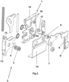
- zeigen das Blenden-Beschlagteil und -Montageteil, in Explosionsdarstellung in erster und zweiter perspektivischer Ansicht,
- Fig. 5
- zeigt ein Blenden-Beschlagteil und -Montageteil nach
Fig. 1 mit drei verschieden geneigten Stirnseiten in zusammengebautem Zustand und in Seitenansicht, - Fig. 6 + 7
- zeigen eine Seitenansicht eines Blenden-Beschlagteils und der -Montageteile für hohe Schubläden, in Explosionsdarstellung in erster und zweiter perspektivischer Ansicht,
- Fig. 8
- zeigt das Blenden-Beschlagteil und die -Montageteile nach
Fig. 6 in zusammengebautem Zustand und in Seitenansicht, - Fig. 9 + 10
- zeigen weitere Details des Feststell- und Auslösemechanismus.
- In
Fig. 1 ist ein Blenden-Beschlagteil 1 für eine nicht dargestellte Schublade dargestellt, wobei die Ansicht auf die der Seitenwand der Schublade zugekehrte Befestigungsseite gerichtet ist. Das Blenden-Beschlagteil 1 weist zur einfachen Verbindung mit dem Seitenteil der Schublade abgewinkelte Bereiche 14 auf, wobei die Verbindung mittels Schrauben, Nieten, rastbaren oder verpressbaren Bolzen etc. sicherbar ist. Ein mit dem Blenden-Beschlagteil 1 verbundenes Blenden-Montageteil 2 ist über Bohrungen 13 im Montageteil 2 und entsprechenden Schrauben 12 oder rastbaren Bolzenverbindungen mit der Rückseite der Blende verschraubt. Ein Feststellbolzen 3 des Blenden-Montageteils 2 verbindet dieses mit dem Feststellmittel 7 des Blenden-Beschlagteils 1 in einem vorgegebenen Abstand zur Rückseite der Blende. Die Blende der Schublade trägt zwei derartige Blenden-Montageteile 2, die mit entsprechenden Blenden-Beschlagteilen 1 verbunden sind, in einem Abstand, der auf die Abmessung der Außenseiten der beiden Seitenwände der offenen Stirnseite der Schublade angepasst ist. - Die
Fig. 1 zeigt auch zwei Schenkel einer zum Blenden-Beschlagteil 1 gerichteten Gabel 4 des Blenden-Montageteils 2, die einen als Exzenterbolzen ausgebildeten Einstellkörper 5 einfasst. Durch Drehen dieses Einstellkörpers 5 um seine Achse 5a kann die Lage der Gabel 4 um den Feststellbolzen 3 verschwenkt und damit die Neigung der Blende, beispielsweise mittels eines Kreuzschlitz-Schraubendrehers, verändert werden. Ferner ist ein Auslöseelement 6 dargestellt, das bei Betätigung in nicht dargestellter, aber in derDE 20 2014 002 229 U1 gezeigten Weise die beiden Teile 1, 2 voneinander trennt. Dieses Auslöseelement 6 kann mit einem ausklappbaren Betätigungsteil 6' ausgebildet sein. - Die
Fig. 2 zeigt den Feststellbolzen 3, welcher vorzugsweise drehbar und/oder horizontal verschiebbar ist, der in ein Feststellmittel 7 des Blenden-Beschlagteils 1 eingreift. Es können auch Mittel zur vertikalen und horizontalen Verstellung der Blende vorhanden sein. Mit Hilfe eines als Exzenterbolzen ausgebildeten Einstellkörpers 15, der in einer entsprechenden Durchbrechung des Blenden-Beschlagteils 1 gelagert und mit einem beweglichen Teil des Blenden-Beschlagteils verbunden ist, ist das Blenden-Montageteil 2 und damit die Blende relativ zum Blenden-Beschlagteil 1 vertikal verstellbar. Mit Hilfe einer Schraubverbindung des Feststellbolzens 3 mit dem Blenden-Montageteil 2 ist das Blenden-Montageteil 2 relativ zum Blenden-Beschlagteil 1 horizontal verstellbar, wobei der Feststellbolzen 3 in seinem inneren Bereich einen kleineren Durchmesser und an seinen beiden äußeren Bereichen einen größeren Durchmesser aufweist und die nach innen liegenden Anlageflächen der äußeren Bereiche in Wirkverbindung mit dem aufnehmenden Feststellmittel 7 des Blenden-Beschlagteils 1 bzw. mit dem Blenden-Beschlagteil 1 stehen und die horizontale Verstellung bewirken. - In den
Figuren 3 + 4 sind das Blenden-Beschlagteil und das Blenden-Montageteil, in Explosionsdarstellung in erster und zweiter perspektivischer Ansicht zu sehen. - Die
Fig. 5 zeigt ein Blenden-Beschlagteil nachFig. 1 mit drei verschieden geneigten Stirnseiten: - senkrecht
- geneigt nach oben
- geneigt nach unten
- Für hohe Schubläden ist die in den
Figuren 6 ,7 und8 gezeigte Ausführungsform vorteilhaft. - Die Blende gemäß den
Figuren 6 bis 8 trägt auf ihrer Rückseite ausgerichtete Blenden-Montageteile 2', 2" für jedes Seitenteil/Zarge und die Seitenwände der Schublade jeweils die Blenden-Montageteile 2`, 2" aufnehmende Blenden-Beschlagteile 1', die mittels Feststellmittel 7', 7" des Blenden-Beschlagteils 1' und Feststellbolzen 3', 3" der Blenden-Montageteile 2', 2" betrieblich verbindbar sind. Jedes Blenden-Beschlagteil ist also mit mindestens 2 Montageteilen 2', 2" verbunden. Die Blenden-Montageteile 2, 2' und die Blenden-Beschlagteile 1' weisen Mittel 4', 4", 8 zur Neigungseinstellung der Blende auf, die mit Einstellkörpern 5` der Blenden-Beschlagteile 1' in Wirkverbindung stehen. Zur Trennung der Teile 1' und 2', 2" kann das Betätigungsteil 6`, beziehungsweise das mit dem Betätigungsteil 6' wirkverbundene Auslöseelement 6 betätigt werden, wodurch die Feststellmittel 7', 7" von den Bolzen 3', 3" lösend getrennt werden. - Grundsätzlich kann es nach der vorliegenden Erfindung vorgesehen sein, dass mindestens zwei Auslöseelemente 6 vorgesehen sind, wobei jeweils ein Auslöseelement 6 jeweils eines der Feststellmittel 7', 7" von einem der Bolzen 3', 3" löst. Grundsätzlich können eine beliebige Anzahl von Feststellmitteln und entsprechenden Montageteilen 2, 2' an jedem der Blenden-Beschlagteile 1, 1' vorgesehen sein. Besonders bevorzugt können die einzelnen Feststellmittel bei jeder dieser Ausführungsformen unabhängig voneinander lösbar sein.
-
Figur 9 zeigt eine Ausführungsform des erfindungsgemäßen Beschlagteils 1,1', welches mit zwei Feststellmitteln 7', 7" ausgebildet ist, wobei die einzelnen Feststellmittel jeweils mit einem Auslöseelement 18, 19 wirkverbunden sind. Diese sind separat voneinander betätigbar, wobei jeweils ein Auslöseelement 18, 19 eines der Feststellmittel aus seiner Verbindung mit dem jeweiligen Bolzen löst. In den Beispielen II bis IV sind die beiden Auslöseelemente 18, 19 in verschiedenen Zuständen dargestellt.Figur 9 II zeigt die beiden Auslöseelemente 18, 19 in einer ersten Position, in welcher beide Feststellmittel 7`, 7" verschlossen sind.Figur 9 III zeigt das Auslöseelement 18 in einer gegenüber seiner ersten Position gemäßFigur 9 II nach unten ausgelenkten zweiten Position, wodurch das obere Feststellmittel 7" geöffnet wird. Die entsprechende Bewegung der Einzelteile wird durch die beiden Pfeile inFigur 9 III dargestellt. GemäßFigur 9 III bleibt bei der dort dargestellten Bewegung des Ausleselöseelements 18 das Auslöseelement 19 in seiner ersten Position gemäßFigur 9 II, wobei das untere Feststellmittel 7' in seinem verschlossenen Zustand gemäßFigur 9 II verbleibt. - Gemäß
Figur 9 IV verbleibt das Auslöseelement 18 in einer seiner ersten Position gemäßFigur 9 II, wobei das Auslöseelement 19 in eine zweite Position nach unten verlagert wird. Durch diese Verlagerung wird das untere Feststellmittel 7' geöffnet. Die beiden miteinander in Zusammenhang stehenden Bewegungen von Auslöseelement 19 und Feststellmittel 7' sind durch die inFigur 9 IV dargestellten Pfeile verdeutlicht. Grundsätzlich können die beiden Auslöseelemente 18, 19 gleichzeitig jedoch unabhängig voneinander betätigt werden. - Wie besonders durch einen Vergleich der
Figuren 9 II und 9 III verdeutlicht wird, kann für eine ordnungsgemäße Bewegung der einzelnen Feststellmittel 7', 7" eine Verschiebung des Verbindungselements 17 entlang einer Führungspartie, welche als Langnut 16 ausgebildet sein kann, erforderlich. In einem geschlossenen Zustand, wie er beispielsweise inFigur 9 II dargestellt ist, befindet sich das Verbindungselement 17 in einem rechten beziehungsweise hinteren Bereich der Führungspartie/Langnut 16. Beim Öffnen des Feststellmittels, wie es beispielsweise inFigur 9 III für das Feststellmittel 7" dargestellt ist, wird das Verbindungselement 17 zusammen mit dem Feststellmittel 7" nach links beziehungsweise in einen vorderen Bereich der Langnut 16 verschoben. - Nach dieser Ausführungsvariante kann demnach davon gesprochen werden, dass das Feststellmittel 7', 7" für seine Bewegung zwischen einer geöffneten und einer geschlossenen Position keine Rotationsachse mit festem Bezugssystem aufweist sondern vielmehr mit einer Führungspartie verwirklicht ist, innerhalb welcher eine Verlagerung des Feststellmittels 7', 7" durch Translation bewirkt wird.
- Oberhalb jedes Feststellmittels 7', 7" kann ein Vorsprung 20 vorgesehen sein, welcher verhindert, dass das Feststellmittel 7', 7" durch bloße Rotation des Feststellmittels 7', 7" um das Verbindungselement 17 aus einer geschlossenen in eine geöffnete Position verlagerbar ist. Erfindungsgemäß kann daher eine Sicherung, vorzugsweise in Form des Vorsprungs 20 bestehen, die die Bewegung des Feststellmittels 7', 7" von einer geschlossenen in eine geöffnete Position nur dann ermöglicht, wenn eine Translation des Verbindungselements 17 an dem Feststellmittel 7', 7" aus einer hinteren beziehungsweise zurückgezogenen Position entlang der Führungspartie/Langnut 16 in eine vordere Position der Führungspartie/Langnut 16 erfolgt. Die vordere Position kann hierbei der Blende der Schublade zugewandt sein.
- Eine geöffnete Position eines Feststellmittels 7', 7" kann insbesondere dann vorliegen, wenn ein Bolzen 3', 3" aus einem Aufnahmebereich des Feststellmittels 7', 7" entfernbar und somit eine Verbindung zwischen dem Blenden-Beschlagteil 1' und dem Blenden-Montageteil 2', 2" lösbar ist.
-
Figur 9 I zeigt die Auslöseelemente 18 und 19 gegenüber dem Blenden-Beschlagteil 1' in einer Explosionsdarstellung. Die Auslöseelemente 18 und 19 können gegenseitig jeweils als schienenartige Führung für das andere Auslöseelement dienen, wobei eine Betätigung der beiden Auslöseelemente 18, 19 jeweils in einem unteren Bereich des Blenden-Beschlagteils 1' ermöglicht ist. Hierfür kann wiederum jeweils ein Betätigungsteil 6' an dem jeweiligen Auslöseelement 18, 19 vorgesehen sein, welches vorzugsweise ausklappbar ist. -
Figur 10 zeigt eine Ausführungsform des erfindungsgemäßen Blenden-Beschlagteils 1', bei welchem mittels eines einheitlichen Auslöseelements 6 eine entkoppelte Öffnungsbewegung zwischen den beiden Feststellmitteln 7', 7" bewirkbar ist.Figur 10 I zeigt die Ausführungsform in einer Explosionsdarstellung mit einem Auslöseelemente 6, an welchem ein Eingriff 21 in eine Feder 22 vorgesehen ist, wobei die Feder 22 auf das untere Feststellmittel 7' direkt oder indirekt zum Öffnen des Feststellmittels einwirken kann. In einem oberen Bereich des Auslöseelements 6 ist eine Öffnung 23 angeordnet, welche mit einem Betätigungselement zum Öffnen des oberen Feststellmittels 7" in Verbindung steht. - Durch eine schrittweise Betätigung des Auslöseelements 6 können nacheinander zuerst das untere Feststellmittel 7' durch eine Bewegung des Auslöseelements 6 in eine erste Position nach unten geöffnet werden und anschließend das obere Feststellmittel 7" durch eine weitere Bewegung des Auslöseelements 6 in eine zweite Position, welche vorzugsweise noch weiter unten als die erste Position gegenüber einer Ausgangsposition, wie sie in
Figur 10 II dargestellt ist, geöffnet werden. Die jeweilige Bewegung des Auslöseelements 6 und die daraus resultierende Öffnung der einzelnen Feststellmittel 7', 7" nacheinander ist in denFiguren 10 III bis V durch die Pfeile am Auslöseelemente 6 und den Feststellmitteln 7', 7" dargestellt. - Ein gemeinsames Lösen der beiden Feststellmittel 7', 7" durch Betätigen des gemeinsamen Auslöseelements 6 von ihren jeweiligen Bolzen, beziehungsweise aus ihrer geschlossenen Position in eine geöffnete Position, ist somit durch die Ausführungsform gemäß
Figur 10 I bis V vermieden. - Die Mittel zur Neigungsverstellung umfassen ein längliches, auf dem Blenden-Beschlagteil 1' vertikal angeordnetes Leitblech 8, wobei das Ende 9' des Leitblechs 8 bzw. der Einstellkörper 5' abwechselnd an Endanlageflächen 4`, 4" des Blenden-Montageteils 2' und einem über diesem angeordneten, zusätzlichen Blenden-Montageteil 2" anlegbar sind und ein Ende des Leitblechs 8 mit einem Einstellkörper 5' in Verbindung steht. Das Leitblech 8 ist in der Mitte mit einem Langloch 10 versehen, in dem ein Gleitbolzen 11 gleitet. Durch Drehen des als Exzenterbolzen ausgebildeten Einstellkörpers 5` um seine Achse 5a`, wird nach
Fig. 8 entweder das untere Blenden-Montageteil 2' oder das obere Blenden-Montageteil 2" verstellt und so ein Verschwenken der Blende um den als Achse wirkenden Gleitbolzen 11 entweder nach oben oder unten bewirkt. Der Einstellkörper 5' ist dazu durch eine Ausnehmung des Leitblechs 8 an seinem einen Ende 9 geführt und im Blenden-Beschlagteil 1' gelagert, wobei der Einstellkörper 5` auch als Wirkfläche zur Erzeugung der Verschiebekraft an der Endanlagefläche 4' des Blenden-Montageteils 2' dient. Das Leitblech 8 weist außerdem an seinem anderen Ende 9' ein um 90° abgewinkeltes Teil auf, welches ebenfalls als Wirkfläche zur Erzeugung der Verschiebekraft an der Endanlagefläche 4" des Blenden-Montageteils 2" dient. - Die Achse 5a, 5a' des Einstellkörpers und die Verschwenkachse der Blende verlaufen parallel zur Boden- oder Deckseite der Schublade und die Blende ist zu ihrer optimalen Einstellung und Ausrichtung zum Schrankkorpus um einen Winkel von bis zu +/- 5 Grad verschwenkbar.
Claims (9)
- Befestigungsbeschlag zur Befestigung einer Blende an einer Schublade, wobei der Befestigungsbeschlag Blenden-Beschlagteile (1, 1') zur Montage an Seitenwänden der Schublade und Blenden-Montageteile (2, 2', 2") zur Montage an einer Rückseite der Blende umfasst, wobei die Blenden-Beschlagteile (1, 1') die Blenden-Montageteile (2, 2', 2") aufnehmen, wobei diese mittels Feststellmitteln (7, 7', 7") der Blenden-Beschlagteile (1, 1') und Feststellbolzen (3, 3', 3") der Blenden-Montageteile (2, 2', 2") verbindbar sind, wobei jedes der Blenden-Montageteile (2, 2`, 2") Mittel (4, 4', 4") zur Neigungseinstellung der Blende aufweist, die mit jeweils einem als Exzenterbolzen ausgebildeten Einstellkörper (5, 5') der Blenden-Beschlagteile (1, 1') in Wirkverbindung stehen und die Blende um eine parallel zur Boden- oder Deckseite der Schublade verlaufende Achse verschwenken, und wobei die Feststellmittel (7`, 7") jeweils in einer Führungspartie verschiebbar angeordnet und entlang der Führungspartie zwischen einer geöffneten Position der Feststellmittel (7`, 7") und einer geschlossenen Position der Feststellmittel (7`, 7") verfahrbar sind,
dadurch gekennzeichnet,dass entweder die Mittel zur Neigungsverstellung eine zum Blenden-Beschlagteil (1) gerichtete Gabel (4) des Blenden-Montageteils (2) umfassen, die den Exzenterbolzen (5) aufnimmt oderdass die Mittel zur Neigungsverstellung ein längliches, auf dem Blenden-Beschlagteil (1') vertikal angeordnetes Leitblech (8) umfassen, wobei der Exzenterbolzen (5`) bzw. ein Ende (9') des Leitblechs (8) abwechselnd an Endanlageflächen (4', 4") des Blenden-Montageteils (2') und einem über diesem angeordneten, zusätzlichen Blenden-Montageteil (2") anlegbar sind und wobei ein zweites Ende (9) des Leitblechs (8) mit dem Exzenterbolzen (5`) in Verbindung steht. - Befestigungsbeschlag nach einem der vorhergehenden Ansprüche,
dadurch gekennzeichnet,
dass die Achse (5a, 5a`) des Exzenterbolzen (5, 5') und die Verschwenkachse der Blende parallel verlaufen. - Befestigungsbeschlag nach einem der vorhergehenden Ansprüche,
dadurch gekennzeichnet,
dass die Blende um einen Winkel von bis zu +/- 5 Grad verschwenkbar ist. - Befestigungsbeschlag nach einem der vorhergehenden Ansprüche,
dadurch gekennzeichnet,
dass der Exzenterbolzen (5`) durch eine Ausnehmung des Leitblechs (8) an seinem einen Ende (9) geführt und im Blenden-Beschlagteil (1') gelagert ist und dass das Leitblech (8) an seinem anderen Ende (9') ein um 90° abgewinkeltes Teil aufweist. - Befestigungsbeschlag nach einem der vorhergehenden Ansprüche,
dadurch gekennzeichnet,
dass das Blenden-Montageteil (2, 2', 2") relativ zum Blenden-Beschlagteil (1, 1') vertikal verstellbar ist. - Befestigungsbeschlag nach einem der vorhergehenden Ansprüche,
dadurch gekennzeichnet,
dass das Blenden-Montageteil (2, 2', 2") relativ zum Blenden-Beschlagteil (1, 1') horizontal verstellbar ist. - Befestigungsbeschlag nach einem der vorhergehenden Ansprüche,
dadurch gekennzeichnet,
dass mindestens ein Auslöseelement (6) zum Lösen der Verbindung zwischen Feststellmittel (7, 7', 7") und dem Blenden-Montageteil (2, 2', 2") an dem Blendenbeschlagteil (1, 1') vorgesehen ist. - Befestigungsbeschlag nach einem der vorhergehenden Ansprüche,
dadurch gekennzeichnet,
dass das Blenden-Beschlagteil (1') mindestens zwei Feststellmittel (7`, 7") aufweist, wobei die einzelnen Feststellmittel mittels separater Auslöseelemente (6) lösbar sind. - Befestigungsbeschlag nach einem der vorhergehenden Ansprüche,
dadurch gekennzeichnet,
dass durch Betätigen eines einzelnen Auslöseelements (6) an einem Blenden-Beschlagteil (1 `) die Verbindungen zwischen mindestens zwei Blenden-Montageteilen (2', 2") und den jeweiligen Feststellmitteln (7`, 7") des Blenden-Beschlagteils (1') lösbar sind, wobei eine Entkoppelungseinrichtung mit dem Auslöseelement (6) in Wirkverbindung steht, und ausgebildet ist, die einzelnen Verbindungen zwischen Feststellmitteln (7`, 7") und Blenden-Montageteilen (2', 2") verzögert beziehungsweise zeitlich versetzt zu einander zu lösen.
Applications Claiming Priority (2)
| Application Number | Priority Date | Filing Date | Title |
|---|---|---|---|
| EP17170432 | 2017-05-10 | ||
| PCT/EP2018/062145 WO2018206727A1 (de) | 2017-05-10 | 2018-05-09 | Befestigungsbeschlag für eine blende |
Publications (2)
| Publication Number | Publication Date |
|---|---|
| EP3621485A1 EP3621485A1 (de) | 2020-03-18 |
| EP3621485B1 true EP3621485B1 (de) | 2023-02-08 |
Family
ID=58707314
Family Applications (1)
| Application Number | Title | Priority Date | Filing Date |
|---|---|---|---|
| EP18724522.0A Active EP3621485B1 (de) | 2017-05-10 | 2018-05-09 | Befestigungsbeschlag für eine blende |
Country Status (4)
| Country | Link |
|---|---|
| US (1) | US11071381B2 (de) |
| EP (1) | EP3621485B1 (de) |
| CN (1) | CN110730621B (de) |
| WO (1) | WO2018206727A1 (de) |
Families Citing this family (3)
| Publication number | Priority date | Publication date | Assignee | Title |
|---|---|---|---|---|
| AT521512B1 (de) * | 2018-10-05 | 2020-02-15 | Blum Gmbh Julius | Befestigungsvorrichtung zum lösbaren Befestigen einer Frontblende an einer Schublade |
| AT17224U1 (de) * | 2020-05-15 | 2021-09-15 | Van Hoecke Nv | Anordnung aus einer Schubladenseitenwand und einer Verbindungsvorrichtung |
| CN116268827B (zh) * | 2023-04-15 | 2026-02-27 | 广东东泰五金精密制造有限公司 | 一种具有调节机构的抽屉组件 |
Family Cites Families (26)
| Publication number | Priority date | Publication date | Assignee | Title |
|---|---|---|---|---|
| AT393203B (de) | 1987-12-07 | 1991-09-10 | Alfit Gmbh | Schublade mit auszugsgarnitur |
| AT398514B (de) * | 1990-07-12 | 1994-12-27 | Alfit Ag | Schublade mit metallischen zargen |
| DE19944642A1 (de) * | 1999-09-17 | 2001-03-22 | Hettich Paul Gmbh & Co | Befestigungsvorrichtung |
| DE19944639A1 (de) * | 1999-09-17 | 2001-03-22 | Hettich Paul Gmbh & Co | Befestigungsanordnung |
| DE102009025890A1 (de) | 2009-05-29 | 2011-06-22 | Paul Hettich GmbH & Co. KG, 32278 | Vorrichtung zur Befestigung einer Frontblende an einer Seitenzarge eines beweglichen Möbelteils eines Möbels, Schubkasten und Möbel |
| AT509411B1 (de) * | 2010-02-03 | 2012-05-15 | Blum Gmbh Julius | Schubladenzarge |
| CN102058253B (zh) * | 2010-10-27 | 2012-12-26 | 东莞世巨五金塑胶制品有限公司 | 抽屉面板角度调整结构 |
| AT510779B1 (de) * | 2010-11-23 | 2014-09-15 | Blum Gmbh Julius | Möbelbeschlag zur frontblendenbefestigung |
| AT511294B1 (de) * | 2011-04-11 | 2013-06-15 | Blum Gmbh Julius | Schubladenausziehführung |
| AT511538B1 (de) * | 2011-05-24 | 2013-06-15 | Blum Gmbh Julius | Befestigungsvorrichtung zum befestigen einer frontblende an einer schublade |
| AT510954B1 (de) * | 2011-05-24 | 2012-08-15 | Blum Gmbh Julius | Rastgesperre für möbelstücke |
| AT511066B1 (de) * | 2011-05-24 | 2012-09-15 | Blum Gmbh Julius | Befestigungsvorrichtung zum befestigen einer frontblende an einer schublade |
| US8585166B2 (en) * | 2011-07-14 | 2013-11-19 | King Slide Works Co., Ltd. | Slide assembly and connection device |
| AT512236B1 (de) * | 2011-11-22 | 2015-10-15 | Blum Gmbh Julius | Befestigungsvorrichtung zum befestigen einer frontblende an einer schublade |
| CN203302661U (zh) * | 2013-04-23 | 2013-11-27 | 广东泰明金属制品有限公司 | 抽屉面板调节装置 |
| DE202014002229U1 (de) | 2014-03-14 | 2014-04-29 | Erwin Krüger | Befestigungsbeschlag für eine Blende an einer offenen Stirnseite einer Schublade |
| US9185976B2 (en) * | 2014-04-08 | 2015-11-17 | King Slide Works Co., Ltd. | Adjusting device |
| DE102014011090A1 (de) * | 2014-07-30 | 2016-02-04 | Erwin Krüger | Befestigungsbeschlag für eine Blende an einer offenen Stirnseite einer Schublade |
| DE102014113954B4 (de) * | 2014-09-26 | 2022-07-14 | Samet Kalip Ve Maden Esya San. Ve Tic. A.S. | Verstelleinrichtung |
| CN204232569U (zh) * | 2014-10-07 | 2015-04-01 | 宿州学院 | 一种多功能学生课桌 |
| AT516838B1 (de) * | 2015-03-13 | 2016-09-15 | Blum Gmbh Julius | Befestigungsvorrichtung zum lösbaren Befestigen einer Frontblende an einer Schublade |
| CN107809927A (zh) * | 2015-06-15 | 2018-03-16 | 形橙产品开发公司 | 具有底板、两个侧壁、后壁以及挡板的抽屉 |
| TWI548371B (zh) * | 2015-11-12 | 2016-09-11 | 川湖科技股份有限公司 | 抽屜滑軌組件及其安裝裝置 |
| US10010174B2 (en) * | 2015-11-12 | 2018-07-03 | King Slide Works Co., Ltd. | Mounting mechanism |
| US9752817B2 (en) * | 2015-12-18 | 2017-09-05 | Whirlpool Corporation | Door/drawer panel adjustment mechanism for an appliance |
| CN108433407A (zh) * | 2017-02-16 | 2018-08-24 | 苏树鹏 | 抽屉面板调整装置 |
-
2018
- 2018-05-09 EP EP18724522.0A patent/EP3621485B1/de active Active
- 2018-05-09 US US16/611,108 patent/US11071381B2/en active Active
- 2018-05-09 WO PCT/EP2018/062145 patent/WO2018206727A1/de not_active Ceased
- 2018-05-09 CN CN201880038433.2A patent/CN110730621B/zh active Active
Also Published As
| Publication number | Publication date |
|---|---|
| US11071381B2 (en) | 2021-07-27 |
| EP3621485A1 (de) | 2020-03-18 |
| US20200054132A1 (en) | 2020-02-20 |
| WO2018206727A1 (de) | 2018-11-15 |
| CN110730621A (zh) | 2020-01-24 |
| CN110730621B (zh) | 2021-11-02 |
Similar Documents
| Publication | Publication Date | Title |
|---|---|---|
| AT515425B1 (de) | Vorrichtung zur befestigung einer frontblende an einer seitenzarge eines beweglichen möbelteils eines möbels, schubkasten und möbel | |
| EP3542672B1 (de) | Möbelbeschlag zur frontblendenbefestigung | |
| EP2531065B1 (de) | Schubladenzarge | |
| EP2294957B1 (de) | Vorrichtung zur Halterung von flächenförmigen Elementen | |
| EP3625417B1 (de) | In seiner länge einstellbarer steuerarm | |
| EP3088645B1 (de) | Verbindungsvorrichtung für eine schiebetür | |
| EP3621483B1 (de) | Haltevorrichtung für eine frontblende einer schublade | |
| EP1605796B1 (de) | Schublade | |
| DE202004012298U1 (de) | Haushaltsgerät mit verschwenkbarem Anzeigeschirm | |
| WO2018206727A1 (de) | Befestigungsbeschlag für eine blende | |
| DE102012100974B4 (de) | Lüfter und Anordnung aufweisend einen derartigen Lüfter | |
| EP3621484A2 (de) | Haltevorrichtung für eine frontblende einer schublade | |
| EP3704337B1 (de) | Bandteil | |
| EP3009043B1 (de) | Schubkasten mit einer verstellvorrichtung für die ausrichtung der frontblende | |
| EP3666120B1 (de) | Schubladenfront-verbindungsvorrichtung und schublade | |
| EP3737262B1 (de) | Anordnung aus ausziehführung und mitnehmer | |
| EP2038498A1 (de) | Band für türen, fenster oder dergleichen | |
| WO2025255591A1 (de) | Befestigungsvorrichtung zur lösbaren befestigung einer frontblende an einer schublade | |
| EP3689184B1 (de) | Vorrichtung zur einstellung einer schliessposition einer schublade, korpusschiene, schubladenführung und schublade | |
| DE102024207145A1 (de) | Frontblendenbeschlag | |
| WO2020070121A1 (de) | Befestigungsvorrichtung zum befestigen einer blende eines schubkastens an einer zarge | |
| EP4153017A1 (de) | Behälteraufnahmevorrichtung und halterung hierzu | |
| EP1936063A2 (de) | Stellmechanismus für einen Sonnenschirm | |
| DE202005013245U1 (de) | Scheinwerfer |
Legal Events
| Date | Code | Title | Description |
|---|---|---|---|
| STAA | Information on the status of an ep patent application or granted ep patent |
Free format text: STATUS: UNKNOWN |
|
| STAA | Information on the status of an ep patent application or granted ep patent |
Free format text: STATUS: THE INTERNATIONAL PUBLICATION HAS BEEN MADE |
|
| PUAI | Public reference made under article 153(3) epc to a published international application that has entered the european phase |
Free format text: ORIGINAL CODE: 0009012 |
|
| STAA | Information on the status of an ep patent application or granted ep patent |
Free format text: STATUS: REQUEST FOR EXAMINATION WAS MADE |
|
| 17P | Request for examination filed |
Effective date: 20191210 |
|
| AK | Designated contracting states |
Kind code of ref document: A1 Designated state(s): AL AT BE BG CH CY CZ DE DK EE ES FI FR GB GR HR HU IE IS IT LI LT LU LV MC MK MT NL NO PL PT RO RS SE SI SK SM TR |
|
| AX | Request for extension of the european patent |
Extension state: BA ME |
|
| DAV | Request for validation of the european patent (deleted) | ||
| DAX | Request for extension of the european patent (deleted) | ||
| STAA | Information on the status of an ep patent application or granted ep patent |
Free format text: STATUS: EXAMINATION IS IN PROGRESS |
|
| 17Q | First examination report despatched |
Effective date: 20210203 |
|
| GRAP | Despatch of communication of intention to grant a patent |
Free format text: ORIGINAL CODE: EPIDOSNIGR1 |
|
| STAA | Information on the status of an ep patent application or granted ep patent |
Free format text: STATUS: GRANT OF PATENT IS INTENDED |
|
| INTG | Intention to grant announced |
Effective date: 20220826 |
|
| GRAS | Grant fee paid |
Free format text: ORIGINAL CODE: EPIDOSNIGR3 |
|
| GRAA | (expected) grant |
Free format text: ORIGINAL CODE: 0009210 |
|
| STAA | Information on the status of an ep patent application or granted ep patent |
Free format text: STATUS: THE PATENT HAS BEEN GRANTED |
|
| AK | Designated contracting states |
Kind code of ref document: B1 Designated state(s): AL AT BE BG CH CY CZ DE DK EE ES FI FR GB GR HR HU IE IS IT LI LT LU LV MC MK MT NL NO PL PT RO RS SE SI SK SM TR |
|
| REG | Reference to a national code |
Ref country code: GB Ref legal event code: FG4D Free format text: NOT ENGLISH |
|
| REG | Reference to a national code |
Ref country code: CH Ref legal event code: EP Ref country code: AT Ref legal event code: REF Ref document number: 1547279 Country of ref document: AT Kind code of ref document: T Effective date: 20230215 |
|
| REG | Reference to a national code |
Ref country code: IE Ref legal event code: FG4D Free format text: LANGUAGE OF EP DOCUMENT: GERMAN |
|
| REG | Reference to a national code |
Ref country code: DE Ref legal event code: R096 Ref document number: 502018011561 Country of ref document: DE |
|
| REG | Reference to a national code |
Ref country code: LT Ref legal event code: MG9D |
|
| REG | Reference to a national code |
Ref country code: NL Ref legal event code: MP Effective date: 20230208 |
|
| PG25 | Lapsed in a contracting state [announced via postgrant information from national office to epo] |
Ref country code: RS Free format text: LAPSE BECAUSE OF FAILURE TO SUBMIT A TRANSLATION OF THE DESCRIPTION OR TO PAY THE FEE WITHIN THE PRESCRIBED TIME-LIMIT Effective date: 20230208 Ref country code: PT Free format text: LAPSE BECAUSE OF FAILURE TO SUBMIT A TRANSLATION OF THE DESCRIPTION OR TO PAY THE FEE WITHIN THE PRESCRIBED TIME-LIMIT Effective date: 20230609 Ref country code: NO Free format text: LAPSE BECAUSE OF FAILURE TO SUBMIT A TRANSLATION OF THE DESCRIPTION OR TO PAY THE FEE WITHIN THE PRESCRIBED TIME-LIMIT Effective date: 20230508 Ref country code: NL Free format text: LAPSE BECAUSE OF FAILURE TO SUBMIT A TRANSLATION OF THE DESCRIPTION OR TO PAY THE FEE WITHIN THE PRESCRIBED TIME-LIMIT Effective date: 20230208 Ref country code: LV Free format text: LAPSE BECAUSE OF FAILURE TO SUBMIT A TRANSLATION OF THE DESCRIPTION OR TO PAY THE FEE WITHIN THE PRESCRIBED TIME-LIMIT Effective date: 20230208 Ref country code: LT Free format text: LAPSE BECAUSE OF FAILURE TO SUBMIT A TRANSLATION OF THE DESCRIPTION OR TO PAY THE FEE WITHIN THE PRESCRIBED TIME-LIMIT Effective date: 20230208 Ref country code: HR Free format text: LAPSE BECAUSE OF FAILURE TO SUBMIT A TRANSLATION OF THE DESCRIPTION OR TO PAY THE FEE WITHIN THE PRESCRIBED TIME-LIMIT Effective date: 20230208 Ref country code: ES Free format text: LAPSE BECAUSE OF FAILURE TO SUBMIT A TRANSLATION OF THE DESCRIPTION OR TO PAY THE FEE WITHIN THE PRESCRIBED TIME-LIMIT Effective date: 20230208 |
|
| PG25 | Lapsed in a contracting state [announced via postgrant information from national office to epo] |
Ref country code: SE Free format text: LAPSE BECAUSE OF FAILURE TO SUBMIT A TRANSLATION OF THE DESCRIPTION OR TO PAY THE FEE WITHIN THE PRESCRIBED TIME-LIMIT Effective date: 20230208 Ref country code: PL Free format text: LAPSE BECAUSE OF FAILURE TO SUBMIT A TRANSLATION OF THE DESCRIPTION OR TO PAY THE FEE WITHIN THE PRESCRIBED TIME-LIMIT Effective date: 20230208 Ref country code: IS Free format text: LAPSE BECAUSE OF FAILURE TO SUBMIT A TRANSLATION OF THE DESCRIPTION OR TO PAY THE FEE WITHIN THE PRESCRIBED TIME-LIMIT Effective date: 20230608 Ref country code: GR Free format text: LAPSE BECAUSE OF FAILURE TO SUBMIT A TRANSLATION OF THE DESCRIPTION OR TO PAY THE FEE WITHIN THE PRESCRIBED TIME-LIMIT Effective date: 20230509 Ref country code: FI Free format text: LAPSE BECAUSE OF FAILURE TO SUBMIT A TRANSLATION OF THE DESCRIPTION OR TO PAY THE FEE WITHIN THE PRESCRIBED TIME-LIMIT Effective date: 20230208 |
|
| PG25 | Lapsed in a contracting state [announced via postgrant information from national office to epo] |
Ref country code: SM Free format text: LAPSE BECAUSE OF FAILURE TO SUBMIT A TRANSLATION OF THE DESCRIPTION OR TO PAY THE FEE WITHIN THE PRESCRIBED TIME-LIMIT Effective date: 20230208 Ref country code: RO Free format text: LAPSE BECAUSE OF FAILURE TO SUBMIT A TRANSLATION OF THE DESCRIPTION OR TO PAY THE FEE WITHIN THE PRESCRIBED TIME-LIMIT Effective date: 20230208 Ref country code: EE Free format text: LAPSE BECAUSE OF FAILURE TO SUBMIT A TRANSLATION OF THE DESCRIPTION OR TO PAY THE FEE WITHIN THE PRESCRIBED TIME-LIMIT Effective date: 20230208 Ref country code: DK Free format text: LAPSE BECAUSE OF FAILURE TO SUBMIT A TRANSLATION OF THE DESCRIPTION OR TO PAY THE FEE WITHIN THE PRESCRIBED TIME-LIMIT Effective date: 20230208 Ref country code: CZ Free format text: LAPSE BECAUSE OF FAILURE TO SUBMIT A TRANSLATION OF THE DESCRIPTION OR TO PAY THE FEE WITHIN THE PRESCRIBED TIME-LIMIT Effective date: 20230208 |
|
| REG | Reference to a national code |
Ref country code: DE Ref legal event code: R097 Ref document number: 502018011561 Country of ref document: DE |
|
| PG25 | Lapsed in a contracting state [announced via postgrant information from national office to epo] |
Ref country code: SK Free format text: LAPSE BECAUSE OF FAILURE TO SUBMIT A TRANSLATION OF THE DESCRIPTION OR TO PAY THE FEE WITHIN THE PRESCRIBED TIME-LIMIT Effective date: 20230208 |
|
| PLBE | No opposition filed within time limit |
Free format text: ORIGINAL CODE: 0009261 |
|
| STAA | Information on the status of an ep patent application or granted ep patent |
Free format text: STATUS: NO OPPOSITION FILED WITHIN TIME LIMIT |
|
| REG | Reference to a national code |
Ref country code: CH Ref legal event code: PL |
|
| 26N | No opposition filed |
Effective date: 20231109 |
|
| PG25 | Lapsed in a contracting state [announced via postgrant information from national office to epo] |
Ref country code: MC Free format text: LAPSE BECAUSE OF FAILURE TO SUBMIT A TRANSLATION OF THE DESCRIPTION OR TO PAY THE FEE WITHIN THE PRESCRIBED TIME-LIMIT Effective date: 20230208 |
|
| GBPC | Gb: european patent ceased through non-payment of renewal fee |
Effective date: 20230509 |
|
| REG | Reference to a national code |
Ref country code: BE Ref legal event code: MM Effective date: 20230531 |
|
| PG25 | Lapsed in a contracting state [announced via postgrant information from national office to epo] |
Ref country code: SI Free format text: LAPSE BECAUSE OF FAILURE TO SUBMIT A TRANSLATION OF THE DESCRIPTION OR TO PAY THE FEE WITHIN THE PRESCRIBED TIME-LIMIT Effective date: 20230208 Ref country code: MC Free format text: LAPSE BECAUSE OF FAILURE TO SUBMIT A TRANSLATION OF THE DESCRIPTION OR TO PAY THE FEE WITHIN THE PRESCRIBED TIME-LIMIT Effective date: 20230208 Ref country code: LU Free format text: LAPSE BECAUSE OF NON-PAYMENT OF DUE FEES Effective date: 20230509 Ref country code: LI Free format text: LAPSE BECAUSE OF NON-PAYMENT OF DUE FEES Effective date: 20230531 Ref country code: CH Free format text: LAPSE BECAUSE OF NON-PAYMENT OF DUE FEES Effective date: 20230531 |
|
| REG | Reference to a national code |
Ref country code: IE Ref legal event code: MM4A |
|
| PG25 | Lapsed in a contracting state [announced via postgrant information from national office to epo] |
Ref country code: IE Free format text: LAPSE BECAUSE OF NON-PAYMENT OF DUE FEES Effective date: 20230509 |
|
| PG25 | Lapsed in a contracting state [announced via postgrant information from national office to epo] |
Ref country code: IE Free format text: LAPSE BECAUSE OF NON-PAYMENT OF DUE FEES Effective date: 20230509 Ref country code: GB Free format text: LAPSE BECAUSE OF NON-PAYMENT OF DUE FEES Effective date: 20230509 |
|
| PG25 | Lapsed in a contracting state [announced via postgrant information from national office to epo] |
Ref country code: FR Free format text: LAPSE BECAUSE OF NON-PAYMENT OF DUE FEES Effective date: 20230531 Ref country code: BE Free format text: LAPSE BECAUSE OF NON-PAYMENT OF DUE FEES Effective date: 20230531 |
|
| PG25 | Lapsed in a contracting state [announced via postgrant information from national office to epo] |
Ref country code: BG Free format text: LAPSE BECAUSE OF FAILURE TO SUBMIT A TRANSLATION OF THE DESCRIPTION OR TO PAY THE FEE WITHIN THE PRESCRIBED TIME-LIMIT Effective date: 20230208 |
|
| PG25 | Lapsed in a contracting state [announced via postgrant information from national office to epo] |
Ref country code: BG Free format text: LAPSE BECAUSE OF FAILURE TO SUBMIT A TRANSLATION OF THE DESCRIPTION OR TO PAY THE FEE WITHIN THE PRESCRIBED TIME-LIMIT Effective date: 20230208 |
|
| PGFP | Annual fee paid to national office [announced via postgrant information from national office to epo] |
Ref country code: DE Payment date: 20250530 Year of fee payment: 8 |
|
| PGFP | Annual fee paid to national office [announced via postgrant information from national office to epo] |
Ref country code: IT Payment date: 20250530 Year of fee payment: 8 |
|
| PGFP | Annual fee paid to national office [announced via postgrant information from national office to epo] |
Ref country code: AT Payment date: 20250602 Year of fee payment: 8 |
|
| PG25 | Lapsed in a contracting state [announced via postgrant information from national office to epo] |
Ref country code: CY Free format text: LAPSE BECAUSE OF FAILURE TO SUBMIT A TRANSLATION OF THE DESCRIPTION OR TO PAY THE FEE WITHIN THE PRESCRIBED TIME-LIMIT; INVALID AB INITIO Effective date: 20180509 |
|
| PG25 | Lapsed in a contracting state [announced via postgrant information from national office to epo] |
Ref country code: HU Free format text: LAPSE BECAUSE OF FAILURE TO SUBMIT A TRANSLATION OF THE DESCRIPTION OR TO PAY THE FEE WITHIN THE PRESCRIBED TIME-LIMIT; INVALID AB INITIO Effective date: 20180509 |
|
| PG25 | Lapsed in a contracting state [announced via postgrant information from national office to epo] |
Ref country code: TR Free format text: LAPSE BECAUSE OF FAILURE TO SUBMIT A TRANSLATION OF THE DESCRIPTION OR TO PAY THE FEE WITHIN THE PRESCRIBED TIME-LIMIT Effective date: 20230208 |