EP3621485B1 - Ferrure de fixation pour une façade de tiroir - Google Patents
Ferrure de fixation pour une façade de tiroir Download PDFInfo
- Publication number
- EP3621485B1 EP3621485B1 EP18724522.0A EP18724522A EP3621485B1 EP 3621485 B1 EP3621485 B1 EP 3621485B1 EP 18724522 A EP18724522 A EP 18724522A EP 3621485 B1 EP3621485 B1 EP 3621485B1
- Authority
- EP
- European Patent Office
- Prior art keywords
- panel
- fitting
- locking means
- parts
- fastening
- Prior art date
- Legal status (The legal status is an assumption and is not a legal conclusion. Google has not performed a legal analysis and makes no representation as to the accuracy of the status listed.)
- Active
Links
Images


Classifications
-
- A—HUMAN NECESSITIES
- A47—FURNITURE; DOMESTIC ARTICLES OR APPLIANCES; COFFEE MILLS; SPICE MILLS; SUCTION CLEANERS IN GENERAL
- A47B—TABLES; DESKS; OFFICE FURNITURE; CABINETS; DRAWERS; GENERAL DETAILS OF FURNITURE
- A47B88/00—Drawers for tables, cabinets or like furniture; Guides for drawers
- A47B88/90—Constructional details of drawers
- A47B88/944—Drawers characterised by the front panel
- A47B88/95—Drawers characterised by the front panel characterised by connection means for the front panel
- A47B88/956—Drawers characterised by the front panel characterised by connection means for the front panel for enabling adjustment of the front panel
-
- A—HUMAN NECESSITIES
- A47—FURNITURE; DOMESTIC ARTICLES OR APPLIANCES; COFFEE MILLS; SPICE MILLS; SUCTION CLEANERS IN GENERAL
- A47B—TABLES; DESKS; OFFICE FURNITURE; CABINETS; DRAWERS; GENERAL DETAILS OF FURNITURE
- A47B88/00—Drawers for tables, cabinets or like furniture; Guides for drawers
- A47B88/90—Constructional details of drawers
- A47B88/941—Drawers being constructed from two or more parts
-
- A—HUMAN NECESSITIES
- A47—FURNITURE; DOMESTIC ARTICLES OR APPLIANCES; COFFEE MILLS; SPICE MILLS; SUCTION CLEANERS IN GENERAL
- A47B—TABLES; DESKS; OFFICE FURNITURE; CABINETS; DRAWERS; GENERAL DETAILS OF FURNITURE
- A47B88/00—Drawers for tables, cabinets or like furniture; Guides for drawers
- A47B88/90—Constructional details of drawers
- A47B88/944—Drawers characterised by the front panel
- A47B88/95—Drawers characterised by the front panel characterised by connection means for the front panel
- A47B2088/952—Drawers characterised by the front panel characterised by connection means for the front panel having two parts and using a screw
Definitions
- the invention relates to a fastening fitting for a panel on an open end face of a drawer according to the preamble of claim 1.
- Such a panel mounting bracket is through the DE 20 2014 002 229 U1 is known and has a panel which carries on its back two panel mounting parts aligned with the outer sides of the side walls of the drawer and the side walls of the drawer carry two fitting parts which receive the panel mounting parts, the panel mounting parts being able to be fixed in the fitting parts.
- the bezel attachment hardware and bezel mounting hardware have additional features, namely:
- the EP 0 323 822 teaches a drawer with pull-out fittings which has a front panel with brackets that can be adjusted in height relative to the frames of the drawer via eccentrics.
- the locking means according to the invention which are secured against opening by mere rotation, are not taught by this publication.
- the WO 2010/136228 A1 also teaches a drawer assembly having an eccentric for adjusting the alignment of the faceplate with respect to the frames, wherein connection between the faceplate and frame is provided by a clip system which engages a two-piece receptacle of the faceplate. A connection between the front fitting and the frame can be released by rotating the two arms of the clamp system in opposite directions. However, a translational movement of locking means for releasing a connection with a bolt is not disclosed.
- a panel attachment fitting in which the inclination of the panel can be adjusted by means of a part of a multi-part side panel fitting which accommodates a panel fitting and holds it in an unchangeable position relative to itself, with the part of the side panel fitting being opposite to another part of the side panel fitting, the is fixedly attached to the side wall, is relatively movable that an inclination adjustment of the panel is made possible.
- using the panel attachment fitting on tall drawers which may have more than one panel fitting on one side of the drawer and which attaches to the side panel fitting, while still easily adjusting the panel angle should be difficult.
- a visor attachment fitting in which a multi-part visor fitting has a part which is pivotable about a pivot point within the visor fitting relative to a perpendicular to the rear wall of the visor, the part being held in a fixed position in a side wall fitting and is held. Due to the pivotability of the part, an inclination adjustment of the panel is made possible. The mechanical stability of the fascia fitting appears prone to unintentional adjustment of the fascia due to the fixability of the tilt adjustment at the pivot point. This embodiment also does not appear to be suitable for use with tall drawers.
- TW I 548 371 B A substantially identical second embodiment of attachment of the panel fitting is also described.
- the adjusting body is designed as an eccentric bolt, and in which either means for adjusting the inclination comprise a fork of the panel assembly part which is directed towards the panel fitting part and which accommodates the eccentric bolt or in which the means for adjusting the inclination comprise an elongate baffle plate arranged vertically on the fascia fitting part, the eccentric bolt or one end of the baffle plate being able to be placed alternately on end contact surfaces of the fascia assembly part and an additional fascia assembly part arranged above it, and a second End of the guide plate is connected to the eccentric bolt.
- a fastening fitting which has means for adjusting the inclination and/or at least one guide section in which a locking means is movably mounted. Inclination adjustment and the features related to the guide section and its movable arrangement can therefore be realized independently of each other.
- locking means all those elements and means that are suitable for forming a connection with a counterpart on a drawer panel.
- the fixing means can be a catch hook.
- the panel mounting part has openings on the panel side, by means of which it can be connected to the panel, for example via screws or bolt connections that can be locked in place.
- the axis of the adjustment body and the pivoting axis of the panel run parallel.
- the panel can be pivoted by an angle of up to +/- 5 degrees.
- the eccentric bolts are preferably guided through a recess in the guide plate at one end and are mounted in the screen fitting part, with the guide plate having a part bent by 90° at its other end.
- the panel mounting part is vertically or horizontally adjustable relative to the panel fitting part.
- the visor assembly part is vertically adjustable relative to the visor fitting part by means of the adjusting body designed as an eccentric bolt.
- the cover assembly part can be adjusted horizontally relative to the cover fitting part by means of a screw connection.
- At least one release element is preferably provided for releasing the connection between the locking means and the panel mounting part on the panel fitting part.
- the panel fitting part particularly preferably has at least two locking means, with the individual locking means being releasable by means of separate release elements.
- a further advantageous embodiment of the invention allows a snap-in connection of the panel assembly part with the panel fitting part by means of a locking bolt mounted in the panel assembly part, which engages in a movable, spring-loaded and latchable fixing means of the panel fitting part by sliding horizontally into one another and via a release element a fold-out actuating part can be released against the spring force, with the locking means having a slotted part which, when released, is aligned with a horizontal slot of the fitting part, with the locking bolt being able to be pushed horizontally into both slots during the connection process and with the slot of the locking means being in the engaged state is rotated relative to the slot of the fitting and prevents the fan bolt from sliding out of the locking means.
- the fixing means can preferably be hook-shaped.
- the panel fitting part has angled areas that enable a simple connection to a side part of the drawer, the connection being secured by means of screws, rivets, snap-in or pressable bolts, etc. Provision is particularly preferably made for at least one release element for releasing the connection between the fixing means and the panel mounting part to be provided on the panel fitting part.
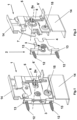
- a panel fitting part 1 for a drawer is shown, the view being directed towards the fastening side facing the side wall of the drawer.
- the panel fitting part 1 has angled areas 14 for easy connection to the side part of the drawer, with the connection being secured by means of screws, rivets, latchable or pressable bolts, etc.
- a panel assembly part 2 connected to the panel fitting part 1 is screwed to the back of the panel via bores 13 in the assembly part 2 and corresponding screws 12 or bolt connections that can be locked in place.
- a locking bolt 3 of the panel mounting part 2 connects it to the locking means 7 of the panel fitting part 1 at a predetermined distance from the back of the panel.
- the fascia of the drawer carries two such fascia mounting parts 2, connected to respective fascia fittings 1, at a distance adapted to the dimension of the outer sides of the two side walls of the open front of the drawer.
- the 1 also shows two legs of a fork 4 of the panel mounting part 2, which is directed towards the panel fitting part 1 and which encloses an adjusting body 5 designed as an eccentric bolt.
- an adjusting body 5 designed as an eccentric bolt.
- the position of the fork 4 can be pivoted about the locking bolt 3 and the inclination of the aperture can thus be changed, for example by means of a Phillips screwdriver.
- a trigger element 6 is shown, which when actuated in not shown, but in the DE 20 2014 002 229 U1 way shown, the two parts 1, 2 separates.
- This triggering element 6 can be designed with a fold-out actuating part 6'.
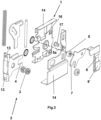
- the 2 shows the locking bolt 3, which is preferably rotatable and/or horizontally displaceable, which engages in a locking means 7 of the panel fitting part 1.
- an adjusting element 15 designed as an eccentric bolt, which is mounted in a corresponding opening of the aperture fitting part 1 and is connected to a movable part of the aperture fitting part, the aperture mounting part 2 and thus the aperture relative to the aperture fitting part 1 can be adjusted vertically.
- the visor assembly part 2 can be adjusted horizontally relative to the visor fitting part 1, with the locking bolt 3 having a smaller diameter in its inner area and a larger diameter in its two outer areas and the inward contact surfaces of the outer areas are in operative connection with the receiving fixing means 7 of the panel fitting part 1 or with the panel fitting part 1 and bring about the horizontal adjustment.
- the one in the is for tall drawers figures 6 , 7 and 8th embodiment shown advantageous.
- the aperture according to Figures 6 to 8 carries aligned panel assembly parts 2', 2" for each side part/frame and the side walls of the drawer on its rear side, each of which accommodates panel assembly parts 2 ⁇ , 2", panel fitting parts 1', which are secured by means of fixing means 7', 7" of the panel - hardware 1' and locking bolts 3', 3" of the panel mounting parts 2', 2" are operatively connectable.
- Each panel hardware is therefore connected to at least 2 assembly parts 2', 2".
- the panel assembly parts 2, 2' and the panel fitting parts 1' have means 4', 4", 8 for adjusting the inclination of the panel, which are connected to adjustment bodies 5 ⁇ of the panel -Fittings 1 'are in operative connection.
- the actuating part 6' or the triggering element 6 operatively connected to the actuating part 6', can be actuated, whereby the locking means 7', 7" are separated from the bolts 3', 3". .
- any number of locking means and corresponding assembly parts 2, 2' can be provided on each of the panel fitting parts 1, 1'.
- the individual fixing means can be released independently of one another in each of these embodiments.
- figure 9 shows an embodiment of the fitting part 1, 1' according to the invention, which is designed with two locking means 7', 7", with the individual locking means each being operatively connected to a release element 18, 19. These can be actuated separately from one another, with a release element 18, 19 one of the locking means is released from its connection with the respective bolt
- the two triggering elements 18, 19 are shown in different states.
- figure 9 II shows the two triggering elements 18, 19 in a first position, in which both locking means 7', 7'' are closed.
- figure 9 III shows the triggering element 18 in a position in relation to its first position according to FIG figure 9 II downward deflected second position, whereby the upper locking means 7" is opened.
- figure 9 III The corresponding movement of the individual parts is indicated by the two arrows in figure 9 III shown. According to figure 9 III remains with the movement of the readout release element 18 shown there According to triggering element 19 in its first position figure 9 II, wherein the lower locking means 7 'in its closed state according to figure 9 II remains.
- figure 9 IV remains the triggering element 18 in one of its first position according to figure 9 II, wherein the trigger element 19 is displaced downwards to a second position.
- This shift opens the lower locking means 7'.
- the two movements of the triggering element 19 and the locking means 7' which are related to one another are figure 9 IV illustrated arrows illustrated. In principle, however, the two triggering elements 18, 19 can be actuated independently of one another at the same time.
- the locking means 7', 7" for its movement between an open and a closed position does not have an axis of rotation with a fixed reference system, but rather is realized with a guide part, within which a displacement of the locking means 7', 7" is effected by translation.
- a projection 20 can be provided above each locking means 7', 7", which prevents the locking means 7', 7" from being displaceable from a closed to an open position simply by rotating the locking means 7', 7" around the connecting element 17. According to the invention, there can therefore be a safeguard, preferably in the form of the projection 20, which only allows the movement of the locking means 7', 7" from a closed to an open position if a translation of the connecting element 17 on the locking means 7', 7" from a rear or retracted position along the guide part/slot 16 to a front position of the guide part/slot 16. The front position can hereby face the panel of the drawer.
- An open position of a locking means 7', 7" can be present in particular when a bolt 3', 3" can be removed from a receiving area of the locking means 7', 7" and thus a connection between the panel fitting part 1' and the panel assembly part 2', 2" is detachable.
- Figure 9 I shows the release elements 18 and 19 in relation to the screen fitting part 1 'in an exploded view.
- the triggering elements 18 and 19 can each serve as a rail-like guide for the other triggering element, whereby actuation of the two triggering elements 18, 19 is made possible in a lower region of the panel fitting part 1'.
- an actuating part 6' can be provided on the respective triggering element 18, 19, which can preferably be folded out.
- figure 10 shows an embodiment of the panel fitting part 1' according to the invention, in which a decoupled opening movement between the two locking means 7', 7'' can be effected by means of a uniform release element 6.
- figure 10 I shows the embodiment in an exploded view with a trigger element 6, on which an engagement 21 is provided in a spring 22, the spring 22 on the lower locking means 7' can act directly or indirectly to open the locking means.
- An opening 23 is arranged in an upper area of the triggering element 6, which is connected to an actuating element for opening the upper fixing means 7''.
- stepwise actuation of the triggering element 6 first the lower locking means 7' can be opened one after the other by moving the triggering element 6 downwards into a first position and then the upper locking means 7" can be opened by moving the triggering element 6 further into a second position, which is preferably even further down than the first position from a starting position as shown in figure 10 II is shown to be opened.
- the respective movement of the triggering element 6 and the resulting opening of the individual locking means 7 ', 7 "in succession is in the figures 10 III to V represented by the arrows on the triggering elements 6 and the locking means 7', 7".
- the means for adjusting the inclination comprise an elongate guide plate 8 arranged vertically on the panel fitting part 1', the end 9' of the guide plate 8 and the adjusting body 5' alternating on end contact surfaces 4 ⁇ , 4" of the panel mounting part 2' and a can be placed over this additional screen assembly part 2" arranged thereon and one end of the guide plate 8 is connected to an adjustment body 5'.
- the guide plate 8 is provided with a slot 10 in the middle, in which a slide bolt 11 slides.
- the adjusting body 5' is guided through a recess in the guide plate 8 at one end 9 and is mounted in the visor fitting part 1', with the adjusting body 5' also acting as an effective surface for generating the displacement force on the end contact surface 4' of the visor mounting part 2'.
- the guide plate 8 also has at its other end 9' a part bent by 90°, which also serves as an effective surface for generating the displacement force on the end contact surface 4" of the screen assembly part 2".
- the axis 5a, 5a' of the adjustment body and the pivoting axis of the panel run parallel to the bottom or top side of the drawer and the panel can be pivoted by an angle of up to +/- 5 degrees for optimal adjustment and alignment with the cabinet body.
Landscapes
- Connection Of Plates (AREA)
- Drawers Of Furniture (AREA)
Claims (9)
- Console de fixation pour la fixation d'un diaphragme à un tiroir où la console de fixation se compose de pièces de ferrure de diaphragme (1,1`) pour le montage sur des parois latérales du tiroir ainsi que de pièces de montage du tiroir (2,2`, 2") pour le montage du verso du tiroir où les pièces de montage du tiroir (1, 1') sont absorbées par des pièces de montage du tiroir (2,2',2") où ces dernières sont connectables grâce à des moyens de blocage (7, 7', 7") des pièces de ferrure du tiroir (1, 1') et de boulons de blocage (3, 3', 3") des pièces de montage du tiroir (2, 2) où chacune des pièces de montage du tiroir (2, 2', 2") présente davantage de moyens (4, 4', 4") pour le réglage d'inclinaison du tiroir se trouvant respectivement en liaison fonctionnelle avec son montage mâle (5, 5`) formé en boulon excentrique des pièces de ferrure du tiroir (1, 1') et le tiroir pivote autour d'un axe étendu parallèlement au côté inférieur et à la face de recouvrement du tiroir et où les moyens de blocage (7`, 7") sont disposés respectivement sur une partie de guidage à titre coulissant et sont mobiles tout au long de la partie de guidage entre une position ouverte des moyens de blocage (7`, 7") et une position fermée des moyens de blocage (7`, 7") est caractérisée de sorte que soit les moyens pour le réglage d'inclinaison comporte une fourche (4) orientée vers la pièce de ferrure du tiroir de la pièce de montage du tiroir (2) absorbant le boulon excentrique (5) et que les moyens pour le réglage d'inclinaison comportent un déflecteur oblong (8) disposé verticalement sur la pièce de ferrure du tiroir (1) où le boulon excentrique (5) ou le cas échéant l'extrémité (9) du déflecteur (8) sont appliqués alternativement sur les surfaces terminales (4`, 4") de la pièce de montage du tiroir (2) et d'une pièce de montage du tiroir (2) supplémentaire disposée sur elle et où une deuxième extrémité (9) du déflecteur (8) se trouve en liaison avec le boulon excentrique (5).
- Console de fixation selon l'une des revendications précédentes est caractérisée de sorte que l'axe (5a, 5a`) du boulon excentrique (5, 5`) et l'axe de pivotement du tiroir s'étendent parallèlement.
- Console de fixation selon l'une des revendications précédentes est caractérisée de sorte que le tiroir est pivotant d'un angle de jusqu'à +/- 5 grade.
- Console de fixation selon l'une des revendications précédentes est caractérisée de sorte que le boulon excentrique (5`) est conduit par le biais de l'évidement du déflecteur (8) à son extrémité (9) et est stocké dans la pièce de ferrure du tiroir (1') et que le déflecteur (8) présente à son extrémité (9') une pièce inclinée autour du 90°.
- Console de fixation selon l'une des revendications précédentes est caractérisée de sorte que la pièce de montage du tiroir (2, 2', 2") est relativement et verticalement ajustable en rapport avec la pièce de ferrure du tiroir (1, 1').
- Console de fixation selon l'une des revendications précédentes est caractérisée de sorte que la pièce de montage du tiroir (2, 2', 2") est relativement et horizontalement ajustable en rapport avec la pièce de ferrure du tiroir (1, 1').
- Console de fixation selon l'une des revendications précédentes est caractérisée de sorte qu'au minimum un élément déclencheur (6) est prévu pour le déclenchement de la liaison entre les moyens de blocage (7, 7', 7") et la pièce de montage du tiroir (2, 2', 2") sur la pièce de ferrure du tiroir (1, 1').
- Console de fixation selon l'une des revendications précédentes est caractérisée de sorte que la pièce de ferrure du tiroir (1 ') présente au minimum deux moyens de blocage (7`, 7") où les différents moyens de blocage sont amovibles par le biais d'éléments de déclenchements particuliers.
- Console de fixation selon l'une des revendications précédentes est caractérisée de sorte que les connexions entre au minimum deux pièces de montage du tiroir (2', 2") et les moyens de blocage respectifs (7`, 7") de la pièce de ferrure du tiroir (1 ') sont amovibles après l'actionnement de chaque élément de déclenchement (6) sur une pièce de ferrure du tiroir (1') où un dispositif de découplage se trouve en liaison active avec l'élément de déclenchement (6) et est formé pour déclencher les différentes connexions les unes les autres retardement ou le cas échéant avec un décalage temporel entre les moyens de blocage (7',7") et les pièces de montage du tiroir (2', 2").
Applications Claiming Priority (2)
| Application Number | Priority Date | Filing Date | Title |
|---|---|---|---|
| EP17170432 | 2017-05-10 | ||
| PCT/EP2018/062145 WO2018206727A1 (fr) | 2017-05-10 | 2018-05-09 | Ferrure de fixation pour une façade |
Publications (2)
| Publication Number | Publication Date |
|---|---|
| EP3621485A1 EP3621485A1 (fr) | 2020-03-18 |
| EP3621485B1 true EP3621485B1 (fr) | 2023-02-08 |
Family
ID=58707314
Family Applications (1)
| Application Number | Title | Priority Date | Filing Date |
|---|---|---|---|
| EP18724522.0A Active EP3621485B1 (fr) | 2017-05-10 | 2018-05-09 | Ferrure de fixation pour une façade de tiroir |
Country Status (4)
| Country | Link |
|---|---|
| US (1) | US11071381B2 (fr) |
| EP (1) | EP3621485B1 (fr) |
| CN (1) | CN110730621B (fr) |
| WO (1) | WO2018206727A1 (fr) |
Families Citing this family (3)
| Publication number | Priority date | Publication date | Assignee | Title |
|---|---|---|---|---|
| AT521512B1 (de) * | 2018-10-05 | 2020-02-15 | Blum Gmbh Julius | Befestigungsvorrichtung zum lösbaren Befestigen einer Frontblende an einer Schublade |
| AT17224U1 (de) * | 2020-05-15 | 2021-09-15 | Van Hoecke Nv | Anordnung aus einer Schubladenseitenwand und einer Verbindungsvorrichtung |
| CN116268827B (zh) * | 2023-04-15 | 2026-02-27 | 广东东泰五金精密制造有限公司 | 一种具有调节机构的抽屉组件 |
Family Cites Families (26)
| Publication number | Priority date | Publication date | Assignee | Title |
|---|---|---|---|---|
| AT393203B (de) * | 1987-12-07 | 1991-09-10 | Alfit Gmbh | Schublade mit auszugsgarnitur |
| AT398514B (de) * | 1990-07-12 | 1994-12-27 | Alfit Ag | Schublade mit metallischen zargen |
| DE19944639A1 (de) * | 1999-09-17 | 2001-03-22 | Hettich Paul Gmbh & Co | Befestigungsanordnung |
| DE19944642A1 (de) * | 1999-09-17 | 2001-03-22 | Hettich Paul Gmbh & Co | Befestigungsvorrichtung |
| DE102009025890A1 (de) | 2009-05-29 | 2011-06-22 | Paul Hettich GmbH & Co. KG, 32278 | Vorrichtung zur Befestigung einer Frontblende an einer Seitenzarge eines beweglichen Möbelteils eines Möbels, Schubkasten und Möbel |
| AT509411B1 (de) * | 2010-02-03 | 2012-05-15 | Blum Gmbh Julius | Schubladenzarge |
| CN102058253B (zh) * | 2010-10-27 | 2012-12-26 | 东莞世巨五金塑胶制品有限公司 | 抽屉面板角度调整结构 |
| AT510779B1 (de) * | 2010-11-23 | 2014-09-15 | Blum Gmbh Julius | Möbelbeschlag zur frontblendenbefestigung |
| AT511294B1 (de) * | 2011-04-11 | 2013-06-15 | Blum Gmbh Julius | Schubladenausziehführung |
| AT511066B1 (de) * | 2011-05-24 | 2012-09-15 | Blum Gmbh Julius | Befestigungsvorrichtung zum befestigen einer frontblende an einer schublade |
| AT511538B1 (de) * | 2011-05-24 | 2013-06-15 | Blum Gmbh Julius | Befestigungsvorrichtung zum befestigen einer frontblende an einer schublade |
| AT510954B1 (de) * | 2011-05-24 | 2012-08-15 | Blum Gmbh Julius | Rastgesperre für möbelstücke |
| US8585166B2 (en) * | 2011-07-14 | 2013-11-19 | King Slide Works Co., Ltd. | Slide assembly and connection device |
| AT512236B1 (de) * | 2011-11-22 | 2015-10-15 | Blum Gmbh Julius | Befestigungsvorrichtung zum befestigen einer frontblende an einer schublade |
| CN203302661U (zh) * | 2013-04-23 | 2013-11-27 | 广东泰明金属制品有限公司 | 抽屉面板调节装置 |
| DE202014002229U1 (de) | 2014-03-14 | 2014-04-29 | Erwin Krüger | Befestigungsbeschlag für eine Blende an einer offenen Stirnseite einer Schublade |
| US9185976B2 (en) * | 2014-04-08 | 2015-11-17 | King Slide Works Co., Ltd. | Adjusting device |
| DE102014011090A1 (de) * | 2014-07-30 | 2016-02-04 | Erwin Krüger | Befestigungsbeschlag für eine Blende an einer offenen Stirnseite einer Schublade |
| DE102014113954B4 (de) * | 2014-09-26 | 2022-07-14 | Samet Kalip Ve Maden Esya San. Ve Tic. A.S. | Verstelleinrichtung |
| CN204232569U (zh) * | 2014-10-07 | 2015-04-01 | 宿州学院 | 一种多功能学生课桌 |
| AT516838B1 (de) * | 2015-03-13 | 2016-09-15 | Blum Gmbh Julius | Befestigungsvorrichtung zum lösbaren Befestigen einer Frontblende an einer Schublade |
| CN107809927A (zh) * | 2015-06-15 | 2018-03-16 | 形橙产品开发公司 | 具有底板、两个侧壁、后壁以及挡板的抽屉 |
| TWI548371B (zh) * | 2015-11-12 | 2016-09-11 | 川湖科技股份有限公司 | 抽屜滑軌組件及其安裝裝置 |
| US10010174B2 (en) * | 2015-11-12 | 2018-07-03 | King Slide Works Co., Ltd. | Mounting mechanism |
| US9752817B2 (en) * | 2015-12-18 | 2017-09-05 | Whirlpool Corporation | Door/drawer panel adjustment mechanism for an appliance |
| CN108433407A (zh) * | 2017-02-16 | 2018-08-24 | 苏树鹏 | 抽屉面板调整装置 |
-
2018
- 2018-05-09 US US16/611,108 patent/US11071381B2/en active Active
- 2018-05-09 EP EP18724522.0A patent/EP3621485B1/fr active Active
- 2018-05-09 CN CN201880038433.2A patent/CN110730621B/zh active Active
- 2018-05-09 WO PCT/EP2018/062145 patent/WO2018206727A1/fr not_active Ceased
Also Published As
| Publication number | Publication date |
|---|---|
| US11071381B2 (en) | 2021-07-27 |
| CN110730621A (zh) | 2020-01-24 |
| EP3621485A1 (fr) | 2020-03-18 |
| WO2018206727A1 (fr) | 2018-11-15 |
| CN110730621B (zh) | 2021-11-02 |
| US20200054132A1 (en) | 2020-02-20 |
Similar Documents
| Publication | Publication Date | Title |
|---|---|---|
| AT515425B1 (de) | Vorrichtung zur befestigung einer frontblende an einer seitenzarge eines beweglichen möbelteils eines möbels, schubkasten und möbel | |
| EP3542672B1 (fr) | Ferrure de meuble destinée au montage du panneau avant | |
| EP2531065B1 (fr) | Châssis de tiroir | |
| EP2294957B1 (fr) | Dispositif de retenue d'éléments plats | |
| EP3625417B1 (fr) | Bras de commande réglable en longueur | |
| EP3088645B1 (fr) | Dispositif de liaison pour une porte coulissante | |
| EP3621485B1 (fr) | Ferrure de fixation pour une façade de tiroir | |
| EP3621483B1 (fr) | Dispositif de retenue pour façade de tiroir | |
| EP1605796B1 (fr) | Tiroir | |
| DE202004012298U1 (de) | Haushaltsgerät mit verschwenkbarem Anzeigeschirm | |
| EP4225104B1 (fr) | Dispositif pour fixer un panneau avant sur un cadre latéral d'un tiroir | |
| DE102012100974B4 (de) | Lüfter und Anordnung aufweisend einen derartigen Lüfter | |
| EP3621484A2 (fr) | Dispositif de retenue pour façade de tiroir | |
| EP3704337B1 (fr) | Pièce de bande | |
| EP3009043B1 (fr) | Tiroir coulissant avec un dispositif de reglage pour l'alignement du panneau frontal | |
| EP3666120B1 (fr) | Dispositif de raccordement de l'avant de tiroir et tiroir | |
| EP3737262B1 (fr) | Dispositif constitué par une glissière télescopique et un entraîneur | |
| WO2008000320A1 (fr) | Penture de portes, fenêtres ou similaires | |
| WO2025255591A1 (fr) | Dispositif de montage pour fixer amovible un panneau avant à un tiroir | |
| DE102024207145A1 (de) | Frontblendenbeschlag | |
| EP3860402A1 (fr) | Dispositif de fixation servant à fixer un panneau d'un tiroir sur un châssis | |
| WO2021233776A1 (fr) | Dispositif de réception de récipient et son support | |
| EP1936063A2 (fr) | Mécanisme de réglage pour une marquise | |
| DE202005013245U1 (de) | Scheinwerfer |
Legal Events
| Date | Code | Title | Description |
|---|---|---|---|
| STAA | Information on the status of an ep patent application or granted ep patent |
Free format text: STATUS: UNKNOWN |
|
| STAA | Information on the status of an ep patent application or granted ep patent |
Free format text: STATUS: THE INTERNATIONAL PUBLICATION HAS BEEN MADE |
|
| PUAI | Public reference made under article 153(3) epc to a published international application that has entered the european phase |
Free format text: ORIGINAL CODE: 0009012 |
|
| STAA | Information on the status of an ep patent application or granted ep patent |
Free format text: STATUS: REQUEST FOR EXAMINATION WAS MADE |
|
| 17P | Request for examination filed |
Effective date: 20191210 |
|
| AK | Designated contracting states |
Kind code of ref document: A1 Designated state(s): AL AT BE BG CH CY CZ DE DK EE ES FI FR GB GR HR HU IE IS IT LI LT LU LV MC MK MT NL NO PL PT RO RS SE SI SK SM TR |
|
| AX | Request for extension of the european patent |
Extension state: BA ME |
|
| DAV | Request for validation of the european patent (deleted) | ||
| DAX | Request for extension of the european patent (deleted) | ||
| STAA | Information on the status of an ep patent application or granted ep patent |
Free format text: STATUS: EXAMINATION IS IN PROGRESS |
|
| 17Q | First examination report despatched |
Effective date: 20210203 |
|
| GRAP | Despatch of communication of intention to grant a patent |
Free format text: ORIGINAL CODE: EPIDOSNIGR1 |
|
| STAA | Information on the status of an ep patent application or granted ep patent |
Free format text: STATUS: GRANT OF PATENT IS INTENDED |
|
| INTG | Intention to grant announced |
Effective date: 20220826 |
|
| GRAS | Grant fee paid |
Free format text: ORIGINAL CODE: EPIDOSNIGR3 |
|
| GRAA | (expected) grant |
Free format text: ORIGINAL CODE: 0009210 |
|
| STAA | Information on the status of an ep patent application or granted ep patent |
Free format text: STATUS: THE PATENT HAS BEEN GRANTED |
|
| AK | Designated contracting states |
Kind code of ref document: B1 Designated state(s): AL AT BE BG CH CY CZ DE DK EE ES FI FR GB GR HR HU IE IS IT LI LT LU LV MC MK MT NL NO PL PT RO RS SE SI SK SM TR |
|
| REG | Reference to a national code |
Ref country code: GB Ref legal event code: FG4D Free format text: NOT ENGLISH |
|
| REG | Reference to a national code |
Ref country code: CH Ref legal event code: EP Ref country code: AT Ref legal event code: REF Ref document number: 1547279 Country of ref document: AT Kind code of ref document: T Effective date: 20230215 |
|
| REG | Reference to a national code |
Ref country code: IE Ref legal event code: FG4D Free format text: LANGUAGE OF EP DOCUMENT: GERMAN |
|
| REG | Reference to a national code |
Ref country code: DE Ref legal event code: R096 Ref document number: 502018011561 Country of ref document: DE |
|
| REG | Reference to a national code |
Ref country code: LT Ref legal event code: MG9D |
|
| REG | Reference to a national code |
Ref country code: NL Ref legal event code: MP Effective date: 20230208 |
|
| PG25 | Lapsed in a contracting state [announced via postgrant information from national office to epo] |
Ref country code: RS Free format text: LAPSE BECAUSE OF FAILURE TO SUBMIT A TRANSLATION OF THE DESCRIPTION OR TO PAY THE FEE WITHIN THE PRESCRIBED TIME-LIMIT Effective date: 20230208 Ref country code: PT Free format text: LAPSE BECAUSE OF FAILURE TO SUBMIT A TRANSLATION OF THE DESCRIPTION OR TO PAY THE FEE WITHIN THE PRESCRIBED TIME-LIMIT Effective date: 20230609 Ref country code: NO Free format text: LAPSE BECAUSE OF FAILURE TO SUBMIT A TRANSLATION OF THE DESCRIPTION OR TO PAY THE FEE WITHIN THE PRESCRIBED TIME-LIMIT Effective date: 20230508 Ref country code: NL Free format text: LAPSE BECAUSE OF FAILURE TO SUBMIT A TRANSLATION OF THE DESCRIPTION OR TO PAY THE FEE WITHIN THE PRESCRIBED TIME-LIMIT Effective date: 20230208 Ref country code: LV Free format text: LAPSE BECAUSE OF FAILURE TO SUBMIT A TRANSLATION OF THE DESCRIPTION OR TO PAY THE FEE WITHIN THE PRESCRIBED TIME-LIMIT Effective date: 20230208 Ref country code: LT Free format text: LAPSE BECAUSE OF FAILURE TO SUBMIT A TRANSLATION OF THE DESCRIPTION OR TO PAY THE FEE WITHIN THE PRESCRIBED TIME-LIMIT Effective date: 20230208 Ref country code: HR Free format text: LAPSE BECAUSE OF FAILURE TO SUBMIT A TRANSLATION OF THE DESCRIPTION OR TO PAY THE FEE WITHIN THE PRESCRIBED TIME-LIMIT Effective date: 20230208 Ref country code: ES Free format text: LAPSE BECAUSE OF FAILURE TO SUBMIT A TRANSLATION OF THE DESCRIPTION OR TO PAY THE FEE WITHIN THE PRESCRIBED TIME-LIMIT Effective date: 20230208 |
|
| PG25 | Lapsed in a contracting state [announced via postgrant information from national office to epo] |
Ref country code: SE Free format text: LAPSE BECAUSE OF FAILURE TO SUBMIT A TRANSLATION OF THE DESCRIPTION OR TO PAY THE FEE WITHIN THE PRESCRIBED TIME-LIMIT Effective date: 20230208 Ref country code: PL Free format text: LAPSE BECAUSE OF FAILURE TO SUBMIT A TRANSLATION OF THE DESCRIPTION OR TO PAY THE FEE WITHIN THE PRESCRIBED TIME-LIMIT Effective date: 20230208 Ref country code: IS Free format text: LAPSE BECAUSE OF FAILURE TO SUBMIT A TRANSLATION OF THE DESCRIPTION OR TO PAY THE FEE WITHIN THE PRESCRIBED TIME-LIMIT Effective date: 20230608 Ref country code: GR Free format text: LAPSE BECAUSE OF FAILURE TO SUBMIT A TRANSLATION OF THE DESCRIPTION OR TO PAY THE FEE WITHIN THE PRESCRIBED TIME-LIMIT Effective date: 20230509 Ref country code: FI Free format text: LAPSE BECAUSE OF FAILURE TO SUBMIT A TRANSLATION OF THE DESCRIPTION OR TO PAY THE FEE WITHIN THE PRESCRIBED TIME-LIMIT Effective date: 20230208 |
|
| PG25 | Lapsed in a contracting state [announced via postgrant information from national office to epo] |
Ref country code: SM Free format text: LAPSE BECAUSE OF FAILURE TO SUBMIT A TRANSLATION OF THE DESCRIPTION OR TO PAY THE FEE WITHIN THE PRESCRIBED TIME-LIMIT Effective date: 20230208 Ref country code: RO Free format text: LAPSE BECAUSE OF FAILURE TO SUBMIT A TRANSLATION OF THE DESCRIPTION OR TO PAY THE FEE WITHIN THE PRESCRIBED TIME-LIMIT Effective date: 20230208 Ref country code: EE Free format text: LAPSE BECAUSE OF FAILURE TO SUBMIT A TRANSLATION OF THE DESCRIPTION OR TO PAY THE FEE WITHIN THE PRESCRIBED TIME-LIMIT Effective date: 20230208 Ref country code: DK Free format text: LAPSE BECAUSE OF FAILURE TO SUBMIT A TRANSLATION OF THE DESCRIPTION OR TO PAY THE FEE WITHIN THE PRESCRIBED TIME-LIMIT Effective date: 20230208 Ref country code: CZ Free format text: LAPSE BECAUSE OF FAILURE TO SUBMIT A TRANSLATION OF THE DESCRIPTION OR TO PAY THE FEE WITHIN THE PRESCRIBED TIME-LIMIT Effective date: 20230208 |
|
| REG | Reference to a national code |
Ref country code: DE Ref legal event code: R097 Ref document number: 502018011561 Country of ref document: DE |
|
| PG25 | Lapsed in a contracting state [announced via postgrant information from national office to epo] |
Ref country code: SK Free format text: LAPSE BECAUSE OF FAILURE TO SUBMIT A TRANSLATION OF THE DESCRIPTION OR TO PAY THE FEE WITHIN THE PRESCRIBED TIME-LIMIT Effective date: 20230208 |
|
| PLBE | No opposition filed within time limit |
Free format text: ORIGINAL CODE: 0009261 |
|
| STAA | Information on the status of an ep patent application or granted ep patent |
Free format text: STATUS: NO OPPOSITION FILED WITHIN TIME LIMIT |
|
| REG | Reference to a national code |
Ref country code: CH Ref legal event code: PL |
|
| 26N | No opposition filed |
Effective date: 20231109 |
|
| PG25 | Lapsed in a contracting state [announced via postgrant information from national office to epo] |
Ref country code: MC Free format text: LAPSE BECAUSE OF FAILURE TO SUBMIT A TRANSLATION OF THE DESCRIPTION OR TO PAY THE FEE WITHIN THE PRESCRIBED TIME-LIMIT Effective date: 20230208 |
|
| GBPC | Gb: european patent ceased through non-payment of renewal fee |
Effective date: 20230509 |
|
| REG | Reference to a national code |
Ref country code: BE Ref legal event code: MM Effective date: 20230531 |
|
| PG25 | Lapsed in a contracting state [announced via postgrant information from national office to epo] |
Ref country code: SI Free format text: LAPSE BECAUSE OF FAILURE TO SUBMIT A TRANSLATION OF THE DESCRIPTION OR TO PAY THE FEE WITHIN THE PRESCRIBED TIME-LIMIT Effective date: 20230208 Ref country code: MC Free format text: LAPSE BECAUSE OF FAILURE TO SUBMIT A TRANSLATION OF THE DESCRIPTION OR TO PAY THE FEE WITHIN THE PRESCRIBED TIME-LIMIT Effective date: 20230208 Ref country code: LU Free format text: LAPSE BECAUSE OF NON-PAYMENT OF DUE FEES Effective date: 20230509 Ref country code: LI Free format text: LAPSE BECAUSE OF NON-PAYMENT OF DUE FEES Effective date: 20230531 Ref country code: CH Free format text: LAPSE BECAUSE OF NON-PAYMENT OF DUE FEES Effective date: 20230531 |
|
| REG | Reference to a national code |
Ref country code: IE Ref legal event code: MM4A |
|
| PG25 | Lapsed in a contracting state [announced via postgrant information from national office to epo] |
Ref country code: IE Free format text: LAPSE BECAUSE OF NON-PAYMENT OF DUE FEES Effective date: 20230509 |
|
| PG25 | Lapsed in a contracting state [announced via postgrant information from national office to epo] |
Ref country code: IE Free format text: LAPSE BECAUSE OF NON-PAYMENT OF DUE FEES Effective date: 20230509 Ref country code: GB Free format text: LAPSE BECAUSE OF NON-PAYMENT OF DUE FEES Effective date: 20230509 |
|
| PG25 | Lapsed in a contracting state [announced via postgrant information from national office to epo] |
Ref country code: FR Free format text: LAPSE BECAUSE OF NON-PAYMENT OF DUE FEES Effective date: 20230531 Ref country code: BE Free format text: LAPSE BECAUSE OF NON-PAYMENT OF DUE FEES Effective date: 20230531 |
|
| PG25 | Lapsed in a contracting state [announced via postgrant information from national office to epo] |
Ref country code: BG Free format text: LAPSE BECAUSE OF FAILURE TO SUBMIT A TRANSLATION OF THE DESCRIPTION OR TO PAY THE FEE WITHIN THE PRESCRIBED TIME-LIMIT Effective date: 20230208 |
|
| PG25 | Lapsed in a contracting state [announced via postgrant information from national office to epo] |
Ref country code: BG Free format text: LAPSE BECAUSE OF FAILURE TO SUBMIT A TRANSLATION OF THE DESCRIPTION OR TO PAY THE FEE WITHIN THE PRESCRIBED TIME-LIMIT Effective date: 20230208 |
|
| PGFP | Annual fee paid to national office [announced via postgrant information from national office to epo] |
Ref country code: DE Payment date: 20250530 Year of fee payment: 8 |
|
| PGFP | Annual fee paid to national office [announced via postgrant information from national office to epo] |
Ref country code: IT Payment date: 20250530 Year of fee payment: 8 |
|
| PGFP | Annual fee paid to national office [announced via postgrant information from national office to epo] |
Ref country code: AT Payment date: 20250602 Year of fee payment: 8 |
|
| PG25 | Lapsed in a contracting state [announced via postgrant information from national office to epo] |
Ref country code: CY Free format text: LAPSE BECAUSE OF FAILURE TO SUBMIT A TRANSLATION OF THE DESCRIPTION OR TO PAY THE FEE WITHIN THE PRESCRIBED TIME-LIMIT; INVALID AB INITIO Effective date: 20180509 |
|
| PG25 | Lapsed in a contracting state [announced via postgrant information from national office to epo] |
Ref country code: HU Free format text: LAPSE BECAUSE OF FAILURE TO SUBMIT A TRANSLATION OF THE DESCRIPTION OR TO PAY THE FEE WITHIN THE PRESCRIBED TIME-LIMIT; INVALID AB INITIO Effective date: 20180509 |
|
| PG25 | Lapsed in a contracting state [announced via postgrant information from national office to epo] |
Ref country code: TR Free format text: LAPSE BECAUSE OF FAILURE TO SUBMIT A TRANSLATION OF THE DESCRIPTION OR TO PAY THE FEE WITHIN THE PRESCRIBED TIME-LIMIT Effective date: 20230208 |