EP3621669B1 - Interconnexion thermique pour pompe à sang implantable - Google Patents
Interconnexion thermique pour pompe à sang implantable Download PDFInfo
- Publication number
- EP3621669B1 EP3621669B1 EP18727621.7A EP18727621A EP3621669B1 EP 3621669 B1 EP3621669 B1 EP 3621669B1 EP 18727621 A EP18727621 A EP 18727621A EP 3621669 B1 EP3621669 B1 EP 3621669B1
- Authority
- EP
- European Patent Office
- Prior art keywords
- blood pump
- blood
- thermal
- pump
- magnetic core
- Prior art date
- Legal status (The legal status is an assumption and is not a legal conclusion. Google has not performed a legal analysis and makes no representation as to the accuracy of the status listed.)
- Active
Links
Images






Classifications
-
- A—HUMAN NECESSITIES
- A61—MEDICAL OR VETERINARY SCIENCE; HYGIENE
- A61M—DEVICES FOR INTRODUCING MEDIA INTO, OR ONTO, THE BODY; DEVICES FOR TRANSDUCING BODY MEDIA OR FOR TAKING MEDIA FROM THE BODY; DEVICES FOR PRODUCING OR ENDING SLEEP OR STUPOR
- A61M60/00—Blood pumps; Devices for mechanical circulatory actuation; Balloon pumps for circulatory assistance
- A61M60/10—Location thereof with respect to the patient's body
- A61M60/122—Implantable pumps or pumping devices, i.e. the blood being pumped inside the patient's body
- A61M60/126—Implantable pumps or pumping devices, i.e. the blood being pumped inside the patient's body implantable via, into, inside, in line, branching on, or around a blood vessel
- A61M60/148—Implantable pumps or pumping devices, i.e. the blood being pumped inside the patient's body implantable via, into, inside, in line, branching on, or around a blood vessel in line with a blood vessel using resection or like techniques, e.g. permanent endovascular heart assist devices
-
- A—HUMAN NECESSITIES
- A61—MEDICAL OR VETERINARY SCIENCE; HYGIENE
- A61M—DEVICES FOR INTRODUCING MEDIA INTO, OR ONTO, THE BODY; DEVICES FOR TRANSDUCING BODY MEDIA OR FOR TAKING MEDIA FROM THE BODY; DEVICES FOR PRODUCING OR ENDING SLEEP OR STUPOR
- A61M60/00—Blood pumps; Devices for mechanical circulatory actuation; Balloon pumps for circulatory assistance
- A61M60/10—Location thereof with respect to the patient's body
- A61M60/122—Implantable pumps or pumping devices, i.e. the blood being pumped inside the patient's body
- A61M60/165—Implantable pumps or pumping devices, i.e. the blood being pumped inside the patient's body implantable in, on, or around the heart
- A61M60/178—Implantable pumps or pumping devices, i.e. the blood being pumped inside the patient's body implantable in, on, or around the heart drawing blood from a ventricle and returning the blood to the arterial system via a cannula external to the ventricle, e.g. left or right ventricular assist devices
-
- A—HUMAN NECESSITIES
- A61—MEDICAL OR VETERINARY SCIENCE; HYGIENE
- A61M—DEVICES FOR INTRODUCING MEDIA INTO, OR ONTO, THE BODY; DEVICES FOR TRANSDUCING BODY MEDIA OR FOR TAKING MEDIA FROM THE BODY; DEVICES FOR PRODUCING OR ENDING SLEEP OR STUPOR
- A61M60/00—Blood pumps; Devices for mechanical circulatory actuation; Balloon pumps for circulatory assistance
- A61M60/20—Type thereof
- A61M60/205—Non-positive displacement blood pumps
- A61M60/216—Non-positive displacement blood pumps including a rotating member acting on the blood, e.g. impeller
-
- A—HUMAN NECESSITIES
- A61—MEDICAL OR VETERINARY SCIENCE; HYGIENE
- A61M—DEVICES FOR INTRODUCING MEDIA INTO, OR ONTO, THE BODY; DEVICES FOR TRANSDUCING BODY MEDIA OR FOR TAKING MEDIA FROM THE BODY; DEVICES FOR PRODUCING OR ENDING SLEEP OR STUPOR
- A61M60/00—Blood pumps; Devices for mechanical circulatory actuation; Balloon pumps for circulatory assistance
- A61M60/40—Details relating to driving
- A61M60/403—Details relating to driving for non-positive displacement blood pumps
- A61M60/419—Details relating to driving for non-positive displacement blood pumps the force acting on the blood contacting member being permanent magnetic, e.g. from a rotating magnetic coupling between driving and driven magnets
-
- A—HUMAN NECESSITIES
- A61—MEDICAL OR VETERINARY SCIENCE; HYGIENE
- A61M—DEVICES FOR INTRODUCING MEDIA INTO, OR ONTO, THE BODY; DEVICES FOR TRANSDUCING BODY MEDIA OR FOR TAKING MEDIA FROM THE BODY; DEVICES FOR PRODUCING OR ENDING SLEEP OR STUPOR
- A61M60/00—Blood pumps; Devices for mechanical circulatory actuation; Balloon pumps for circulatory assistance
- A61M60/40—Details relating to driving
- A61M60/403—Details relating to driving for non-positive displacement blood pumps
- A61M60/422—Details relating to driving for non-positive displacement blood pumps the force acting on the blood contacting member being electromagnetic, e.g. using canned motor pumps
-
- A—HUMAN NECESSITIES
- A61—MEDICAL OR VETERINARY SCIENCE; HYGIENE
- A61M—DEVICES FOR INTRODUCING MEDIA INTO, OR ONTO, THE BODY; DEVICES FOR TRANSDUCING BODY MEDIA OR FOR TAKING MEDIA FROM THE BODY; DEVICES FOR PRODUCING OR ENDING SLEEP OR STUPOR
- A61M60/00—Blood pumps; Devices for mechanical circulatory actuation; Balloon pumps for circulatory assistance
- A61M60/50—Details relating to control
- A61M60/508—Electronic control means, e.g. for feedback regulation
-
- A—HUMAN NECESSITIES
- A61—MEDICAL OR VETERINARY SCIENCE; HYGIENE
- A61M—DEVICES FOR INTRODUCING MEDIA INTO, OR ONTO, THE BODY; DEVICES FOR TRANSDUCING BODY MEDIA OR FOR TAKING MEDIA FROM THE BODY; DEVICES FOR PRODUCING OR ENDING SLEEP OR STUPOR
- A61M60/00—Blood pumps; Devices for mechanical circulatory actuation; Balloon pumps for circulatory assistance
- A61M60/80—Constructional details other than related to driving
- A61M60/802—Constructional details other than related to driving of non-positive displacement blood pumps
- A61M60/81—Pump housings
-
- A—HUMAN NECESSITIES
- A61—MEDICAL OR VETERINARY SCIENCE; HYGIENE
- A61M—DEVICES FOR INTRODUCING MEDIA INTO, OR ONTO, THE BODY; DEVICES FOR TRANSDUCING BODY MEDIA OR FOR TAKING MEDIA FROM THE BODY; DEVICES FOR PRODUCING OR ENDING SLEEP OR STUPOR
- A61M2205/00—General characteristics of the apparatus
- A61M2205/33—Controlling, regulating or measuring
- A61M2205/3368—Temperature
- A61M2205/3372—Temperature compensation
-
- A—HUMAN NECESSITIES
- A61—MEDICAL OR VETERINARY SCIENCE; HYGIENE
- A61M—DEVICES FOR INTRODUCING MEDIA INTO, OR ONTO, THE BODY; DEVICES FOR TRANSDUCING BODY MEDIA OR FOR TAKING MEDIA FROM THE BODY; DEVICES FOR PRODUCING OR ENDING SLEEP OR STUPOR
- A61M2205/00—General characteristics of the apparatus
- A61M2205/36—General characteristics of the apparatus related to heating or cooling
-
- A—HUMAN NECESSITIES
- A61—MEDICAL OR VETERINARY SCIENCE; HYGIENE
- A61M—DEVICES FOR INTRODUCING MEDIA INTO, OR ONTO, THE BODY; DEVICES FOR TRANSDUCING BODY MEDIA OR FOR TAKING MEDIA FROM THE BODY; DEVICES FOR PRODUCING OR ENDING SLEEP OR STUPOR
- A61M2205/00—General characteristics of the apparatus
- A61M2205/36—General characteristics of the apparatus related to heating or cooling
- A61M2205/3606—General characteristics of the apparatus related to heating or cooling cooled
Definitions
- This application relates generally to mechanical circulatory support systems, and more specifically relates to control systems, for an implantable blood pump
- Ventricular assist devices are implantable blood pumps used for both short-term (i.e., days, months) and long-term applications (i.e., years or a lifetime) where a patient's heart is incapable of providing adequate circulation, commonly referred to as heart failure or congestive heart failure.
- heart failure congestive heart failure
- Most than five million Americans are living with heart failure, with about 670,000 new cases diagnosed every year. People with heart failure often have shortness of breath and fatigue. Years of living with blocked arteries or high blood pressure can leave your heart too weak to pump enough blood to your body. As symptoms worsen, advanced heart failure develops.
- a patient suffering from heart failure also called congestive heart failure (CHF)
- CHF congestive heart failure
- a patient may use a VAD while awaiting a heart transplant or as a long term destination therapy.
- a patient may use a VAD while recovering from heart surgery.
- a VAD can supplement a weak heart (i.e., partial support) or can effectively replace the natural heart's function.
- VADs can be implanted in the patient's body and powered by an electrical power source inside or outside the patient's body.
- US 2002/009363 A1 which shows all the features of the preamble of independent claim 1, discloses a fluid pump wherein in a casing at a pump unit there is provided an impeller coupled with a rotor contactless and also supported contactless by a controlled magnetic bearing unit, and rotated by a motor to output a fluid, with a position detection unit, an electromagnet or a motor stator cooled by a fluid flowing through a pump chamber.
- VADs Due to VAD workload in constantly pumping blood, VADs can have significantly higher power requirements than other types of implantable devices such as pacemakers or other stimulators. Because of these power requirements, VADs can be externally powered by delivering power from outside of a patient's body to the VAD inside of the patient's body. Further, because of these higher power requirements, VADs generate significant amounts of heat during operation.
- VAD therapy there remains a need to improve the therapy and design of VADs in particular.
- One aim for improving VADs is to provide smaller pumps with the same or better performance.
- a challenge with smaller pumps is management of heat generated in the pump.
- smaller pumps need to be designed to rotate the impeller at the same or even a higher rotational speed, yet they have a smaller surface area in contact with adjacent tissue. This can translate to greater localized heating which can lead to tissue damage. In certain cases regulatory requirements for such tissue heating can be a limiting factor on performance. Accordingly, further VAD improvements, and particularly improvements to heat management within VADs are desired.
- the present invention relates to an implantable blood pump as defined in claim 1.
- the dependent claims define preferred embodiments of the implantable blood pump.
- Embodiments of the present disclosure relate to devices, systems, and methods for efficiently managing heat within a ventricular assist system, and in certain respects an implantable blood pump. This can include the generation of a preferential conductive heat pathway connecting electronics within the blood pump to a portion of a blood conduit extending through a housing of the blood pump.
- This preferential conductive heat pathway can be generated by the conductive, thermal connection of the electronics with a stator of the blood pump, and specifically with a back iron of the stator or with one or several poles of the stator.
- this preferred thermal conductive pathway may be longer than other conductive pathways from the electronics to a surface of the blood pump, it is of advantage as significant heat transfer along this thermal conductive pathway can be achieved. Further, the relatively higher thermal conductivity of the components forming this preferred thermal conductive pathway, than other components of the blood pump such as the potting material encompassing the stator and the electronics, allows for improved heat management that minimizes localized heating, hot spots, and/or tissue damage to the patient.
- the implantable blood pump comprises a pump housing comprising a wall defining a blood flow conduit extending through the pump housing and an internal volume; a rotor including a magnet and disposed within the blood flow conduit; a magnetic core disposed in the internal volume and extending circumferentially around the blood flow conduit and the rotor, which magnetic core terminates proximate to the wall; a controller disposed in the internal volume; a continuous thermal pathway extending through the magnetic core between the controller and the wall for transferring heat to blood transiting the blood flow conduit; and a thermal conductor which thermally couples the controller to the magnetic core so as to provide a desired path of least resistance for heat flow generated by the blood pump to blood transitioning the blood flow conduit.
- the thermal conductor comprises a thermal interface material and has a thermal conductivity (k) of at least 5 W/(m*K).
- the thermal conductor can be a thermal interface material.
- the thermal interface material can be a thermal conductive pad or thermal grease.
- the implantable blood pump includes potting material surrounding the magnetic core and the controller. In some embodiments, the potting material isotropically transfers heat from the controller. In some embodiments, the thermal conductor has higher thermally conductivity than the potting material.
- the magnetic core can be thermally coupled to blood passing through and/or transiting the blood flow conduit via the wall defining the blood flow conduit.
- the blood flow conduit includes an entrance and an exit, and the controller is positioned relatively proximate to the entrance of the blood flow conduit than the magnetic core.
- the magnetic core can include a plurality of L-shaped pole pieces.
- the thermal conductor is electrically non-conductive.
- the continuous thermal pathway can extend from the electronics through the thermal conductor and the magnetic core.
- the heat flow can be generated by at least one of: the controller; or the magnetic core.
- the magnetic core can include a plurality of pole pieces arranged circumferentially around the blood flow conduit.
- each of the pole pieces includes a first leg extending along the blood flow conduit and a second leg that extends towards the wall.
- an end of each of the second legs is separated from the wall by a gap of between 0.05 mm and 2 mm.
- the thermal conductor contacts the magnetic core via at least one of the pole pieces.
- the magnetic core includes a back iron, and the thermal conductor contacts the magnetic core via the back iron.
- the controller and the magnetic core can be embedded in a potting material.
- the thermal conductor can extend through the potting material and can thermally connect the controller and the magnetic core.
- the potting material can be epoxy. In some embodiments, the epoxy has isotropic thermal conductivity.
- the implantable blood pump has a housing having an internal volume and interior wall defining a blood flow conduit, a rotor disposed within the blood flow conduit, a motor stator disposed in the internal volume, a controller disposed in the internal volume, and a thermal conductor thermally coupling the controller to the motor stator.
- the method can include: drawing a flow of blood from a patient's heart into the blood flow conduit formed by the interior wall of the blood pump housing; passing the flow of blood through the motor stator disposed within the housing and the rotor disposed within the blood flow conduit, which heat flow is conducted from the controller to the blood pumped through the blood flow conduit via the motor stator; and outputting the flow of blood from the blood flow conduit to an aorta of the patient.
- the method includes, controlling rotation of the rotor within the blood flow conduit.
- the thermal conductor is electrically non-conductive.
- the thermal conductor includes a thermal interface material.
- the thermal interface material includes a thermal conductive pad or thermal grease.
- a thermal zone is adjacent to the motor stator.
- the thermal conductor provides a desired path of least resistance for heat flow from the controller to a portion of the interior wall.
- the method includes, passing the flow of blood through a volute between the motor stator and a controller, and through a thermal zone heated by the controller. In some embodiments the thermal zone is adjacent to the controller.
- the motor stator includes a plurality of stator poles arranged circumferentially around the blood flow conduit. In some embodiments, each of the motor stator poles includes a first leg extending along the blood flow conduit and a second leg that extends towards the interior wall. In some embodiments, the motor stator is contained within a first internal compartment of the housing and the controller is contained with a second internal compartment of the housing. In some embodiments, the motor stator and the controller are each potted.
- an implantable blood pump includes: a pump housing having an exterior wall and an interior wall, wherein the exterior wall and the interior wall together define an internal volume, and wherein the interior wall defines a blood flow conduit extending through the pump housing; a controller disposed in the internal volume; a first conductive heat transfer pathway thermally coupling the controller with the exterior wall and the interior wall; and a second conductive heat transfer pathway thermally coupling the controller with a portion of the interior wall.
- the second conductive heat transfer pathway includes a thermal conductor thermally coupling the controller to the blood flow conduit via the portion of the interior wall. In some embodiments, the second conductive heat transfer pathway includes a magnetic core thermally coupling the thermal conductor.
- Heat management within implantable devices such as VADs presents unique problems as compared to heat management within other consumer devices because they are implanted within the body.
- the implanted environment makes it harder to remove heat from the device without risking injury to the patient.
- many countries have implemented strict regulatory requirements for tissue heating, such as, a maximum temperature rise of one or two degrees in any section of adj acent tissue.
- VADs are limited to surface temperatures far below temperatures viewed as acceptable in other electronic products (e.g., no more than 1° C rise in local tissue temperature).
- a large temperature gradient is not maintained between external surfaces of a VAD and the tissue in which the VAD is embedded.
- the implanted environment also makes it challenging to employ typical heat management techniques because the device form factor needs to be small. Further, because much of the tissue surrounding the VAD is static and tissue is a poor thermal conductor, there is a risk of localized hot spots in the tissue.
- Embodiments disclosed herein address these heat management problems via the preferential transfer of heat to a portion of blood conduit which is a part of the implantable blood pump that channels moving blood.
- Certain embodiments make use of the fact that moving blood is a heat sink and provides advantages over the use of tissue surrounding the implantable blood pump. For one, blood flows throughout the body and can carry away received heat energy.
- Certain aspects of the invention are directed to features for improving the design of the pump to direct heat to the moving blood and away from tissue. To effectively carry heat to the portion of the blood conduit a conductive heat transfer pathway through the implantable blood pump may be created to preferentially transfer heat to the blood conduit.
- the preferential transfer of heat to the blood conduit can be accomplished by channeling heat from heat generating components directly towards the blood conduit or by channeling heat indirectly from the heat generating components towards the blood conduit. While the direct channeling of heat to the blood conduit can be more efficient, it can increase risk of failure of the potting and complicate design of the blood pump. Although indirectly channeling heat to the blood conduit may appear inefficient due to the larger length of this heat transfer pathway as compared to the heat transfer pathway used to directly channel heat to the blood conduit, incorporating pre-existing structures of the blood pump into the heat transfer pathway can avoid complex changes to the design of the blood pump and increased risks of compromising the potting. Thus, the transfer of heat through a longer heat transfer pathway can provide significant benefit over the transfer of heat through shorter heat transfer pathways.
- such a heat transfer pathway can reduce surface temperatures of the implantable blood pump by at least 0.5°C, by at least 0.8 °C, by at least 1.1 °C, or any other or intermediate temperature.
- Specific embodiments of the implantable blood pump for improved heat management are disclosed below.
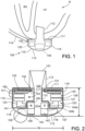
- an exemplary left ventricular assist blood pump 100 having a puck-shaped housing 110 is implanted in a patient's body with a first face 111 of the housing 110 positioned against the patient's heart H and a second face 113 of the housing 110 facing away from the heart H.
- the first face 111 of the housing 110 includes an inlet cannula 112 extending into the left ventricle LV of the heart H.
- the second face 113 of the housing 110 has a chamfered edge 114 to avoid irritating other tissue that may come into contact with the blood pump 100, such as the patient's diaphragm.
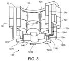
- the illustrated puck-shaped housing 110 includes a stator 120, also referred to herein as the magnetic core 120 or the core 120, and electronics 130, also referred to herein as control electronics 130 or controller 130, of the pump 100 positioned on the inflow side of the housing toward first face 111, and a rotor 140 of the pump 100 is positioned along the second face 113.
- the stator 120 can include pole pieces 123a-123f and windings 126 that can include, for example, a drive coil 125 and a levitation coil 127.
- the drive coil 125 can generate an electromagnetic field for creating a torque at the rotor 140 to cause the rotor 140 to rotate.
- the levitation coils 127 can generate an electromagnetic field to control the radial position of the rotor 140.
- one or both of the drive coil 125 and the levitation coil 127 can be sources of heat.
- the electronics 130 are positioned between the stator 120 and the first face 111 and the stator 120 is positioned between the electronics 130 and the second face 113.
- This positioning of the stator 120, electronics 130, and rotor 140 permits the edge 114 to be chamfered along the contour of the rotor 140, as illustrated in at least Figs. 2 , 4 , and 8-11 , for example.
- the puck-shaped housing 110 includes the stator 120 of the pump 100 positioned on the inflow side of the housing toward the first face 111, the electronics 130 of the pumps 100 positioned on the outflow side of the housing toward the second face 113.
- the blood pump 100 can generate heat during operation, which heat can increase, among other things, the surface temperatures of all or portions of the blood pump 100. In some embodiments, for example, this heat can be generated by losses and/or inefficiencies in the blood pump 100. In some embodiments, for example, the blood pump 100 can have an efficiency such as a hydraulic efficiency of: less than 0.8, less than 0.7, less than 0.6, less than 0.5, less than 0.4, less than 0.3, less than 0.2, between approximately 0.2 and 0.6, between approximately 0.3 and 0.5, of approximately 0.3, of approximately 0.38, of approximately 0.4, of approximately 0.42, of approximately 0.5, or any other or intermediate value.
- a hydraulic efficiency of: less than 0.8, less than 0.7, less than 0.6, less than 0.5, less than 0.4, less than 0.3, less than 0.2, between approximately 0.2 and 0.6, between approximately 0.3 and 0.5, of approximately 0.3, of approximately 0.38, of approximately 0.4, of approximately 0.42, of approximately 0.5, or any other or intermediate
- the blood pump can consume less than 50 W, less than 40 W, less than 30 W, less than 20 W, less than 10 W, less than 5 W, between approximately 1 W and 10 W, between approximately 2 W and 7 W, or any other or intermediate amount of power.
- the power consumption of the blood pump 100 varies based on the flow-rate and/or pressure of the blood exiting the blood pump 100.
- the blood pump 100 can consume approximately 1.9 W, which can include approximately 1 W of power consumed by the electronics 130, approximately 0.4 W of bearing losses, approximately 0.1 W of drive losses, and approximately 0.42 W for the driving of the rotor 140.
- the blood pump 100 can consume approximately 4.2 W, which can include approximately 1 W of power consumed by the electronics 130, approximately 0.5 W of bearing losses, approximately 0.65 W of drive losses, and approximately 2 W for the driving of the rotor 140.
- the blood pump 100 can consume approximately 6.6 W, which can include approximately 1 W of power consumed by the electronics 130, approximately 0.5 W of bearing losses, approximately 0.1.4 W of drive losses, and approximately 3.71 W for the driving of the rotor 140.
- the blood pump 100 and specifically the housing 110 includes a dividing wall 115, also referred to herein as the interior wall 115, within the housing 110 defining a blood flow conduit 103.
- the blood flow conduit 103 extends from an inlet opening 101 of the inlet cannula 112 through the stator 120 to an outlet opening 105 defined by the housing 110.
- the rotor 140 is positioned within the blood flow conduit 103.
- the stator 120 is disposed circumferentially about a first portion 140a of the rotor 140, for example about a permanent magnet 141.
- the stator 120 is also positioned relative to the rotor 140 such that, in use, blood flows within the blood flow conduit 103 through the stator 120 before reaching the rotor 140.
- the permanent magnet 141 has a permanent magnetic north pole N and a permanent magnetic south pole S for combined active and passive magnetic levitation of the rotor 140 and for rotation of the rotor 140.
- the rotor 140 also has a second portion 140b that includes impeller blades 143.
- the impeller blades 143 are located within a volute 107 of the blood flow conduit such that the impeller blades 143 are located proximate to the second face 113 of the housing.
- the puck-shaped housing 110 further includes a peripheral wall 116, also referred to herein as the exterior wall 116, that extends between the first face 111 and a removable cap 118.
- the peripheral wall 116 is formed as a hollow circular cylinder having a width W between opposing portions of the peripheral wall 116.
- the housing 110 also has a thickness T between the first face 111 and the second face 113 that is less than the width W.
- the thickness T is from about 0.5 inches to about 1.5 inches, and the width W is from about 1 inch to about 4 inches.
- the width W can be approximately 2 inches, and the thickness T can be approximately 1 inch.
- the peripheral wall 116 encloses an internal compartment 117 that surrounds the dividing wall 115 and the blood flow conduit 103.
- the internal compartment 117 can contain the stator 120, the electronics 130, or the stator 120 and the electronics 130.
- the stator 120 and/or the electronics 130 can be disposed in the internal compartment 117 about the dividing wall 115.
- the stator 120 and the electronics 130 can, in some embodiments, be positioned adjacent to each other. In such embodiments, the stator 120 and the electronics 130 are physically and electrically separated so that the stator 120 does not short the electronics 130. In some embodiments, this separation between the stator 120 and the electronics 130 can be achieved via an air-gap, or the placement of a potting material between the stator 120 and the electronics.
- the stator 120 and/or the electronics 130 located in the internal compartment 117 can be located in potting 150, and specifically can be located within a potting material that can fill some or all of any remaining portions of the internal compartment 117.
- This potting material can comprise a single potting material or multiple potting materials.
- the potting 150 can comprise any material fit for the environment and intended use, and can include, for example, a silicone or silicone compound, or an epoxy.
- the potting can be isotropic, and in other embodiments the potting 150 can be anisotropic.
- the potting 150 can comprise a first potting material have first properties covering a first portion of the stator 120 and/or the electronics 130 and the potting 150 can comprise a second potting material having second properties covering a second portion of the stator 120 and/or the electronics 130.
- the potting 150 can have isotropic thermal conductivity and/or can isotropically transfer heat from the electronics 130, and in some embodiments, the potting 150 can have anisotropic thermal conductivity and/or anisotropically transfer heat from the electronics 130.
- the potting material can have a thermal conductivity (k) of approximately: 0.1 W/(m*K); 0.26 W/(m*K); 0.5 W/(m*K); 0.75 W/(m*K); 1 W/(m*K); 2 W/(m*K); 3 W/(m*K); 5 W/(m*K); 10 W/(m*K); between 0.26 and 1 W/(m*K); or any other or intermediate value or range.
- k thermal conductivity
- the stator 120 and the electronics 130 can, in some embodiments, be connected by a thermal conductor 160, which thermal conductor 16 can contact one or both of the stator 120 and the electronics 130.
- the thermal conductor 160 can, in some embodiments, additionally connect the circuit boards 131 and/or the components 133 to facilitate heat transfer throughout the electronics 130 and to the stator 120.
- the thermal conductor 160 can comprise a thermal interface material that can create a path for thermal conduction from the electronics 130 to the stator 120 that extends through the potting 150 as, in some embodiments, the thermal conductor 160 can extend through the potting 150.
- the thermal interface material can include, for example, a thermal conductive pad, thermal grease, thermal glue, thermal gap filler, or thermal adhesive.
- the thermal conductor can comprise a thermal pad made of, for example, a silicone rubber having a thermal conductivity of, for example, approximately 17 W/(m*K).
- the thermal conductor 160 can be electrically non-conductive, but can have thermal conductivity (k) that is higher than typical non-conductors, and in some embodiments significantly higher than the thermal conductivity of some or all of the potting 150. Thus, in some embodiments, the thermal conductivity of the thermal conductor 160 can be relatively higher than the thermal conductivity of the potting 150.
- the thermal conductor 160 can have a thermal conductivity (k) or approximately: 5 W/(m ⁇ K); 10 W/(m ⁇ K); 15 W/(m ⁇ K); 17 W/(m ⁇ K); 20 W/(m ⁇ K); 25 W/(m ⁇ K); 30 W/(m ⁇ K); 50 W/(m ⁇ K); between 10 and 25 W/(m ⁇ K); or any other or intermediate value or range.
- one or both of: the back iron 121 and the pole pieces 123a-123f have thermal conductivity (k) that is higher, and in some embodiments significantly higher than the thermal conductivity of some or all of the potting 150.
- the thermal conductivity of the thermal conductor 160 and/or of one or both of the back iron 121 and the poles 123a-123f can be at least: 1.5 times; 2 times; 3 times; 4 times; 5 times; 6 times; 7 times; 8 times; 9 times; 10 times; 15 times; 20 times; 25 times; 50 times; 100 times; 500 times; 1000 times; or any other or intermediate multiple of the thermal conductivity of the potting 150. Due to this higher thermal conductivity of the thermal conductor 160, the thermal conductor preferentially thermally connects the electronics 130 and all or portions of the stator 120 such that heat flux through surfaces of the electronics 130 contacting the thermal conductor 160 is greater than heat flux through surfaces of the electronics 130 not contacting the thermal conductor 160.
- all or portions of the stator 120 can have isotropic thermal conductivity, and in some embodiments, the stator 120 can have anisotropic thermal conductivity.
- all or portions of the stator can comprise a laminated material, and specifically, all or portions of the poles 123a-123f can be laminated.
- the laminations 124d of the poles 123a-123f can have an anisotropic thermal conductivity.
- the thermal fast plane of the poles 123a-123f can be pointed inwards towards the blood conduit 103, and the thermally slow plane or axis can be pointed azimuthally or axially.
- the blood pump 100 can include multiple heat conduction pathways including a first conductive heat transfer pathway 162, also referred to herein as a first heat transfer pathway 162, and a second conductive heat transfer pathway 164, also referred to herein as a second heat transfer pathway 164.
- the first heat transfer pathway 162 is from the electronics 130 through the potting 150 surrounding the electronics 130. This first heat transfer pathway 162 extends in all directions from the electronics 130 in which the potting 150 contacts the electronics 130 and thermally connects the electronics 130 with the exterior wall 116 and/or the interior wall 115 of the blood pump 100.
- the second heat transfer pathway 164 partially extends in the direction of blood flow through the blood flow conduit 103, or in other words partially extends along the blood flow conduit 103.
- the second heat transfer pathway 164 is from the electronics 130 through the thermal conductor 160 and the stator 120, and terminates at a portion 166 of the interior wall 115 adjacent to an end 124c of the poles 123a-123f.
- This second heat transfer pathway 164 heats all or portions of the core 120 with heat from the electronics 130 or other components of the blood pump 100 thermally connected with the core 120.
- the second heat transfer pathway 164 is longer than the first heat transfer pathway 162.
- the portion 166 of the interior wall 115 circumferentially extends around the blood flow conduit 103 and defines a thermal zone 168 that is heated by the second heat transfer pathway 164.
- This thermal zone 168 is adjacent to the stator 120, and specifically is adjacent to the ends 124c of the poles 123a-123f.
- This thermal zone is preferentially heated by the second heat transfer pathway 164.
- the temperature of the thermal zone complies with regulatory requirements and does not create pain, discomfort, or injury in the patient.
- the blood in the blood flow conduit 103 is not heated to the point of causing pain, discomfort, or injury due to the flow of blood through the blood flow conduit 103.
- the thermal conductivity of components I the second heat transfer pathway 164 can be higher than the thermal conductivity of components in the first heat transfer pathways 162.
- the potting 150 can have a lower thermal conductivity than some or all of the components in the second heat transfer pathway 164.
- the potting 150 can insulate portions of the housing 110, and specifically of the external surface 116 of the housing 110 to minimize heat transfer to those insulated portions and to thereby facilitate heat transfer via the second heat transfer pathway 164.
- FIG. 5 illustrates another embodiment of a layout of the blood pump 100.
- the blood pump 100 the peripheral wall 116 encloses a first internal compartment 117a that surrounds the dividing wall 115 and the blood flow conduit 103.
- the first internal compartment 117a can contain the stator 120.
- the stator 120 can be disposed in the first internal compartment 117a about the dividing wall 115.
- the removable cap 118 defines a second internal compartment 117b that is located intermediated between the second face 113 and the volute 107 that is in fluid communication with the blood conduit 103 and the outlet opening 105.
- the second internal compartment 117b can contain the electronics 130 that can be potted within a second potting 151.
- the placement of the electronics 130 between the volute 107 and the second face 113 creates a heat transfer pathway 170 directly from the electronics 130 into the volute 107 at a thermal zone and to blood transiting through the volute 107.
- the thermal zone can, in some embodiments, be adjacent to the electronics 130.
- the electronics 130 can be embedded within the second potting 151 and positioned within the second internal compartment 117b such that the electronics are relatively more proximate to the volute 107 than to the second face 113 and/or so that the second potting is thicker between the electronics 130 and the second face 113 than between the electronics 130 and the volute 107. In some embodiments, this greater thickness of the potting between the electronics 130 and the second face 113 than between the electronics 130 and the volute 107 can result in more heat transfer from the electronics to the volute 107 and blood transiting through the volute than to the second face 113.
- the implanted blood pump 100 can include an electrical connector 172 located proximate to the second face 113 and/or the outlet opening 105.
- placement of the electronics 130 as depicted in FIG. 5 can facilitate location of an electrical connector 172 proximate to the second face 113 and/or the outlet opening 105, which placement of the electrical connector 172 can ease implantation of the blood pump 100.
- placement of the electrical connector 172 proximate to the outlet opening 105 of the blood pump can ease implantation by allowing similar placement of both the cable 119 connecting to the connector 172 and any conduit, tube, or channel connecting to the outlet opening 105 within the patient's body.
- the removable cap 118 includes the second face 113, the chamfered edge 114, and defines the outlet opening 105.
- the cap 118 can be threadably engaged with the peripheral wall 116 to seal the cap 118 in engagement with the peripheral wall 116.
- the cap 118 includes an inner surface 118a of the cap 118 that defines the volute 107 that is in fluid communication with the outlet opening 105.
- the electronics 130 are positioned adjacent to the first face 111 and the stator 120 is positioned adjacent to the electronics 130 on an opposite side of the electronics 130 from the first face 111.
- the electronics 130 include circuit boards 131 and various components 133 carried on the circuit boards 131 to control the operation of the pump 100 by controlling the electrical supply to the stator 120.
- the housing 110 is configured to receive the circuit boards 131 within the internal compartment 117 generally parallel to the first face 111 for efficient use of the space within the internal compartment 117.
- the circuit boards also extend radially-inward towards the dividing wall 115 and radially-outward towards the peripheral wall 116.
- the internal compartment 117 is generally sized no larger than necessary to accommodate the circuit boards 131, and space for heat dissipation, material expansion, potting materials, and/or other elements used in installing the circuit boards 131.
- the external shape of the housing 110 proximate the first face 111 generally fits the shape of the circuits boards 131 closely to provide external dimensions that are not much greater than the dimensions of the circuit boards 131.
- FIG. 6 illustrates another embodiment of a layout of the blood pump 100.
- the electronics 130 include first electronics 600 and second electronics 602.
- the first electronics 600 can include a first one or several: circuit boards such one or several printed circuit boards; one or several electrical components, or the like; and the second electronics 602 can include a second one or several: circuit boards such one or several printed circuit boards; one or several electrical components, or the like.
- the first electronics 600 can be located proximate to the first face 111 and the second electronics 602 can be located between the first electronics 600 and the second face 113.
- both the first electronics 600 and the second electronics 602 can be thermally coupled to the stator 120 via the thermal conductor 160, which thermal conductor 160 can be non-electrically conductive.
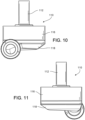
- FIG. 7 illustrates another embodiment of a layout of the blood pump 100.
- the blood flow conduit 103 does not extend from the first face 111 to the second face 113, but rather extends below the volute 107 towards the first face 111.
- the blood pump 100 includes the stator 120 and the windings 126. As further seen, the windings 126 and stator 120 are thermally connected to the electronics 130 via the thermal conductor 160.
- the blood pump 100 includes the inlet opening 101 located in the second face 113, which inlet opening 101 leads directly into the volute 107.
- This positioning of the inlet opening 101 in the second face 113 enables the placement of the electronics 130 in closer physical proximity to the blood flow conduit 103 and/or in closer thermal proximity to the blood flow conduit 103.
- blood is drawn into the blood flow conduit 103 and/or flows through the blood flow conduit 103 and heat is transferred to this blood flowing through the blood flow conduit 104 from the electronics 130 or other components of the blood pump 100, and in some embodiments, via the stator 120.
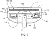
- the stator 120 includes a back iron 121 and pole pieces 123a-123f arranged at intervals around the dividing wall 115.
- the back iron 121 extends around the dividing wall 115 and is formed as a generally flat disc of a ferromagnetic material, such as steel, in order to conduct magnetic flux.
- the back iron 121 can, in some embodiments, be proximate to the control electronics 130. While the back iron 121 can be proximate to the control electronics 130, the back iron 121 is electrically unconnected to the electronics 130.
- the back iron 121 provides a base for the pole pieces 123a-123f.
- the thermal conductor 160 can connect to the stator 120 via the back iron 121 and/or via one or several of the pole pieces 123a-123f.
- Each of the pole piece 123a-123f is L-shaped and has a drive coil 125 for generating an electromagnetic field to rotate the rotor 140.
- the pole piece 123a has a first leg 124a that contacts the back iron 121 and extends from the back iron 121 towards the second face 113.
- the pole piece 123a also has a second leg 124b that extends from the first leg 124a towards the dividing wall 115 proximate the location of the permanent magnet 141 of the rotor 140.
- the second leg 124b terminates at the end 124c proximate to the interior wall 115.
- the end can be, for example, separated from the interior wall 115 by a distance or a gap of at least: 0.01 millimeters, 0.05 millimeters, 0.1 millimeters, 0.2 millimeters, 0.3 millimeters, 0.4 millimeters, 0.5 millimeters, 1 millimeter, 2 millimeters, 3 millimeters, 4 millimeters, 5 millimeters, between 0 millimeters and 5 millimeters, between 0.05 millimeters and 2.5 millimeters, between 0.05 millimeters and 2 millimeters, between 0.2 millimeters and 1.5 millimeters, between 0.5 millimeters and 1 millimeter, between 1 millimeter and 1.5 millimeters, between 1.5 millimeters and 2 millimeters, between 2 millimeters and 2.5 millimeters, or any other or intermediate distance.
- the second leg 124b, and specifically the end 124c is in thermal connection with a portion of the interior wall 115 proximate to the second leg 124 and can thereby transfer heat to blood transiting the blood flow conduit 103 during operation of the blood pump 100.
- Each of the pole pieces 123a-123f also has a levitation coil 127 for generating an electromagnetic field to control the radial position of the rotor 140.
- Each of the drive coils 125 and the levitation coils 127 includes multiple windings of a conductor around the pole pieces 123a-123f. Particularly, each of the drive coils 125 is wound around two adjacent ones of the pole pieces 123, such as pole pieces 123d and 123e, and each levitation coil 127 is wound around a single pole piece. The drive coils 125 and the levitation coils 127 are wound around the first legs of the pole pieces 123, and magnetic flux generated by passing electrical current though the coils 125 and 127 during use is conducted through the first legs and the second legs of the pole pieces 123 and the back iron 121.
- the drive coils 125 and the levitation coils 127 of the stator 120 are arranged in opposing pairs and are controlled to drive the rotor and to radially and axially levitate the rotor 140 by generating electromagnetic fields that interact with the permanent magnetic poles S and N of the permanent magnet 141. Because the stator 20 includes both the drive coils 125 and the levitation coils 127, only a single stator is needed to levitate the rotor 140 using only passive and active magnetic forces.
- the permanent magnet 141 in this configuration has only one magnetic moment and is formed from a monolithic permanent magnetic body 141.
- the stator 120 can be controlled as discussed in U.S. Patent No. 6,351,048 .
- the control electronics 130 and the stator 120 receive electrical power from a remote power supply via a cable 119 ( Fig. 1 ).
- the rotor 140 is arranged within the housing 110 such that its permanent magnet 141 is located upstream of impeller blades in a location closer to the inlet opening 101.
- the permanent magnet 141 is received within the blood flow conduit 103 proximate the second legs 124b of the pole pieces 123 to provide the passive axial centering force though interaction of the permanent magnet 141 and ferromagnetic material of the pole pieces 123.
- the permanent magnet 141 of the rotor 140 and the dividing wall 115 form a gap 108 between the permanent magnet 141 and the dividing wall 115 when the rotor 140 is centered within the dividing wall 115.
- the thermal zone 168 is located adjacent the gap 108 such that the gap is between the permanent magnet 141 and the portion 166 of the dividing wall 115.
- the gap 108 may be from about 0.2 millimeters to about 2 millimeters.
- the gap 108 is approximately 1 millimeter.
- the north permanent magnetic pole N and the south permanent magnetic pole S of the permanent magnet 141 provide a permanent magnetic attractive force between the rotor 140 and the stator 120 that acts as a passive axial centering force that tends to maintain the rotor 140 generally centered within the stator 120 and tends to resist the rotor 140 from moving towards the first face Ill or towards the second face 113.
- the rotor 140 also includes a shroud 145 that covers the ends of the impeller blades 143 facing the second face 113 that assists in directing blood flow into the volute 107.
- the shroud 145 and the inner surface 118a of the cap 118 form a gap 109 between the shroud 145 and the inner surface 118a when the rotor 140 is levitated by the stator 120.
- the gap 109 is from about 0.2 millimeters to about 2 millimeters. For example, the gap 109 is approximately 1 millimeter.
- the blood flow conduit 103 As blood flows through the blood flow conduit 103, blood flows through a central aperture 141 a formed through the permanent magnet 141. Blood also flows through the gap 108 between the rotor 140 and the dividing wall 115 and through the gap 109 between the shroud 145 and the inner surface 108a of the cap 118. During operation the gaps 108 and 109 are large enough to allow adequate blood flow to limit clot formation that may occur if the blood is allowed to become stagnant. The gaps 108 and 109 are also large enough to limit pressure forces on the blood cells such that the blood is not damaged when flowing through the pump 100.
- the rotor 140 is radially suspended by active control of the levitation coils 127 as discussed above, and because the rotor 140 is axially suspended by passive interaction of the permanent magnet 141 and the stator 120, no rotor levitation components are needed proximate the second face 113.
- the incorporation of all the components for rotor levitation in the stator 120 i.e., the levitation coils 127 and the pole pieces 123) allows the cap 118 to be contoured to the shape of the impeller blades 143 and the volute 107. Additionally, incorporation of the rotor levitation components in the stator 120 eliminates the need for electrical connectors extending from the compartment 117 to the cap 118, which allows the cap to be easily installed and/or removed and eliminates potential sources of pump failure.
- the drive coils 125 of the stator 120 generates electromagnetic fields through the pole pieces 123 that selectively attract and repel the magnetic north pole N and the magnetic south pole S of the rotor 140 to cause the rotor 140 to rotate within stator 120.
- the impeller blades 143 force blood into the volute 107 such that blood is forced out of the outlet opening 105.
- the rotor draws blood into pump 100 through the inlet opening 101.
- the blood flows through the inlet opening 101 and flows through the control electronics 130 and the stator 120 toward the rotor 140.
- the blood passes through the control electronics 130 and the stator 120, the blood passes through the thermal zone 168 defined by the portion 166 of the interior wall 115 that is heated by the second conductive heat transfer pathway 164. Heat transfers from the electronics 130 into the blood in the thermal zone 168. Blood flows through the aperture 141a of the permanent magnet 141 and between the impeller blades 143, the shroud 145, and the permanent magnet 141, and into the volute 107. Blood also flows around the rotor 140, through the gap 108 and through the gap 109 between the shroud 145 and the inner surface 118a of the cap 118. The blood exits the volute 107 through the outlet opening 105.
- the drive coils 125 of the stator 120 generates electromagnetic fields through the pole pieces 123 that selectively attract and repel the magnetic north pole N and the magnetic south pole S of the rotor 140 to cause the rotor 140 to rotate within stator 120.
- the impeller blades 143 force blood into the volute 107 such that blood is forced out of the outlet opening 105.
- the rotor draws blood into pump 100 through the inlet opening 101.
- the blood flows through the inlet opening 101 and flows through the stator 120 toward the rotor 140.
- the cap 118 can be engaged with the peripheral wall 116 using a different attachment mechanism or technique, such as snap-fit engagement, adhesives, and/or welding.
- the cap 118 has been described as defining the outlet opening 105 and the chamfered edge 114, the outlet opening 105 and/or the chamfered edge 114 can be defined by the peripheral wall 116 or by both the peripheral wall 116 and the cap 118.
- the dividing wall 115 can be formed as part of the cap 118.
- the rotor 140 can include two or more permanent magnets.
- the number and configuration of the pole pieces 123 can also be varied.
- the operation of the control electronics 130 is selected to account for the number and position of pole pieces of the stator and permanent magnets of the rotor.
- the cap 118 can be engaged with the peripheral wall using other techniques, such as adhesives, welding, snap-fit, shrink-fit, or other technique or structure.
- the first face 111 may be formed from a separate piece of material than the peripheral wall 116 and the first face 111, including the inlet cannula 112, can be attached to the peripheral wall 116, such as by welding, after the control electronics 130 and the stator 120 have been mounted in the internal compartment 117.
- the shroud 145 may be omitted and optionally replaced by other flow control devices to achieve a desired pump efficiency.
- the control electronics 130 can be located external to the pump 100, such as in a separate housing implanted in the patient's abdomen, or external to the patient's body.
- the dimensions of the housing 110 can be larger or smaller than those described above.
- the ratio of the width W of the housing 110 to the thickness T of the housing can be different than the ratio described above.
- the width W can be from about 1.1 to about 5 times greater than the thickness T.
- the permanent magnet 141 of the rotor 140 can include two or more pairs of north and south magnetic poles. While the peripheral wall 116 and the dividing wall 115 are illustrated as cylinders having circular cross-sectional shapes, one or both can alternatively be formed having other cross-sectional shapes, such as oval, or an irregular shape. Similarly, the peripheral wall 116 can be tapered such that the housing does not have a constant width W from the first face Ill to the second face 113.
- the blood pump 100 can be used to assist a patient's heart during a transition period, such as during a recovery from illness and/or surgery or other treatment.
- the blood pump 100 can be used to partially or completely replace the function of the patient's heart on a generally permanent basis, such as where the patient's aortic valve is surgically sealed.
- FIG. 16 illustrates another embodiment of a layout of the blood pump 100.
- the layout of the blood pump 100 in FIG. 16 is similar to the layout of the blood pump 100 in FIG. 7 , with the exception that the blood pump 100 in FIG. 16 includes the pole pieces 123a-123f and windings 126 similar to those shown in FIG. 2 . and windings 126 that can include, for example, a drive coil 125 and a levitation coil 127.
- FIG. 17 illustrates another embodiment of a layout of the blood pump 100.
- the layout of the blood pump 100 in FIG. 17 is similar to the layout of the blood pump 100 in FIG. 2 , with the exception that the blood pump 100 in FIG. 17 does not include L-shaped pole pieces 123a-123f, but rather includes the stator 120 and the windings 126 configured so the windings 126 are positioned adjacent to the permanent magnet 141 attached to the rotor 140.
Landscapes
- Health & Medical Sciences (AREA)
- Heart & Thoracic Surgery (AREA)
- Engineering & Computer Science (AREA)
- Cardiology (AREA)
- Biomedical Technology (AREA)
- Anesthesiology (AREA)
- Mechanical Engineering (AREA)
- Hematology (AREA)
- Life Sciences & Earth Sciences (AREA)
- Animal Behavior & Ethology (AREA)
- General Health & Medical Sciences (AREA)
- Public Health (AREA)
- Veterinary Medicine (AREA)
- Vascular Medicine (AREA)
- External Artificial Organs (AREA)
Claims (15)
- Pompe à sang implantable (100), comprenant:un corps de pompe (110) comprenant une paroi (115) définissant une conduite d'écoulement de sang (103) s'étendant à travers le corps de pompe (110) et un volume interne;un rotor (140) comprenant un aimant (141) et disposé à l'intérieur de la conduite d'écoulement de sang (103);un noyau magnétique (120) disposé dans le volume interne et s'étendant de manière circonférentielle autour de la conduite d'écoulement de sang (103) et du rotor (140),dans laquelle le noyau magnétique (120) se termine à proximité de la paroi (115); etun dispositif de commande (130) disposé dans le volume interne;une voie de transfert thermique continu s'étendant à travers le noyau magnétique (120) entre le dispositif de commande (130) et la paroi (115) pour transférer de la chaleur au sang transitant dans la conduite d'écoulement de sang (103); et caractérisé en ce queun conducteur thermique (160) couple thermiquement le dispositif de commande (130) au noyau magnétique (120) de sorte à fournir un passage souhaité de moindre résistance pour un écoulement de chaleur généré par la pompe à sang (100) vers le sang transitant dans la conduite d'écoulement de sang (103), dans laquelle le conducteur thermique (160) comprend un matériau d'interface thermique, et dans laquelle le conducteur thermique (160) a une conductivité thermique (k) d'au moins 5 W/(m∗K).
- Pompe à sang implantable selon la revendication 1, dans laquelle le matériau d'interface thermique comprend un tampon de conduction thermique ou une graisse thermique.
- Pompe à sang implantable selon la revendication 1 ou selon l'une quelconque des revendications précédentes, comprenant en outre un matériau d'enrobage entourant le noyau magnétique (120) et le dispositif de commande (130).
- Pompe à sang implantable selon la revendication 3, dans laquelle le matériau d'enrobage est configuré pour transférer de manière isotrope de la chaleur provenant du dispositif de commande (130).
- Pompe à sang implantable selon la revendication 3, dans laquelle le conducteur thermique (160) a une conductivité thermique supérieure à celle du matériau d'enrobage.
- Pompe à sang implantable selon l'une quelconque des revendications 3 à 5, dans laquelle le matériau d'enrobage comprend un époxyde.
- Pompe à sang implantable selon la revendication 6, dans laquelle l'époxyde a une conductivité thermique isotrope.
- Pompe à sang implantable selon la revendication 1 ou selon l'une quelconque des revendications précédentes, dans laquelle la conduite d'écoulement de sang (103) comprend une entrée (101) et une sortie (105), et dans laquelle le dispositif de commande (130) est positionné relativement plus près de l'entrée (101) de la conduite d'écoulement de sang (103) que le noyau magnétique (120).
- Pompe à sang implantable selon la revendication 8 ou selon l'une quelconque des revendications précédentes, dans laquelle le noyau magnétique (120) comprend une pluralité de pièces polaires en forme de L (123a à 123f).
- Pompe à sang implantable selon la revendication 1 ou selon l'une quelconque des revendications précédentes, dans laquelle le conducteur thermique (160) est non conducteur électrique.
- Pompe à sang implantable selon la revendication 1 ou selon l'une quelconque des revendications précédentes, dans laquelle le noyau magnétique (120) comprend une pluralité de pièces polaires (123a à 123f) agencées de manière circonférentielle autour de la conduite d'écoulement de sang (103).
- Pompe à sang implantable selon la revendication 11, dans laquelle chacune des pièces polaires (123a à 123f) comprend une première patte (124a) s'étendant le long de la conduite d'écoulement de sang (103) et une deuxième patte (124b) qui s'étend vers la paroi (115).
- Pompe à sang implantable selon la revendication 12, dans laquelle une extrémité (124c) de chacune des deuxièmes pattes (124b) est séparée de la paroi (115) par un espace allant de 0,05 mm à 2 mm.
- Pompe à sang implantable selon la revendication 11, dans laquelle le conducteur thermique (160) entre en contact avec le noyau magnétique (120) par l'intermédiaire d'au moins une des pièces polaires (123a à 123f).
- Pompe à sang implantable selon la revendication 11, dans laquelle le noyau magnétique (120) comprend un contre-fer (121), et dans laquelle le conducteur thermique (160) entre en contact avec le noyau magnétique (120) par l'intermédiaire du contre-fer (121).
Priority Applications (1)
| Application Number | Priority Date | Filing Date | Title |
|---|---|---|---|
| EP23201229.4A EP4295895A3 (fr) | 2017-05-11 | 2018-05-10 | Interconnexion thermique pour pompe à sang implantable |
Applications Claiming Priority (2)
| Application Number | Priority Date | Filing Date | Title |
|---|---|---|---|
| US201762505020P | 2017-05-11 | 2017-05-11 | |
| PCT/US2018/032137 WO2018209130A1 (fr) | 2017-05-11 | 2018-05-10 | Interconnexion thermique pour pompe à sang implantable |
Related Child Applications (1)
| Application Number | Title | Priority Date | Filing Date |
|---|---|---|---|
| EP23201229.4A Division EP4295895A3 (fr) | 2017-05-11 | 2018-05-10 | Interconnexion thermique pour pompe à sang implantable |
Publications (2)
| Publication Number | Publication Date |
|---|---|
| EP3621669A1 EP3621669A1 (fr) | 2020-03-18 |
| EP3621669B1 true EP3621669B1 (fr) | 2023-11-01 |
Family
ID=62245542
Family Applications (2)
| Application Number | Title | Priority Date | Filing Date |
|---|---|---|---|
| EP23201229.4A Pending EP4295895A3 (fr) | 2017-05-11 | 2018-05-10 | Interconnexion thermique pour pompe à sang implantable |
| EP18727621.7A Active EP3621669B1 (fr) | 2017-05-11 | 2018-05-10 | Interconnexion thermique pour pompe à sang implantable |
Family Applications Before (1)
| Application Number | Title | Priority Date | Filing Date |
|---|---|---|---|
| EP23201229.4A Pending EP4295895A3 (fr) | 2017-05-11 | 2018-05-10 | Interconnexion thermique pour pompe à sang implantable |
Country Status (3)
| Country | Link |
|---|---|
| US (3) | US11013905B2 (fr) |
| EP (2) | EP4295895A3 (fr) |
| WO (1) | WO2018209130A1 (fr) |
Families Citing this family (22)
| Publication number | Priority date | Publication date | Assignee | Title |
|---|---|---|---|---|
| EP4295895A3 (fr) | 2017-05-11 | 2024-03-27 | Tc1 Llc | Interconnexion thermique pour pompe à sang implantable |
| DE102018207575A1 (de) | 2018-05-16 | 2019-11-21 | Kardion Gmbh | Magnetische Stirndreh-Kupplung zur Übertragung von Drehmomenten |
| DE102018207594A1 (de) | 2018-05-16 | 2019-11-21 | Kardion Gmbh | Rotor, Magnetkupplungsvorrichtung, Elektromotor für ein Herzunterstützungssystem, Pumpeneinheit für ein Herzunterstützungssystem sowie Verfahren zum Herstellen eines Rotors |
| DE102018208550A1 (de) | 2018-05-30 | 2019-12-05 | Kardion Gmbh | Leitungsvorrichtung zum Leiten eines Blutstroms für ein Herzunterstützungssystem, Herzunterstützungssystem und Verfahren zum Herstellen einer Leitungsvorrichtung |
| DE102018208538A1 (de) | 2018-05-30 | 2019-12-05 | Kardion Gmbh | Intravasale Blutpumpe und Verfahren zur Herstellung von elektrischen Leiterbahnen |
| DE102018208541A1 (de) | 2018-05-30 | 2019-12-05 | Kardion Gmbh | Axialpumpe für ein Herzunterstützungssystem und Verfahren zum Herstellen einer Axialpumpe für ein Herzunterstützungssystem |
| DE102018208549A1 (de) | 2018-05-30 | 2019-12-05 | Kardion Gmbh | Elektronikmodul für ein Herzunterstützungssystem und Verfahren zum Herstellen eines Elektronikmoduls für ein Herzunterstützungssystem |
| DE102018208539A1 (de) | 2018-05-30 | 2019-12-05 | Kardion Gmbh | Motorgehäusemodul zum Abdichten eines Motorraums eines Motors eines Herzunterstützungssystems und Herzunterstützungssystem und Verfahren zum Montieren eines Herzunterstützungssystems |
| DE102018210058A1 (de) | 2018-06-21 | 2019-12-24 | Kardion Gmbh | Statorschaufelvorrichtung zur Strömungsführung eines aus einer Austrittsöffnung eines Herzunterstützungssystems ausströmenden Fluids, Herzunterstützungssystem mit Statorschaufelvorrichtung, Verfahren zum Betreiben einer Statorschaufelvorrichtung und Herstellverfahren |
| DE102018210076A1 (de) | 2018-06-21 | 2019-12-24 | Kardion Gmbh | Verfahren und Vorrichtung zum Erkennen eines Verschleißzustands eines Herzunterstützungssystems, Verfahren und Vorrichtung zum Betreiben eines Herzunterstützungssystems und Herzunterstützungssystem |
| DE102018211297A1 (de) | 2018-07-09 | 2020-01-09 | Kardion Gmbh | Herzunterstützungssystem und Verfahren zur Überwachung der Integrität einer Haltestruktur eines Herzunterstützungssystems |
| DE102018211328A1 (de) | 2018-07-10 | 2020-01-16 | Kardion Gmbh | Laufradgehäuse für ein implantierbares, vaskuläres Unterstützungssystem |
| DE102018211327A1 (de) | 2018-07-10 | 2020-01-16 | Kardion Gmbh | Laufrad für ein implantierbares, vaskuläres Unterstützungssystem |
| AU2019320533B2 (en) | 2018-08-07 | 2024-11-21 | Kardion Gmbh | Bearing device for a cardiac support system, and method for flushing an intermediate space in a bearing device for a cardiac support system |
| EP3701979A1 (fr) * | 2019-02-26 | 2020-09-02 | Berlin Heart GmbH | Pompe à sang pouvant être implantée permettant de supporter une fonction cardiaque |
| DE102020102474A1 (de) | 2020-01-31 | 2021-08-05 | Kardion Gmbh | Pumpe zum Fördern eines Fluids und Verfahren zum Herstellen einer Pumpe |
| CA3192451A1 (fr) | 2020-09-14 | 2022-03-17 | Johannes Bette | Pompe de support cardiovasculaire dotee d'un impulseur a zone d'ecoulement variable |
| CN112370655B (zh) * | 2020-11-13 | 2024-12-27 | 深圳核心医疗科技股份有限公司 | 血泵 |
| JP2023550938A (ja) | 2020-11-20 | 2023-12-06 | カルディオン ゲーエムベーハー | ガイドワイヤ補助具付き機械的循環支持システム |
| JP2022168836A (ja) * | 2021-04-26 | 2022-11-08 | レヴィトロニクス ゲーエムベーハー | 電磁回転駆動装置、遠心ポンプ、及びポンプ・ユニット |
| TW202335698A (zh) * | 2022-01-28 | 2023-09-16 | 德商阿比奥梅德歐洲有限公司 | 血液泵 |
| CN120381611A (zh) * | 2024-01-26 | 2025-07-29 | 心擎医疗(苏州)股份有限公司 | 用于体外式血泵的马达以及体外式血泵 |
Family Cites Families (52)
| Publication number | Priority date | Publication date | Assignee | Title |
|---|---|---|---|---|
| US4394448A (en) | 1978-02-24 | 1983-07-19 | Szoka Jr Francis C | Method of inserting DNA into living cells |
| DE3068743D1 (en) | 1980-01-16 | 1984-08-30 | Weder Hans G | Process and dialysis-installation for the preparation of bilayer-vesicles and their use |
| US4598051A (en) | 1980-03-12 | 1986-07-01 | The Regents Of The University Of California | Liposome conjugates and diagnostic methods therewith |
| US4515736A (en) | 1983-05-12 | 1985-05-07 | The Regents Of The University Of California | Method for encapsulating materials into liposomes |
| US4897355A (en) | 1985-01-07 | 1990-01-30 | Syntex (U.S.A.) Inc. | N[ω,(ω-1)-dialkyloxy]- and N-[ω,(ω-1)-dialkenyloxy]-alk-1-yl-N,N,N-tetrasubstituted ammonium lipids and uses therefor |
| US5208036A (en) | 1985-01-07 | 1993-05-04 | Syntex (U.S.A.) Inc. | N-(ω, (ω-1)-dialkyloxy)- and N-(ω, (ω-1)-dialkenyloxy)-alk-1-yl-N,N,N-tetrasubstituted ammonium lipids and uses therefor |
| US5550289A (en) | 1985-01-07 | 1996-08-27 | Syntex (U.S.A.) Inc. | N-(1,(1-1)-dialkyloxy)-and N-(1,(1-1)-dialkenyloxy alk-1-yl-N-N,N-tetrasubstituted ammonium lipids and uses therefor |
| US5320906A (en) | 1986-12-15 | 1994-06-14 | Vestar, Inc. | Delivery vehicles with amphiphile-associated active ingredient |
| US5703055A (en) | 1989-03-21 | 1997-12-30 | Wisconsin Alumni Research Foundation | Generation of antibodies through lipid mediated DNA delivery |
| FR2645866B1 (fr) | 1989-04-17 | 1991-07-05 | Centre Nat Rech Scient | Nouvelles lipopolyamines, leur preparation et leur emploi |
| US5013556A (en) | 1989-10-20 | 1991-05-07 | Liposome Technology, Inc. | Liposomes with enhanced circulation time |
| US5225212A (en) | 1989-10-20 | 1993-07-06 | Liposome Technology, Inc. | Microreservoir liposome composition and method |
| US5279833A (en) | 1990-04-04 | 1994-01-18 | Yale University | Liposomal transfection of nucleic acids into animal cells |
| US5264618A (en) | 1990-04-19 | 1993-11-23 | Vical, Inc. | Cationic lipids for intracellular delivery of biologically active molecules |
| US5283185A (en) | 1991-08-28 | 1994-02-01 | University Of Tennessee Research Corporation | Method for delivering nucleic acids into cells |
| US5858784A (en) | 1991-12-17 | 1999-01-12 | The Regents Of The University Of California | Expression of cloned genes in the lung by aerosol- and liposome-based delivery |
| WO1993017125A1 (fr) | 1992-02-19 | 1993-09-02 | Baylor College Of Medicine | Modulation de la croissance cellulaire au moyen d'oligonucleotides |
| US5334761A (en) | 1992-08-28 | 1994-08-02 | Life Technologies, Inc. | Cationic lipids |
| US5578475A (en) | 1993-07-12 | 1996-11-26 | Life Technologies, Inc. | Composition and methods for transfecting eukaryotic cells |
| US5674908A (en) | 1993-12-20 | 1997-10-07 | Life Technologies, Inc. | Highly packed polycationic ammonium, sulfonium and phosphonium lipids |
| US6075012A (en) | 1994-02-11 | 2000-06-13 | Life Technologies, Inc. | Reagents for intracellular delivery of macromolecules |
| US5820873A (en) | 1994-09-30 | 1998-10-13 | The University Of British Columbia | Polyethylene glycol modified ceramide lipids and liposome uses thereof |
| US5753613A (en) | 1994-09-30 | 1998-05-19 | Inex Pharmaceuticals Corporation | Compositions for the introduction of polyanionic materials into cells |
| US5885613A (en) | 1994-09-30 | 1999-03-23 | The University Of British Columbia | Bilayer stabilizing components and their use in forming programmable fusogenic liposomes |
| US5627159A (en) | 1994-10-27 | 1997-05-06 | Life Technologies, Inc. | Enhancement of lipid cationic transfections in the presence of serum |
| EP0874910A4 (fr) | 1995-06-07 | 1999-04-21 | Life Technologies Inc | Transfection par lipides cationiques amelioree par des peptides |
| EP0840744A4 (fr) | 1995-06-07 | 1999-03-10 | Genta Inc | Nouveaux lipides cationiques a base d'acide phosphonique |
| US5705385A (en) | 1995-06-07 | 1998-01-06 | Inex Pharmaceuticals Corporation | Lipid-nucleic acid particles prepared via a hydrophobic lipid-nucleic acid complex intermediate and use for gene transfer |
| US5976567A (en) | 1995-06-07 | 1999-11-02 | Inex Pharmaceuticals Corp. | Lipid-nucleic acid particles prepared via a hydrophobic lipid-nucleic acid complex intermediate and use for gene transfer |
| US5981501A (en) | 1995-06-07 | 1999-11-09 | Inex Pharmaceuticals Corp. | Methods for encapsulating plasmids in lipid bilayers |
| US6051429A (en) | 1995-06-07 | 2000-04-18 | Life Technologies, Inc. | Peptide-enhanced cationic lipid transfections |
| WO1996040726A1 (fr) | 1995-06-07 | 1996-12-19 | Genta Incorporated | Nouveaux lipides cationiques a base de carbamate |
| US6339173B1 (en) | 1996-07-22 | 2002-01-15 | Promega Biosciences, Inc. | Amide-based cationic lipids |
| US6020526A (en) | 1995-07-21 | 2000-02-01 | Genta, Incorporated | Amide-based cationic lipids |
| US5817856A (en) | 1995-12-11 | 1998-10-06 | Yissum Research Development Company Of The Hebrew University Of Jerusalem | Radiation-protective phospholipid and method |
| US6284267B1 (en) | 1996-08-14 | 2001-09-04 | Nutrimed Biotech | Amphiphilic materials and liposome formulations thereof |
| US6034135A (en) | 1997-03-06 | 2000-03-07 | Promega Biosciences, Inc. | Dimeric cationic lipids |
| US5877220A (en) | 1997-03-06 | 1999-03-02 | Genta, Incorporated | Amide-based oligomeric cationic lipids |
| US6093001A (en) * | 1997-05-02 | 2000-07-25 | University Of Pittsburgh | Rotary pump having a bearing which dissipates heat |
| AU733310C (en) | 1997-05-14 | 2001-11-29 | University Of British Columbia, The | High efficiency encapsulation of charged therapeutic agents in lipid vesicles |
| AU3105899A (en) * | 1998-03-30 | 1999-10-18 | Nimbus, Inc. | Sealed motor stator assembly for implantable blood pump |
| EP1063753B1 (fr) | 1999-06-22 | 2009-07-22 | Levitronix LLC | Entraînement électrique rotatif comprenant un rotor suspendu magnétiquement |
| US6547530B2 (en) * | 2000-05-19 | 2003-04-15 | Ntn Corporation | Fluid pump apparatus |
| US20040210289A1 (en) * | 2002-03-04 | 2004-10-21 | Xingwu Wang | Novel nanomagnetic particles |
| US6716157B2 (en) | 2002-02-28 | 2004-04-06 | Michael P. Goldowsky | Magnetic suspension blood pump |
| US20060287697A1 (en) * | 2003-05-28 | 2006-12-21 | Medcool, Inc. | Methods and apparatus for thermally activating a console of a thermal delivery system |
| JP5571087B2 (ja) * | 2008-09-26 | 2014-08-13 | ワールドハート インコーポレーテッド | 磁気浮上血液ポンプ及び該ポンプの小型化を可能にする最適化方法 |
| EP3248628B1 (fr) * | 2010-08-20 | 2019-01-02 | Tc1 Llc | Pompe sanguine implantable |
| US9192705B2 (en) * | 2013-03-25 | 2015-11-24 | Thoratec Corporation | Percutaneous cable with redundant conductors for implantable blood pump |
| DE102013013700A1 (de) * | 2013-04-05 | 2014-10-09 | CircuLite GmbH | Implantierbare Blutpumpe, Blutpumpensystem und Verfahren zur Datenübertragung in einem Blutpumpensystem |
| WO2016086137A1 (fr) * | 2014-11-26 | 2016-06-02 | Thoratec Corporation | Pompe et procédé de pompage de sang hélicocentrifuge |
| EP4295895A3 (fr) | 2017-05-11 | 2024-03-27 | Tc1 Llc | Interconnexion thermique pour pompe à sang implantable |
-
2018
- 2018-05-10 EP EP23201229.4A patent/EP4295895A3/fr active Pending
- 2018-05-10 US US15/976,719 patent/US11013905B2/en active Active
- 2018-05-10 WO PCT/US2018/032137 patent/WO2018209130A1/fr not_active Ceased
- 2018-05-10 EP EP18727621.7A patent/EP3621669B1/fr active Active
-
2021
- 2021-04-22 US US17/237,339 patent/US12017054B2/en active Active
-
2024
- 2024-05-24 US US18/673,788 patent/US20240350791A1/en active Pending
Also Published As
| Publication number | Publication date |
|---|---|
| US11013905B2 (en) | 2021-05-25 |
| EP3621669A1 (fr) | 2020-03-18 |
| US20210236800A1 (en) | 2021-08-05 |
| EP4295895A3 (fr) | 2024-03-27 |
| WO2018209130A1 (fr) | 2018-11-15 |
| US20180326133A1 (en) | 2018-11-15 |
| US12017054B2 (en) | 2024-06-25 |
| EP4295895A2 (fr) | 2023-12-27 |
| US20240350791A1 (en) | 2024-10-24 |
Similar Documents
| Publication | Publication Date | Title |
|---|---|---|
| US12017054B2 (en) | Thermal interconnect for implantable blood pump | |
| US9091271B2 (en) | Implantable blood pump | |
| US12383725B2 (en) | Bearingless implantable blood pump | |
| US12521542B2 (en) | Circulatory support system | |
| US10702641B2 (en) | Ventricular assist devices having a hollow rotor and methods of use | |
| US10722632B2 (en) | Blood pump controllers and methods of use for improved energy efficiency | |
| US10413650B2 (en) | Hall sensor mounting in an implantable blood pump |
Legal Events
| Date | Code | Title | Description |
|---|---|---|---|
| STAA | Information on the status of an ep patent application or granted ep patent |
Free format text: STATUS: UNKNOWN |
|
| STAA | Information on the status of an ep patent application or granted ep patent |
Free format text: STATUS: THE INTERNATIONAL PUBLICATION HAS BEEN MADE |
|
| PUAI | Public reference made under article 153(3) epc to a published international application that has entered the european phase |
Free format text: ORIGINAL CODE: 0009012 |
|
| STAA | Information on the status of an ep patent application or granted ep patent |
Free format text: STATUS: REQUEST FOR EXAMINATION WAS MADE |
|
| 17P | Request for examination filed |
Effective date: 20191115 |
|
| AK | Designated contracting states |
Kind code of ref document: A1 Designated state(s): AL AT BE BG CH CY CZ DE DK EE ES FI FR GB GR HR HU IE IS IT LI LT LU LV MC MK MT NL NO PL PT RO RS SE SI SK SM TR |
|
| AX | Request for extension of the european patent |
Extension state: BA ME |
|
| DAV | Request for validation of the european patent (deleted) | ||
| DAX | Request for extension of the european patent (deleted) | ||
| STAA | Information on the status of an ep patent application or granted ep patent |
Free format text: STATUS: EXAMINATION IS IN PROGRESS |
|
| 17Q | First examination report despatched |
Effective date: 20211220 |
|
| REG | Reference to a national code |
Ref country code: DE Free format text: PREVIOUS MAIN CLASS: A61M0001100000 Ref country code: DE Ref legal event code: R079 Ref document number: 602018060353 Country of ref document: DE Free format text: PREVIOUS MAIN CLASS: A61M0001100000 Ipc: A61M0060178000 |
|
| GRAP | Despatch of communication of intention to grant a patent |
Free format text: ORIGINAL CODE: EPIDOSNIGR1 |
|
| STAA | Information on the status of an ep patent application or granted ep patent |
Free format text: STATUS: GRANT OF PATENT IS INTENDED |
|
| RIC1 | Information provided on ipc code assigned before grant |
Ipc: A61M 60/81 20210101ALI20230421BHEP Ipc: A61M 60/508 20210101ALI20230421BHEP Ipc: A61M 60/422 20210101ALI20230421BHEP Ipc: A61M 60/216 20210101ALI20230421BHEP Ipc: A61M 60/178 20210101AFI20230421BHEP |
|
| INTG | Intention to grant announced |
Effective date: 20230524 |
|
| P01 | Opt-out of the competence of the unified patent court (upc) registered |
Effective date: 20230616 |
|
| GRAS | Grant fee paid |
Free format text: ORIGINAL CODE: EPIDOSNIGR3 |
|
| GRAA | (expected) grant |
Free format text: ORIGINAL CODE: 0009210 |
|
| STAA | Information on the status of an ep patent application or granted ep patent |
Free format text: STATUS: THE PATENT HAS BEEN GRANTED |
|
| AK | Designated contracting states |
Kind code of ref document: B1 Designated state(s): AL AT BE BG CH CY CZ DE DK EE ES FI FR GB GR HR HU IE IS IT LI LT LU LV MC MK MT NL NO PL PT RO RS SE SI SK SM TR |
|
| REG | Reference to a national code |
Ref country code: GB Ref legal event code: FG4D |
|
| REG | Reference to a national code |
Ref country code: CH Ref legal event code: EP |
|
| REG | Reference to a national code |
Ref country code: IE Ref legal event code: FG4D |
|
| REG | Reference to a national code |
Ref country code: DE Ref legal event code: R096 Ref document number: 602018060353 Country of ref document: DE |
|
| REG | Reference to a national code |
Ref country code: LT Ref legal event code: MG9D |
|
| REG | Reference to a national code |
Ref country code: NL Ref legal event code: MP Effective date: 20231101 |
|
| PG25 | Lapsed in a contracting state [announced via postgrant information from national office to epo] |
Ref country code: GR Free format text: LAPSE BECAUSE OF FAILURE TO SUBMIT A TRANSLATION OF THE DESCRIPTION OR TO PAY THE FEE WITHIN THE PRESCRIBED TIME-LIMIT Effective date: 20240202 |
|
| PG25 | Lapsed in a contracting state [announced via postgrant information from national office to epo] |
Ref country code: IS Free format text: LAPSE BECAUSE OF FAILURE TO SUBMIT A TRANSLATION OF THE DESCRIPTION OR TO PAY THE FEE WITHIN THE PRESCRIBED TIME-LIMIT Effective date: 20240301 |
|
| PG25 | Lapsed in a contracting state [announced via postgrant information from national office to epo] |
Ref country code: LT Free format text: LAPSE BECAUSE OF FAILURE TO SUBMIT A TRANSLATION OF THE DESCRIPTION OR TO PAY THE FEE WITHIN THE PRESCRIBED TIME-LIMIT Effective date: 20231101 |
|
| REG | Reference to a national code |
Ref country code: AT Ref legal event code: MK05 Ref document number: 1626523 Country of ref document: AT Kind code of ref document: T Effective date: 20231101 |
|
| PG25 | Lapsed in a contracting state [announced via postgrant information from national office to epo] |
Ref country code: NL Free format text: LAPSE BECAUSE OF FAILURE TO SUBMIT A TRANSLATION OF THE DESCRIPTION OR TO PAY THE FEE WITHIN THE PRESCRIBED TIME-LIMIT Effective date: 20231101 |
|
| PG25 | Lapsed in a contracting state [announced via postgrant information from national office to epo] |
Ref country code: AT Free format text: LAPSE BECAUSE OF FAILURE TO SUBMIT A TRANSLATION OF THE DESCRIPTION OR TO PAY THE FEE WITHIN THE PRESCRIBED TIME-LIMIT Effective date: 20231101 |
|
| PG25 | Lapsed in a contracting state [announced via postgrant information from national office to epo] |
Ref country code: ES Free format text: LAPSE BECAUSE OF FAILURE TO SUBMIT A TRANSLATION OF THE DESCRIPTION OR TO PAY THE FEE WITHIN THE PRESCRIBED TIME-LIMIT Effective date: 20231101 |
|
| PG25 | Lapsed in a contracting state [announced via postgrant information from national office to epo] |
Ref country code: NL Free format text: LAPSE BECAUSE OF FAILURE TO SUBMIT A TRANSLATION OF THE DESCRIPTION OR TO PAY THE FEE WITHIN THE PRESCRIBED TIME-LIMIT Effective date: 20231101 Ref country code: LT Free format text: LAPSE BECAUSE OF FAILURE TO SUBMIT A TRANSLATION OF THE DESCRIPTION OR TO PAY THE FEE WITHIN THE PRESCRIBED TIME-LIMIT Effective date: 20231101 Ref country code: IS Free format text: LAPSE BECAUSE OF FAILURE TO SUBMIT A TRANSLATION OF THE DESCRIPTION OR TO PAY THE FEE WITHIN THE PRESCRIBED TIME-LIMIT Effective date: 20240301 Ref country code: GR Free format text: LAPSE BECAUSE OF FAILURE TO SUBMIT A TRANSLATION OF THE DESCRIPTION OR TO PAY THE FEE WITHIN THE PRESCRIBED TIME-LIMIT Effective date: 20240202 Ref country code: ES Free format text: LAPSE BECAUSE OF FAILURE TO SUBMIT A TRANSLATION OF THE DESCRIPTION OR TO PAY THE FEE WITHIN THE PRESCRIBED TIME-LIMIT Effective date: 20231101 Ref country code: BG Free format text: LAPSE BECAUSE OF FAILURE TO SUBMIT A TRANSLATION OF THE DESCRIPTION OR TO PAY THE FEE WITHIN THE PRESCRIBED TIME-LIMIT Effective date: 20240201 Ref country code: AT Free format text: LAPSE BECAUSE OF FAILURE TO SUBMIT A TRANSLATION OF THE DESCRIPTION OR TO PAY THE FEE WITHIN THE PRESCRIBED TIME-LIMIT Effective date: 20231101 Ref country code: PT Free format text: LAPSE BECAUSE OF FAILURE TO SUBMIT A TRANSLATION OF THE DESCRIPTION OR TO PAY THE FEE WITHIN THE PRESCRIBED TIME-LIMIT Effective date: 20240301 |
|
| PG25 | Lapsed in a contracting state [announced via postgrant information from national office to epo] |
Ref country code: SE Free format text: LAPSE BECAUSE OF FAILURE TO SUBMIT A TRANSLATION OF THE DESCRIPTION OR TO PAY THE FEE WITHIN THE PRESCRIBED TIME-LIMIT Effective date: 20231101 Ref country code: RS Free format text: LAPSE BECAUSE OF FAILURE TO SUBMIT A TRANSLATION OF THE DESCRIPTION OR TO PAY THE FEE WITHIN THE PRESCRIBED TIME-LIMIT Effective date: 20231101 Ref country code: PL Free format text: LAPSE BECAUSE OF FAILURE TO SUBMIT A TRANSLATION OF THE DESCRIPTION OR TO PAY THE FEE WITHIN THE PRESCRIBED TIME-LIMIT Effective date: 20231101 Ref country code: NO Free format text: LAPSE BECAUSE OF FAILURE TO SUBMIT A TRANSLATION OF THE DESCRIPTION OR TO PAY THE FEE WITHIN THE PRESCRIBED TIME-LIMIT Effective date: 20240201 Ref country code: LV Free format text: LAPSE BECAUSE OF FAILURE TO SUBMIT A TRANSLATION OF THE DESCRIPTION OR TO PAY THE FEE WITHIN THE PRESCRIBED TIME-LIMIT Effective date: 20231101 Ref country code: HR Free format text: LAPSE BECAUSE OF FAILURE TO SUBMIT A TRANSLATION OF THE DESCRIPTION OR TO PAY THE FEE WITHIN THE PRESCRIBED TIME-LIMIT Effective date: 20231101 |
|
| PG25 | Lapsed in a contracting state [announced via postgrant information from national office to epo] |
Ref country code: DK Free format text: LAPSE BECAUSE OF FAILURE TO SUBMIT A TRANSLATION OF THE DESCRIPTION OR TO PAY THE FEE WITHIN THE PRESCRIBED TIME-LIMIT Effective date: 20231101 |
|
| PG25 | Lapsed in a contracting state [announced via postgrant information from national office to epo] |
Ref country code: CZ Free format text: LAPSE BECAUSE OF FAILURE TO SUBMIT A TRANSLATION OF THE DESCRIPTION OR TO PAY THE FEE WITHIN THE PRESCRIBED TIME-LIMIT Effective date: 20231101 |
|
| PG25 | Lapsed in a contracting state [announced via postgrant information from national office to epo] |
Ref country code: SK Free format text: LAPSE BECAUSE OF FAILURE TO SUBMIT A TRANSLATION OF THE DESCRIPTION OR TO PAY THE FEE WITHIN THE PRESCRIBED TIME-LIMIT Effective date: 20231101 |
|
| PG25 | Lapsed in a contracting state [announced via postgrant information from national office to epo] |
Ref country code: SM Free format text: LAPSE BECAUSE OF FAILURE TO SUBMIT A TRANSLATION OF THE DESCRIPTION OR TO PAY THE FEE WITHIN THE PRESCRIBED TIME-LIMIT Effective date: 20231101 Ref country code: SK Free format text: LAPSE BECAUSE OF FAILURE TO SUBMIT A TRANSLATION OF THE DESCRIPTION OR TO PAY THE FEE WITHIN THE PRESCRIBED TIME-LIMIT Effective date: 20231101 Ref country code: IT Free format text: LAPSE BECAUSE OF FAILURE TO SUBMIT A TRANSLATION OF THE DESCRIPTION OR TO PAY THE FEE WITHIN THE PRESCRIBED TIME-LIMIT Effective date: 20231101 Ref country code: EE Free format text: LAPSE BECAUSE OF FAILURE TO SUBMIT A TRANSLATION OF THE DESCRIPTION OR TO PAY THE FEE WITHIN THE PRESCRIBED TIME-LIMIT Effective date: 20231101 Ref country code: DK Free format text: LAPSE BECAUSE OF FAILURE TO SUBMIT A TRANSLATION OF THE DESCRIPTION OR TO PAY THE FEE WITHIN THE PRESCRIBED TIME-LIMIT Effective date: 20231101 Ref country code: CZ Free format text: LAPSE BECAUSE OF FAILURE TO SUBMIT A TRANSLATION OF THE DESCRIPTION OR TO PAY THE FEE WITHIN THE PRESCRIBED TIME-LIMIT Effective date: 20231101 |
|
| REG | Reference to a national code |
Ref country code: DE Ref legal event code: R097 Ref document number: 602018060353 Country of ref document: DE |
|
| PLBE | No opposition filed within time limit |
Free format text: ORIGINAL CODE: 0009261 |
|
| STAA | Information on the status of an ep patent application or granted ep patent |
Free format text: STATUS: NO OPPOSITION FILED WITHIN TIME LIMIT |
|
| 26N | No opposition filed |
Effective date: 20240802 |
|
| PG25 | Lapsed in a contracting state [announced via postgrant information from national office to epo] |
Ref country code: SI Free format text: LAPSE BECAUSE OF FAILURE TO SUBMIT A TRANSLATION OF THE DESCRIPTION OR TO PAY THE FEE WITHIN THE PRESCRIBED TIME-LIMIT Effective date: 20231101 |
|
| PG25 | Lapsed in a contracting state [announced via postgrant information from national office to epo] |
Ref country code: SI Free format text: LAPSE BECAUSE OF FAILURE TO SUBMIT A TRANSLATION OF THE DESCRIPTION OR TO PAY THE FEE WITHIN THE PRESCRIBED TIME-LIMIT Effective date: 20231101 |
|
| REG | Reference to a national code |
Ref country code: CH Ref legal event code: PL |
|
| PG25 | Lapsed in a contracting state [announced via postgrant information from national office to epo] |
Ref country code: MC Free format text: LAPSE BECAUSE OF FAILURE TO SUBMIT A TRANSLATION OF THE DESCRIPTION OR TO PAY THE FEE WITHIN THE PRESCRIBED TIME-LIMIT Effective date: 20231101 |
|
| PG25 | Lapsed in a contracting state [announced via postgrant information from national office to epo] |
Ref country code: LU Free format text: LAPSE BECAUSE OF NON-PAYMENT OF DUE FEES Effective date: 20240510 |
|
| PG25 | Lapsed in a contracting state [announced via postgrant information from national office to epo] |
Ref country code: MC Free format text: LAPSE BECAUSE OF FAILURE TO SUBMIT A TRANSLATION OF THE DESCRIPTION OR TO PAY THE FEE WITHIN THE PRESCRIBED TIME-LIMIT Effective date: 20231101 Ref country code: LU Free format text: LAPSE BECAUSE OF NON-PAYMENT OF DUE FEES Effective date: 20240510 Ref country code: CH Free format text: LAPSE BECAUSE OF NON-PAYMENT OF DUE FEES Effective date: 20240531 |
|
| REG | Reference to a national code |
Ref country code: BE Ref legal event code: MM Effective date: 20240531 |
|
| PG25 | Lapsed in a contracting state [announced via postgrant information from national office to epo] |
Ref country code: IE Free format text: LAPSE BECAUSE OF NON-PAYMENT OF DUE FEES Effective date: 20240510 |
|
| PG25 | Lapsed in a contracting state [announced via postgrant information from national office to epo] |
Ref country code: BE Free format text: LAPSE BECAUSE OF NON-PAYMENT OF DUE FEES Effective date: 20240531 |
|
| PG25 | Lapsed in a contracting state [announced via postgrant information from national office to epo] |
Ref country code: FR Free format text: LAPSE BECAUSE OF NON-PAYMENT OF DUE FEES Effective date: 20240531 |
|
| PGFP | Annual fee paid to national office [announced via postgrant information from national office to epo] |
Ref country code: DE Payment date: 20250409 Year of fee payment: 8 |
|
| PG25 | Lapsed in a contracting state [announced via postgrant information from national office to epo] |
Ref country code: RO Free format text: LAPSE BECAUSE OF FAILURE TO SUBMIT A TRANSLATION OF THE DESCRIPTION OR TO PAY THE FEE WITHIN THE PRESCRIBED TIME-LIMIT Effective date: 20231101 |
|
| PG25 | Lapsed in a contracting state [announced via postgrant information from national office to epo] |
Ref country code: CY Free format text: LAPSE BECAUSE OF FAILURE TO SUBMIT A TRANSLATION OF THE DESCRIPTION OR TO PAY THE FEE WITHIN THE PRESCRIBED TIME-LIMIT; INVALID AB INITIO Effective date: 20180510 |
|
| PG25 | Lapsed in a contracting state [announced via postgrant information from national office to epo] |
Ref country code: HU Free format text: LAPSE BECAUSE OF FAILURE TO SUBMIT A TRANSLATION OF THE DESCRIPTION OR TO PAY THE FEE WITHIN THE PRESCRIBED TIME-LIMIT; INVALID AB INITIO Effective date: 20180510 |
|
| PG25 | Lapsed in a contracting state [announced via postgrant information from national office to epo] |
Ref country code: FI Free format text: LAPSE BECAUSE OF FAILURE TO SUBMIT A TRANSLATION OF THE DESCRIPTION OR TO PAY THE FEE WITHIN THE PRESCRIBED TIME-LIMIT Effective date: 20231101 |
|
| PGFP | Annual fee paid to national office [announced via postgrant information from national office to epo] |
Ref country code: GB Payment date: 20260320 Year of fee payment: 9 |