EP3622547B1 - Sectionneur pyrotechnique - Google Patents
Sectionneur pyrotechnique Download PDFInfo
- Publication number
- EP3622547B1 EP3622547B1 EP18718830.5A EP18718830A EP3622547B1 EP 3622547 B1 EP3622547 B1 EP 3622547B1 EP 18718830 A EP18718830 A EP 18718830A EP 3622547 B1 EP3622547 B1 EP 3622547B1
- Authority
- EP
- European Patent Office
- Prior art keywords
- circuit breaker
- conductor structure
- pyrotechnic
- link arm
- conductor
- Prior art date
- Legal status (The legal status is an assumption and is not a legal conclusion. Google has not performed a legal analysis and makes no representation as to the accuracy of the status listed.)
- Active
Links
Images

Classifications
-
- H—ELECTRICITY
- H01—ELECTRIC ELEMENTS
- H01H—ELECTRIC SWITCHES; RELAYS; SELECTORS; EMERGENCY PROTECTIVE DEVICES
- H01H39/00—Switching devices actuated by an explosion produced within the device and initiated by an electric current
- H01H39/006—Opening by severing a conductor
-
- H—ELECTRICITY
- H01—ELECTRIC ELEMENTS
- H01H—ELECTRIC SWITCHES; RELAYS; SELECTORS; EMERGENCY PROTECTIVE DEVICES
- H01H39/00—Switching devices actuated by an explosion produced within the device and initiated by an electric current
- H01H2039/008—Switching devices actuated by an explosion produced within the device and initiated by an electric current using the switch for a battery cutoff
Definitions
- the invention relates to a pyrotechnic circuit breaker, in particular for an on-board network of a motor vehicle, having a conductor structure with two connection arms and with a connection arm electrically conductively connecting the two connection arms, and having a pyrotechnic unit and a separating body for severing the connection arm when triggered.
- a pyrotechnic circuit breaker also called a pyrotechnic fuse element, is not a protective device for protecting a current path against overcurrents, as is the case with fuses, for example.
- the pyrotechnic circuit breaker also called pyrotechnic circuit breaker, pyrotechnic safety switch, pyrotechnic separating element or pyrotechnic switch for short, is a type of emergency stop switch of stop category 0 (EN ISO 13850:2008 item 4.1.4 and EN 60204-1: 2006 point 9.2.2), which can be triggered manually and/or is automatically controlled and triggered under specified conditions.
- the pyrotechnic circuit breaker is constructed according to a principle known per se. It comprises a pyrotechnic propellant charge, which is typically ignited by an electrical ignition signal, in particular a sensor signal from a connected sensor, and as a result accelerates a separating body, usually a wedge or a bolt, so that it mechanically severs an electrical conductor, usually a conductor strip.
- an electrical ignition signal in particular a sensor signal from a connected sensor
- a separating body usually a wedge or a bolt
- the invention is based on the object of specifying an advantageously designed pyrotechnic disconnector.
- a corresponding pyrotechnic circuit breaker is preferably designed for an on-board power supply of a motor vehicle and has a conductor structure with two connection arms and with a connection arm that electrically conductively connects the two connection arms.
- one of the two connection arms forms an input connection for a current inflow line and the other of the two connection arms forms an output connection for a current discharge line, so that the current inflow line can then be connected or is connected to the current discharge line via the connecting arm.
- the pyrotechnic circuit breaker has a pyrotechnic unit and a separating body for severing the connecting arm and thus for separating the connecting arms in the event of a trip.
- the pyrotechnic unit is expediently constructed according to a principle known per se and, for example, is accommodated in a housing together with the separating body.
- the pyrotechnic circuit breaker is designed in such a way that a retaining fuse made of an insulating material, for example a plastic, adheres to the conductor structure, which is designed, for example, as a one-piece, one-piece current-carrying sheet metal or as a busbar, and that if it is triggered, a separating piece is separated from the connecting arm, wherein the separating piece is held by the securing device, ie in particular in a fixed position relative to the rest of the conductor structure.
- a retaining fuse made of an insulating material, for example a plastic
- the holding structure thus prevents a separating piece, which is severed when triggered, from wandering around as a result of forces that occur subsequently and consequently causing damage, ie a short circuit, for example.
- the separating out of a separating piece in turn serves primarily to avoid arcing or at least to reduce the risk of an arc forming after a trip event.
- the essential idea here can be seen in the fact that, instead of a single point of separation, several, ie at least two, points of separation are generated in the event of a trip.
- the multiplication of the separation points means that any residual voltage that may be present across the conductor structure after a trip event is distributed over the individual separation points.
- a series connection with several switches or loads, whereby the total voltage drop across the series connection results from the sum of the partial voltages across the individual switches or loads according to Kirchhoff's mesh rule.
- the separating piece is preferably further held by the securing device in such a way that it remains in its original position even after it has been triggered. It is particularly important here that the separating piece, which is separated from the connecting frame when triggered, is subsequently electrically insulated, but is still held mechanically and is therefore not present as a loose element or part.
- a configuration in which the securing device is connected to the separating piece on the one hand and to the rest of the conductor structure on the other hand is particularly expedient here, that is to say it adheres mechanically and/or extensively to the conductor structure, for example.
- the securing device is formed by a casting compound, which adheres to the conductor structure and is, for example, injection-molded onto the conductor structure or glued to the conductor structure. In this way, the securing device can be implemented with relatively little technical effort.
- the conductor structure is then designed as a stamped sheet metal, for example made of aluminum or a copper alloy, and the securing device is injection-molded onto the corresponding stamped sheet metal.
- the conductor structure is formed by a corresponding stamped sheet metal
- the stamped sheet metal has at least one recess and in particular at least one recess penetrating the stamped sheet metal and if the at least one recess is at least partially filled with the insulating material to form the securing device.
- Corresponding insulating material is further preferably only positioned in corresponding recesses of the stamped sheet metal, so that no insulating material or any part of the securing device is arranged on the upper side and/or on the underside of the stamped sheet metal.
- the securing device is then implemented using a very small amount of insulating material and in addition, in such a case, no external projections are attached to the flexible die, so that the external dimensions of the flexible die with retaining device correspond to the external dimensions of the flexible die without retaining device.
- the conductor structure is applied to the securing device, the securing device forming, for example, a type of printed circuit board or circuit board with the conductor structure.
- the conductor structure is designed for lower current intensities.
- the connecting arm is also formed by a conductor strip or a conductor track, in particular a single, continuous conductor strip or a corresponding conductor track, which has a curved and in particular U-shaped course in one section.
- the separating piece severed in the event of a trigger then typically also has a curved and in particular a U-shaped course.
- the securing device is more preferably positioned on the inside of the curved section and in particular between the legs of the U-shaped course.
- the connecting arm has an S-shaped and in particular a meandering course, the connecting arm also in this case being formed by a conductor strip or a conductor track, in particular a single, continuous conductor strip or a corresponding conductor track.
- one of the two connection arms forms an input connection for a current inflow line and the other of the two connection arms forms an output connection for a current discharge line, so that the current inflow line can then be connected or is connected to the current discharge line via the connecting arm.
- the disconnecting body cuts through the connecting arm along a single disconnecting line when it is triggered and, in the process, in particular also disconnects the disconnecting piece from the connecting arm.
- the connecting arm is then typically U-shaped, S-shaped or meander-shaped.
- the separating line then intersects the conductor strip at at least two spatially separate positions along the course of the conductor strip and the conductor strip is severed at least two spatially separate positions along the course of the conductor strip when triggered.
- the two connecting arms are positioned on the same side of the pyrotechnic unit and/or the separating body, according to an embodiment variant adapted to a corresponding application.
- the two connection arms are positioned on different sides of the pyrotechnic unit and/or the separating body, for example on opposite sides.
- an embodiment of the conductor structure is preferred in which it has only two connection arms as an input connection and an output connection and no further connection. Accordingly, the conductor structure is then kept relatively simple.
- pyrotechnic circuit breaker is designed such that in the event of a trigger several separate separators from the Connection arm are cut out, each separator is held by the retaining fuse or by its own retaining fuse in a fixed position relative to the rest of the conductor structure.
- the pyrotechnic unit of the pyrotechnic circuit breaker is preferably kept simple and constructed according to a basic principle known per se.
- the pyrotechnic unit expediently includes a pyrotechnic charge and an electrical igniter with a signal input, so that a trigger signal or ignition signal can be fed into the igniter via the signal input, which activates the igniter and thus triggers the ignition of the pyrotechnic charge.
- the ignited pyrotechnic propellant charge in turn accelerates the separating body, which is typically wedge-like or thorn-like and thus has a type of cutting edge or cutting edge, so that it is driven towards the connecting arm and the separating piece is subsequently severed. In this way, feeding in a trip signal ultimately results in galvanic isolation of the connection arms.
- the signal input of the igniter is connected to a signal generator, which specifies the triggering condition for the pyrotechnical circuit breaker, i.e. when a specified condition occurs, the Trigger case, a trigger signal generated and transmitted to the pyrotechnic switch.
- a corresponding pyrotechnic circuit breaker is installed in a motor vehicle, for example, an airbag control unit in the motor vehicle serves as a signal transmitter, so that if an airbag in the motor vehicle is triggered, the pyrotechnic circuit breaker is also triggered, i.e. the pyrotechnic propellant charge is ignited.
- the pyrotechnic circuit breaker is then triggered in the event of a traffic accident, with the pyrotechnic circuit breaker typically being integrated into the vehicle electrical system in such a way that, after a traffic accident, the electrical energy sources of the motor vehicle are, as it were, isolated and separated from the rest of the vehicle electrical system .
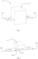
- the illustrated pyrotechnic circuit breaker 2 is designed for use in an on-board power supply of a motor vehicle and is accordingly used in a non-illustrated on-board power supply of a motor vehicle.
- the pyrotechnic circuit breaker 2 comprises a pyrotechnic unit, which is not explicitly shown and is constructed according to a principle known per se, and a separating body 4, the pyrotechnic unit and the separating body 4 being in one 1 indicated housing 6 are housed.
- Part of the pyrotechnic circuit breaker 2 is also a conductor structure 8, which in the exemplary embodiment is formed by a stamped sheet metal and is accordingly formed in one piece and in one piece.
- the conductor structure 8 can be divided into three different functional areas, specifically into two connection arms 10 and a connection arm 12, which mechanically and electrically conductively connects the two connection arms 10 to one another in an initial state.
- connection arms 10 protrude in the exemplary embodiment according to FIG 1 out of the housing 6 and are positioned on opposite sides of the pyrotechnic circuit breaker 2 .
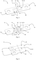
- the two connection arms 10 are positioned on the same side of the pyrotechnic unit 2, the conductor structure 8 then for example according to FIG figure 5 or according to 6 is designed. Regardless of the positioning of the two connection arms 10 in the installed state of the pyrotechnic disconnector 2, one of the two connection arms forms an input connection for a current inflow line and the other of the two connection arms 10 forms an output connection for a current discharge line.
- the connecting arm 12 is severed by the separating body 4 according to a principle known per se, as a result of which the connecting arms 10 are mechanically and electrically separated from one another, which ultimately also leads to a separation of the power supply line and current discharge line leads.
- the pyrotechnic circuit breaker 2 is designed in such a way that a separating piece 14 is separated from the connecting arm 12 if it is triggered. In this way, in the event of tripping or disconnection, several disconnection points are implemented along a potential current path and in this way the risk of formation of an arc is additionally reduced or it is ensured in this way that no arc can form.
- the pyrotechnical isolating switch 2 is also designed in such a way that a retaining lock 16 made of an insulating material, for example a plastic, adheres to the conductor structure 8, which the separating piece 14 after a trigger case holds. That separating piece 14 is expediently held in a fixed position relative to the rest of the conductor structure 8 and accordingly the separating piece 14 is preferably connected to the rest of the conductor structure 8 via the securing device 16 .
- the securing device 16 is further preferably formed by a casting compound which adheres to the conductor structure 8 and is, for example, injection-molded onto the conductor structure 8 or glued to the conductor structure 8 .
- the conductor structure 8 is formed by a stamped sheet metal, which has at least one recess 18 penetrating the stamped sheet metal in the area of the connecting arm 12 .
- Those recesses 18 are at least partially filled with a casting compound made of a plastic and more preferably completely filled to form the securing device 16 .
- the casting compound is only in the recesses 18, so that the respective flexible dies are otherwise free of the corresponding casting compound, that is to say in particular they have no casting compound on the upper side and on the underside. So there are almost only gaps filled with the appropriate casting compound.
- the separating body 4 is indicated in such a way that the connecting arm 12 is severed only along a single separating line 20 .
- a continuous severing along the severing line 20 with a continuous cutting edge in which both the conductor structure 8 and the insulating material of the retaining fuse 16 are severed.
- the conductor structure 8 has a curved course, at least in the area of the connecting arm 12, with the connecting arm 12 being formed by a single, continuous conductor strip 22 which is then, for example, U-shaped, S-shaped or meander-shaped history.
- the separating body cuts through the conductor strip 22 at a plurality of spatially spaced positions, so that in any case at least one separating piece 14 is severed when triggered.
- the dividing line 20 intersects the conductor strip in at least two spatially separated sections along the course of the conductor strip 22 .
- the course of the conductor strip 22 corresponds to a good approximation to the potential current path and accordingly the potential current path is then interrupted at several points in the event of a trip.
- the invention is not limited to the embodiment described above.
Landscapes
- Fuses (AREA)
Claims (9)
- Sectionneur pyrotechnique (2), en particulier pour un réseau de bord d'un véhicule automobile, comportant une structure conductrice (8) munie de deux bras de raccordement (10) et d'un bras de connexion (12) reliant électriquement les deux bras de raccordement (10) et comportant une unité pyrotechnique et un corps de sectionnement (4) destiné au sectionnement du bras de raccordement (12) en cas de déclenchement,
caractérisé en ce
qu'en cas de déclenchement le corps de sectionnement (4) sectionne le bras de raccordement (12) le long d'une ligne de sectionnement (20) unique et en ce que le bras de raccordement (12) est constitué d'une bande conductrice (22) à tracé incurvé, de sorte que la ligne de sectionnement (20) coupe la bande conductrice (22) en au moins deux sections séparées spatialement l'une de l'autre le long du tracé de la bande conductrice (12) et en ce que le corps de sectionnement (4) et/ou le bras de connexion (12) est ou sont conçu(s) de telle façon qu'en cas de déclenchement, une pièce de sectionnement (14) est désolidarisée du bras de connexion (12). - Sectionneur pyrotechnique (2) selon la revendication 1,
caractérisé en ce
qu'une sécurité de maintien (16) en un matériau isolant adhère à la structure conductrice (8) et la pièce de sectionnement (14) est maintenue par la sécurité de maintien (16). - Sectionneur pyrotechnique (2) selon la revendication 2,
caractérisé en ce que
la pièce de sectionnement (14) est maintenue par la sécurité de maintien (16) de manière à rester en sa position initiale après le cas de déclenchement. - Sectionneur pyrotechnique (2) selon la revendication 2 ou 3,
caractérisé en ce
que la sécurité de maintien (16) adhère en tant que masse de remplissage à la structure conductrice (8), est appliquée par injection sur la structure conductrice (8) ou est collée à la structure conductrice (8). - Sectionneur pyrotechnique (2) selon l'une quelconque des revendications 2 à 4,
caractérisé en ce
qu'une tôle découpée constitue la structure conductrice (8), et en ce que la sécurité de maintien (16) est appliquée par injection sur la tôle découpée. - Sectionneur pyrotechnique (2) selon l'une quelconque des revendications 2 à 5,
caractérisé en ce
qu'une tôle découpée constitue la structure conductrice (8), en ce que la tôle découpée comporte au moins un évidement (18) et en ce que ledit au moins un évidement (18) est rempli au moins partiellement avec le matériau isolant, pour la formation de la sécurité de maintien (16). - Sectionneur pyrotechnique (2) selon l'une quelconque des revendications 1 à 6,
caractérisé en ce que
le bras de connexion (12) est constitué d'une bande conductrice (22) qui présente dans un segment une forme en S et en particulier une forme de méandre. - Sectionneur pyrotechnique (2) selon l'une quelconque des revendications 1 à 7,
caractérisé en ce que
les deux bras de connexion (10) sont positionnés du même côté de l'unité pyrotechnique et/ou du corps de sectionnement (4). - Sectionneur pyrotechnique (2) selon l'une quelconque des revendications 1 à 8,
caractérisé en ce
qu'une sécurité de maintien (16) en un matériau isolant adhère à la structure conductrice (8) et en ce que le corps de sectionnement (4) et/ou le bras de raccordement (12) est ou sont constitué(s) de telle façon qu'en cas de déclenchement plusieurs pièces de sectionnement (14) séparées sont désolidarisées du bras de raccordement (12), chaque pièce de sectionnement (14) étant maintenue par la sécurité de maintien (16) en une position relative fixe par rapport à la structure conductrice (8) restante.
Applications Claiming Priority (2)
| Application Number | Priority Date | Filing Date | Title |
|---|---|---|---|
| DE102017207735.2A DE102017207735B3 (de) | 2017-05-08 | 2017-05-08 | Pyrotechnischer Trennschalter |
| PCT/EP2018/060207 WO2018206270A1 (fr) | 2017-05-08 | 2018-04-20 | Sectionneur pyrotechnique |
Publications (2)
| Publication Number | Publication Date |
|---|---|
| EP3622547A1 EP3622547A1 (fr) | 2020-03-18 |
| EP3622547B1 true EP3622547B1 (fr) | 2023-06-07 |
Family
ID=62025878
Family Applications (1)
| Application Number | Title | Priority Date | Filing Date |
|---|---|---|---|
| EP18718830.5A Active EP3622547B1 (fr) | 2017-05-08 | 2018-04-20 | Sectionneur pyrotechnique |
Country Status (3)
| Country | Link |
|---|---|
| EP (1) | EP3622547B1 (fr) |
| DE (1) | DE102017207735B3 (fr) |
| WO (1) | WO2018206270A1 (fr) |
Family Cites Families (10)
| Publication number | Priority date | Publication date | Assignee | Title |
|---|---|---|---|---|
| FR1330778A (fr) | 1962-05-08 | 1963-06-28 | Dispositif régulateur à balancier spiral auto entretenu à fort couple | |
| US3875431A (en) * | 1970-10-16 | 1975-04-01 | Us Navy | Destructible microelectronic circuit element |
| DE102010011150B4 (de) | 2010-03-11 | 2012-03-29 | Auto-Kabel Managementgesellschaft Mbh | Elektrische Sicherung für Kraftfahrzeugenergieleitungen und Herstellungsverfahren für eine solche Sicherung |
| US20140326122A1 (en) * | 2011-11-28 | 2014-11-06 | Daikin Industries, Ltd. | Cutter |
| JP5874583B2 (ja) | 2012-08-29 | 2016-03-02 | 豊田合成株式会社 | 導通遮断装置 |
| DE102012221664B4 (de) | 2012-09-25 | 2022-04-21 | Te Connectivity Germany Gmbh | Kurzschlussabschalter |
| EP2996134B1 (fr) | 2014-09-09 | 2017-04-26 | Airbus Safran Launchers SAS | Coupe-circuit pyrotechnique avec amélioration de la coupe du jeu de barres |
| DE102014222230A1 (de) | 2014-10-30 | 2016-05-04 | Leoni Bordnetz-Systeme Gmbh | Pyrotechnischer Schutzschalter |
| JP6406189B2 (ja) * | 2015-09-11 | 2018-10-17 | 豊田合成株式会社 | 導通遮断装置 |
| AT517872B1 (de) * | 2015-10-19 | 2017-08-15 | Hirtenberger Automotive Safety Gmbh & Co Kg | Pyrotechnische Trennvorrichtung |
-
2017
- 2017-05-08 DE DE102017207735.2A patent/DE102017207735B3/de not_active Expired - Fee Related
-
2018
- 2018-04-20 WO PCT/EP2018/060207 patent/WO2018206270A1/fr not_active Ceased
- 2018-04-20 EP EP18718830.5A patent/EP3622547B1/fr active Active
Also Published As
| Publication number | Publication date |
|---|---|
| EP3622547A1 (fr) | 2020-03-18 |
| DE102017207735B3 (de) | 2018-08-23 |
| WO2018206270A1 (fr) | 2018-11-15 |
Similar Documents
| Publication | Publication Date | Title |
|---|---|---|
| DE112016004764B4 (de) | Pyrotechnische Trennvorrichtung | |
| DE102016107707B3 (de) | Schutzvorrichtung für eine Hochvolt-Spannungsversorgung | |
| EP3622548B1 (fr) | Disjoncteur pyrotechnique et réseau d'alimentation équipé d'un disjoncteur pyrotechnique | |
| EP3102454B1 (fr) | Réseau de bord à haute tension d'un véhicule automobile | |
| EP0690466A1 (fr) | Elément pyrotechnique de protection contre un courant excessif | |
| DE102016213072B4 (de) | Ein Hochvolt-Batteriesystem mit Sicherungseinrichtung | |
| EP3525223B1 (fr) | Commutateur pyrotechnique | |
| DE19712544A1 (de) | Stromkreisunterbrecher und Stromkreisunterbrecherschaltung für ein Kraftfahrzeug | |
| DE102016113773A1 (de) | Schmelzsicherung | |
| EP3622549B1 (fr) | Disjoncteur pyrotechnique et réseau d'alimentation équipé d'un disjoncteur pyrotechnique | |
| WO2019206467A1 (fr) | Commutateur à haute tension, alimentation de bord à haute tension dans un véhicule automobile et procédé de fonctionnement d'un commutateur à haute tension | |
| EP3251141B1 (fr) | Élément de sécurité pyrotechnique | |
| AT524104A1 (de) | Pyrotechnischer Stromtrenner | |
| EP3192093B1 (fr) | Arrangement fusible a multiple borne | |
| EP3622547B1 (fr) | Sectionneur pyrotechnique | |
| DE10111252A1 (de) | Anordnung zum Schutz von Vebrauchern | |
| DE19951095A1 (de) | Vorrichtung zur Sicherung eines elektrischen Netzes | |
| EP3580772B1 (fr) | Fusible conçu pour des applications basse tension | |
| EP3213336B1 (fr) | Disjoncteur de protection pyrotechnique | |
| DE19741828A1 (de) | Elektrischer Sicherheitsschalter für Kraftfahrzeuge | |
| DE102021200782A1 (de) | Schmelzsicherung mit Zündleiter | |
| EP3553806B1 (fr) | Dispositif de génération d'une impulsion de tension | |
| DE102017217520A1 (de) | Sicherheitsanordnung für eine elektrische Komponente eines Kraftfahrzeugs und Kraftfahrzeug mit einer solchen Sicherheitsanordnung | |
| DE102024114312A1 (de) | Pyrotechnischer Stromtrenner | |
| DE102014108245A1 (de) | Sicherheitsvorrichtung zur Unterbrechung einer Hochvoltleitung für ein Kraftfahrzeug |
Legal Events
| Date | Code | Title | Description |
|---|---|---|---|
| STAA | Information on the status of an ep patent application or granted ep patent |
Free format text: STATUS: UNKNOWN |
|
| STAA | Information on the status of an ep patent application or granted ep patent |
Free format text: STATUS: THE INTERNATIONAL PUBLICATION HAS BEEN MADE |
|
| PUAI | Public reference made under article 153(3) epc to a published international application that has entered the european phase |
Free format text: ORIGINAL CODE: 0009012 |
|
| STAA | Information on the status of an ep patent application or granted ep patent |
Free format text: STATUS: REQUEST FOR EXAMINATION WAS MADE |
|
| STAA | Information on the status of an ep patent application or granted ep patent |
Free format text: STATUS: EXAMINATION IS IN PROGRESS |
|
| 17P | Request for examination filed |
Effective date: 20191203 |
|
| AK | Designated contracting states |
Kind code of ref document: A1 Designated state(s): AL AT BE BG CH CY CZ DE DK EE ES FI FR GB GR HR HU IE IS IT LI LT LU LV MC MK MT NL NO PL PT RO RS SE SI SK SM TR |
|
| AX | Request for extension of the european patent |
Extension state: BA ME |
|
| 17Q | First examination report despatched |
Effective date: 20200312 |
|
| DAV | Request for validation of the european patent (deleted) | ||
| DAX | Request for extension of the european patent (deleted) | ||
| GRAP | Despatch of communication of intention to grant a patent |
Free format text: ORIGINAL CODE: EPIDOSNIGR1 |
|
| STAA | Information on the status of an ep patent application or granted ep patent |
Free format text: STATUS: GRANT OF PATENT IS INTENDED |
|
| INTG | Intention to grant announced |
Effective date: 20221202 |
|
| GRAS | Grant fee paid |
Free format text: ORIGINAL CODE: EPIDOSNIGR3 |
|
| GRAA | (expected) grant |
Free format text: ORIGINAL CODE: 0009210 |
|
| STAA | Information on the status of an ep patent application or granted ep patent |
Free format text: STATUS: THE PATENT HAS BEEN GRANTED |
|
| AK | Designated contracting states |
Kind code of ref document: B1 Designated state(s): AL AT BE BG CH CY CZ DE DK EE ES FI FR GB GR HR HU IE IS IT LI LT LU LV MC MK MT NL NO PL PT RO RS SE SI SK SM TR |
|
| REG | Reference to a national code |
Ref country code: GB Ref legal event code: FG4D Free format text: NOT ENGLISH |
|
| REG | Reference to a national code |
Ref country code: CH Ref legal event code: EP Ref country code: AT Ref legal event code: REF Ref document number: 1577504 Country of ref document: AT Kind code of ref document: T Effective date: 20230615 |
|
| REG | Reference to a national code |
Ref country code: DE Ref legal event code: R096 Ref document number: 502018012336 Country of ref document: DE |
|
| P01 | Opt-out of the competence of the unified patent court (upc) registered |
Effective date: 20230527 |
|
| REG | Reference to a national code |
Ref country code: LT Ref legal event code: MG9D |
|
| REG | Reference to a national code |
Ref country code: NL Ref legal event code: MP Effective date: 20230607 |
|
| PG25 | Lapsed in a contracting state [announced via postgrant information from national office to epo] |
Ref country code: SE Free format text: LAPSE BECAUSE OF FAILURE TO SUBMIT A TRANSLATION OF THE DESCRIPTION OR TO PAY THE FEE WITHIN THE PRESCRIBED TIME-LIMIT Effective date: 20230607 Ref country code: NO Free format text: LAPSE BECAUSE OF FAILURE TO SUBMIT A TRANSLATION OF THE DESCRIPTION OR TO PAY THE FEE WITHIN THE PRESCRIBED TIME-LIMIT Effective date: 20230907 Ref country code: ES Free format text: LAPSE BECAUSE OF FAILURE TO SUBMIT A TRANSLATION OF THE DESCRIPTION OR TO PAY THE FEE WITHIN THE PRESCRIBED TIME-LIMIT Effective date: 20230607 |
|
| PG25 | Lapsed in a contracting state [announced via postgrant information from national office to epo] |
Ref country code: RS Free format text: LAPSE BECAUSE OF FAILURE TO SUBMIT A TRANSLATION OF THE DESCRIPTION OR TO PAY THE FEE WITHIN THE PRESCRIBED TIME-LIMIT Effective date: 20230607 Ref country code: NL Free format text: LAPSE BECAUSE OF FAILURE TO SUBMIT A TRANSLATION OF THE DESCRIPTION OR TO PAY THE FEE WITHIN THE PRESCRIBED TIME-LIMIT Effective date: 20230607 Ref country code: LV Free format text: LAPSE BECAUSE OF FAILURE TO SUBMIT A TRANSLATION OF THE DESCRIPTION OR TO PAY THE FEE WITHIN THE PRESCRIBED TIME-LIMIT Effective date: 20230607 Ref country code: LT Free format text: LAPSE BECAUSE OF FAILURE TO SUBMIT A TRANSLATION OF THE DESCRIPTION OR TO PAY THE FEE WITHIN THE PRESCRIBED TIME-LIMIT Effective date: 20230607 Ref country code: HR Free format text: LAPSE BECAUSE OF FAILURE TO SUBMIT A TRANSLATION OF THE DESCRIPTION OR TO PAY THE FEE WITHIN THE PRESCRIBED TIME-LIMIT Effective date: 20230607 Ref country code: GR Free format text: LAPSE BECAUSE OF FAILURE TO SUBMIT A TRANSLATION OF THE DESCRIPTION OR TO PAY THE FEE WITHIN THE PRESCRIBED TIME-LIMIT Effective date: 20230908 |
|
| PG25 | Lapsed in a contracting state [announced via postgrant information from national office to epo] |
Ref country code: FI Free format text: LAPSE BECAUSE OF FAILURE TO SUBMIT A TRANSLATION OF THE DESCRIPTION OR TO PAY THE FEE WITHIN THE PRESCRIBED TIME-LIMIT Effective date: 20230607 |
|
| PG25 | Lapsed in a contracting state [announced via postgrant information from national office to epo] |
Ref country code: SK Free format text: LAPSE BECAUSE OF FAILURE TO SUBMIT A TRANSLATION OF THE DESCRIPTION OR TO PAY THE FEE WITHIN THE PRESCRIBED TIME-LIMIT Effective date: 20230607 |
|
| PG25 | Lapsed in a contracting state [announced via postgrant information from national office to epo] |
Ref country code: IS Free format text: LAPSE BECAUSE OF FAILURE TO SUBMIT A TRANSLATION OF THE DESCRIPTION OR TO PAY THE FEE WITHIN THE PRESCRIBED TIME-LIMIT Effective date: 20231007 |
|
| PG25 | Lapsed in a contracting state [announced via postgrant information from national office to epo] |
Ref country code: SM Free format text: LAPSE BECAUSE OF FAILURE TO SUBMIT A TRANSLATION OF THE DESCRIPTION OR TO PAY THE FEE WITHIN THE PRESCRIBED TIME-LIMIT Effective date: 20230607 Ref country code: SK Free format text: LAPSE BECAUSE OF FAILURE TO SUBMIT A TRANSLATION OF THE DESCRIPTION OR TO PAY THE FEE WITHIN THE PRESCRIBED TIME-LIMIT Effective date: 20230607 Ref country code: RO Free format text: LAPSE BECAUSE OF FAILURE TO SUBMIT A TRANSLATION OF THE DESCRIPTION OR TO PAY THE FEE WITHIN THE PRESCRIBED TIME-LIMIT Effective date: 20230607 Ref country code: PT Free format text: LAPSE BECAUSE OF FAILURE TO SUBMIT A TRANSLATION OF THE DESCRIPTION OR TO PAY THE FEE WITHIN THE PRESCRIBED TIME-LIMIT Effective date: 20231009 Ref country code: IS Free format text: LAPSE BECAUSE OF FAILURE TO SUBMIT A TRANSLATION OF THE DESCRIPTION OR TO PAY THE FEE WITHIN THE PRESCRIBED TIME-LIMIT Effective date: 20231007 Ref country code: EE Free format text: LAPSE BECAUSE OF FAILURE TO SUBMIT A TRANSLATION OF THE DESCRIPTION OR TO PAY THE FEE WITHIN THE PRESCRIBED TIME-LIMIT Effective date: 20230607 Ref country code: CZ Free format text: LAPSE BECAUSE OF FAILURE TO SUBMIT A TRANSLATION OF THE DESCRIPTION OR TO PAY THE FEE WITHIN THE PRESCRIBED TIME-LIMIT Effective date: 20230607 |
|
| PG25 | Lapsed in a contracting state [announced via postgrant information from national office to epo] |
Ref country code: PL Free format text: LAPSE BECAUSE OF FAILURE TO SUBMIT A TRANSLATION OF THE DESCRIPTION OR TO PAY THE FEE WITHIN THE PRESCRIBED TIME-LIMIT Effective date: 20230607 |
|
| REG | Reference to a national code |
Ref country code: DE Ref legal event code: R097 Ref document number: 502018012336 Country of ref document: DE |
|
| PLBE | No opposition filed within time limit |
Free format text: ORIGINAL CODE: 0009261 |
|
| STAA | Information on the status of an ep patent application or granted ep patent |
Free format text: STATUS: NO OPPOSITION FILED WITHIN TIME LIMIT |
|
| PG25 | Lapsed in a contracting state [announced via postgrant information from national office to epo] |
Ref country code: DK Free format text: LAPSE BECAUSE OF FAILURE TO SUBMIT A TRANSLATION OF THE DESCRIPTION OR TO PAY THE FEE WITHIN THE PRESCRIBED TIME-LIMIT Effective date: 20230607 |
|
| PG25 | Lapsed in a contracting state [announced via postgrant information from national office to epo] |
Ref country code: SI Free format text: LAPSE BECAUSE OF FAILURE TO SUBMIT A TRANSLATION OF THE DESCRIPTION OR TO PAY THE FEE WITHIN THE PRESCRIBED TIME-LIMIT Effective date: 20230607 |
|
| 26N | No opposition filed |
Effective date: 20240308 |
|
| PG25 | Lapsed in a contracting state [announced via postgrant information from national office to epo] |
Ref country code: SI Free format text: LAPSE BECAUSE OF FAILURE TO SUBMIT A TRANSLATION OF THE DESCRIPTION OR TO PAY THE FEE WITHIN THE PRESCRIBED TIME-LIMIT Effective date: 20230607 Ref country code: IT Free format text: LAPSE BECAUSE OF FAILURE TO SUBMIT A TRANSLATION OF THE DESCRIPTION OR TO PAY THE FEE WITHIN THE PRESCRIBED TIME-LIMIT Effective date: 20230607 |
|
| REG | Reference to a national code |
Ref country code: DE Ref legal event code: R119 Ref document number: 502018012336 Country of ref document: DE |
|
| PG25 | Lapsed in a contracting state [announced via postgrant information from national office to epo] |
Ref country code: BG Free format text: LAPSE BECAUSE OF FAILURE TO SUBMIT A TRANSLATION OF THE DESCRIPTION OR TO PAY THE FEE WITHIN THE PRESCRIBED TIME-LIMIT Effective date: 20230607 |
|
| PG25 | Lapsed in a contracting state [announced via postgrant information from national office to epo] |
Ref country code: MC Free format text: LAPSE BECAUSE OF FAILURE TO SUBMIT A TRANSLATION OF THE DESCRIPTION OR TO PAY THE FEE WITHIN THE PRESCRIBED TIME-LIMIT Effective date: 20230607 |
|
| PG25 | Lapsed in a contracting state [announced via postgrant information from national office to epo] |
Ref country code: MC Free format text: LAPSE BECAUSE OF FAILURE TO SUBMIT A TRANSLATION OF THE DESCRIPTION OR TO PAY THE FEE WITHIN THE PRESCRIBED TIME-LIMIT Effective date: 20230607 Ref country code: BG Free format text: LAPSE BECAUSE OF FAILURE TO SUBMIT A TRANSLATION OF THE DESCRIPTION OR TO PAY THE FEE WITHIN THE PRESCRIBED TIME-LIMIT Effective date: 20230607 |
|
| REG | Reference to a national code |
Ref country code: CH Ref legal event code: PL |
|
| PG25 | Lapsed in a contracting state [announced via postgrant information from national office to epo] |
Ref country code: LU Free format text: LAPSE BECAUSE OF NON-PAYMENT OF DUE FEES Effective date: 20240420 |
|
| GBPC | Gb: european patent ceased through non-payment of renewal fee |
Effective date: 20240420 |
|
| REG | Reference to a national code |
Ref country code: BE Ref legal event code: MM Effective date: 20240430 |
|
| PG25 | Lapsed in a contracting state [announced via postgrant information from national office to epo] |
Ref country code: LU Free format text: LAPSE BECAUSE OF NON-PAYMENT OF DUE FEES Effective date: 20240420 |
|
| PG25 | Lapsed in a contracting state [announced via postgrant information from national office to epo] |
Ref country code: DE Free format text: LAPSE BECAUSE OF NON-PAYMENT OF DUE FEES Effective date: 20241105 |
|
| PG25 | Lapsed in a contracting state [announced via postgrant information from national office to epo] |
Ref country code: BE Free format text: LAPSE BECAUSE OF NON-PAYMENT OF DUE FEES Effective date: 20240430 |
|
| PG25 | Lapsed in a contracting state [announced via postgrant information from national office to epo] |
Ref country code: GB Free format text: LAPSE BECAUSE OF NON-PAYMENT OF DUE FEES Effective date: 20240420 |
|
| PG25 | Lapsed in a contracting state [announced via postgrant information from national office to epo] |
Ref country code: FR Free format text: LAPSE BECAUSE OF NON-PAYMENT OF DUE FEES Effective date: 20240430 |
|
| PG25 | Lapsed in a contracting state [announced via postgrant information from national office to epo] |
Ref country code: GB Free format text: LAPSE BECAUSE OF NON-PAYMENT OF DUE FEES Effective date: 20240420 Ref country code: FR Free format text: LAPSE BECAUSE OF NON-PAYMENT OF DUE FEES Effective date: 20240430 Ref country code: DE Free format text: LAPSE BECAUSE OF NON-PAYMENT OF DUE FEES Effective date: 20241105 Ref country code: BE Free format text: LAPSE BECAUSE OF NON-PAYMENT OF DUE FEES Effective date: 20240430 Ref country code: CH Free format text: LAPSE BECAUSE OF NON-PAYMENT OF DUE FEES Effective date: 20240430 |
|
| PG25 | Lapsed in a contracting state [announced via postgrant information from national office to epo] |
Ref country code: IE Free format text: LAPSE BECAUSE OF NON-PAYMENT OF DUE FEES Effective date: 20240420 |
|
| REG | Reference to a national code |
Ref country code: AT Ref legal event code: MM01 Ref document number: 1577504 Country of ref document: AT Kind code of ref document: T Effective date: 20240420 |
|
| PG25 | Lapsed in a contracting state [announced via postgrant information from national office to epo] |
Ref country code: AT Free format text: LAPSE BECAUSE OF NON-PAYMENT OF DUE FEES Effective date: 20240420 |
|
| PG25 | Lapsed in a contracting state [announced via postgrant information from national office to epo] |
Ref country code: CY Free format text: LAPSE BECAUSE OF FAILURE TO SUBMIT A TRANSLATION OF THE DESCRIPTION OR TO PAY THE FEE WITHIN THE PRESCRIBED TIME-LIMIT; INVALID AB INITIO Effective date: 20180420 |
|
| PG25 | Lapsed in a contracting state [announced via postgrant information from national office to epo] |
Ref country code: HU Free format text: LAPSE BECAUSE OF FAILURE TO SUBMIT A TRANSLATION OF THE DESCRIPTION OR TO PAY THE FEE WITHIN THE PRESCRIBED TIME-LIMIT; INVALID AB INITIO Effective date: 20180420 |